

Page 1
100 Ton Ram
Page 2

Table of Contents
Holedall Concept
1
Specifications
2
1¼" through 4" Standard and Long Holedall Swaged Couplings
3
1¼" through 4" Standard and Long Flanged Holedall Swaged Couplings
using Collar with Jack Screws
4
RSTxxxNOS Stems with GASxxxxNOS Ferrules
5
Cam and Groove Holedall Couplings
6
Boss Ground Joint Holedall Couplings
7
Converting from Swaging to Internal Expansion
8
Internal Expansion of Steel and Stainless Steel couplings
9
10
Internal Expansion of H520 couplings
Parts List, Attachments & Sample Forms
Page 3

100 Ton Ram Instruction Manual
The Concept of the Holedall Coupling
Applied with the Ram
The application of Holedall couplings to hose is best described as a
swaging of the coupling to the hose is accomplished by pushing the tubular ferrule (normally made of tubular
steel, but also available in brass or stainless steel) through a split die which reduces the ferrule O.D. causing the
ferrule to penetrate into the hose wall. This results in a 360° uninterrupted compression band around the hose.
The patented Holedall coupling includes a hose stem and a ferrule. The hose stem is of a conventional
serrated design, including a collar which locks the ferrule to the stem. The tubular ferrule will include a top
(outboard) row of holes and, depending on style of ferrule, a bottom (inboard) row of holes and a series of
serrations (if present, depending upon style) inside. The purpose or design function of the holes and serrations
(if present, depending upon style) is as follows:
1. Upon insertion of the stem into the hose, prior to the swage, the top (outboard) row of holes affords positive
proof, attained by visual inspection, that the stem portion of the coupling is fully inserted into the hose.
2. The ferrule holes and serrations provide additional holding power to the coupling.
This is effected as follows:
The Holedall coupling is applied directly to the raw end of the hose without, in any manner, altering the
hose cover.
hose wall under the strong compression band of the swaged ferrule tends to be displaced (rubber is not
compressible), it is therefore necessary to provide an escape area for this displacement. The ferrule
holes provide a portion of this and thus permit a tighter compression band. At the same time, we use this
rubber displacement to enhance the holding power of the coupling. The serrations (if present depending
upon style) are located under the compression band (swaged area) of the ferrule and act as “teeth”
biting into the hose cover.
The hose cover need not be skived or buffed off. However, since the rubber content of the
draw type progressive swage
. This
3. Upon completion of the swage, the holes serve still another function. By visual inspection of the coupling,
the holes provide an indication of the adequacy of the swage. Rubber will normally project through the
bottom (inboard) row of holes (when present) and at least flow into the holes in the top (outboard) reservoir
area. The reservoir area should fill up (except when hose wall thickness is below 5/16").
The contour or swaged form of the Holedall coupling provides additional holding power (coupling retention).
The design of the ram swaging dies effect a swaged form to the Holedall coupling in which it should
be noted that the ferrule is not swaged its entire length. With the draw type progressive swage, the Holedall
coupling utilizes a planned forward (outboard) cold flow of the rubber content of the hose wall into the reservoir
area of the coupling. The hose wall, which is confined between the coupling stem and the tubular ferrule, should
(with our type swage) only move forward (outboard). As this occurs, the hose wall tends to slightly thin out in the
area of the swage and to become heavier in the forward reservoir area. Thus, when a Holedall coupling is
swaged onto a hose much of the same result is accomplished that is effected when one slides a nut onto a
section of rigid tubing and then flares the tubing. The nut cannot slide past the flared end of tubing and likewise
the Holedall coupling cannot slide past the flared hose end.
The die reduction, which effects the penetration of the ferrule into the hose wall, may vary with hose wall
construction. A Holedall coupling may be applied to almost any type of hose construction style with excellent
results. The degree of die reduction or subsequent ferrule penetration into the hose wall is dependent upon a
number of variable conditions, including the compound nature and thickness of the tube, the compound nature
and thickness of the cover stock, and the material and construction design of the reinforcing members. Desirable
ferrule penetration into the hose wall is normally approximately 20% of the hose wall thickness, but
the construction of the hose wall. In order to effect the proper ferrule penetration into the hose wall and to provide
compression band to withstand the hoop stress, it is necessary to increase the gauge or thickness of the ferrule
wall. Generally as the hose wall thickens and hose size increases, the ferrule is made with an increased wall
thickness.
it will vary
with
Holedall Concept 1
Page 4

100 Ton Ram Instruction Manual
Listed below are a few guidelines for correct swaging procedures:
1. Always measure (with a diameter tape) the hose free O.D. Both ends of the hose must be measured.
Free O.D. is outside diameter before stem is inserted.
2. For hoses having a wall thickness of 5/16" or greater, chamfer hose tube at 45° angle by 1/8" wide.
This is done prior to stem insertion and will help eliminate the hose end from flaring when the stem is
fully inserted.
3. Select the correct ferrule from the die and ferrule chart by using the combination of hose I.D. and free O.D.
Ferrule must be able to slip over stem and hose without removing (skiving or buffing) hose cover.
4. Select a die (from die and ferrule chart) based upon the free O.D. measured for the end to be swaged to
effect a 18% to 24% reduction.
5. For standard length stems and ferrules, swage is complete when the pusher face meets the die face.
For long length stems and ferrules, effect as long a swage as possible. (See footnote on next page)
6. Apply a high viscosity lubricant (grease or oil) to ferrule O.D.
and die I.D. before initiating swage.
Crisco works best for most swaging procedures.
7. Inspect (visually) the completed swage of coupling, both external and internal where possible.
Troubleshooting: Listed below are some troubles that may occur and their causes:
Trouble
1. Ferrule cracks
Causes
1. Too small a ferrule size
2. Too small a die selection
2. Hose cover bulge behind ferrule
1. Too small a ferrule size
2. Too small a die selection
3. Hose tube bulge (internal bulge)
1. Too small a ferrule size
2. Too small a die selection
4. Ferrule bulges or collapses at top portion
1. Too small a ferrule size
2. Too small a die selection
3. Length of swage too long
4. Ferrule and stem not in proper
position when swage was initiated
5. Buckling or collapsing of coupling stem
1. Too small a ferrule size
2. Too small a die selection
Trouble may occur which is related to the hose design and manufacture. For good coupling application and
performance, it is essential that hose manufacturers be concerned with the requirements for good coupling
retention. Tensile strength, elasticity, durometer hardness, cold flow characteristics and adhesion of hose
components all effect coupling performance.
Holedall Concept2
Page 5

100 Ton Ram Instruction Manual
Footnote
The normal swage length, for standard length stems and ferrules, is obtained by terminating the swage when
the top (outboard) holes completely pass into the lead portion of the die. In other words, when the face of the
pusher meets or touches the face of the die, the swage is complete. When using long length stems and ferrules,
it may be necessary to terminate the swage sooner. If rubber start s to extrude out of the top (outboard) holes or
the top (reservoir area) of the ferrule begins to swell before the normal swage length is effected, stop the swage.
The Ram pressure gauge provides another guide for correct swaging procedures.
pressure gauges. These gauges provide a line pressure reading in PSI (Pounds per Square Inch). For example:
the 100 Ton Ram includes an electric motor driven hydraulic pump capable of developing 10,000 PSI. The area of
the piston head of the ram cylinder is 20.6 square inches. Thus, our maximum ram force is 10,000 x 20.6 or
206,000 pounds, which is equivalent to approximately 100 tons.
All hoses of one size and style should require approximately the same ram force for swaging. However, since
the Ram is intended for use with a variety of hoses of varying constructions and hose wall thickness, we therefore
cannot provide a chart of recommended pressure gauge readings. Dixon strongly recommends the recording of
data such as hose type, I.D. size, O.D. measurement for each end, ferrule used each end, die used each end
and pressure (PSI) required to effect the swage on each end. The Ram user, with this database and his/her
experience, will consistently produce quality hose assemblies.
All Rams are equipped with
General Guidelines
1. This manual supersedes all previous instructions for the 100 Ton Ram.
2. Operator(s) should wear safety apparel such as safety glasses and steel toe shoes when
operating this equipment.
3. The Holedall Coupling System and the procedures in this manual are an engineered system.
Skipping or eliminating steps in the procedure, unless directed to do so, can lead to an assembly failure.
4. Do not “mix and match” stems, ferrules and accessories from manufacturers other than
Dixon Valve & Coupling Comp any.
5. After assembly is complete, pressure test the assembly in accordance with Rubber Manufacturers
Association (RMA) specifications.
6. For questions or assistance, please call Dixon V alve & Coupling Comp any at 1-800-355-1991.
The information contained in this manual applies to couplings engineered and produced by Dixon Valve
and Coupling Company for permanent attachment to hoses. It is to be used only as a guide and does
not address special, unusual, unique or non-standard coupling applications. If you have any questions
regarding any application, please call Dixon at 1-877-963-4966.
Holedall Concept 3
Page 6

Page 7

Section 1
100 Ton Ram
Specifications
Dixon Valve & Coupling Company
800 High Street • Chestertown, MD 21620
ph: 800•355•1991 fax: 800•283•4966
www.dixonvalve.com
Page 8

Page 9
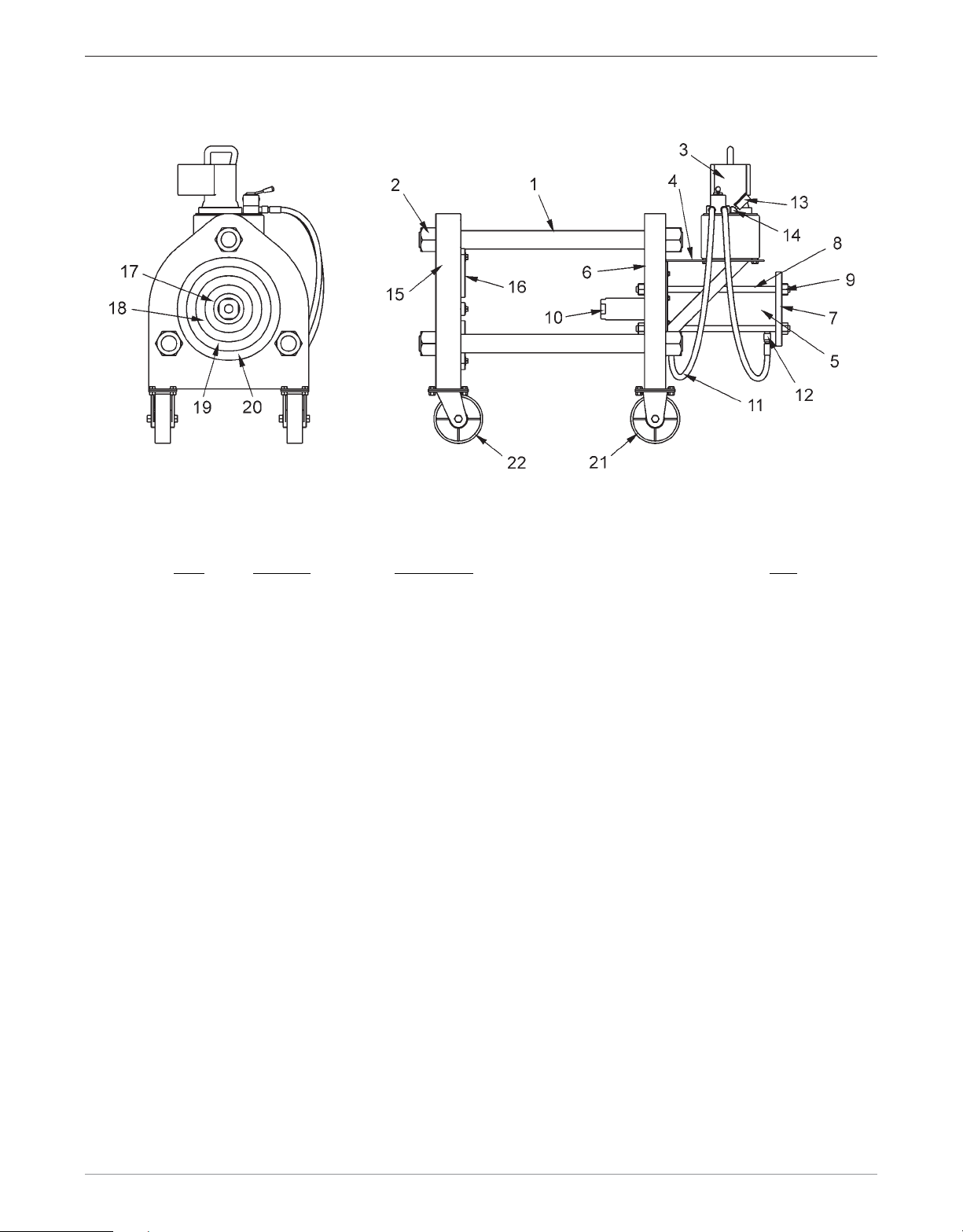
100 Ton Ram Instruction Manual
Item
1
2
3
4
5
6
7
8
9
10
11
12
13
14
15
16
17
18
19
20
21
22
Part No.
001-0003
001-0004
001-0008
001-0011
001-0052
001-0053
001-0017
001-0016
001-0005
0010-064
001-0019
31-300
GLSS10000
001-0024
001-0001
0010-154
M012-001
M012-002
M012-003
M012-004
001-0009
001-0010
Description
Tie Rod
Tie Rod Hex Nut
Hydraulic Pump
Hydraulic Pump Support
Hydraulic Cylinder
Cylinder End Plate
Cylinder Backing Plate
Cylinder Tie Rod
Cylinder Tie Rod Nut
Rod Cap
Hydraulic Hose with Hydraulic Couplings
Hydraulic Quick Connect NPT Plug
0-10,00 P.S.I. Liquid Filled Gauge
Gauge Adapter
Die Bed Plate
Die Retainer Strap
9" Die Carrier
12" Die Carrier
15" Die Carrier
18" Die Carrier
rigid
Steel Wheel (
Steel Wheel (
)
swivel
)
Qty.
3
6
1
1
1
1
1
4
8
1
2
2
1
1
1
6
1
1
1
1
2
2
Section 1
Specifications
1
Page 10

100 Ton Ram Instruction Manual
Specifications:
Net Weight 1,900 lbs., basic equipment only
Crated Weight 2,100 lbs.
Dimensions 60" long x 26" wide x 48" high
Crated Dimension 76" long x 40" wide x 48" high
Pump Motor Power Team PE554 1-1/8 H.P. Universal Motor;
12,000 RPM; 115V single phase, 60/50 cycle AC (not dual voltage);
25 Amp, lightweight “handle-top” housing
Motor Control “Run-Off-Remote” motor control switch; 25 Amp motor control relay
Cavity mounted in motor housing, hand held remote switch
Safety Valves Relief valve set at 10,000 PSI
Control Valve Built-in manually operated 4-way control valves with 3/8" NPT port
Gauge Calibrated 0-10,000 PSI
Reservoir Convenient mounting holes in base
Oil Delivery 650 cu. in/min. at 100 PSI
80 cu. in/min. at 1,000 PSI
70 cu. in/min. at 5,000 PSI
55 cu. in/min. at 10,000 PSI
Note
: 2-stage pump provides fast, no load approach speed and then shifts into slow actuation
as the load is applied.
• Ram double acting (Power Team RD10013)
• 13-1/8" stroke
• 103.1 tons of push at 10,000 PSI
• 44.2 tons of pull at 10,000 PSI
Preparations:
Filling the Reservoir Before removing the filler plug, clean the area around the plug.
The pump is a precision built unit, so special care should be taken to preclude
foreign particles from entering the reservoir. With cylinder fully retracted, fill the
tank 1" to 1½" from the top. Replace the filler plug.
Approved Hydraulic Power Team 9637 Mobile DTE25 or equivalent.
Oils
Available Motor 220-440, etc. Also 1½ H.P. and 3 H.P.
Variations
Reservoir 5 gallon or 10 gallon reservoir available
Variations
The standard 1-1/8 H.P., 12,000 RPM, 115 volt motor and the 2½ gallon reservoir has proven highly successful.
Dixon feels it is the best design, and variations are not desirable.
2
Specifications
Section 1
Page 11
100 Ton Ram Instruction Manual
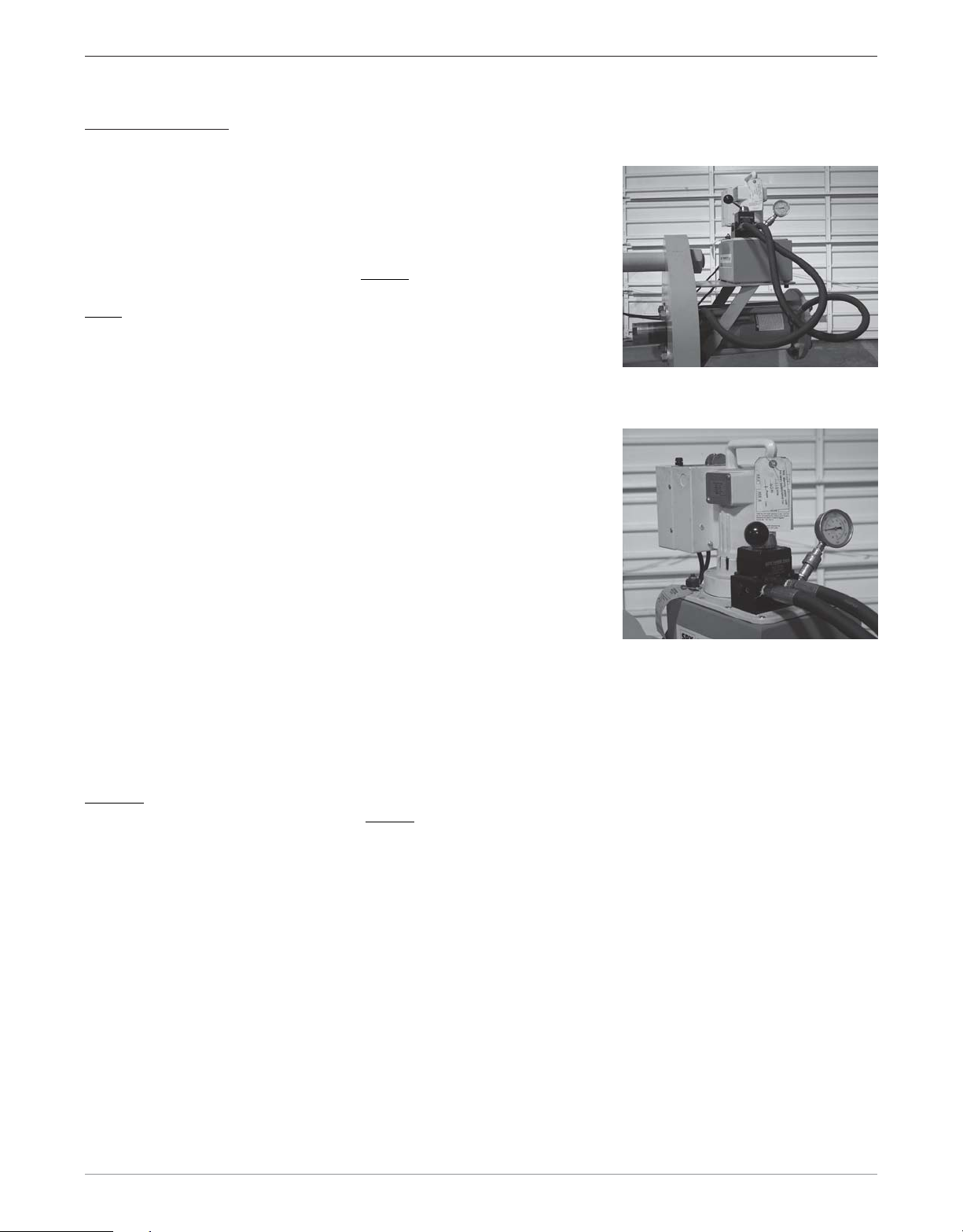
Operating Controls
• F-N-R (Forward-Neutral-Reverse) directional control lever.
The F-N-R lever (shown in the neutral position) controls the
direction of the ram cylinder. To extend the cylinder (forward) in the
direction of the die bed, move the lever
toward the pump motor then
activate the pump. To retract the cylinder (reverse), move the lever
away from the pump motor then activate the pump.
• On-Off-Remote switch, 0 - 10,000 psi pressure gage and hand held
remote.
When the toggle switch is placed in the “On” position, the pump
motor will run until the toggle switch is placed in the “Off” position.
When the toggle switch is placed in the “Remote” position, the hand
held remote is activated. To run the pump motor, depress and hold
the switch on the remote. To stop the motor, release the switch on
the remote. For practical purposes, leave the toggle switch in the
“Remote” position. All future references to activating the pump motor
should be understood that the hand held remote is being used.
Caution!
Never dead-end the cylinder (fully extended or fully retracted) and leave it with pressure showing on
the gage. If the cylinder is dead-ended, always move the lever to the neutral position after stopping the pump.
Failure to do so can shorten the life of the cylinder seals.
Section 1
Specifications
3
Page 12

Page 13
Section 2
100 Ton Ram Operating Instructions
for
1-1/4" through 4" Standard & Long
Holedall Swaged Couplings
Dixon Valve & Coupling Company
800 High Street • Chestertown, MD 21620
ph: 800•355•1991 fax: 800•283•4966
www.dixonvalve.com
Page 14

Page 15
100 Ton Ram Instruction Manual
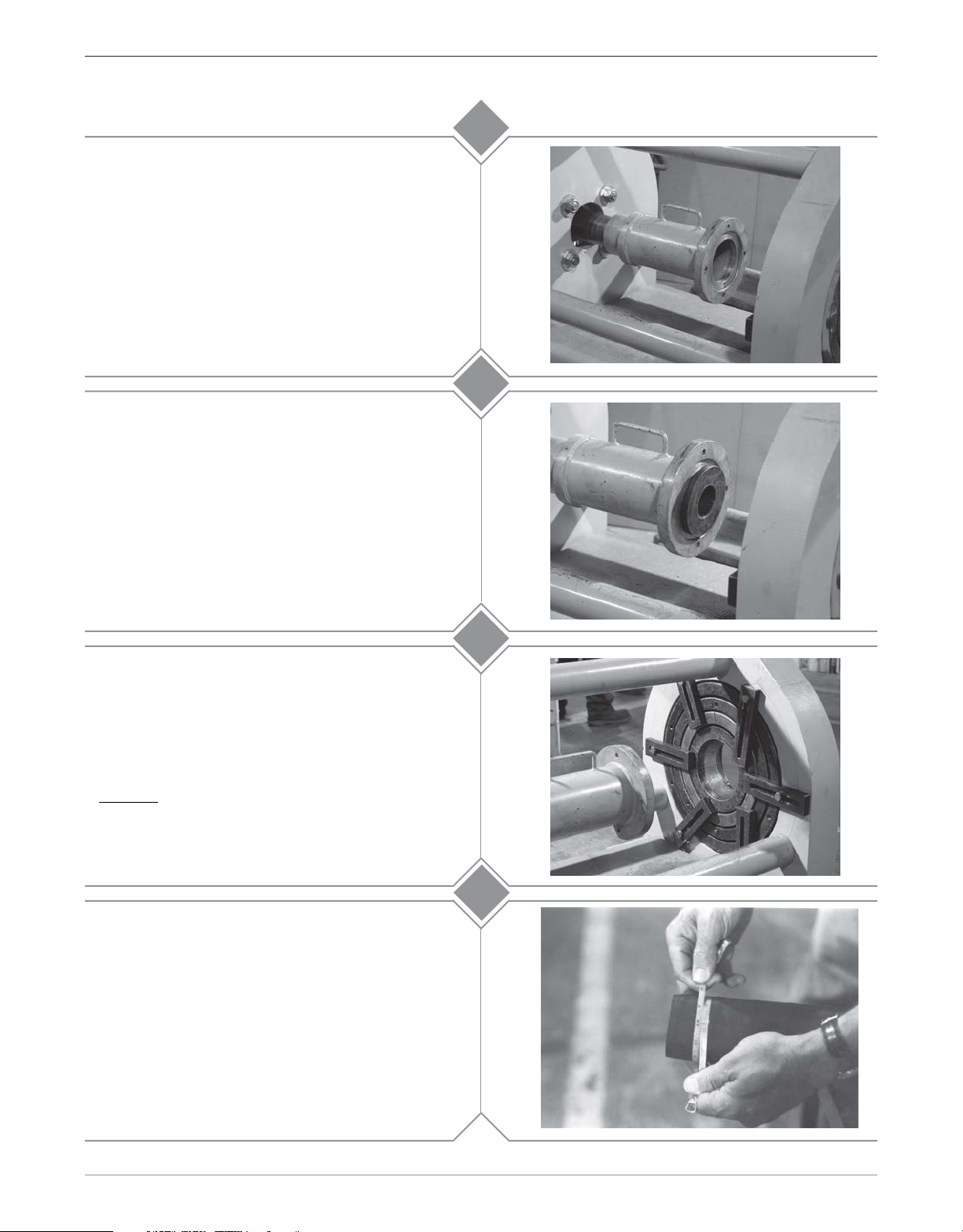
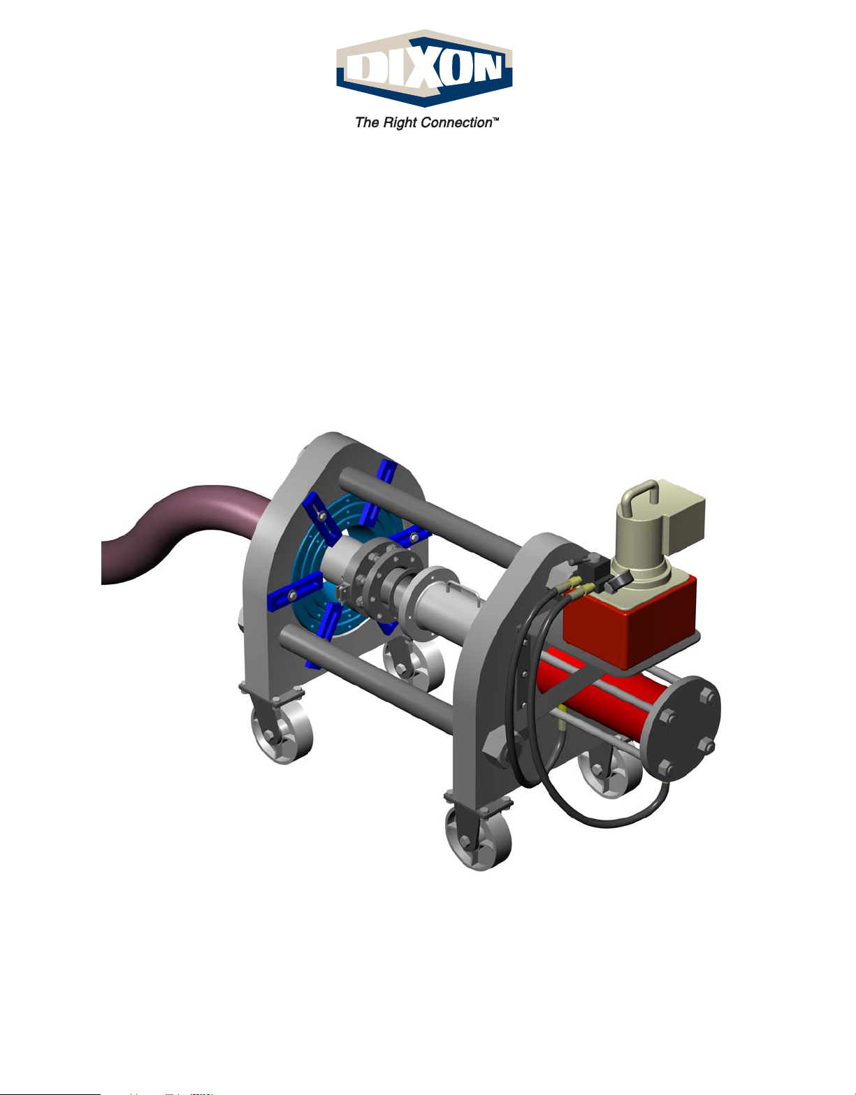
Install the 4" main pusher (M011-065) by sliding it
onto the rod cap of the ram cylinder. Make sure that
the pusher is all the way on the rod cap.
1a
For 1-1/4" - 3" couplings proceed to
For 4" couplings, proceed to
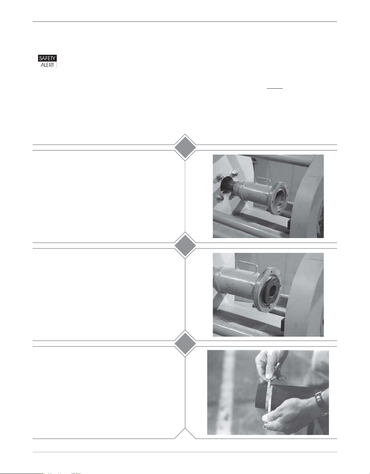
For 1-1/4" - 3" couplings insert the appropriate size
adapter pusher into the 4" main pusher (M011-065).
Shown here is the 2" adapter pusher (M011-115)
being inserted.
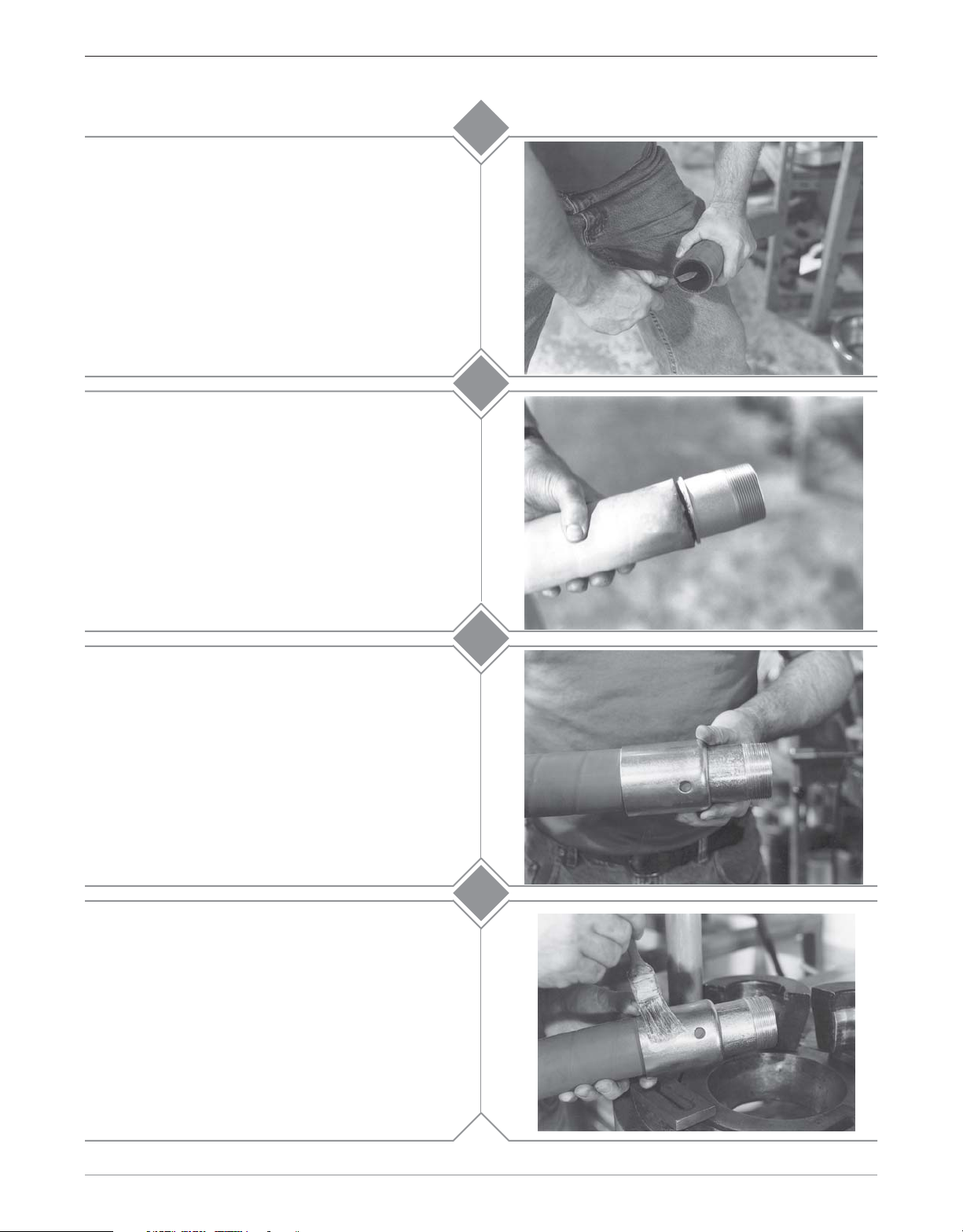
Install the required die holders ensuring that the
seams between the die holder halves do not line up.
The die holders are designed to fit one inside the
other.
A guideline for selecting die holders is:
M012-001 1-1/4" - 3" I.D. hose
M012-002 4" - 6" I.D. hose
Caution!
Never use a swaging die as a die holder!
Step 2
Step 1b
.
.
1b
2
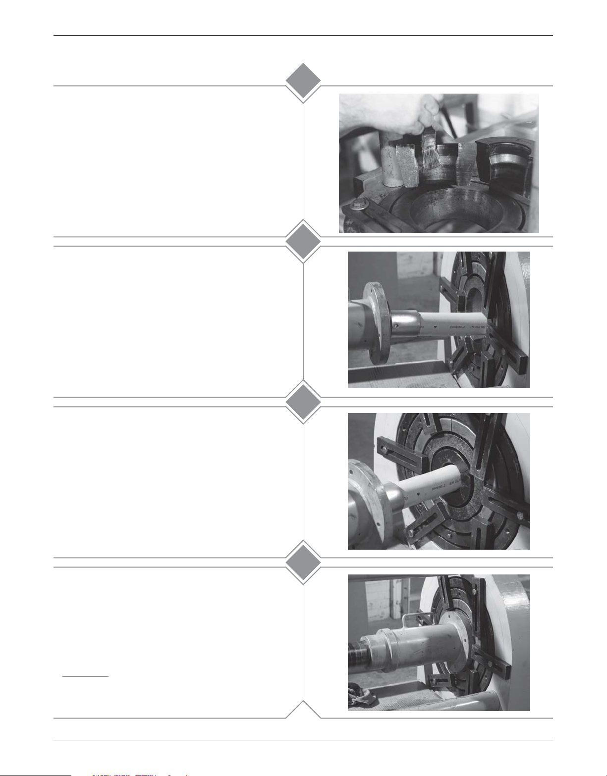
Secure the die holders with tie down bars to prevent
the die holders from slipping out of the die bed
unexpectedly.
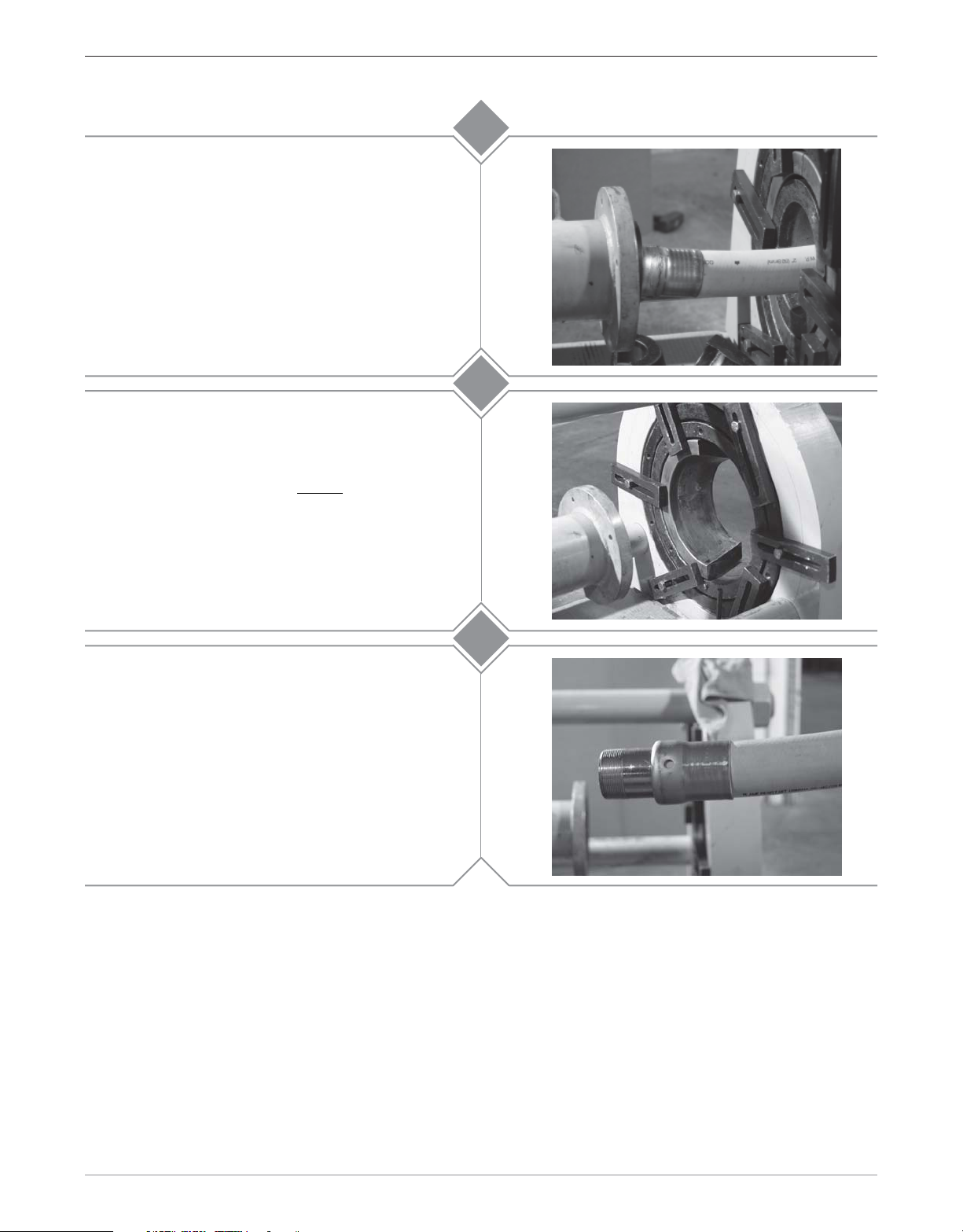
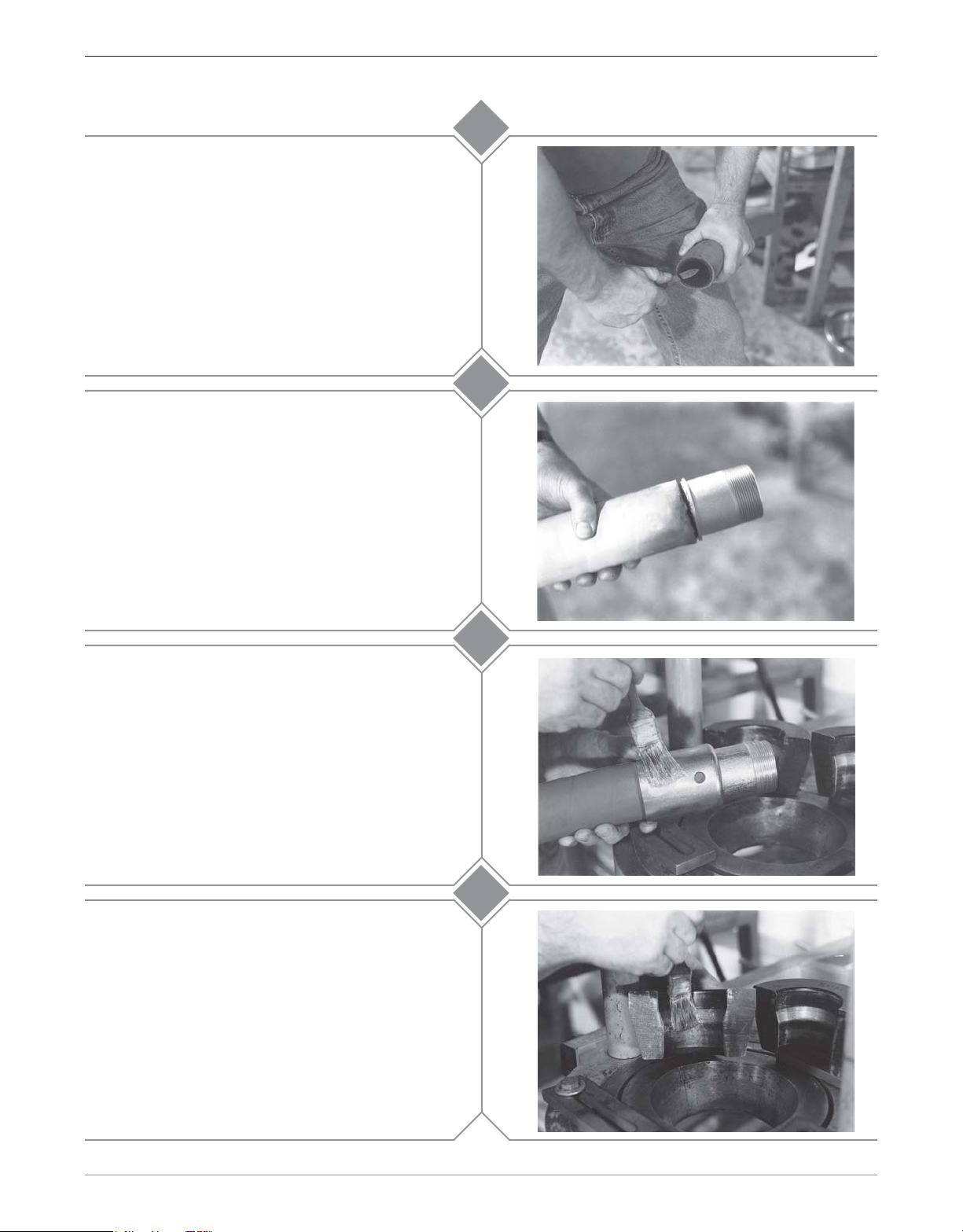
Accurately measure the hose O.D. with a diameter
tape. Each end of the hose should be measured to
guarantee the correct ferrule and die selection.
Select the correct ferrule and die based upon the
hose free O.D. just measured from the die chart.
1-1/4" through 4" Standard & Long Holedall Swaged Couplings
customer service 800•355•1991
3
1Section 2
Page 16
100 Ton Ram Instruction Manual
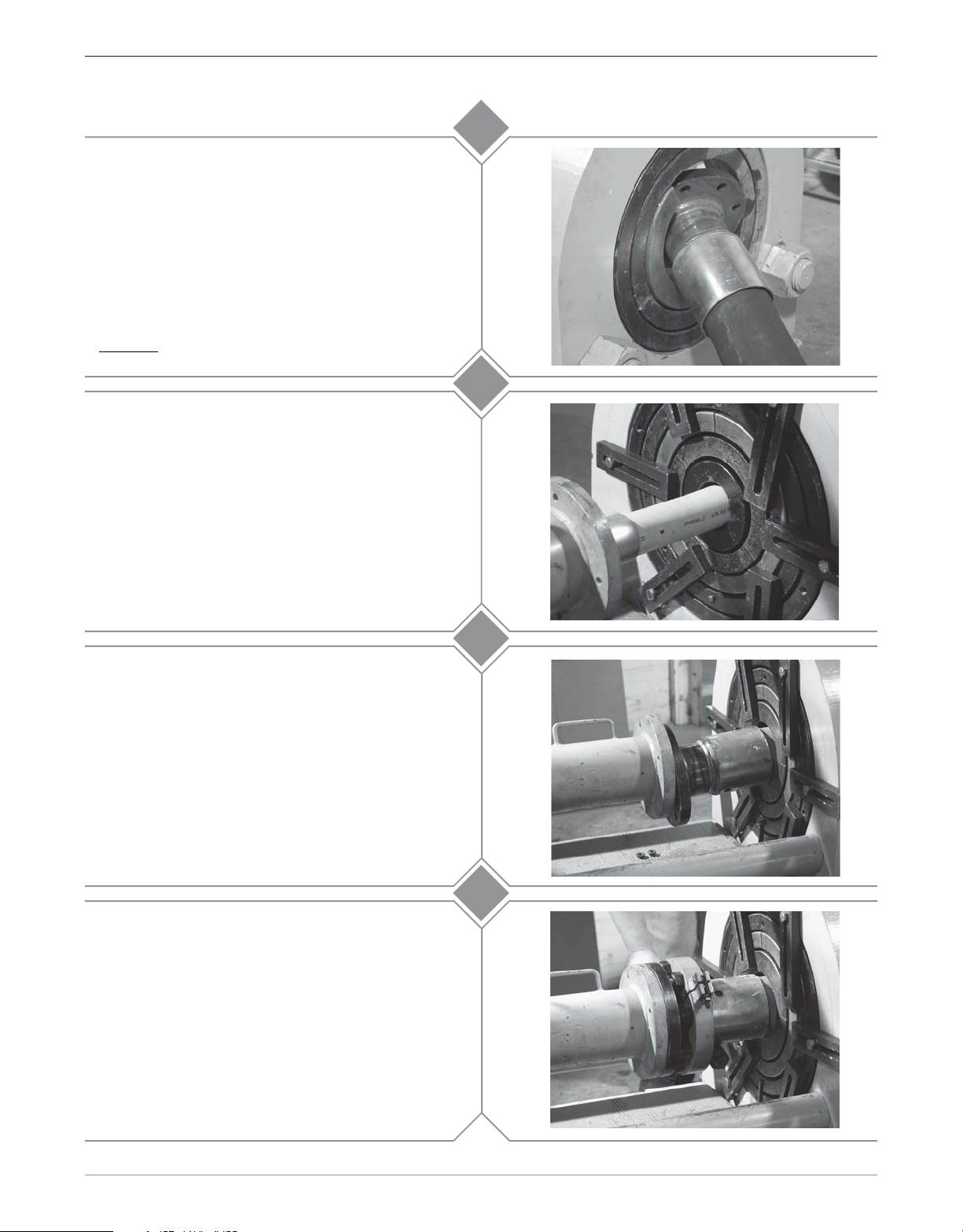
Assuring that the hose end is cut square, chamfer
the I.D. of the hose 1/8" at a 45° angle. This will aid
in stem insertion. If the hose is to be static
grounded, follow hose manufacturers procedure for
proper static grounding.
Lubricate the I.D. of the hose and the O.D. of the
stem with Dixon Coupling Lubricant or equivalent.
Insert the stem all the way into the hose until the ring
on the stem comes in contact with the end of the
hose.
4
5
Slide the ferrule over the stem and over the O.D. of
the hose until the turned over portion of the ferrule
rests on the ring of the stem.
Lubricate the outside of the ferrule with Crisco®
(recommended) or high viscosity oil or heavy duty
grease.
6
7a
2 Section 2
1-1/4" through 4" Standard & Long Holedall Swaged Couplings
customer service 800•355•1991
Page 17
100 Ton Ram Instruction Manual
Lubricate the I.D. of both die halves with Crisco®
(recommended) or high viscosity oil or heavy duty
grease.
Bring the hose with the stem and ferrule through the
die bed. Insert the stem into the pusher so that the
ferrule contacts the pusher. Make sure that there is
sufficient room between the die holders and the end
of the ferrule to comfortably insert the die halves into
the die holders.
7b
8
Lifting up the hose, insert one die half under the
hose. Lower the hose so that it rests on the die.
Insert the other die half. Make sure that the seams
of the die do not line up with the seams on the die
holders.
Continue to jog the cylinder until pressure begins to
register on the gauge. Leave the directional control
lever in the “FORWARD” position. Loosen the bolt
on the tie down bar that is holding the die in place.
Move the tie down bar so that the entire flange on
the pusher will clear. Move any other tie down bars
that may interfere with the pusher. When the pusher
contacts the die release the pressure.
Important!
ferrule with the pusher. Make sure the collar (ring)
on the stem is in contact with the ferrule before
proceeding.
Inspect the position of the stem and
9
10
1-1/4" through 4" Standard & Long Holedall Swaged Couplings
customer service 800•355•1991
3Section 2
Page 18
100 Ton Ram Instruction Manual
Move the directional control lever to the “REVERSE”
position and depress the button on the remote.
Retract the cylinder far enough (approximately 1") to
allow a tie down bar be placed so that the die does
not come out of the die holder. Secure the tie down
bar by tightening the bolt. Continue retracting the
cylinder until there is sufficient room for the stem
and ferrule to clear the die bed.
Position a rubber sheet or pad under the die bed.
While holding the die in place with one hand, loosen
the bolt on the tie down bar and move the tie down
bar so that it clears the die.
towards the pusher. When the die clears the die
holder, one or both halves may fall to the floor. If
one half remains on the ferrule, tap it with a mallet
until it releases. If both halves remain on the ferrule,
it may require the halves be pried apart at the seam.
Slowly
slide the hose
11
12a
Wipe excess lubricant from hose and ferrule. Bring
hose with stem and ferrule back through die bed.
12b
4 Section 2
1-1/4" through 4" Standard & Long Holedall Swaged Couplings
customer service 800•355•1991
Page 19
Section 3
100 Ton Ram Operating Instructions
for
1-1/4" through 4" Standard & Long
Flanged Holedall Swaged Couplings
using Collar with Jack Screws
Dixon Valve & Coupling Company
800 High Street • Chestertown, MD 21620
ph: 800•355•1991 fax: 800•283•4966
www.dixonvalve.com
Page 20

Page 21
100 Ton Ram Instruction Manual
Any coupling assembly (welding of stem, stub end, flange, etc.) must be done prior to
starting this procedure. Failure to do so (i.e. welding flange to stem
after the swage)
can result in serious structural damage to the hose and premature assembly failure.
1a
Install the 4" main pusher (M011-065) by sliding it
onto the rod cap of the ram cylinder. Make sure that
the pusher is all the way on the rod cap.
For 1-1/4" - 3" couplings proceed to
For 4" couplings, proceed to
For 1-1/4" - 3" couplings insert the appropriate size
adapter pusher into the 4" main pusher (M011-065).
For example:
Shown here is the 2" adapter pusher (M011-113)
being inserted.
Accurately measure the hose O.D. with a diameter
tape. Each end of the hose should be measured to
guarantee the correct ferrule and die selection.
Select the correct ferrule and die based upon the
hose free O.D. just measured from the die chart.
Step 2
Step 1b
.
.
1b
2
Section 3
1-1/4" through 4" Standard & Long Flanged Holedall Swaged Couplings using Collar with Jack Screws
customer service
800•355•1991
1
Page 22
100 Ton Ram Instruction Manual
Assuring that the hose end is cut square, chamfer
the I.D. of the hose 1/8" at a 45° angle. This will aid
in stem insertion. If the hose is to be static
grounded, follow hose manufacturers procedure for
proper static grounding.
Lubricate the I.D. of the hose and the O.D. of the
stem with Dixon Coupling Lubricant or equivalent.
Insert the stem into the hose until the hose end
contacts the stem collar. Position the sight hole on
the ferrule so that this can be observed. After stem
insertion, slide the ferrule down until the turned-over
part of the ferrule contacts the stem collar.
3
4
Lubricate the outside of the ferrule with Crisco®
(recommended) or high viscosity oil or heavy duty
grease.
Lubricate the I.D. of both die halves with Crisco®
(recommended) or high viscosity oil or heavy duty
grease.
5a
5b
2 Section 3
1-1/4" through 4" Standard & Long Flanged Holedall Swaged Couplings using Collar with Jack Screws
customer service 800•355•1991
Page 23
100 Ton Ram Instruction Manual
Install the required die holders ensuring that the
seams between the die holder halves do not line up.
The die holders are designed to fit one inside the
other.
A guideline for selecting die holders is:
M012-001 1-1/4" - 3" I.D. hose
M012-002 4" - 6" I.D. hose
6a
Caution!
Never use a swaging die as a die holder!
Secure the die holders with tie down bars to prevent
the die holders from slipping out of the die bed
unexpectedly.
Bring the hose with the stem and ferrule through the
die bed. Insert the stem into the pusher so that the
ferrule contacts the pusher. Make sure that there is
sufficient room between the die holders and the end
of the ferrule to comfortably insert the die halves into
the die holders.
6b
7
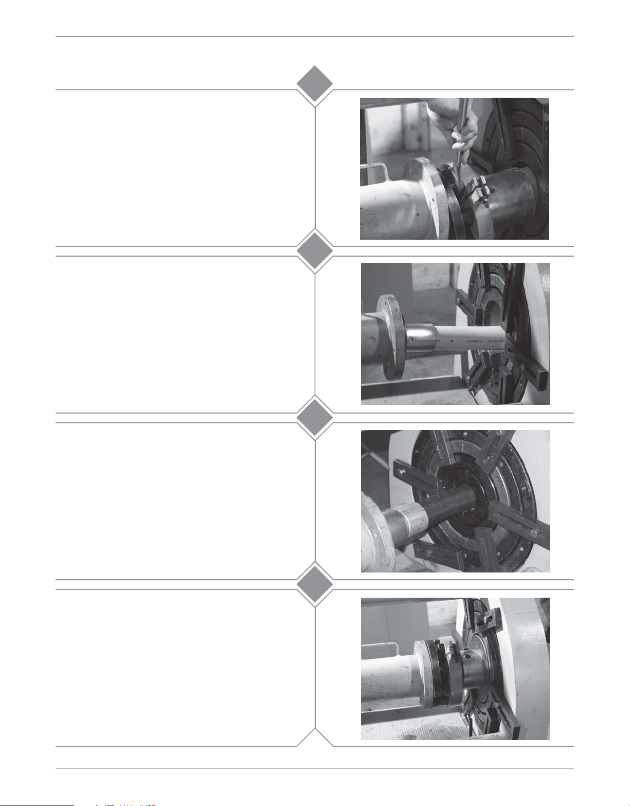
Ensuring that all of the jackscrews have been
threaded completely into the collar, install the collar
with jackscrews between the ferrule and the flange.
Position it so that the flat side of the collar is next to
the ferrule and the jackscrews are closest to the
flange lining up with the bolt holes. Secure both
collar halves with the “T” bolt.
Section 3
1-1/4" through 4" Standard & Long Flanged Holedall Swaged Couplings using Collar with Jack Screws
customer service
8a
3
800•355•1991
Page 24
100 Ton Ram Instruction Manual
Extend all of the jackscrews so that they are
contacting the flange. With a wrench, tighten one
jackscrew one half turn. Moving to the jackscrew
opposite of the one just tightened, tighten it one half
turn. Moving to the jackscrew immediately to the
right of the first one tightened, tighten it one half
turn. Moving to the jackscrew opposite of the one
just tightened, tighten it one half turn. Keep
repeating this process until all jackscrews are evenly
tensioned.
Lifting up the hose, insert one die half under the
hose. Lower the hose so that it rests on the die.
Insert the other die half. Make sure that the seams
of the die do not line up with the seams on the die
holders.
8b
9a
While holding the die in place with one hand, place
one of the tie down bars over the die so that it does
not come out of the die holder unexpectedly. Secure
the tie down bar by tightening the bolt.
Move the directional control lever to the “Forward”
position and depress the button on the remote.
Advance the cylinder forward until the end of the
ferrule is near the die opening. Using a wooden
board or metal pipe, lift the ferrule up. Jog the
cylinder by depressing and releasing the button on
the remote. This will allow the ferrule to enter the
die slowly. After the ferrule has entered the die, stop
advancing the cylinder.
9b
10a
4 Section 3
1-1/4" through 4" Standard & Long Flanged Holedall Swaged Couplings using Collar with Jack Screws
customer service 800•355•1991
Page 25

100 Ton Ram Instruction Manual
Align the flange face with the pusher.
For 4" assemblies, the raised face on the flange will
fit into the recess of the 4" Main Pusher (M011-065).
For 1-1/4" - 3" assemblies ensure the flange face
and the pusher are flush.
Loosen the bolt on the tie down bar holding the die
in place. Move the tie down bar so that it clears the
collar. When this is done, snug the bolt on that tie
down bar.
10b
11a
Depress and hold the button on the remote until the
top of the ferrule (where welded to stem) is even
(flush) with the top of the die. Release the button.
Return the directional control lever to the
“NEUTRAL” position.
Note: If the gauge reads 10,000 PSI before swaging
is complete, stop. The ferrule or die used for that
hose end may be incorrect. Contact Dixon for
further assistance.
Loosen all of the jackscrews so that they clear the
flange. Loosen the nut on the “T” bolt so that the “T”
bolt moves easily out of its slot. Remove the collar
from between the flange and the ferrule.
11b
12
Section 3
1-1/4" through 4" Standard & Long Flanged Holedall Swaged Couplings using Collar with Jack Screws
customer service
800•355•1991
5
Page 26

100 Ton Ram Instruction Manual
Position a rubber sheet or pad under the die bed.
Slowly
slide the hose towards the pusher. When the
die clears the die holder, one or both halves may fall
to the floor. If one half remains on the ferrule, tap it
with a mallet until it releases. If both halves remain
on the ferrule, it may require the halves be pried
apart at the seam.
Loosen the bolt(s) on the tie down bar(s) and move
the tie down bar(s) so that they clear one die bed
spacer. Tighten any bolt just loosened. Remove the
die bed spacer one half at a time. Repeat this
process for each die bed spacer to be removed.
Remove only enough die bed spacers to allow the
flange to pass through.
13a
13b
Wipe excess lubricant from hose and ferrule. Bring
hose with stem and ferrule back through die bed.
13c
6 Section 3
1-1/4" through 4" Standard & Long Flanged Holedall Swaged Couplings using Collar with Jack Screws
customer service 800•355•1991
Page 27

Section 4
100 Ton Ram Operating Instructions
for
RSTxxxNOS Stems
with
GASxxxxNOS Ferrules
Dixon Valve & Coupling Company
800 High Street • Chestertown, MD 21620
ph: 800•355•1991 fax: 800•283•4966
www.dixonvalve.com
Page 28

Page 29

100 Ton Ram Instruction Manual
Install the required die holders ensuring that the
seams between the die holder halves do not line up.
The die holders are designed to fit one inside the
other.
A guideline for selecting die holders is:
M012-001 1-1/4" - 3" I.D. hose
M012-002 4" - 6" I.D. hose
Caution!
Secure the die holders with tie down bars to prevent
the die holders from slipping out of the die bed
unexpectedly.
Install the 4" Main Pusher (M011-065) by sliding it
onto the rod cam of the ram cylinder. Make sure
that the pusher is all the way on the rod cap.
Never use a swaging die as a die holder!
1
2
Accurately measure the hose O.D. with a diameter
tape. Each end of the hose should be measured to
guarantee the correct ferrule and die selection.
Select the correct ferrule and die based upon the
hose free O.D. just measured from the die chart.
Make sure the hose end is cut square. If the hose is
to be static grounded, follow hose manufacturers
procedure for proper static grounding.
Slide the ferrule all the way onto the hose. Place a
mark on the hose at the end of the ferrule. Move the
ferrule 1/8" from the mark just made towards the
end of the hose. Place a second mark on the hose
at the end of the ferrule.
3
4
RSTxxxNOS Stems with GASxxxxNOS Ferrules
customer service 800•355•1991
1Section 4
Page 30

100 Ton Ram Instruction Manual
Lubricate the O.D. of the stem and the I.D. of the
hose with Dixon lubricant or equivalent. Insert the
end of the fitting into the hose. Assemble the ferrule
onto stem by sliding turned over portion of ferrule
past notched section of stem collar. Rotate ferrule
90° (1/4 turn). With ferrule and stem engaged,
continue installing stem until ferrule reaches the
second mark on the hose.
Lubricate the outside of the ferrule with Crisco®
(recommended) or high viscosity oil or heavy duty
grease.
5
6
Lubricate the I.D. of both die halves with Crisco®
(recommended) or high viscosity oil or heavy duty
grease.
Lifting up the hose, insert one die half under the
hose. Lower the hose so that it rests on the die.
Insert the other die half. Make sure that the seams
of the die do not line up with the seams on the die
holders.
7
8
2 Section 4
RSTxxxNOS Stems with GASxxxxNOS Ferrules
customer service
800•355•1991
Page 31

100 Ton Ram Instruction Manual
Install appropriate size spacer ring over the threads
of the stem so that it contacts the ferrule. The
spacer rings are listed as follows:
9
1-1/2"
Insert the stem into the pusher so that the spacer
ring just installed contacts the pusher.
1½" M011-112
2" M011-113
3" M011-115
Put the directional control lever in the “FORWARD”
position. Advance the cylinder forward until the end
of the ferrule is near the die opening. Using a
wooden board or metal pipe, lift the ferrule up. Jog
the cylinder by depressing and releasing the button
on the remote. This will allow the ferrule to enter the
die slowly without contacting the die face.
RST150SPACE
2"
RST200SPACE
3"
RST300SPACE
10
11
Depress and hold the button on the remote until the
pusher meets the die face. When the extension
contacts the die, release the button. Move the
directional control lever to the “NEUTRAL” position.
Note:
The spacer ring will enter the die.
Note: If the gauge reads 10,000 PSI before swaging
is complete, stop. The ferrule or die used for that
hose end may be incorrect. Contact Dixon for
further assistance.
RSTxxxNOS Stems with GASxxxxNOS Ferrules
customer service 800•355•1991
12
3Section 4
Page 32

100 Ton Ram Instruction Manual
Wipe excess lubricant from hose and ferrule. Bring
hose with stem and ferrule back through die bed.
13
4 Section 4
RSTxxxNOS Stems with GASxxxxNOS Ferrules
customer service
800•355•1991
Page 33

Section 5
100 Ton Ram Operating Instructions
for
Cam & Groove
Holedall Couplings
Dixon Valve & Coupling Company
800 High Street • Chestertown, MD 21620
ph: 800•355•1991 fax: 800•283•4966
www.dixonvalve.com
Page 34

Page 35

100 Ton Ram Instruction Manual
Install Main Pusher (M011-065) on cylinder rod cap.
Make sure that the pusher is fully installed on the
rod cap.
Install the Cam & Groove pusher necessary to do
the size and style of coupling to be swaged into the
Main Pusher (M011-065).
Additional pushers may be required.
Reference the chart at the end of this section for
proper pusher selection.
1
2
Install the required die holders ensuring that the
seams between the die holder halves do not line up.
The die holders are designed to fit one inside the
other.
A guideline for selecting die holders is:
DH6-003 1/4" - 1" I.D. hose
M012-002 4" - 6" I.D. hose
M012-003 6" - 8" I.D. hose
M012-004 8" - 10" I.D hose
Caution!
Secure the die holders with tie down bars to prevent
the die holders from slipping out of the die bed
unexpectedly.
Never use a swaging die as a die holder!
3a
3b
Cam & Groove Holedall Couplings
customer service 800•355•1991
1Section 5
Page 36

100 Ton Ram Instruction Manual
Accurately measure the hose O.D. with a diameter
tape. Each end of the hose should be measured to
guarantee the correct ferrule and die selection.
Select the correct ferrule and die based upon the
hose free O.D. just measured from the die chart.
Make sure that the hose end is cut square. If the
hose is to be static grounded, follow hose
manufacturers procedure for proper static
grounding.
4
5
Align the end of the hose with the stem shoulder i
mark the hose at the end of the stem
Place a mark on the outside of the ferrule that
corresponds with the
center
of one of the turned
over sections of the ferrule. This mark will act a
guide for correct engagement with the stem collar.
When using the Notched Stem and Ferrule system
these guidelines must be followed:
A. Before stem insertion, assemble the ferrule onto
the stem by sliding the turned over portion of the ferrule
past the notched sections of the stem collar. Rotate the
ferrule 90° (1/4 turn).
B. Before starting the swaging process, make sure
that the turned over portion of the ferrule and the collar
are fully engaged.
C. For “C” style couplings (requiring spacer rings),
make sure that the two ring halves meet over the turned
over portion of the ferrule which should be under the cam
arms.
6
7
2 Section 5
Cam & Groove Holedall Couplings
customer service 800•355•1991
Page 37

100 Ton Ram Instruction Manual
Cut the hose end square and if the assembly
requires static grounding, follow the hose
manufacturer’s procedure for proper static
grounding. Lubricate the hose I.D. and the O.D. of
the stem with Dixon Coupling Lubricant or
equivalent. Insert the Cam and Groove fitting with
ferrule onto the hose until the ferrule is even with the
mark closest to the hose end. This is the second
mark made on the hose.
Bring the hose with the stem and ferrule through the
die bed. Insert the coupling into or onto the pusher
(depending upon coupling style). Make sure that
there is sufficient room between the die holders and
the end of the ferrule to comfortably insert the die
halves into the die holders.
8
9
Lubricate the outside of the ferrule with Crisco®
(recommended) or high viscosity oil or heavy duty
grease.
Lubricate the I.D. of both die halves with Crisco®
(recommended) or high viscosity oil or heavy duty
grease.
10a
10b
Cam & Groove Holedall Couplings
customer service 800•355•1991
3Section 5
Page 38

100 Ton Ram Instruction Manual
Lifting up the hose, insert one die half under the
hose. Lower the hose so that it rests on the die.
Insert the other die half. Make sure that the seams
of the die do not line up with the seams on the die
holders.
While holding the die in place with one hand, place
one of the tie down bars over the die so that it does
not come out of the die holder unexpectedly. Secure
the tie down bar by tightening the bolt.
11a
11b
For style "C" couplings go to step 12.
For style "E" couplings go to step 13.
4 Section 5
Cam & Groove Holedall Couplings
customer service 800•355•1991
Page 39

100 Ton Ram Instruction Manual
For “C” style couplings requiring spacer rings:
Release both cam arms.
12a
12b
Remove the gasket from the coupler.
Put the spacer rings between the ferrule and coupler
head, making sure that the two ringhalves meet over
the turned over portion of the ferrule.
12c
12d
Insert the proper pusher into the coupler (reference
the chart at the end of this section for proper pusher
selection).
Cam & Groove Holedall Couplings
customer service 800•355•1991
5Section 5
Page 40

100 Ton Ram Instruction Manual
Check the ferrule engagement with the stem collar.
The mark on the ferrule (
positioned under the cam arm.
Move the directional control lever to the
“FORWARD” position. Depress the button on the
remote and advance the cylinder until the end of the
ferrule is near the die opening. Using a wooden
board or metal pipe, lift the ferrule up. Jog the
cylinder by quickly depressing and releasing the
button on the remote. This will allow the ferrule to
enter the die slowly without contacting the die face.
Continue jogging the cylinder until the ferrule has
entered the die approximately one half inch.
from Step 6a) must
be
12e
12f
Loosen and move any tie down bars that may come
in contact with the coupler head. Depress and hold
the button on the remote until the spacer rings are
even with or about to contact the die face. Release
the button on the remote. Return the directional
control lever to the “NEUTRAL” position.
Note: If the gauge reads 10,000 PSI before swaging
is complete, stop. The ferrule or die used for that
hose end may be incorrect. Contact Dixon for
further assistance.
Move the directional control lever to the “REVERSE”
position. Depress and hold the button on the
remote retracting the cylinder until there is sufficient
room for the stem and ferrule to clear the die bed.
12g
12h
6 Section 5
Cam & Groove Holedall Couplings
customer service 800•355•1991
Page 41

100 Ton Ram Instruction Manual
Position a rubber sheet or pad under the die bed.
While holding the die in place with one hand, loosen
the bolt on the tie down bar and move the tie down
bar so that it clears the die.
Slowly
slide the hose
towards the pusher. When the die clears the die
holder, one or both halves may fall to the floor. If
one half remains on the ferrule, tap it with a mallet
until it releases. If both halves remain on the ferrule,
it may require the halves be pried apart at the seam.
Remove the spacer rings from the coupling. Wipe
off excess lubricant from hose and ferrule. Bring the
hose with stem and ferrule back through the die bed.
Reinstall the gasket. Close the cam arms.
12i
12j
Note: Remove spacer ring from the 1-1/2" size only.
Cam & Groove Holedall Couplings
customer service 800•355•1991
7Section 5
Page 42

100 Ton Ram Instruction Manual
For “E” style couplings:
Check the ferrule for proper alignment. Ensure that
the mark on the ferrule (from Step 6b) is in the
center of the stem collar.
Move the directional control lever to the
“FORWARD” position. Depress the button on the
remote and advance the cylinder until the end of the
ferrule is near the die opening. Using a wooden
board or metal pipe, lift the ferrule up. Jog the
cylinder by quickly depressing and releasing the
button on the remote. This will allow the ferrule to
enter the die slowly without contacting the die face.
Continue jogging the cylinder until the ferrule has
entered the die approximately 1-1/2"
13a
13b
Move any tie down bars from the die that may come in
contact with the pusher. While holding the hose and
coupling up against the pusher, depress the button on
the remote. Once the ferrule has started to be reduced
(approximately 1/3 the way) it is no longer necessary for
the operator to hold the hose. Continue the swage until
the pusher contacts the die face. When this occurs,
release the button on the remote and move the
directional control lever to the “NEUTRAL” position.
Note: If the gauge reads 10,000 PSI before swaging
is complete, stop. The ferrule or die used for that
hose end may be incorrect. Contact Dixon for
further assistance.
Move the directional control lever to the “REVERSE”
position. Depress and hold the button on the remote
retracting the cylinder until there is sufficient room
for the stem and ferrule to clear the die bed.
13c
13d
8 Section 5
Cam & Groove Holedall Couplings
customer service 800•355•1991
Page 43

100 Ton Ram Instruction Manual
Position a rubber sheet or pad under the die bed.
While holding the die in place with one hand, loosen
the bolt on the tie down bar and move the tie down
bar so that it clears the die.
Slowly
slide the hose
towards the pusher . When the die clears the die
holder, one or both halves may fall to the floor. If
one half remains on the ferrule, tap it with a mallet
until it releases. If both halves remain on the ferrule,
it may require the halves be pried apart at the seam
Wipe excess lubricant from hose and ferrule. Bring
hose with stem and ferrule back through die bed.
13e
13f
Cam & Groove Holedall Couplings
customer service 800•355•1991
9Section 5
Page 44

100 Ton Ram Instruction Manual
Pushers and Spacer Rings For Cam & Groove
Size Description Part Number
1”
1 1/2”
2”
3”
4”
Type “E” Pusher
Type “C” Pusher
Type “E” Pusher
Type “C” Pusher
Spacer Ring
Type “E” Pusher
Type “C” Pusher
Type “E” Pusher
Type “C” Pusher
Type “E” Pusher
Type “C” Pusher
100PUSHGCRC
100PUSHCGRC
100PUSHCG15E
100PUSHCG15 (
150CGSPACE
100PUSHCE2
100PUSHCG2
100PUSHCG3
100PUSHCG2
100PUSHCG4E
100PUSHCG4C
Note: Spacer Rings are to be used with Type “C” Couplings ONLY.
DO NOT use Spacer Rings with Type “E” Couplings, or bodily injury may result.
2 pieces
)
Dixon Valve and Coupling Company recommends that all
hose assemblies be tested as recommended by the Rubber Manufacturers Association.
10 Section 5
Cam & Groove Holedall Couplings
customer service 800•355•1991
Page 45

Section 6
100 Ton Ram Operating Instructions
for
Boss Ground Joint
Holedall Couplings
Dixon Valve & Coupling Company
800 High Street • Chestertown, MD 21620
ph: 800•355•1991 fax: 800•283•4966
www.dixonvalve.com
Page 46

Page 47

100 Ton Ram Instruction Manual
Install the 4" Main Pusher (M011-065) by sliding it
onto the rod cap of the ram cylinder. Make sure that
the pusher is all the way on the rod cap. Install the
appropriate adapter pusher (by coupling size) into
the main pusher.
Accurately measure the hose O.D. with a diameter
tape. Each end of the hose should be measured to
guarantee the correct ferrule and die selection.
Select the correct ferrule and die based upon the
hose free O.D. just measured from the chart.
1
2
Assuring that the hose end is cut square, chamfer
the I.D. of the hose 1/8" at a 45° angle. This will aid
in stem insertion. If the hose is to be static
grounded, follow hose manufacturers procedure for
proper static grounding.
Hold the ferrule against the stem collar (sizes 1-1/2"
- 3" only). Using a small ruler or other measuring
devise, insert it between the stem and ferrule until it
contacts the stem collar. Measure the depth at the
end of the ferrule. Place a mark on the hose (the
hose end to be assembled) that corresponds with
this measurement.
3
4a
Boss Ground Joint Holedall Couplings
customer service
800•355•1991
1Section 6
Page 48

100 Ton Ram Instruction Manual
Lubricate the I.D. of the hose and the O.D. of the
stem (as well as possible) with Dixon Coupling
Lubricant or equivalent. Insert the stem all the way
until the mark on the hose (
end of the ferrule.
Bring the hose with the stem and ferrule through the
die bed. Position the wing nut (or spud) as close to
the pusher as possible. Make sure that there is
sufficient room between the die holders and the end
of the ferrule to comfortably insert the die halves into
the die holders.
from Step 4a
) is at the
4b
5
Install the required die holders ensuring that the
seams between the die holder halves do not line up.
The die holders are designed to fit one inside the
other.
A guideline for selecting die holders is:
DH6-003 1/4" - 1" I.D. hose
M012-001 1-1/4" - 3" I.D. hose
M012-002 4" - 6" I.D. hose
M012-003 6" - 8" I.D. hose
M012-004 8" - 10" I.D hose
Caution!
Secure the die holders with tie down bars to prevent
the die holders from slipping out of the die bed
unexpectedly.
Never use a swaging die as a die holder!
6a
6b
2 Section 6
Boss Ground Joint Holedall Couplings
customer service 800•355•1991
Page 49

100 Ton Ram Instruction Manual
7a
Lubricate the outside of the ferrule with Crisco
®
(recommended) or high viscosity oil or heavy duty
grease.
Lubricate the I.D. of both die halves with Crisco
®
(recommended) or high viscosity oil or heavy duty
grease.
7b
8a
Lifting up the hose, insert one die half under the
hose. Lower the hose so that it rests on the die.
Insert the other die half. Make sure that the seams
of the die do not line up with the seams on the die
holders.
While holding the die in place with one hand, place
one of the tie down bars over the die so that it does
not come out of the die holder unexpectedly.
Secure the tie down bar by tightening the bolt.
8b
Boss Ground Joint Holedall Couplings
customer service
800•355•1991
3Section 6
Page 50

100 Ton Ram Instruction Manual
Move the directional control lever to the
“FORWARD” position and depress the button on the
remote. Advance the cylinder forward until the end
of the ferrule is near the die opening. Using a
wooden board or metal pipe, lift the ferrule up. Jog
the cylinder by depressing and releasing the button
on the remote. This will allow the ferrule to enter the
die slowly. After the ferrule has entered the die, stop
advancing the cylinder.
Align the wing nut (or spud) with the pusher
ensuring they are flush with each other. Jog the
cylinder forward until pressure begins to register on
the gauge. Leave the directional control lever in the
“FORWARD” position. Check the alignment
between pusher and wing nut (or spud). If any
adjustment is necessary, do it now.
9a
9b
Reposition the tie down bars on the die face so that
the wing nut (or spacer) will clear.
Depress and hold the button on the remote until the
wing nut (or spacer) contacts the die face. Release
the button. Return the directional control lever to the
“NEUTRAL” position.
Note! For 3/4" and 1" couplings having the ferrule
crimped on, stop the swage when the crimped area
of the ferrule begins to enter the die.
Note: If the gauge reads 10,000 PSI before swaging
is complete, stop. The ferrule or die used for that
hose end may be incorrect. Contact Dixon for
further assistance.
9c
10a
4 Section 6
Boss Ground Joint Holedall Couplings
customer service 800•355•1991
Page 51

100 Ton Ram Instruction Manual
Move the directional control lever to the “REVERSE”
position and depress the button on the remote.
Retract the cylinder until there is sufficient room for
the stem and ferrule to clear the die bed.
Position a rubber sheet or pad under the die bed.
Slowly
slide the hose towards the pusher. When the
die clears the die holder, one or both halves may fall
to the floor. If one half remains on the ferrule, tap it
with a mallet until it releases. If both halves remain
on the ferrule, it may require the halves be pried
apart at the seam.
10b
11a
Wipe excess lubricant from hose and ferrule. Bring
hose with stem and ferrule back through die bed.
11b
Boss Ground Joint Holedall Couplings
customer service
800•355•1991
5Section 6
Page 52

Page 53

Section 7
100 Ton Ram Operating Instructions
for
Converting from
Swaging to Internal Expansion
Dixon Valve & Coupling Company
800 High Street • Chestertown, MD 21620
ph: 800•355•1991 fax: 800•283•4966
www.dixonvalve.com
Page 54

Page 55

100 Ton Ram Instruction Manual
Remove any swaging pusher from the ram cylinder
rod cap.
Position a rubber mat under the die bed. Position
the tie down bars so that only one die bed spacer is
clear. Remove the die bed spacer from die bed.
Repeat this process until all die bed spacers have
been removed from the die bed.
1
2
Caution! Die bed spacers are heavy. Remove the
die bed spacers one half at a time.
Install IX Master Plate onto outside of ram die bed.
Position the bolt holes at the 3 o’clock and 9 o’clock
positions. Secure with straps and bolts by
positioning the straps on the inside of the die bed.
Tighten the nuts on the bolts.
Note! It may be required to turn one or more of the
large nuts on the outside of the die bed. If the IX
Master Plate will not fit into the die bed opening,
check the nuts to see if the flat on the nut is facing
the die bed opening. If not, turn the nut until the flat
is facing the opening.
Move the directional control lever to the
“FORWARD” position. Depress the button on the
remote and extend the ram cylinder fully. Release
the button on the remote and move the directional
control lever to the “NEUTRAL” position. Bring the
IX Master Bar through the opening in the IX Master
Plate, male thread end first. Thread the male thread
on the IX Master Bar into the female thread of the
rod cap. Continue to thread the bar in until the
shoulder behind the thread on the bar contacts the
face of the rod cap.
3
4
Converting from Swaging to Internal Expansion
customer service 800•355•1991
1Section 7
Page 56

Page 57

Section 8
100 Ton Ram Operating Instructions
for
Internal Expansion of
Carbon Steel & Stainless Steel Couplings
Dixon Valve & Coupling Company
800 High Street • Chestertown, MD 21620
ph: 800•355•1991 fax: 800•283•4966
www.dixonvalve.com
Page 58

Page 59

100 Ton Ram Instruction Manual
(refer to the
Converting the 100 Ton Ram from Swaging to Internal Expansion
Before you begin, move the directional control lever
to the "FORWARD” position, depress the button on
the remote and fully extend the ram cylinder. Return
the directional control lever to the “NEUTRAL”
position. Select the proper Pull Rod.
For 1" through 1 1/2" use
through 4" use
For 5" and 6" use
25RODLARGE
001-0083
25RODSMALL
For 2"
Screw the short threaded end of the rod or the rod
adapter into the IX Master Bar.
Select the corresponding Adapter Plate(s) for the
size and type of fitting you are installing. For certain
sizes and styles of couplings, multiple adapter plates
may be required.
The 2" through 4" adapters have two recesses. The
small diameter recess is to be used with stems
having NPT, Victaulic or Plain end. The larger
diameter recess is used for stems with the “Heavy
Duty / California Style” end. The 6" adapter is built
into the IX Master plate (001-0072).
section of the instruction manual)
1
2
Lubricate the inside of the stem with Crisco®
(recommended) or high viscosity oil or heavy duty
grease.
Lubricate the O.D. of the plug with Crisco®
(recommended) or high viscosity oil or heavy duty
grease.
3a
3b
Internal Expansion of Carbon Steel & Stainless Steel Couplings
customer service
800•355•1991
1Section 8
Page 60

100 Ton Ram Instruction Manual
Slide the adapter(s) over the pull rod and into the
recess of the IX Master Plate. While holding the
adapter(s) in place with one hand, slide the stem
over the pull rod and into the recess of the adapter
plate with the connection side of the stem facing the
ram. While holding the adapter(s) and stem in place
with one hand, screw on (or slide) the IX plug, small
end first, onto the pull rod and into the shank of the
stem. For 2" and above screw the retaining nut on
until it contacts the plug. Move the stem slightly to
allow for slack and hand tighten the plug or nut until
it is snug. Lubricate the rest of the O.D. of the plug.
Accurately measure the hose O.D. with a diameter
tape. Select the correct IX ferrule from the current
Dixon Price List based upon the hose O.D. just
measured.
4
5
Note!
Always measure both hose ends for accurate
ferrule selection.
Make sure the hose end is cut square. Slide the
ferrule over the hose until the turned over end of the
ferrule contacts the end of the hose. Place a mark
on the hose at the junction of the ferrule and hose.
Move the ferrule away from the hose end 1/4" and
place another mark at the junction of the hose and
ferrule. This will ensure that the proper rubber
displacement or pocked is maintained during the
expansion process.
Slide the hose with the ferrule on over the IX plug
and shank until the ferrule contacts the shoulder of
the stem. Make sure you align the ferrule with the
second mark from
has been maintained.
Step 8
. Make sure the pocket
6
7
Important!
rubber to displace into, damage may occur to the
stem, ferrule and / or hose.
2 Section 8
If there is insufficient pocket for the
Internal Expansion of Carbon Steel & Stainless Steel Couplings
customer service 800•355•1991
Page 61

100 Ton Ram Instruction Manual
10
Place a rubber sheet or pad under the IX Master
plate. Move the directional control lever to the
“REVERSE” position. While holding the hose and
ferrule firmly against the stem shoulder, engage the
ram by depressing the button on the remote. The
internal expansion operation is complete when the
expansion plug is pulled completely through the
stem (see
on the remote. Visually inspect the coupling and
clean excess lubricant from the stem I.D.
Note: If the gauge reads 10,000 PSI before swaging is complete, stop.
Important!
below). Release the button
The ferrule or die used for that hose end may be incorrect.
Contact Dixon for further assistance.
Important! When the pressure gauge drops to zero, release the button on the remote.
Pull the assembly off of the plug and, at the same time, remove the adapter(s) from the IX Master Plate.
* Assembly procedure for 2-1/2" & 4" threaded male stems:
In order to prevent possible thread collapse on the 2-1/2" & 4" male NPT stems (carbon steel) during
installation, it is recommended that a female threaded adapter be installed prior to installation. The adapter part
number for 2-1/2" is M011-384 and 4" is M011-385. Following is the procedure for installation:
1. Lubricate stem I.D. and small end of expansion plug.
2. Thread M011-384 or M011-385 onto threads of the male stem
hand tight
only
!
3. Slide stem over pull rod thread adapter first.
4. Seat M011-384 or M011-385 into
outer
recess of the adapter.
5. Follow normal IX procedure.
6. When assembly is removed from the adapter, remove M011-384 or M011-385 and clean the stem I.D. of
excess lubricant.
Procedure changes for stainless steel food grade couplings
1.
2.
Step 3a
Step 3b
. - Must use Crisco ® for lubricant.
. - Must use Crisco ® for lubricant.
3. When IX plug is removed and cleaned of lubricant, the visible lines on the plug are deposits of stainless
steel. Remove the deposits with 200 - 400 grit wet / dry sandpaper. This is to be done after every pull.
4. Make sure the expansion plug to be used has “FD” in the part number (stamped on the large end of the
plug). If “FD” is not in the part number DO NOT USE IT!
Internal Expansion of Carbon Steel & Stainless Steel Couplings
customer service
800•355•1991
3Section 8
Page 62

Page 63

Section 9
100 Ton Ram Operating Instructions
for
Internal Expansion of
H520 Couplings
Dixon Valve & Coupling Company
800 High Street • Chestertown, MD 21620
ph: 800•355•1991 fax: 800•283•4966
www.dixonvalve.com
Page 64

Page 65

100 Ton Ram Instruction Manual
(refer to the
Converting the 100 Ton Ram from Swaging to Internal Expansion
Before you begin, move the directional control lever
to the "FORWARD” position, depress the button on
the remote and fully extend the ram cylinder. Return
the directional control lever to the “NEUTRAL”
position. Select the proper Pull Rod.
For 1" through 1 1/2" use
through 4" use
25RODLARGE
25RODSMALL
For 2"
Screw the short threaded end of the rod or the rod
adapter into the IX Master Bar.
Install the Master IX Adapter (001-0072) into the Die
Bed Plate (0010-001). Secure in place using two
Adapter Straps (001-0072A) and 3/4" - 10 UNC x 8"
rods.
section of the instruction manual)
1
2
Install the 100ROSTPA into the Master IX Adapter
opening and secure with Adapter Straps (001-
0072A) and two 1/2" - 13 UNC Hex Bolts 1-5/8"
long.
Select the corresponding Thrust Plate for the size
fitting you are installing. Assuring that the recess is
facing outward toward the operator, slide the Thrust
Plate over the Pull Rod until it reaches the
100ROSTPA. Align the holes in the Thrust Plate
with the dowel pins on the 100ROSTPA and slide
the Thrust Plate over the pins. Tighten the wing nut
to lock in place.
3
4
Internal Expansion of H520 Couplings
customer service
800•355•1991
1Section 9
Page 66

100 Ton Ram Instruction Manual
Slide the stem over the Pull Rod and into the recess
of the Thrust Plate with the connection side of the
stem facing the ram. For male stems, insert the hex
into the recess of the Thrust Plate. For female
stems, insert the first hex into the Thrust Plate so
that the second hex will fit into the recess of the
Thrust Plate.
Note! There is no need to lubricate the plug or
stem. The stems are pre-lubricated at the factory
Screw or slide the IX plug, small end first, onto the
Pull Rod and into the shank of the stem. For 2” and
above screw the retaining nut on until it contacts the
plug. Move the stem slightly to allow for slack and
hand tighten the plug or nut until it is snug.
.
5
6
Accurately measure the hose O.D. with a diameter
tape. Select the correct Holedall Petroleum Ferrule
from the DPL based upon the Hose O.D. just
measured.
Note! Always measure both hose ends for accurate
ferrule selection.
Make sure the hose end is cut square. Slide the
ferrule over the hose until the turned over end of the
ferrule contacts the end of the hose. Place a mark
on the hose at the junction of the ferrule and hose.
Move the ferrule away from the hose end 1/8” and
place another mark at the junction of the hose and
ferrule. This will insure that the proper rubber
displacement or pocket is maintained during the
expansion process.
7
8
2 Section 9
Internal Expansion of H520 Couplings
customer service
800•355•1991
Page 67

100 Ton Ram Instruction Manual
Slide the hose with the ferrule on over the shank
until the ferrule contacts the shoulder of the stem.
Make sure you align the ferrule with the second
mark from step 6. Make sure the pocket has been
maintained.
Important! If there is an insufficient pocket for the
rubber to displace into, damage may occur to the
stem, ferrule, and /or hose.
While holding the hose and ferrule firmly against the
stem shoulder, engage the ram cylinder by stepping
on the foot pedal (or depressing the “ON” button on
the remote control.) The internal expansion
operation is complete when the hose and stem
assembly is pushed completely over the internal
expansion plug. Releas the foot pedal or “ON”
switch.
9
10
Note: If the gauge reads 10,000 PSI before internal expansion is complete, stop. Contact Dixon for further
assistance. During internal expansion never stand directly in front of the ram. Visually inspect the coupling.
Internal Expansion of H520 Couplings
customer service
800•355•1991
3Section 9
Page 68

Page 69

Section 10
100 Ton Ram
List of Parts and Attachments
Dixon Valve & Coupling Company
800 High Street • Chestertown, MD 21620
ph: 800•355•1991 fax: 800•283•4966
www.dixonvalve.com
Page 70

100 Ton Ram Instruction Manual
100 Ton Ram
Equipment to Swage 1 ¼" to 10" I.D. Hose Sizes
100 TONRAM “Mulcoram” including motor (115 volt) pump and bed plates 1 ¼" - 10"
External Swage Attachments
Please note that on some sizes, more than two attachments may be necessary. Read
carefully through all descriptions to determine which attachments are needed for your
applications. Please consult the Factory if you need more information.
M011-242 10" Pusher for all standard length stems with and without flange
M011-249 10" Pusher extension for all plain, threaded and grooved end stems
(for both standard and long length)
M011-256 10" Spacer for all flanged assemblies(for both standard and long length)
M011-254 10" Pusher for all long length stems with and without flange
M011-253 10" Pusher extension for all plain, threaded, grooved and flanged end long
length stems
M011-101 8" Pusher for all plain, threaded, grooved and flanged end standard and long
length stems.
M011-117 8" Pusher extension for all plain, threaded, grooved and flanged end long
length stems.
M011-118 8" Spacer for all flanged assemblies (for both standard and long length)
M011-070 6" Pusher for all plain, threaded, grooved and flanged end standard and long
length stems.
M011-073 6" Pusher extension for all plain, threaded, grooved and flanged end long
length stems.
M011-132 6" Spacer for all flanged assemblies(for both standard and long length)
M011-079 5" Adapter Pusher (fits into 6 Pusher). For all plain, threaded, grooved and
flanged end standard and long length stems.
M011-076 5" Adapter Pusher extension for all plain, threaded, grooved and flanged
end long length stems
Parts & Attachments
customer service 800•355•1991
1Section 10
Page 71

100 Ton Ram Instruction Manual
M011-135 5" Spacer for all flanged assemblies(for both standard and long length)
M011-065 4" Pusher for all stems
M011-131 4" Spacer for all flanged assemblies
DH6-003 Die Holder needed for 1¼" to 3"
M011-115 3" Adapter Pusher (fits into 4" Pusher). For all stems.
M011-158 3" Spacer for all flanged assemblies
M011-114 2 ½" Adapter Pusher (fits into 4" Pusher). For all stems
M011-274 2 ½" Spacer for all flanged assemblies
M011-113 2" Adapter Pusher (fits into 4" Pusher)
M011-275 2" Spacer for all flanged assemblies.
M011-112 1 ½" Adapter Pusher (fits into 4" Pusher)
M011-111 1 ¼" Adapter Pusher (fits into 4" Pusher)
2
Parts & Attachments
customer service 800•355•1991
Section 10
Page 72

100 Ton Ram Instruction Manual
100 Ton Ram
Equipment to Swage 1" through 4" Cam & Groove
M011-065 4" Pusher (Needed For All Sizes)
100PUSHCG4E Pusher for 4" E
100PUSHCG4C Pusher for 4" C
100PUSHCG3 Pusher for 3" E (fits on 100PUSHCG2)
100PUSHCG2 Pusher for 2" C and E and 3" C (Also use with 100PUSHCGRC
and RE100PUSH)
100PUSHCG15 Pusher for 1 ½" C - Consists of the following:
100PUSHCG15A 1 ½" Pusher Adapter
RC150PUSHB 1 ½" Pusher
100PUSHCGRC Pusher for 1" C & G Couplers (fits inside the 100PUSHCG2)
RE100PUSH Pusher for 1" E (use with 100PUSHCG2)
RST300SPACE 3" Spacer Ring for NOS Ferrules (use with 100PUSHCG3)
RST200SPACE 2" Spacer Rings for NOS Ferrules (use with 100PUSHCG2)
RST150SPACE 1 ½" Spacer Rings for NOS Ferrules (use with 100PUSHCG15E)
150CGSPACE * Spacer Rings for 1 ½" C
100CGSPACE * Spacer Rings for 1" C
Swage Dies Not Included
* Future designs may not require Spacer Rings.
Contact the Factory for more information.
Parts & Attachments
customer service 800•355•1991
3Section 10
Page 73

100 Ton Ram Instruction Manual
Holedall Dies
Range
Min Max
x
3/4
9/16
x
2
1-7/8
10
13
x
1-11/16
x
4-5/16
x
7
x
x
6-1/2
9-1/2
12-3/8
4-1/2
6-15/16
12-15/16
10
16
x
x
x
x
x
4-1/4
6-7/16
9-1/2
12-3/8
15-1/2
2-1/8
4-9/16
* Dies will be invoiced for full selling price when shipped, credit will be issued when returned
for full selling price less rental charge. All freight charges are to be paid by Customer. All dies
are to be returned within 30 days.
4
Parts & Attachments
customer service 800•355•1991
Section 10
Page 74

100 Ton Ram Instruction Manual
100 Ton Ram
Equipment to Internally Expand 1" - 6" I.D. Hose
For Use with Steel IX Fittings
001-0086 Master IX Bar Adapter(Needed For All Sizes)
001-0083 IX Bar for 5" - 6"
001-0072 IX Master Plate (Needed For All Sizes)(this part is also 6" IX Adapter)
25RODLARGE IX Bar for 2" - 4" - Consists of the following:
25RDLG-A Large Rod for only 25TONRAM
25RDLG-B Nut only for 15 & 25 TON RAMS
25RODSMALL IX Bar for 1" and 1 ½" - Consists of the following:
25RDSML-A Small pull rod
25RDSML-B Small pull rod adapter
25RDSML-C Nut for Small Rod
001-0065 5" IX Adapter
001-0067 4" IX Adapter(Needed For All Sizes from 1 ¼" to 4")
M011-385 4" I.X. Adapter (Fits into 001-0067)
25ADAPT300 3" IX Adapter
25ADAPT250 2 ½" IX Adapter
M011-384 2 ½" IX Adapter (IXM40 Only). Must be used with 25ADAPT250
25ADAPT200 2" IX Adapter
25ADAPT150 1 ½" IX Adapter
25ADAPT125 1 ¼" IX Adapter
25ADAPT100 1" IX Adapter
Parts & Attachments
customer service 800•355•1991
5Section 10
Page 75

Equipment to Internally Expand 1" - 6" I.D. Hose (cont.)
For use with Steel IX and Holedall Petroleum Fittings
IXPLUG600 6" IX Plug
IXPLUG500 5" IX Plug
IXPLUG400 4" IX Plug
IXPLUG300 3" IX Plug
IXPLUG250 2 ½" IX Plug
100 Ton Ram Instruction Manual
100 Ton Ram
IXPLUG200 2" IX Plug
IXPLUG150 1 ½" IX Plug
IXPLUG125 1 ¼" IX Plug
IXPLUG100 1" IX Plug
6
Parts & Attachments
customer service 800•355•1991
Section 10
Page 76

100 Ton Ram Instruction Manual
100 Ton Ram
Equipment to Internally Expand “Flow Chief” Food Grade Fittings
001-0086 Master IX Bar Adapter (Needed For All Sizes)
001-0072 IX Master Plate (Needed For All Sizes)(this part is also 6" IX ADAPTER)
001-0067 4" IX Adapter (for male NPT) Needed For All Sizes from 1 ¼" to 4"
25RODLARGE IX Bar for 2" - 4" - Consists of the following:
25RDLG-A Large Rod for only 25TONRAM
25RDLG-B Nut only for 15 & 25 TON RAMS
25RODSMALL IX Bar for 1 ¼" and 1 ½" - Consists of the following:
25RDSML-A Small pull rod
25RDSML-B Small pull rod adapter
25RDSML-C Nut for Small Rod
25ADAPT300 3" IX Adapter (for male NPT)
25ADAPT250 2 ½" IX Adapter (for male NPT)
25ADAPT200 2" IX Adapter (for male NPT)
25ADAPT150 1 ½" IX Adapter (for male NPT)
PFADAPT400 4" IX Sanitary End Adapter (Tri Clover style)
PFADAPT300 3" IX Sanitary End Adapter (Tri Clover style)
PFADAPT250 2 ½" IX Sanitary End Adapter (Tri Clover style)
PFADAPT200 2" IX Sanitary End Adapter (Tri Clover style)
PFADAPT150 1 ½" IX Sanitary End Adapter (Tri Clover style)
PFADAPT150-3A 1 ½" 3A IX Sanitary End Adapter (Tri Clover style )
Parts & Attachments
customer service 800•355•1991
7Section 10
Page 77

100 Ton Ram Instruction Manual
100 Ton Ram
Equipment to Internally Expand "Flow Chief" Food Grade Fittings (cont.)
PFACNTA400 4" Bevel Seat Acme Nut AdapterMust buy PFADAPT400 to use this part.
PFACNTA300 3" Bevel Seat Acme Nut AdapterMust buy PFADAPT300 to use this part.
PFACNTA250 2 ½" Bevel Seat Acme Nut AdapterMust buy PFADAPT250 to use this part.
PFACNTA200 2" Bevel Seat Acme Nut AdapterMust buy PFADAPT200 to use this part.
PFACNTA150 1 ½" Bevel Seat Acme Nut AdapterMust buy PFADAPT150 to use this part.
IXFDPLG400 4" Food Plugs (for Stainless Steel Fittings)
IXFDPLG300 3" Food Plugs (for Stainless Steel Fittings)
IXFDPLG250 2 ½" Food Plugs (for Stainless Steel Fittings)
IXFDPLG200 2" Food Plugs (for Stainless Steel Fittings)
IXFDPLG150 1 ½" Food Plugs (for Stainless Steel Fittings)
IXFDPLG287 3" Food Plug for 3A Fittings
IXFDPLG187 2" Food Plug for 3A Fittings
IXFDPLG137 1 ½" Food Plug for 3A Fittings
8
Parts & Attachments
customer service 800•355•1991
Section 10
 Loading...