

Page 1
Section 6
100 Ton Ram Operating Instructions
for
Boss Ground Joint
Holedall Couplings
Dixon Valve & Coupling Company
800 High Street • Chestertown, MD 21620
ph: 800•355•1991 fax: 800•283•4966
www.dixonvalve.com
Page 2

Page 3
100 Ton Ram Instruction Manual
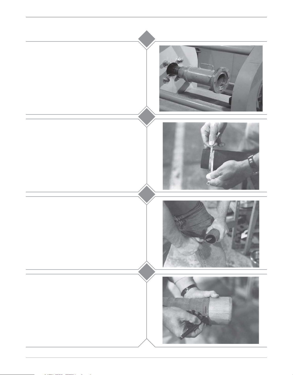
Install the 4" Main Pusher (M011-065) by sliding it
onto the rod cap of the ram cylinder. Make sure that
the pusher is all the way on the rod cap. Install the
appropriate adapter pusher (by coupling size) into
the main pusher.
Accurately measure the hose O.D. with a diameter
tape. Each end of the hose should be measured to
guarantee the correct ferrule and die selection.
Select the correct ferrule and die based upon the
hose free O.D. just measured from the chart.
1
2
Assuring that the hose end is cut square, chamfer
the I.D. of the hose 1/8" at a 45° angle. This will aid
in stem insertion. If the hose is to be static
grounded, follow hose manufacturers procedure for
proper static grounding.
Hold the ferrule against the stem collar (sizes 1-1/2"
- 3" only). Using a small ruler or other measuring
devise, insert it between the stem and ferrule until it
contacts the stem collar. Measure the depth at the
end of the ferrule. Place a mark on the hose (the
hose end to be assembled) that corresponds with
this measurement.
3
4a
Boss Ground Joint Holedall Couplings
customer service 800•355•1991
1Section 6
Page 4

100 Ton Ram Instruction Manual
Lubricate the I.D. of the hose and the O.D. of the
stem (as well as possible) with Dixon Coupling
Lubricant or equivalent. Insert the stem all the way
until the mark on the hose (
end of the ferrule.
Bring the hose with the stem and ferrule through the
die bed. Position the wing nut (or spud) as close to
the pusher as possible. Make sure that there is
sufficient room between the die holders and the end
of the ferrule to comfortably insert the die halves into
the die holders.
from Step 4a
) is at the
4b
5
Install the required die holders ensuring that the
seams between the die holder halves do not line up.
The die holders are designed to fit one inside the
other.
A guideline for selecting die holders is:
DH6-003 1/4" - 1" I.D. hose
M012-001 1-1/4" - 3" I.D. hose
M012-002 4" - 6" I.D. hose
M012-003 6" - 8" I.D. hose
M012-004 8" - 10" I.D hose
Caution!
Secure the die holders with tie down bars to prevent
the die holders from slipping out of the die bed
unexpectedly.
Never use a swaging die as a die holder!
6a
6b
2 Section 6
Boss Ground Joint Holedall Couplings
customer service 800•355•1991
Page 5

100 Ton Ram Instruction Manual
7a
Lubricate the outside of the ferrule with Crisco
®
(recommended) or high viscosity oil or heavy duty
grease.
Lubricate the I.D. of both die halves with Crisco
®
(recommended) or high viscosity oil or heavy duty
grease.
7b
8a
Lifting up the hose, insert one die half under the
hose. Lower the hose so that it rests on the die.
Insert the other die half. Make sure that the seams
of the die do not line up with the seams on the die
holders.
While holding the die in place with one hand, place
one of the tie down bars over the die so that it does
not come out of the die holder unexpectedly.
Secure the tie down bar by tightening the bolt.
8b
Boss Ground Joint Holedall Couplings
customer service 800•355•1991
3Section 6
Page 6

100 Ton Ram Instruction Manual
Move the directional control lever to the
“FORWARD” position and depress the button on the
remote. Advance the cylinder forward until the end
of the ferrule is near the die opening. Using a
wooden board or metal pipe, lift the ferrule up. Jog
the cylinder by depressing and releasing the button
on the remote. This will allow the ferrule to enter the
die slowly. After the ferrule has entered the die, stop
advancing the cylinder.
Align the wing nut (or spud) with the pusher
ensuring they are flush with each other. Jog the
cylinder forward until pressure begins to register on
the gauge. Leave the directional control lever in the
“FORWARD” position. Check the alignment
between pusher and wing nut (or spud). If any
adjustment is necessary, do it now.
9a
9b
Reposition the tie down bars on the die face so that
the wing nut (or spacer) will clear.
Depress and hold the button on the remote until the
wing nut (or spacer) contacts the die face. Release
the button. Return the directional control lever to the
“NEUTRAL” position.
Note! For 3/4" and 1" couplings having the ferrule
crimped on, stop the swage when the crimped area
of the ferrule begins to enter the die.
Note: If the gauge reads 10,000 PSI before swaging
is complete, stop. The ferrule or die used for that
hose end may be incorrect. Contact Dixon for
further assistance.
9c
10a
4 Section 6
Boss Ground Joint Holedall Couplings
customer service 800•355•1991
Page 7

100 Ton Ram Instruction Manual
Move the directional control lever to the “REVERSE”
position and depress the button on the remote.
Retract the cylinder until there is sufficient room for
the stem and ferrule to clear the die bed.
Position a rubber sheet or pad under the die bed.
Slowly
slide the hose towards the pusher. When the
die clears the die holder, one or both halves may fall
to the floor. If one half remains on the ferrule, tap it
with a mallet until it releases. If both halves remain
on the ferrule, it may require the halves be pried
apart at the seam.
10b
11a
Wipe excess lubricant from hose and ferrule. Bring
hose with stem and ferrule back through die bed.
11b
Boss Ground Joint Holedall Couplings
customer service 800•355•1991
5Section 6
 Loading...