

Dixie Chopper Pursuit 1832S, Pursuit 1836S, Pursuit 1836D, Pursuit 1844D Safety, Operation And Maintenance Manual
Page 1

2016 PURSUIT WALK-BEHIND
Safety, Operation, & Maintenance Manual
Pursuit 1832S, Single-Drive, 32” Cutting Unit
Pursuit 1836S, Single-Drive, 36” Cutting Unit
Pursuit 1836D, Dual-Drive, 36” Cutting Unit
Pursuit 1844D, Dual-Drive, 44” Cutting Unit
WARNING
Warning: If incorrectly used, this machine can cause severe injury. Those who use and
maintain this machine should be trained in its proper use, warned of its dangers, and must
read the entire manual before attempting to set up, operate, adjust,or service the machine.
700493
Page 2

CONTENTS
1
Introduction
2.1 Important ..........................................................................1
2.2 Product Identication .........................................................1
2.3 Serial Numbers ...................................................................1
2.4 Guidelines for the Disposal of Scrap Products .....................2
Safety
3.1 How to Operate Safely ....................................................... 3
Specications
4.1 Engine Specications .........................................................7
4.2 Dimensions and Weights ....................................................8
4.3 Mower Specication ........................................................10
4.4 Cutting Unit Specication ................................................10
4.5 Belt Specication .............................................................10
4.6 Recommended Lubricants ................................................ 11
4.7 Slopes .............................................................................. 11
4.8 Accessories ......................................................................11
4.9 Support Literature ............................................................11
Decals
5.1 Safety & Instruction Decals ............................................... 12
Controls
6.1 Mower Controls ...............................................................13
6.2 Ignition Switch ................................................................. 14
6.3 PTO Switch ......................................................................14
6.4 Hour Meter ...................................................................... 14
6.5 Throttle Lever ...................................................................14
6.6 Neutral Release ................................................................ 14
6.7 Parking Brake ...................................................................14
6.8 Pursuit 1836S Controls ....................................................15
6.9 Pursuit 1836D/1844D Controls ........................................16
Operation
7.1 Daily Inspection ................................................................17
7.2 Pursuit 1836S OPC System ............................................... 18
7.3 Pursuit 1836D/1844D OPC System ................................... 19
7.4 Operating Procedure ........................................................20
7.5 Starting The Engine ..........................................................21
7.6 To Stop The Engine .......................................................... 21
7.7 Pursuit 1832/1836S Driving ..............................................22
7.8 Pursuit 1836D/1844D Driving ...........................................23
7.9 Mowing ........................................................................... 24
7.10 Mowing On Slopes ........................................................24
7.11 Towing The Mower ........................................................ 25
Maintenance
9.1 General Precautions ............................................................. 28
9.2 Engine ................................................................................. 28
9.3 Engine Oil ............................................................................ 29
9.4 Engine Air Filter ................................................................... 30
9.5 Fuel ..................................................................................... 30
9.6 Battery ................................................................................. 31
9.7 Charge the battery ............................................................... 32
9.8 Engine Exhaust .................................................................... 32
9.9 Tires..................................................................................... 33
9.10 Wheel Mounting Procedure ............................................... 42
9.11 Air Cooling System ............................................................ 34
9.12 Inspecting Blades ............................................................... 34
9.13 Sharpening Blades ............................................................. 35
9.14 Electrical System ................................................................ 35
9.15 Care and Cleaning ............................................................. 36
9.16 Mower Storage .................................................................. 37
Adjustments
10.1 General Precautions ........................................................... 38
10.2 Belt Adjustment ................................................................. 39
10.3 Height of Cut ..................................................................... 40
10.4 Torque Specication ........................................................... 42
Problem Solving
11.1 General .............................................................................. 43
Quality of Cut
12.1 Quality of Cut Problem Solving .......................................... 44
12.2 Washboarding ................................................................... 44
12.3 Step Cutting ...................................................................... 45
12.4 Scalping ............................................................................. 45
12.5 Stragglers .......................................................................... 46
12.6 Streaks ............................................................................... 46
12.7 Windrowing....................................................................... 47
Notes
Maintenance and Lubrication Charts
8.1 Maintenance Chart .......................................................... 26
8.2 Lubrication Chart ............................................................. 27
8.3 Fluid Requirements ..........................................................27
This product contains or release chemicals known
to the State of California to cause cancer and
birth defects or other reproductive harm.
II
Proposition 65 Warning
700493
Page 3

INTRODUCTION
MMMMMMMSSSSSS
BARCODE
2
2.1 IMPORTANT
The Dixie Chopper Pursuit 1832S, Pursuit 1836S, Pursuit 1836D, and Pursuit 1844D with a Gasoline engine is a self
propelled rotary mower.
If you follow all instructions in this manual, you increase the life of your mower and keep its maximum performance.
Adjustments and maintenance must always be done by an approved technician.
IMPORTANT: Do the maintenance included in this manual to make sure that the quality of cut is kept at a high level.
This SAFETY, OPERATION AND MAINTENANCE MANUAL is part of the mower and must always stay with the mower.
Suppliers of both original and used mowers need to keep the documentation that comes with the mower.
You must use the mower to cut the grass and not for any other purpose. Compliance with the conditions or operation,
service and repair specied by the manufacturer, are understood to be part of the correct use.
ALL operators MUST read through this manual and understand the Safety Instructions, controls, lubrication and
maintenance procedures.
Make sure that you obey all safety and road trafc regulations.
You must not make any changes to the mower that the manufacturer does not approve. This type of change can release
the manufacturer from the liability for any damage or injury.
When you discard worn parts, know the environmental result and use the systems available in the country where the
mower is used. When the mower is at its end of life, there are guidelines in this manual for the removal of the mower
from use.
Use only Dixie Chopper approved parts.
The instructions recorded here are the original instructions conrmed by Dixie Chopper.
2.2 PRODUCT IDENTIFICATION
Mower Serial Number Plate
BARCODE
Eight-Digit Serial Number
MMMMMMMSSSSSS
Location of Mower Serial number plate
The serial number plate (A) is found on the right side of the frame
below the engine.
Engine Identication Numbers
The engine Model, Type and Code numbers are stamped on the
top of the right side valve cover.
Serial Plate Location
The engine serial number is also found on a label on the side of the
engine.
2.3 SERIAL NUMBERS
Record the mower and engine numbers shown below:
Serial Number:_________________________
Engine Number:__________________________
700493
1
Page 4

INTRODUCTION
2.4 GUIDELINES FOR THE DISPOSAL OF SCRAP PRODUCTS
2.4.1 DURING SERVICE LIFE
The used oil, oil lters, and engine coolant are hazardous materials. Follow the recommended procedures for their safe
removal.
If a uid leaks, contain the spill to make sure that the leak does not ow into the ground or drainage system. Follow the
local laws to make sure that leaks are controlled safely.
The maintenance procedures in this manual make sure that the damage that the mower can cause in the local
environment is controlled safely.
Take these actions after the mower complete its full service life.
2.4.2 END OF SERVICE LIFE
Use these guidelines with applicable Health, Safety and Environmental laws. Always use the approved local waste
disposal and agencies for recycled materials.
• Park the mower in a location to use all of the necessary lifting equipment.
• Use the correct tools and Personal Protective Equipment (PPE) and take instruction from the technical manuals
applicable to the mower.
• Remove and keep correctly
1. Batteries
2. Fuel
3. Engine coolant
4. Oils
• Disassemble the structure of the mower and refer to the technical manuals. Give attention to parts that have
mechanical pressure or tension applied to the part in the mower, including springs.
• Separate items that continue to have service life and returned to storage.
• Separate items that are worn into the material groups and removed according to the agencies for the recycled
materials that are available. Common types are as shown:
• Steel
• Non ferrous metals
– Aluminum
– Brass
– Copper
• Plastic Materials
– Identied
– Can be recycled
– Can not be recycled
– Not Identied
• Rubber
• Electrical and Electronic Components
• Add items that can not be easily separated into different materials to the “General discarded materials” area.
• Do not burn the discarded materials
2
Change the mower records to show that the mower is not in service and is discarded. Supply this serial number to
Dixie Chopper Warranty Department to close their records.
2
700493
Page 5

SAFETY
3.1 HOW TO OPERATE SAFELY
3
WARNING
Know the location and correct operation of controls. Operators without experience must receive instruction from another person that knows the
correct operation of the equipment before you operate the mower. Only use parts, accessories and attachments approved by Dixie Chopper.
3.1.1 SAFE OPERATION
• Read the Operator’s Manual and other training material. If the operator or technician can not read this manual, the
owner is responsible to describe this material to the operators and technicians. Manuals in additional languages may
be available on the Dixie Chopper website.
• Read all of the instructions for this mower carefully. Know the controls and the correct operation of the equipment.
• Children or persons who do not understand these instructions must not use the mower. The local regulations can
limit the age of the operator.
• Never use a mower near persons, including children or animals.
• Remember that the operator or owner is responsible for accidents or hazards that occur to other persons or their
property.
• Never carry passengers.
• Never allow persons to operate or service the mower or its attachments without correct instructions.
• Do not operate equipment while tired, sick or after you use alcohol or drugs.
3.1.2 PREPARATION
• When you operate the mower, wear correct clothing, slip resistant work shoes or boots, work gloves, hard hat, safety
glasses and hearing protection. Long hair, loose clothing or jewelry can be caught in moving parts.
• Do not operate the equipment with the Interlock System disconnected or the system does not operate correctly.
• Do not disconnect or prevent the operation of any switch.
• Never operate equipment that is not in correct order or without decals, guards, shields, deectors or other protective
devices fastened.
• Inspect the mower before you operate the mower. Check the tire pressure and the engine oil level. Fuel is ammable.
Use caution when you add the fuel to the mower.
• Operate the mower in daylight or in good articial light. Use caution when you operate the mower during bad
weather. Never operate the mower with lightning in the area.
• Inspect the area to select the accessories and attachments that are needed to correctly and safely do the job.
• Only use parts, accessories and attachments approved by Dixie Chopper.
• Be careful of holes in the terrain and other hazards that are not visible.
• Inspect the area where the equipment is operated. Remove all objects you can nd before you operate. Be careful of
obstructions above the ground (low tree limbs, electrical wires) and also underground obstacles (sprinklers, pipes, tree
roots). Enter a new area carefully. Look for possible hazards.
EQUIPMENT OPERATED INCORRECTLY OR WITHOUT TRAINING CAN BE DANGEROUS.
700493
3
Page 6

SAFETY
• Inspect the cutting system before you start the mower. Make sure the blades are free to rotate. When you rotate one
blade, other blades can rotate.
3.1.3 OPERATION
• Never operate the engine without enough ventilation or in an enclosed area. The carbon monoxide in the exhaust
fumes can increase to dangerous levels.
• Never carry passengers. Keep other persons or animals away from the mower.
• Disengage all drives and engage the parking brake before you start the engine. Only start the engine with the
operator behind the mower. Never start the engine with persons near the mower.
• Keep your legs, arms and body inside the operator compartment while the mower is in operation. Keep your hands
and feet away from the cutting units.
• Do not use on the slopes greater than the safe slope limit for the equipment.
• To guard against over turning or loss of control:
– Operate the mower across the face (horizontally), but not up and down on the face of slopes (vertically).
– Do not start or stop suddenly on slopes.
– Decrease the speed when you operate on slopes or when you must turn. Use caution when you change
direction. Turf condition can change the mower stability.
– Use caution when you operate the mower near drop-offs, ditches or embankments.
– Be careful of holes in the terrain and other hazards that are not visible.
• Always operate at speeds that allow you to have complete control of the machine. Make sure of your footing keep a
tight grip the handle and walk. Never run when you operate the mower.
• Use caution when you go near corners, trees or other objects that can prevent a clear view.
• Equipment must meet the current regulations to be operated on the public roads.
• Before you move across or operate on the paths or roads, turn off the PTO switch and travel at decreased speed.
Look for trafc.
• Stop the blades when the mower is on any surface that is not grass.
• Do not release the cut grass in the direction of persons or allow persons near the mower while in operation.
• Do not operate the mower with damaged guards or without safety devices in position.
• Do not change the engine governor setting or over-speed the engine. Never change or tamper with adjusters that
are closed with a seal for the engine speed control.
• Before you leave the operator compartment, for any reason:
– Disengage all the drives.
– Engage the parking brake.
– Stop the engine and remove the key.
• When you hit an object or mower starts to cause the vibration that is not normal, inspect the mower for damage
and make repairs.
• Decrease the throttle setting before you stop the engine.
• Do not use this equipment for uses that the mower was not made for.
3
3.1.4 SAFE HANDLING OF FUELS
• The fuel and the fuel vapors are ammable. Use caution when you add the fuel to the mower. The fuel vapors can
cause an explosion.
• Never use the containers that are not approved to keep or transfer fuel.
• Never keep the mower or fuel containers near an open ame or any device that can cause the ignition of fuel or fuel
vapors.
• Never ll the fuel containers inside a vehicle or on a truck or trailer with a plastic liner. Always put the fuel container
on the ground away from your vehicle before you ll the container.
• Refuel the mower before you start the engine. When the engine is in operation or while the engine is hot, never
remove the fuel cap or add fuel to the mower.
• Refuel outdoors only and do not smoke when you add fuel. Extinguish all types of ignition.
4
700493
Page 7

SAFETY
• The fuel nozzle must touch the rim of the fuel tank when you add fuel to the mower. Do not use a device to lock the
fuel nozzle in the open position.
• Do not over ll the fuel tank. Leave at least 1 inch (25 mm) below the ller neck.
• Always tighten the fuel tank cap and container cap after you add fuel.
• If the fuel spills on your clothing, change your clothing immediately.
3.1.5 MAINTENANCE AND STORAGE
• Before you clean, adjust or repair this equipment, stop the engine and disconnect the spark plug wire. Keep the wire
away from the plug to prevent the engine to start. Disconnect the negative battery cable.
• Make sure the mower is parked on a solid and level surface.
• Never work on a mower that is lifted only by the jack. Always use the jack stands.
• Never allow persons to service the mower or its attachments without correct instructions.
• When you put the mower on a trailer or put the mower in storage, close the fuel valve. Do not keep fuel near ames
or drain the fuel inside a building.
• Disconnect the battery before you service the mower. Always disconnect the negative battery cable before the
positive battery cable. Always connect the positive battery cable before the negative battery cable.
• Charge the battery in an area with good airow. The battery can release hydrogen gas that is explosive. To prevent an
explosion, keep any device that can cause sparks or ames away from the battery.
• Disconnect the battery charger from the power supply before you connect or disconnect the battery charger to the
battery. Wear protective clothing and use insulated tools when you service the battery.
• Be careful and wear gloves when you check or service the cutting unit blades. Replace any damaged blades, do
• not try to correct a damaged blade.
• Keep your hands and feet away from parts that move. Do not adjust the mower with the engine in operation, unless
the adjustment needs the engine in operation.
• Carefully release the pressure from components with stored energy.
• Keep the mower and the engine clean.
• Allow the engine to become cool before storage and always remove the ignition key.
• Keep all nuts, bolts and screws tight to make sure the equipment is in safe condition.
• Replace worn or damaged parts for safety. Replace damaged or worn decals. Only use parts, accessories and
attachments approved by Dixie Chopper.
• To decrease the re hazard, remove materials that burn from the engine, mufer, battery tray and fuel tank area.
• Disconnect the battery and controller connectors before you weld on this mower.
3
3.1.6 WHEN YOU PUT THE MOWER ON A TRAILER
• Be careful when you load or unload the mower on a trailer. Trailer must be wider than the mower and can carry the
weight of the mower.
• Use a full-width ramp to load or unload the mower on a trailer.
• Use straps, chains, cables or ropes to fasten the mower to the trailer. Both front and rear straps must be sent down
and toward sides of trailer.
• Make sure that all latches are correctly fastened.
700493
5
Page 8
SAFETY
3.1.7 IMPORTANT SAFETY NOTES
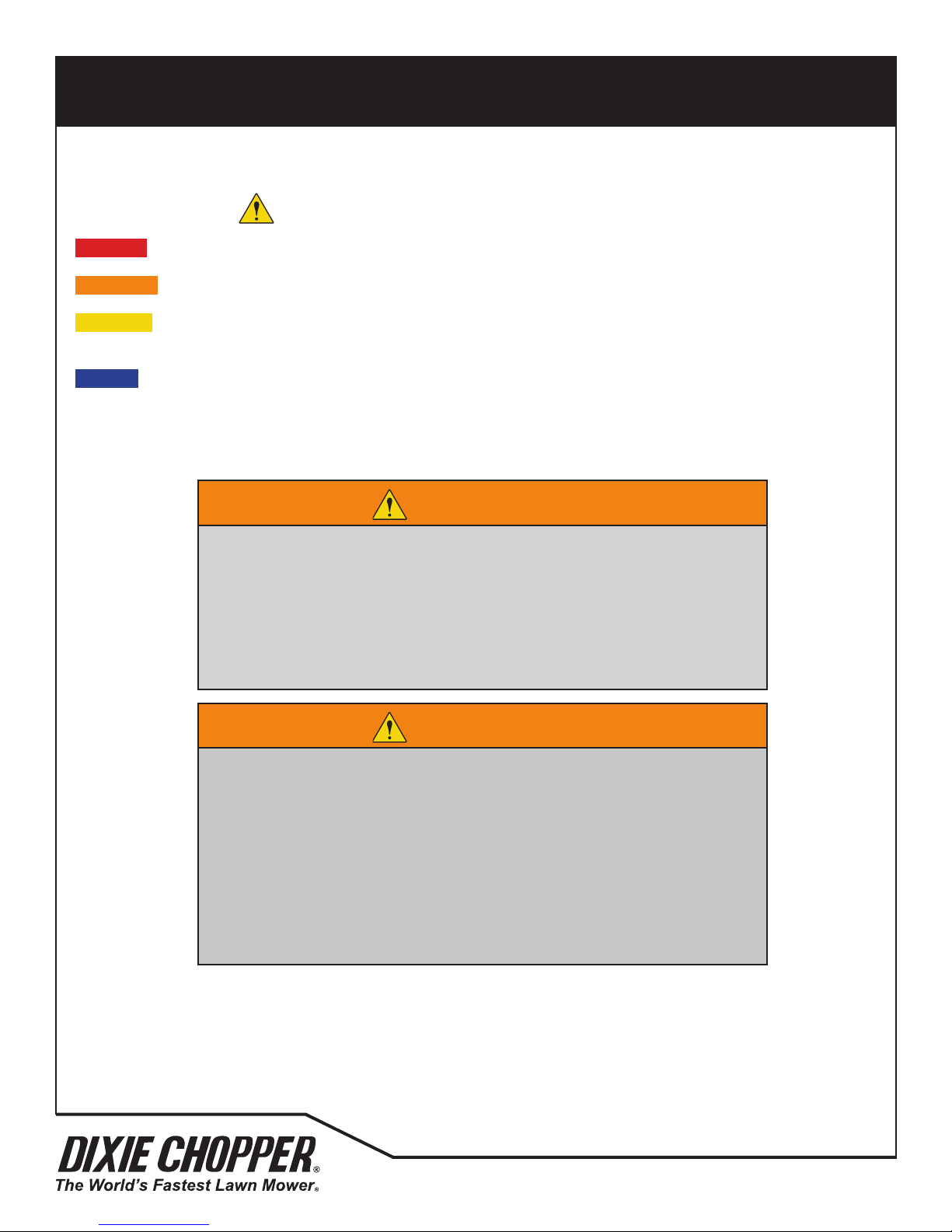
DANGER - Indicates a dangerous condition that WILL cause death or injury unless it is prevented.
WARNING - Indicates a dangerous condition that CAN cause death or injury unless it is prevented.
CAUTION - Indicates a dangerous condition that can cause injury and property damage unless it is prevented. The label
can indicate work procedures that are not safe.
NOTICE - Indicates a condition that can cause damage to the property unless it is prevented. The label can indicate
work procedures that are not safe.
Some illustrations in this manual show the shields, guards or plates, removed. Do not operate this equipment without
these devices correctly fastened in position.
3
This safety alert symbol gives a warning of possible hazards.
WARNING
The OPC System on this mower prevents the operation of the mower unless
a.) The PTO switch is in the OFF position and b.) The drive control levers are in the
Neutral position.
The system will stop the engine if the operator leaves the operator position without:
a.) The drive control levers in of the Neutral position
b.) the PTO switch in the OFF position.
NEVER operate the mower unless the OPC System operates correctly.
WARNING
1. Before you leave the operator position, for any reason:
– Return the drive control levers to Neutral.
– Disengage all drives.
– Engage the parking brake.
– Stop the engine and remove the ignition key.
2. Keep your hands, feet and clothing away from moving parts. Wait for all
movement to stop before you clean, adjust or service the mower.
3. Keep persons and animals away from the area of operation.
4. Never carry passengers.
5. Never operate the equipment without a correctly fastened grass deector in
position.
If additional information or service is needed, contact your Authorized Dixie Chopper Dealer. Your Dealer knows the
current methods to service this equipment.
6
700493
Page 9

SPECIFICATIONS
4.1 ENGINE SPECIFICATIONS
Make Briggs & Stratton
Model V-Twin Professional Series
Type Four cycle, air cooled, Gasoline
Number of Cylinders 2
Bore and Stroke 2.97 in. (8.38 cm) x 2.89 in. (7.34 cm)
Total Displacement 40.03 in3 (0.656 l)
Intake System Naturally Aspirated
Gross Intermittent Power 18 hp (13.4 kW) @ 3600 RPM
Compression Ratio 8.5:1
Maximum Speed 3650 ± 100 rpm (No Load)
Low Idle 1750 ± 100 rpm (No Load)
Rotation Clockwise viewed at ywheel
Fuel System 2 Barrel Float Feed Carburetor
Fuel 87 Octane Gasoline
Injection System Magnetron
Spark Plug Gap 0.030 Inch (0.76 mm)
Engine Oil (API Class) SF, SG, SH, SJ or higher
Oil Pan Capacity 2 quarts (1.89 l)
Starter 12 Volt Electric Start
Alternator 12 Volt, 16 Amp
Dry Weight 84 lb. (41.3 kg)
Dimensions
(Length x Width x Height)
Emission Regulation
4
Pursuit 1832S / 1836S / 1836D / 1844D
®
Maximum 10% Ethanol
19.1 x 18.2 x 14.3 in.
(50.65 x 47.07 x 58.14 cm)
700493
7
Page 10

SPECIFICATIONS
4.2 DIMENSIONS AND WEIGHTS
1832S 1836S 1836D 1844D
A - Width of Cut 32 inch 36 inch 44 inch
B - Maximum Width 41.25 inch 44.75 inch 53.5 inch
C - Height 40 inch 44 inch
D - Total length 68.5 inch 63.5 inch 65 inch 67 inch
E - Wheel Base 37.4 inch 31.75 inch 33.5 inch 35.75 inch
F - Front Wheel Track 21.6 inch 24.25 inch 28.75 inch
G - Rear Wheel Track 27.25 inch 27.75 inch 26.5 inch
Weight of unit 339 lb. 344 lb. 409 lb. 445 lb.
Rear Wheel Tire Size 16 x 6.5-8 16 x 7.5-8
Rear Wheel Type Turf
Real Wheel Tire Pressure 8-10 psi
Front Wheel Tire Size 9 x 3.5-4
Front Wheel Type Smooth
Front Wheel Tire Pressure 12-15 psi
4
1832S 1836S 1836D 1844D
8
700493
Page 11

SPECIFICATIONS
SPECIFICATIONS 4
SPECIFICATIONS 4
D
E
D
C
SPECIFICATIONS 4
E
D
D
E
D
C
C
1832S
4
C
F
G
A
B
E
D
1836S
C
F
G
A
B
E
D
1836D
C
F
G
A
B
1844D
F
G
A
B
700493
E
C
E
9
Page 12
SPECIFICATIONS
4.3 MOWER SPECIFICATION
Battery: 12V, 300 CCA
Service Brake: Dynamic braking through the traction circuit
Parking Brake: Integrated in transmission
Fuel Tank: 5 U.S. Gallons (18.9 l)
Traction Drive: Pursuit 1332S / 1836S - Belt driven single hydrostatic drive
Cutting Unit Drive: Belt drive
Ground Speed: Pursuit 1832S / 1836S: 0-6 mph
Reverse Speed: Pursuit 1832S /1836S: 0-6.5 mph
Pursuit 1832S Cutting Performance: Up to 1.8 acres/hr. @ 6 mph
Pursuit 1836S Cutting Performance: Up to 2.18 acres/hr. @ 6 mph
Pursuit 1836D Cutting Performance: Up to 2.54 acres/hr. @ 7 mph
Pursuit 1844D Cutting Performance: Up to 3.1 acres/hr. @ 7 mph
4
Pursuit 1836D / 1844D - Belt driven dual hydrostatic Hydro-Gear® EZT.
Pursuit 1836D / 1844D: 0-6 mph
Pursuit 1836D / 1844D: 0-3 mph
4.4 CUTTING UNIT SPECIFICATION
1832S 1836S / 1836D 1844D
Blade Length 16.25 inch 13.75 inch (34.9 cm) 15.125 inch (38.4 cm)
Number of blades 2 3
Height of cut adjustment
Blade Tip Speed
@ 3600 rpm engine speed
4.5 BELT SPECIFICATION
Pursuit 1832S / 1836S Traction Belt: 4L-Section, Wrapped, Belt
Pursuit 1836D / Pursuit 1844D Traction Belt: 4L-Section, Wrapped Belt
Pursuit 1832S Engine to Deck Belt: 5L-Section, Wrapped Belt
Pursuit 1836S Engine to Deck Belt: 5L-Section, Wrapped Belt
Pursuit 1836D Engine to Deck Belt: 5L-Section, Wrapped Belt
Pursuit 1844D Engine to Deck Belt: 5L-Section Wrapped Belt
Pursuit 1836S / Pursuit 1836D Deck Belt: HA-Section, Wrapped Belt
Pursuit 1844D Deck Belt: HA-Section Wrapped Belt
327 feet/second 315 feet/second 310 feet/second
Six 1/2 inch spacers placed above or below the front wheel mount
and three position rear deck plate.
10
700493
Page 13
SPECIFICATIONS
4.6 RECOMMENDED LUBRICANTS
Engine Oil:
API Classication grades SF, SG, SH, SJ or higher
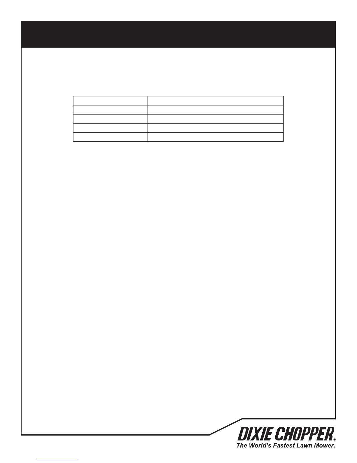
Temperature Viscosity
Above 100° F (38° C) SAE 30 or Synthetic SAE 5W-30
40° to 100° F (4° to 38° C) SAE 30 or SAE 10W-30 or Synthetic SAE 5W-30
0° to 40° F (-18° to 4° C) SAE 5W-30 or SAE 10W-30 or Synthetic SAE 5W-30
Below 0° F (-18° C) SAE 5W-30 or Synthetic SAE 5W-30
Drive Axle Fluid:
The drive axle uid is SAE 20W50 API Classication SL.
Grease:
NLGI Grade 2-EP Lithium Complex Grease containing Molybdenum Disulde.
4.7 SLOPES
DO NOT USE ON SLOPES GREATER THAN 15°. The 15° slope was calculated with static stability measurements according
to the requirements of BS EN ISO 5395-3.
4
4.8 ACCESSORIES
4.8.1 STRIPING KIT
Product number TBD
4.8.2 MULCHING KIT
Kit Number TBD
4.8.3 ACCELERATOR BAGGER
Kit Number TBD
4.9 SUPPORT LITERATURE
Contact your Dixie Chopper Dealer for a complete listing of literature available for your mower.
Operator’s Manual: 700465
Mower Parts Manual: 700484
Service & Repair Manual: TBD
700493
11
Page 14
DECALS
800XXX
General Safety Decal - Pursuit/Havoc
PN: 800XXX
NOTES:
1.25” x 9”
800866
800920
CHOKE
LOW-CUTHIGH-CUT
800775
MEDIUM-CUT
800800
Neutral Release - Pursuit
PN: 800800
NOTES:
13.98” x .83”
30229
30229
Notes:
4.5” x 2”
30229
800848
Notes:
4.5” x 2”
DO NOT OPERATE WITHOUT OPERATOR CONTROLLED
DISCHARGE CHUTE (OCDC), DISCHARGE DEFLECTOR,
ENTIRE GRASS COLLECTION SYSTEM, OR MULCHING
KIT IN PLACE. DO NOT REMOVE GRASS CATCHER
UNTIL BLADES HAVE STOPPED.
5
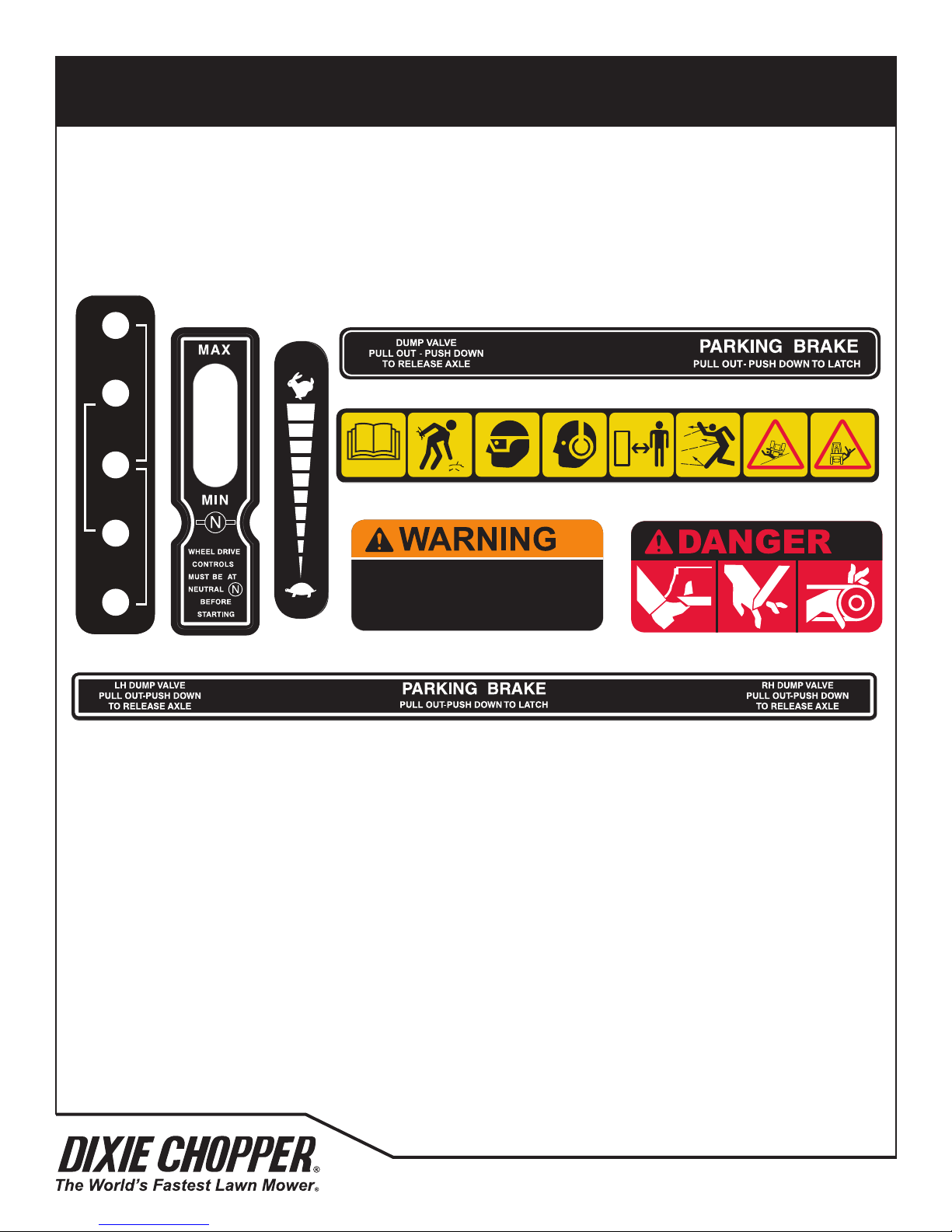
5.1 SAFETY & INSTRUCTION DECALS
Understand the purpose of these decals. The decals are important to the safe operation of the
mower. REPLACE THE DAMAGED DECALS IMMEDIATELY.
*Dual-drive
models only
*Dual-drive models only
*Single-drive models only
12
700493
Page 15

CONTROLS
6
6.1 MOWER CONTROLS
1832S / 1836S
6.8.3
836D and WZT 1844D
1836D / 1844D
6.9.4
6.9.1
6.4
HR
6.3
6.2
STOP
6.5
6.8.1
6.8.2
6.6
6.4
HR
6.3
6.7
6.5
6.2
STOP
6.9.2
6.6
700493
6.9.2
6.9.3
6.9.5
6.6
6.7
13
Page 16
CONTROLS
CONTROLS 6
1/2
FUEL
6.2.5
6.2.7
6.2.7
6.2.8
6.2.9
6.2.10
CONTROLS 6
STOP
RUN
START
Normal Operation
Position
Neutral Release
Position
WZT 1836D/1844D
WZT 1836S
Engaged
Disengaged
Neutral Release
6
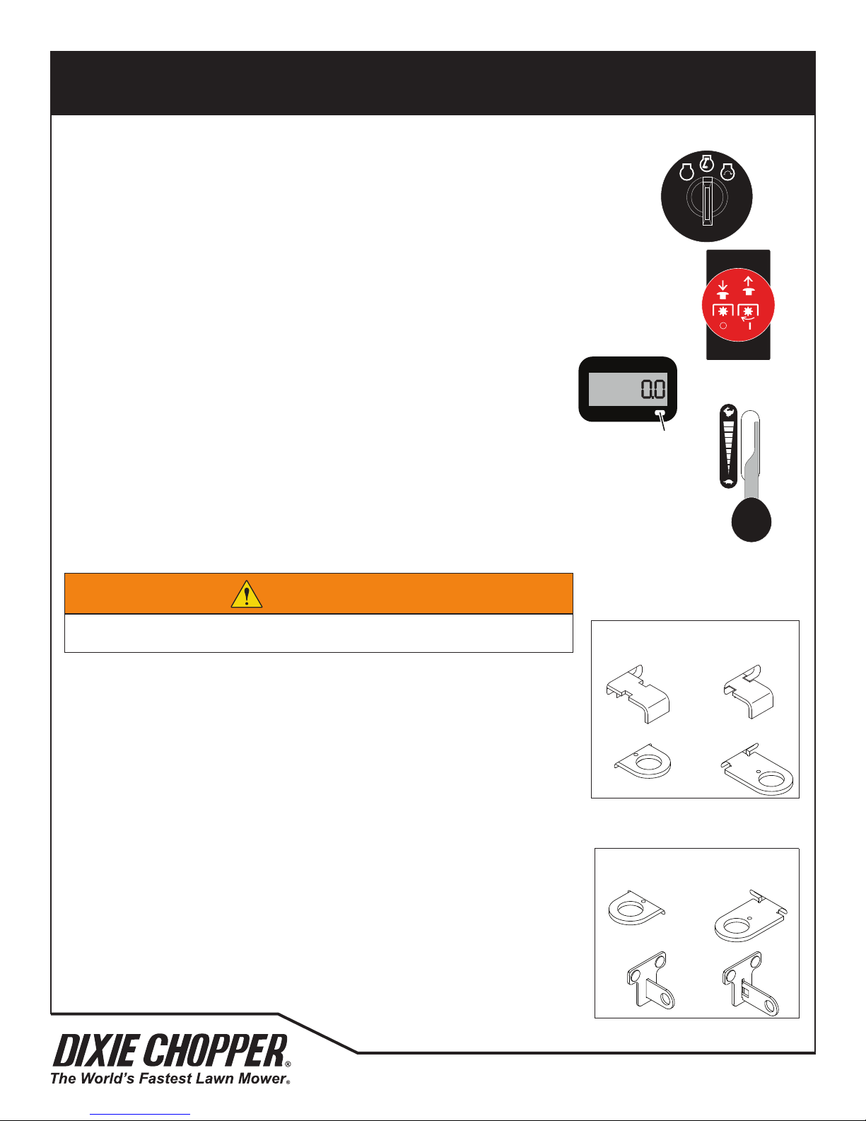
6.2 IGNITION SWITCH
The ignition switch has three positions, OFF, RUN and START.
OFF
STOP
6.3 PTO SWITCH
The PTO switch is a 2-position knob type switch to engage and to disengage the cutting unit.
The PTO switch must be in the OFF (down) position to start the engine.
Pull on the red knob to move the switch to the ON position. When the PTO switch is in the ON position,
the cutting unit is engaged.
Always mow with the throttle lever in the fast position.
6.4 HOUR METER
The hour meter shows the hours of operation, voltmeter and engine speed.
HR
Press and release the mode button to toggle between functions.
6.5 THROTTLE LEVER
The throttle lever controls the engine speed. Always operate the mower at full
Mode
Button
throttle during normal operation.
6.6 NEUTRAL RELEASE
The 1832S / 1836S mower has one neutral release lever to move the mower without the engine
running. The 1836D/1844D mower has two neutral release levers to move the mower without the
engine running.
RUN
START
WARNING
The mower wheels will turn with the neutral release lever in the release position and the parking brake
disengaged. Do not move the neutral release lever to the released position with the mower on a slope.
1832S/1836S Mowers: Push the neutral release lever in to the released position and
lower into the slot. Lift up and pull the neutral release lever toward you to return the
mower to normal operation.
1836D/1844D Mowers: Pull the neutral release lever toward you to the released
position and lower into the slot. Lift the neutral release lever and the lever spring will
return the lever to normal operation.
6.7 PARKING BRAKE
The parking brake lever is used to prevent movement of the mower.
The 1832S/1836S mower has one parking brake lever on the right side of the mower.
The 1836D/1844D mower has one parking brake lever in the center of the mower.
To engage the parking brake, pull the parking brake lever to the engaged position and
lower into the slot. Lift up and push the parking brake lever to the disengaged position
to disengage the parking brake.
Normal Operation
Position
WZT 1836S
WZT 1836D/1844D
Position
WZT 1836S
WZT 1836D/1844D
Position
Position
14
700493
Page 17
CONTROLS
CONTROLS 6
.1
6.
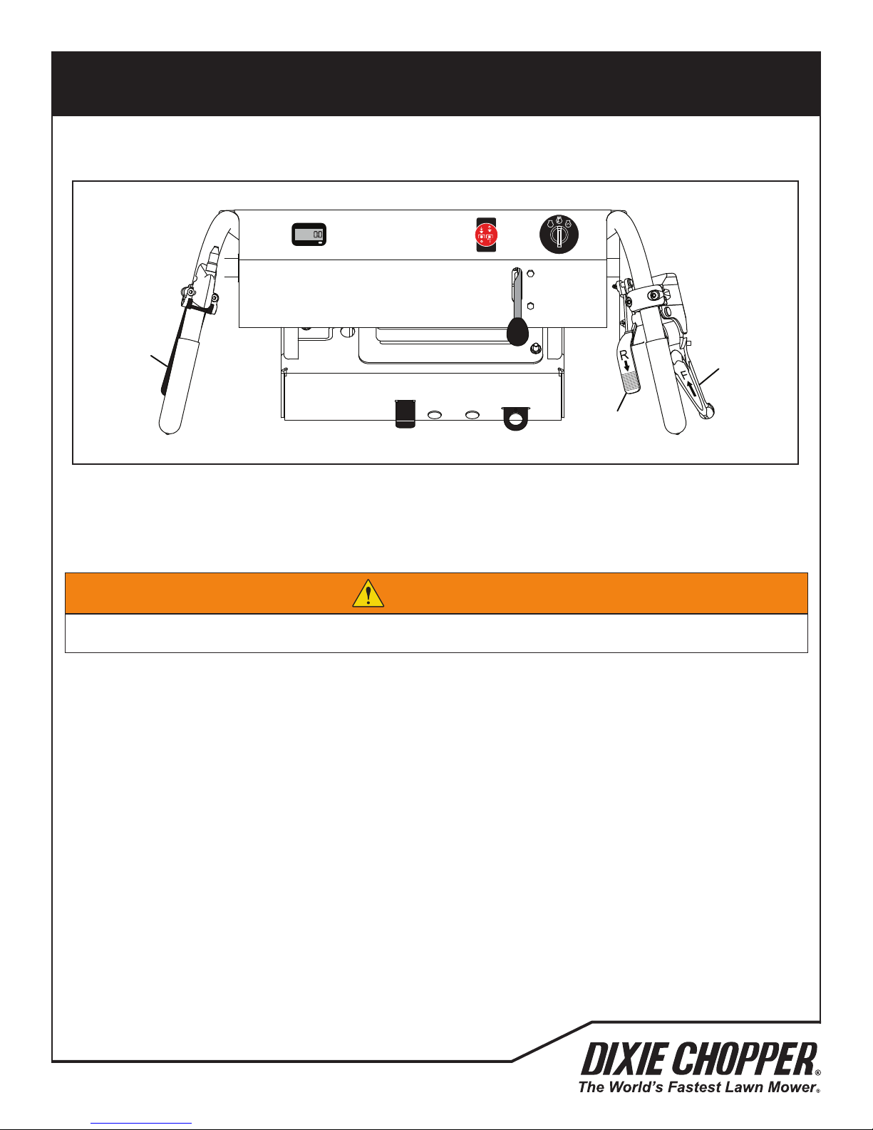
6.8 1832S / 1836S CONTROLS
6
HR
8.3
6.8.1 FORWARD CONTROL LEVER
Slowly move the forward control lever toward the handle to drive the mower in the forward direction. The closer the
lever is moved toward the handle, the faster the mower will move. When the lever is released, the lever will return to the
neutral position.
STOP
6.8
6.8.2
WARNING
To prevent injury or loss of control, always adjust the mower speed to a comfortable walking speed.
Make sure of your footing keep a tight grip on the handles and walk. Never run when you operate the mower.
The forward control lever must be in the neutral position to start the mower.
6.8.2 REVERSE CONTROL LEVER
Press the reverse control lever to drive the mower in the reverse direction. The more the lever is pressed, the faster the
mower will move. When the lever is released, the lever will return to the neutral position.
The reverse control lever must be in the neutral position to start the mower.
6.8.3 OPC LEVER
The OPC lever is used to prevent mower operation without an operator at the controls. Press the lever against the handle
to allow operation of the drive controls and cutting unit.
If the OPC lever is released with the cutting unit engaged and/or the control levers out of the Neutral position, the engine
will stop. Do not operate the equipment with the OPC System disconnected or the system does not operate correctly.
700493
15
Page 18
6.9.1
6.9.2
3
CONTROLS
6
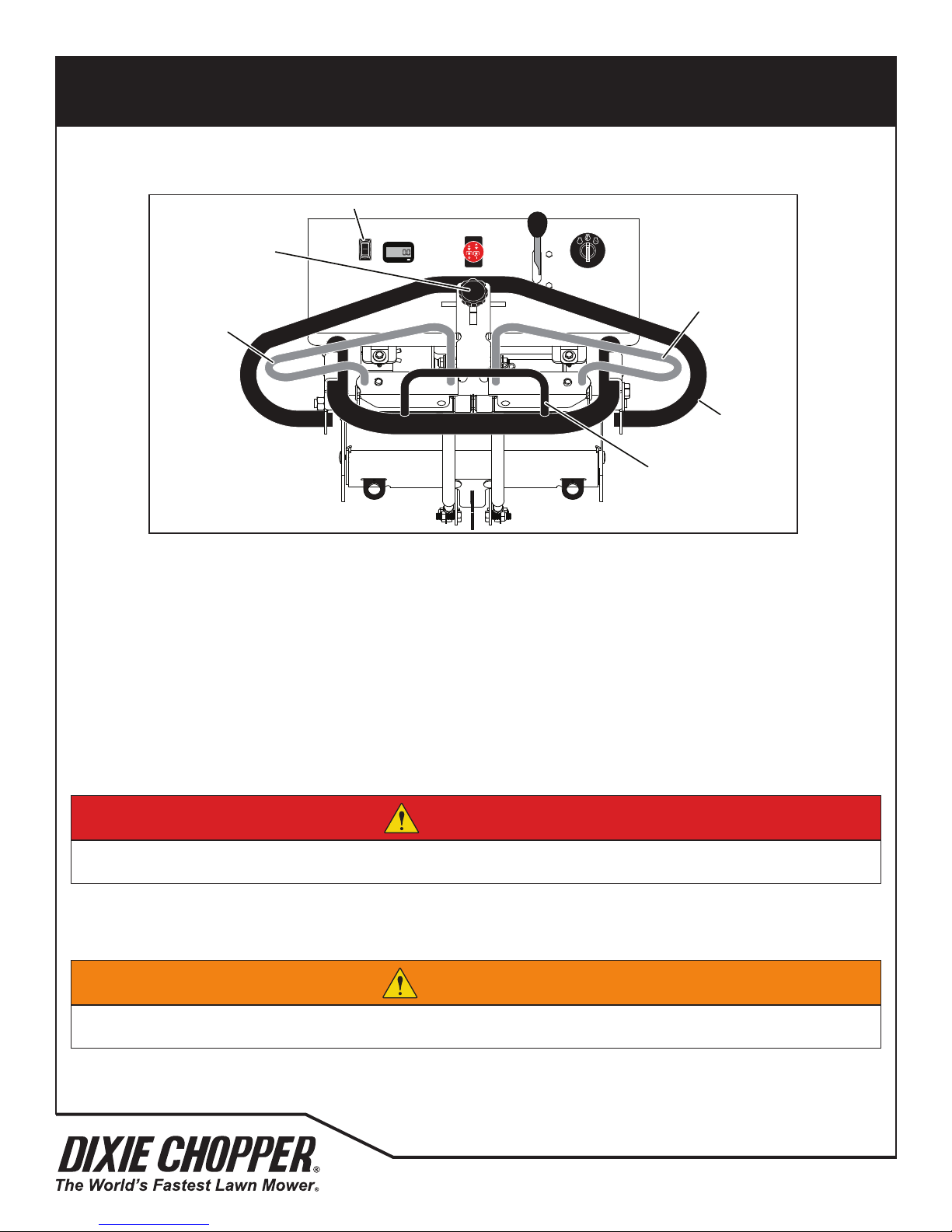
6.9 1836D / 1844D CONTROLS
6.9.4
HR
STOP
6.9.2
6.9.
6.9.5
6.9.1 LIGHT SWITCH
The light switch controls the operation of the mower work lights. Never operate the work lights with the engine stopped.
Press the front of the light switch to turn on the lights. Press the rear of the light switch to turn off the lights.
6.9.2 STEERING CONTROL LEVERS
The mower has a separate drive axle for each rear wheel. The right-side control lever controls the operation of the rightside wheel motor. The left-side control lever controls the operation of the left-side wheel motor. When the steering control
levers are released, the levers will return to the Neutral position. See 7.8 for the operation of the steering control levers.
The steering control levers must be in the Neutral position and the parking brake engaged to start the mower.
6.9.3 FORWARD STEERING LEVER STOP
The forward steering lever stops limits the forward speed.
DANGER
To prevent personal injury or death, do not quickly move the steering control levers or suddenly start and stop the
mower. You must use more caution when you turn the mower or when you operate on slopes.
6.9.4 MOW SPEED ADJUST KNOB
The mow speed stop is used to limit the mow speed to less than the full forward speed of the mower. Loosen the knob
and adjust the mower speed to a comfortable walking speed. Tighten the knob.
WARNING
To prevent injury or loss of control, always adjust the mower speed to a comfortable walking speed.
Make sure of your footing keep a tight grip on the handles and walk. Never run when you operate the mower.
6.9.5 REVERSE STEERING LEVER STOP
The reverse steering lever stop limits the reverse speed.
16
700493
Page 19
OPERATION
7.1 DAILY INSPECTION
7
CAUTION
The inspection must be done each day when the engine is turned off and all uids are cold. Engage the parking
brake, stop the engine and remove the ignition key
• Do a visual inspection of the mower. Look for indications of wear or loose hardware. Look for any components that
are not included on the mower or damaged components. Check for fuel and oil leaks to make sure the connections
are tight. Make sure that all hoses are in good condition.
• Check the fuel supply and crankcase oil level. When the engine is cold, all uids must be at the full level mark.
• Check the engine oil cooler ns for dirt or grass. Clean with compressed air as required before you operate the
mower.
• Check all tires for the correct pressure.
• Test the OPC system.
700493
17
Page 20
OPERATION
7.2 Pursuit 1832S / 1836S OPC SYSTEM
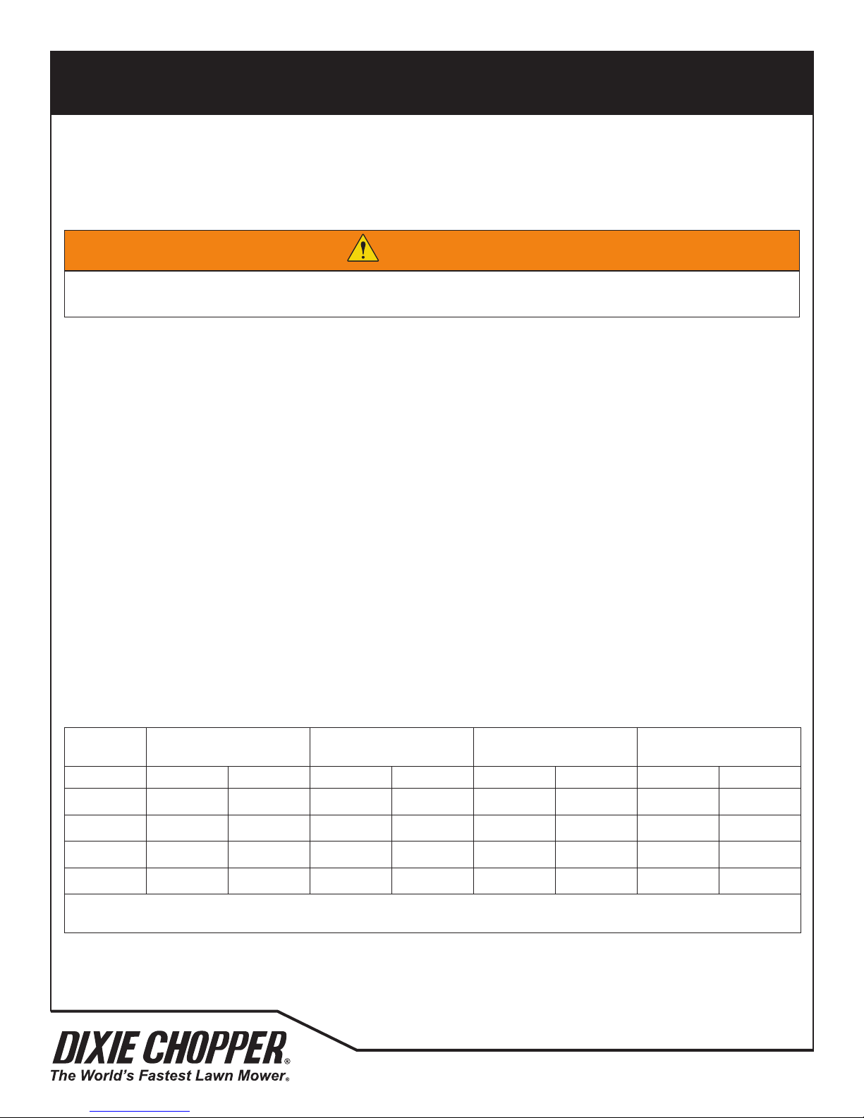
The 1832S / 1836S OPC System prevents the engine to start unless the forward and reverse levers are in the Neutral
position and the PTO switch is in the OFF (Down) position. The system stops the engine if the OPC lever is released with
7
WARNING
Do not operate the equipment with the OPC System disconnected or the system does not operate correctly.
Do not disconnect or prevent the operation of any switch.
the PTO switch in the ON position or the forward and reverse levers out of the NEUTRAL position.
Do each of these tests to make sure the Interlock System operates correctly. If any of the tests fail, stop the test and have
the system inspected and repaired as shown below:
• The engine does not start during test 1
• The engine does start during tests 2 and 3
• The engine continues to run during test 4
Refer to the chart below for each test and follow the check () marks across the chart. Turn off the engine between each
test.
TEST 1: The test shows the normal engine start procedure. The operator is behind the mower, OPC lever is closed, the
forward and reverse levers are in the NEUTRAL position and the PTO switch is in the OFF (down) position. The engine will
start.
TEST 2: The engine must not start if the PTO switch is in the ON position.
TEST 3: The engine must not start if the forward or reverse lever(s) is out of the NEUTRAL position.
TEST 4: Start the engine with the normal procedure. Turn on the PTO switch and release the OPC lever. The engine must
stop. The cutting unit blades must not rotate after seven (7) seconds.
Test OPC Lever Closed PTO Switch OFF
Yes No Yes No Yes No Yes No
1
2
3
4
Start the engine with the normal procedure, move position of the switch and release the OPC lever.
The engine must stop immediately and the cutting unit blades must not rotate after seven (7) seconds.
ü ü ü ü
ü ü ü ü ü
ü ü ü
ü
*
ü
*
Forward and Reverse
Levers in Neutral
ü
Engine Starts
*
18
700493
Page 21
OPERATION
7.3 Pursuit 1836D / 1844D OPC SYSTEM
The 1836D/1844D OPC System prevents the engine to start unless the steering control levers are in the Neutral position
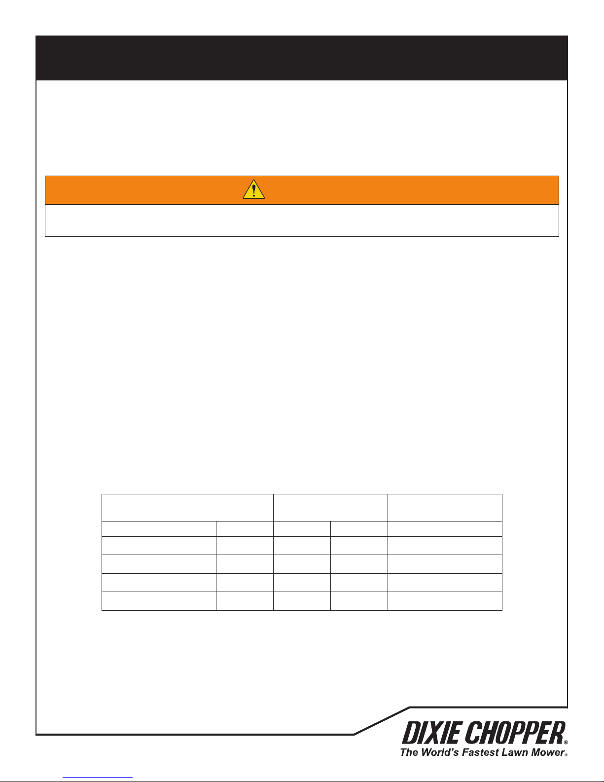
and the PTO switch is in the OFF (Down) position. The cutting unit does not operate with the drive levers in the Neutral
position.
7
WARNING
Do not operate the equipment with the OPC System disconnected or the system does not operate correctly.
Do not disconnect or prevent the operation of any switch.
Do each of these tests to make sure the Interlock System operates correctly. If any of the tests fail, stop the test and have
the system inspected and repaired as shown below:
• The engine does not start during test 1
• The engine does start during tests 2 and 3
• The engine continues to run during test 4
Refer to the chart below for each test and follow the check (ü) marks across the chart. Turn off the engine between each
test.
TEST 1: The test shows the normal engine start procedure. The operator is behind the mower, the steering control levers
are in the NEUTRAL position and the PTO switch is in the OFF (down) position. The engine will start.
TEST 2: The engine must not start if the PTO switch is in the ON position.
TEST 3: The engine must not start if the steering control lever is out of the NEUTRAL position. Repeat test for both the left
and right side steering control levers.
TEST 4: Start the engine with the normal procedure. Make sure the steering control levers are in the Neutral position.
Turn on the PTO switch. The cutting unit blades must not rotate.
Test PTO Switch OFF
Yes No Yes No Yes No
1
2
3
4
ü ü ü
ü ü ü
ü ü ü
ü
*
Steering Control
Levers in Neutral
ü
Engine Starts
*
700493
19
Page 22
OPERATION
7.4 OPERATING PROCEDURE
7
CAUTION
To prevent injury, always wear safety glasses, leather work shoes or boots, and ear protection.
1. Always start the engine with the operator behind the mower, never while next to the mower. Never start the engine
with persons near the mower.
2. Never operate the engine without enough ventilation or in an enclosed area. The carbon monoxide in the exhaust
fumes can increase to dangerous levels.
3. Keep your hands and feet away from moving parts and the cutting units. When possible, do not adjust the mower
with the engine started.
4. Do not operate the mower with loose or damaged components. All components must be correctly fastened to the
mower. Mow when the grass is dry to get the best results.
5. First cut in a test area so that you completely understand the operation of the mower and controls.
6. Inspect the area to nd the safest procedure for the mower. Check the height of the grass, the type of terrain and the
conditions of the surface. Each condition needs the correct adjustments and precautions.
7. Do not release the cut grass in the direction of persons or allow persons near the mower while in operation. The
owner and operator are responsible for injuries caused to persons near the mower and any damage to their property.
CAUTION
Remove all objects you can nd before you operate the mower. Carefully enter a new area and always operate at
speeds that allow you to control the mower safely.
8. Be careful when you operate near to gravel areas (roads, parking areas, cart paths). Stones released from the
equipment can cause injuries to persons and cause damage to the equipment.
9. When you are not mowing grass, always turn off the PTO switch.
10. Before you move across or operate on the paths or roads, turn off the PTO switch, lift the cutting unit and travel at
decreased speed. Look for trafc.
11. When you hit an object or mower starts to cause vibration that is not normal, inspect the mower for damage and
make repairs.
WARNING
Before you clean, adjust or repair this equipment, always turn off the PTO switch, lower the cutting unit to the
ground, engage the parking brake, stop the engine and remove the ignition key.
12. Travel at decreased speed and be careful when you operate on the slopes or near sharp edges.
13. When you operate in the reverse direction, look behind you and down to make sure the path is clear. Use caution
when you go near corners, trees or other objects that can prevent a clear view.
14. Never use your hands to clean the blades. Use a brush to remove the grass clippings from the blades. The blades are
sharp and can cause injuries.
20
700493
Page 23
OPERATION
PTO
7
7.5 STARTING THE ENGINE
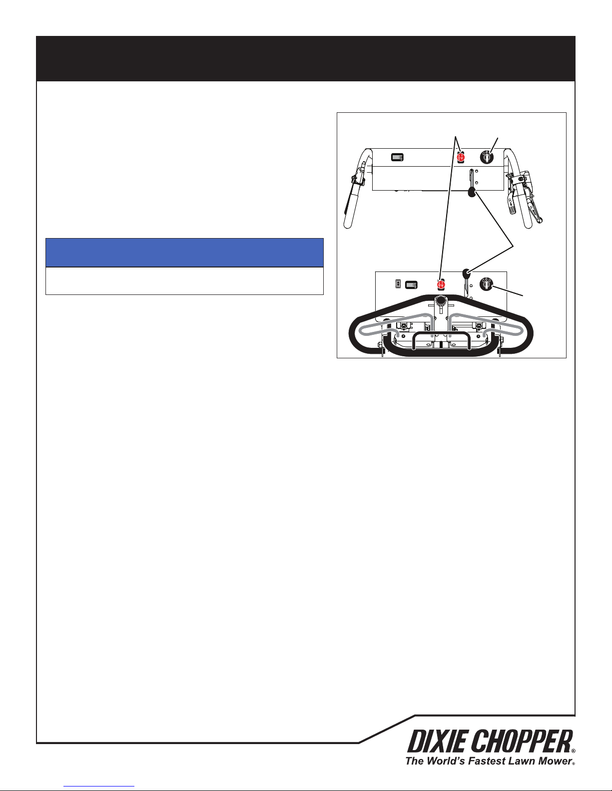
Start the engine with the operator behind the mower, the PTO
switch in the OFF position and the parking brake engaged.
Remove your hands from the drive control levers.
Set the throttle lever to half throttle.
Turn the ignition switch to the RUN position. The hour meter will
show the engine operation hours.
NOTICE
Do not hold the ignition switch in the START position for
more than 10 seconds.
Turn the ignition switch to the START position. Release the key
when the engine starts. Allow 30 seconds between start tries to
allow the starter motor to become cool.
Allow the engine to become warm before you operate the engine
at full throttle.
WZT 1836S
HR
WZT 1836D/1844D
HR
Switch
Ignition
Switch
STOP
Throttle
Lever
STOP
Ignition
Switch
7.6 TO STOP THE ENGINE
To stop and park the mower in normal conditions:
1. Turn the PTO switch to the OFF position. Drive the mower to a at and level area to park the mower.
2. Remove your hands from the drive control levers.
3. Engage the parking brake.
4. Turn the ignition switch to the OFF position and remove the key before you leave the mower.
If an emergency occurs and you must park the mower in the area of operation, follow the guidelines set by the grounds
manager. If the mower is parked on a slope, chock or block the wheels.
700493
21
Page 24
OPERATION
OPERATION 7
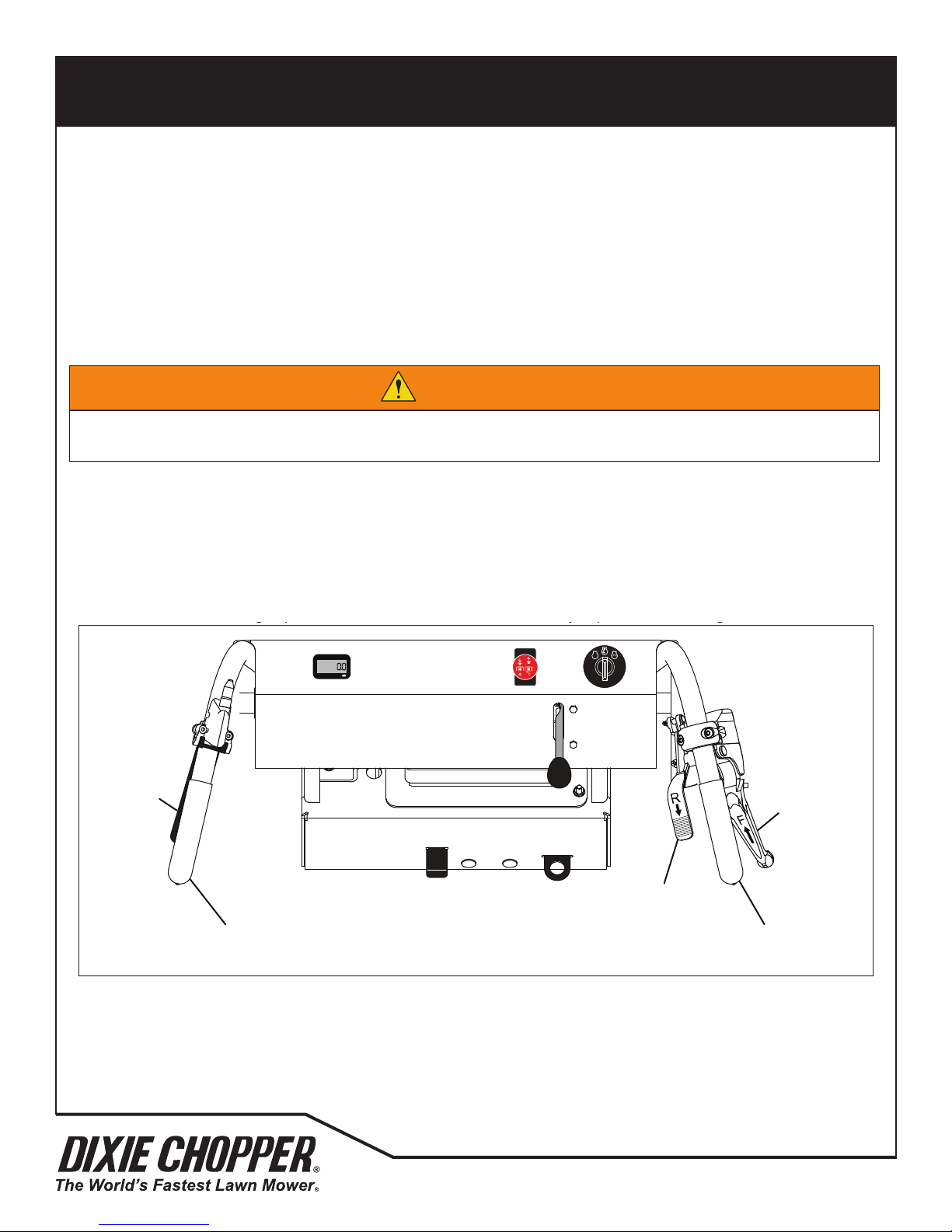
7.7 WZT 1836S DRIVING _______________________________________________________
Read and follow all safety instructions contained in this manual when you operate the mower. When you operate in the
reverse direction, look behind you to make sure you have a clear path. Do not mow in reverse.
If the OPC lever is released with the cutting unit engaged and/or the control levers out of the Neutral position, the
engine will stop. Do not operate the equipment with the OPC System disconnected or the system does not operate
correctly.
Slowly move the forward lever toward the handle to drive the mower forward. The closer the lever is to the handle, the
more the forward speed is increased.
Slowly move the forward lever toward the handle to drive the mower forward. The closer the lever is to the handle, the
more the forward speed is increased.
To turn the mower to the left, push forward on the right side handle while you pull back on the left side handle.
To turn the mower to the right, push forward on the left side handle while you pull back on the right side handle.
WARNING
To prevent injury or loss of control, always adjust the mower speed to a comfortable walking speed.
Make sure of your footing keep a tight grip on the handles and walk. Never run when you operate the mower.
!
7.7 Pursuit 1832 /1836S DRIVING
Read and follow all safety instructions contained in this manual when you operate the mower. When you operate in the
reverse direction, look behind you to make sure you have a clear path. Do not mow in reverse.
If the OPC lever is released with the cutting unit engaged and/or the control levers out of the Neutral position, the engine
will stop. Do not operate the equipment with the OPC System disconnected or the system does not operate correctly.
Slowly move the forward lever toward the handle to drive the mower forward. The closer the lever is to the handle, the
more the forward speed is increased.
7
WARNING
To prevent injury or loss of control, always adjust the mower speed to a comfortable walking speed.
Make sure of your footing keep a tight grip on the handles and walk. Never run when you operate the mower.
Slowly move the forward lever toward the handle to drive the mower forward. The closer the lever is to the handle, the
more the forward speed is increased.
To turn the mower to the left, push forward on the right side handle while you pull back on the left side handle.
To turn the mower to the right, push forward on the left side handle while you pull back on the right side handle.
HR
STOP
OPC
Lever
Forward
Control
Lever
Reverse Control
Lever
Left
Handle
22
Right
Handle
700493
Page 25
OPERATION
7 OPERATION
7.8 WZT 1836D/1844D DRIVING _________________________________________________
Read and follow all safety instructions contained in this manual when you operate the mower. When you operate in the
reverse direction, look behind you to make sure you have a clear path. Do not mow in reverse.
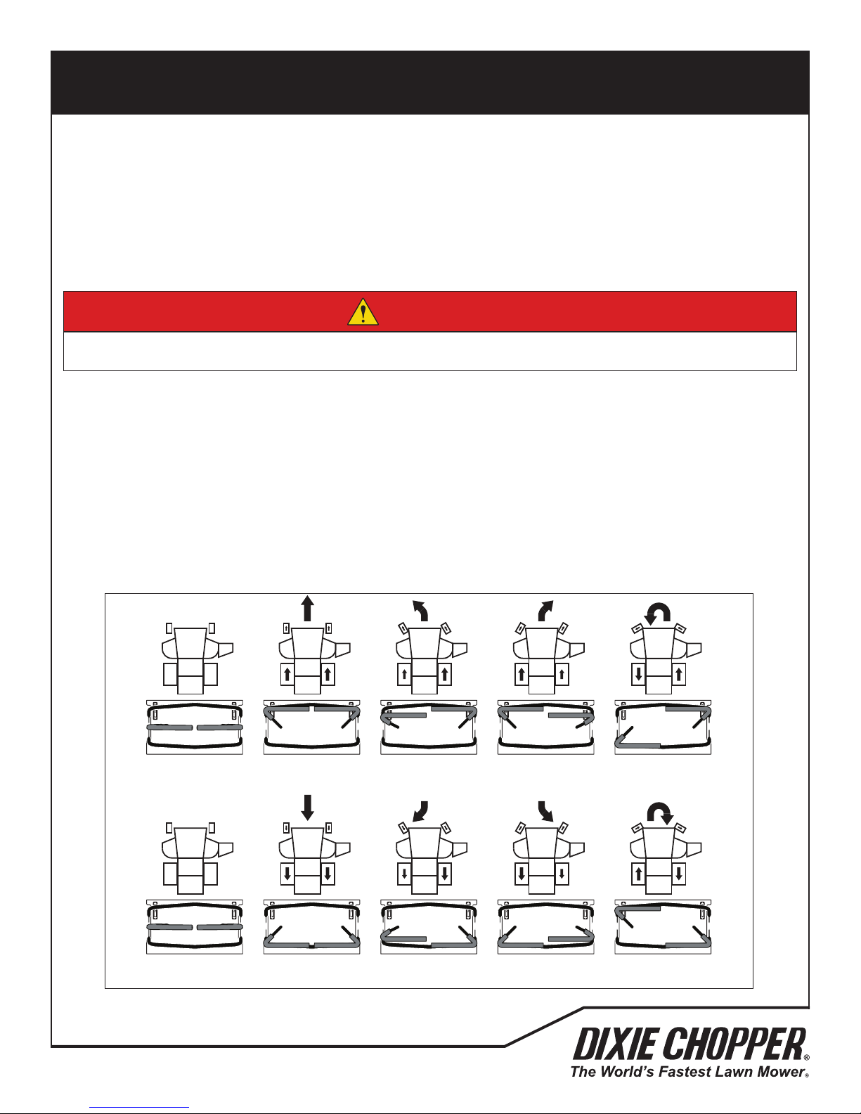
Slowly and equally push both the right-side and left-side control levers toward the forward stop to drive the mower in the
forward direction. The more the levers are pressed the more the forward speed is increased. Press the levers against
the forward stop for the maximum forward speed.
Slowly and equally pull both the right-side and left-side control levers toward the reverse stop to drive the mower in the
reverse direction. The more the levers are pulled the more the reverse speed is increased. Press the levers against the
reverse stop for the maximum reverse speed.
To turn the mower to the left, push the right-side drive lever more than the left-side drive lever. The greater the
difference in lever position, the sharper the mower will turn. To do a zero radius left turn, press the right-side lever
toward the forward stop and pull the left-side lever toward the reverse stop.
To turn the mower to the right, push the left-side drive lever more than the right-side drive lever. The greater the
difference in lever position, the sharper the mower will turn. To do a zero radius right turn, press the left-side lever
toward the forward stop and pull the right-side lever toward the reverse stop.
DANGER
To prevent personal injury or death, do not quickly move the steering control levers or suddenly start and stop the
mower. You must use more caution when you turn the mower or when you operate on slopes.
!
7.8 Pursuit 1836D/1844D DRIVING
Read and follow all safety instructions contained in this manual when you operate the mower. When you operate in the
reverse direction, look behind you to make sure you have a clear path. Do not mow in reverse.
Slowly and equally push both the right-side and left-side control levers toward the forward stop to drive the mower in the
forward direction. The more the levers are pressed the more the forward speed is increased. Press the levers against the
forward stop for the maximum forward speed.
7
DANGER
To prevent personal injury or death, do not quickly move the steering control levers or suddenly start and stop the
mower. You must use more caution when you turn the mower or when you operate on slopes.
Slowly and equally pull both the right-side and left-side control levers toward the reverse stop to drive the mower in the
reverse direction. The more the levers are pulled the more the reverse speed is increased. Press the levers against the
reverse stop for the maximum reverse speed.
To turn the mower to the left, push the right-side drive lever more than the left-side drive lever. The greater the difference
in lever position, the sharper the mower will turn. To do a zero radius left turn, press the right-side lever toward the
forward stop and pull the left-side lever toward the reverse stop.
To turn the mower to the right, push the left-side drive lever more than the right-side drive lever. The greater the
difference in lever position, the sharper the mower will turn. To do a zero radius right turn, press the left-side lever toward
the forward stop and pull the right-side lever toward the reverse stop.
N N N N N NN N N N
Neutral Forward Forward Left
N N N N N N N N N N
Neutral Reverse Reverse Left
700493
Tur n
Tu r n
23
Forward Right
Tu r n
Reverse Right
Tu r n
Zero Radius
Left Turn
Zero Radius
Right Turn
Page 26
15° Maximum
15° Maximum
15° Maximum
OPERATION
7
WARNING
To prevent injuries, when the blades rotate, keep your hands, feet and clothing away from the cutting unit.
NEVER use your hands to clean the cutting unit. Use a brush to remove grass from the blades. The blades can be
sharp and can cause injury.
DO NOT operate the cutting unit without the discharge deector installed.
7.9 MOWING
To mow:
1. Put the PTO switch in the ON position.
2. Push the drive control levers to drive the mower forward. The
blades will start turning. Never mow in the reverse direction.
3. Slow down when you turn the mower or mow on slopes.
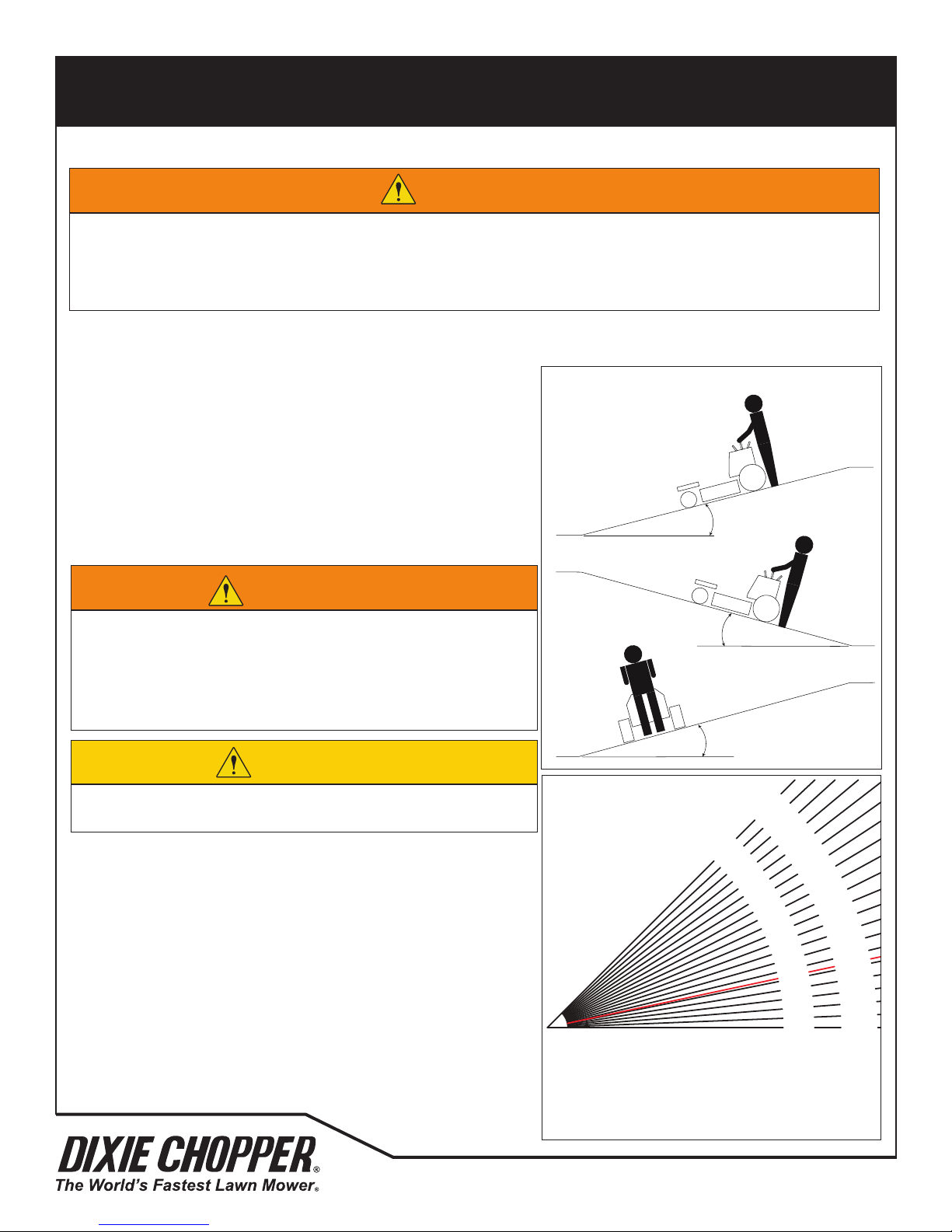
7.10 MOWING ON SLOPES
The mower is made to have good traction and to have good balance.
Operate the mower with caution when you drive on a slope. If you
drive on wet grass, the traction and steering control of the mower is
decreased.
15° Maximum
WARNING
To make sure that the mower does not turn over, the safest method
to drive on a slope is to operate on a slop horizontally. Travel at a
slow speed and do not make turns that are not necessary.
Check for hazards on the road that are not visible to the drivers.
Keep the cutting unit lowered when you operate on the slopes.
CAUTION
Do not operate the mower on the slopes greater than 15° or a
26.8% slope.
1. Always cut the grass with the engine at full throttle. Control
the forward speed with the steering control levers to keep the
correct performance.
2. If the mower moves to the side or the tires damage the turf,
drive the mower on a slope with a decreased angle.
3. If the mower continues to move to the side and damage the
turf, the slope is at an angle that is not safe. Do not continue
to drive toward the top of the slope. Carefully drive toward
the bottom of the slope.
4. When you drive toward the bottom of a slope with a high
angle, lower the cutting unit to the ground. This procedure
makes sure the mower does not turn upside down.
5. Correct tire pressure is necessary for maximum traction.
Front - 12-15 psi - Rear - 8-10 psi
15° Maximum
15° Maximum
Degrees
45°
43-1/2°
85%
80%
75%
70%
65%
60%
55%
50%
45%
40%
42°
40-1/4°
38-3/4°
36-3/4°
35%
30%
25%
20%
15%
10%
5%
0%
35°
33°
28-3/4°
31°
26-1/2°
24-1/4°
21-3/4°
Grade
100%
95%
90%
General slope of roadway embankment - 45°
Steepest Grass Area - 31°
Slope of the average roof - 19-1/4°
2nd Class highway maximum grade 4-1/2°
Toll road or freeway - 1-3/4°
19-1/4°
16-3/4°
14°
11-1/4°
8-1/2°
5-3/4°
2-3/4°
0°
24
700493
Page 27
OPERATION
7.11 TOWING THE MOWER
If the mower has a problem and the engine will not run, move the Neutral release lever to the Neutral position and load
the mower on a trailer. If a trailer is not available, tow the mower at a slow speed for short distances.
Be careful when you load or unload the mower on the trailer. Fasten the mower to the trailer to prevent the mower to
move on the trailer. Engage the parking brake.
If the trailer is moved on the highway, inate the tires to the maximum pressure recorded on the tire before you fasten the
mower to the trailer. Decrease the tire pressure after the mower is removed from the trailer.
Disengage the parking brake.
Before towing, disengage the parking brake.
7
NOTICE
When you tow the mower, do not drive more than 2 mph (3.2 km/hr). Jacobsen recommends that you do not tow
the mower for long distances.
When the mower gets to the service area, move the neutral release lever to the normal operation position and engage the
parking brake.
700493
25
Page 28
MAINTENANCE AND LUBRICATION CHARTS
8.1 MAINTENANCE CHART
Mower Service Interval Chart
Interval Item Section
• Replace engine oil
First 5 Hours
Each day (10 Hours)
Each three days (25 Hours) • Clean air lter element and pre-cleaner See 9.4
Each week (50 Hours)
Each Two weeks (100 Hours)
Each month (250 Hours) • Check electrical wiring See 9.14
Each two months (400 Hours) • Replace fuel lter
Yearly
• Replace engine oil lter
• Check electrical wiring
• Lubricate spindles and casters
• Check Safety OPC System
• Check engine oil level
• Clean area around mufer and controls
• Clean engine rotating screen
• Check fuel lines and ttings
• Inspect parking brake and steering control lever linkage
• Inspect deck and drive belts
• Check for loose components
• Lubricate grease ttings
• Check engine exhaust system
• Replace engine oil and lter
• Replace air lter and pre-cleaner
• Replace spark plugs
• Clean engine cooling system
• Check engine valve clearance (Briggs & Stratton Dealer)
See 9.3
See 9.3
See 9.14
See 8.2
See 7.2
See 9.3
See 9.5
See 8.2
See 9.8
See 9.3
See 9.4
8
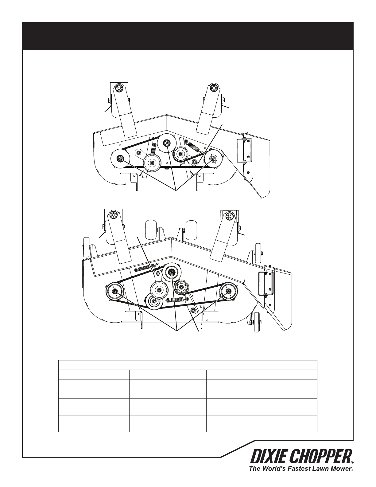
Grease Fittings
1. Deck Spindle (3)
2. Belt Idler Pivot (1 (1832S/1836S/1836D) or 2 (1844D))
3. Front Wheel Bearing (2)
26
700493
Page 29
MAINTENANCE AND LUBRICATION CHARTS
8 MAINTENANCE AND LUBRICATION CHARTS
8.2 LUBRICATION CHART _____________________________________________________
8.2 LUBRICATION CHART
8
3
1
3
2
2
3
3
8.3 FLUID REQUIREMENTS
Engine Oil with Filter 2 quarts (1.89 l) SAE 10W-30 API Classication SJ
1836S Drive Axle 2.07 quarts (1.96 l) SAE 20W-50 API Classication SL
1836D / 1844D
Drive Axle
Fuel 5 U.S. Gallons (18.9 l)
700493
12
Fluid Requirements
Quantity Type
1.75 quarts (21.66 liter)
Each (2 Per Mower)
SAE 20W-50 API Classication SL
27
87 Octane Gasoline
Maximum 10% Ethanol
Page 30

MAINTENANCE
9.1 GENERAL PRECAUTIONS
9
WARNING
Before you clean, adjust or repair this equipment, push PTO switch to the OFF position, lower the cutting unit, engage
the parking brake, stop the engine and remove the key.
Make sure the mower is parked on a solid and level surface. Never work on a mower that is lifted only by the jack.
Always use the jack stands.
A qualied technician must always do adjustments and maintenance. If the correct adjustments can not be made, contact
your Jacobsen Dealer.
Inspect the equipment according to the maintenance schedule and keep complete records.
A. Keep the equipment clean.
B. Keep all moving parts correctly adjusted and lubricated.
C. Replace worn or damaged parts before you operate the mower.
D. Keep all uids at the correct level.
E. Keep the shields in position and all hardware tight.
F. Keep the tires correctly inated.
When you make the adjustments or repairs, do not wear jewelry or loose tting clothing.
Refer to the illustrations in the Parts Manual for the removal and assembly of parts.
When you discard hazardous materials (batteries, lubricants, fuel, anti-freeze), follow your local, state or federal
recommended procedures.
9.2 ENGINE
IMPORTANT - The mower includes a separate Engine Manual prepared by the engine manufacturer. Read the Engine
Manual and know the operation and maintenance of the engine. When you follow the engine manufacturer instructions,
you will make sure of the maximum service life of the engine. The replacement engine manuals are available from the
engine manufacturer.
The operation and maintenance during the rst 5 hours of a new engine can make a difference to the performance and
life of the engine.
During the rst 5 hours of operation, Jacobsen recommends the following.
• Allow the engine to reach a temperature of at least 140° F (60° C) before operation at full load.
• Check the engine oil level two times each day. Higher than normal oil use can occur during the rst 5 hours.
• Change the engine oil and oil lter after the rst 5 hours of operation.
• Refer to the Engine manual for specied maintenance intervals.
NOTICE
The mower operates and cuts correctly at the preset governor setting. Do not change the engine governor setting or
over speed the engine.
28
700493
Page 31
MAINTENANCE
ADD FULL
Dipstick
Level Indicator
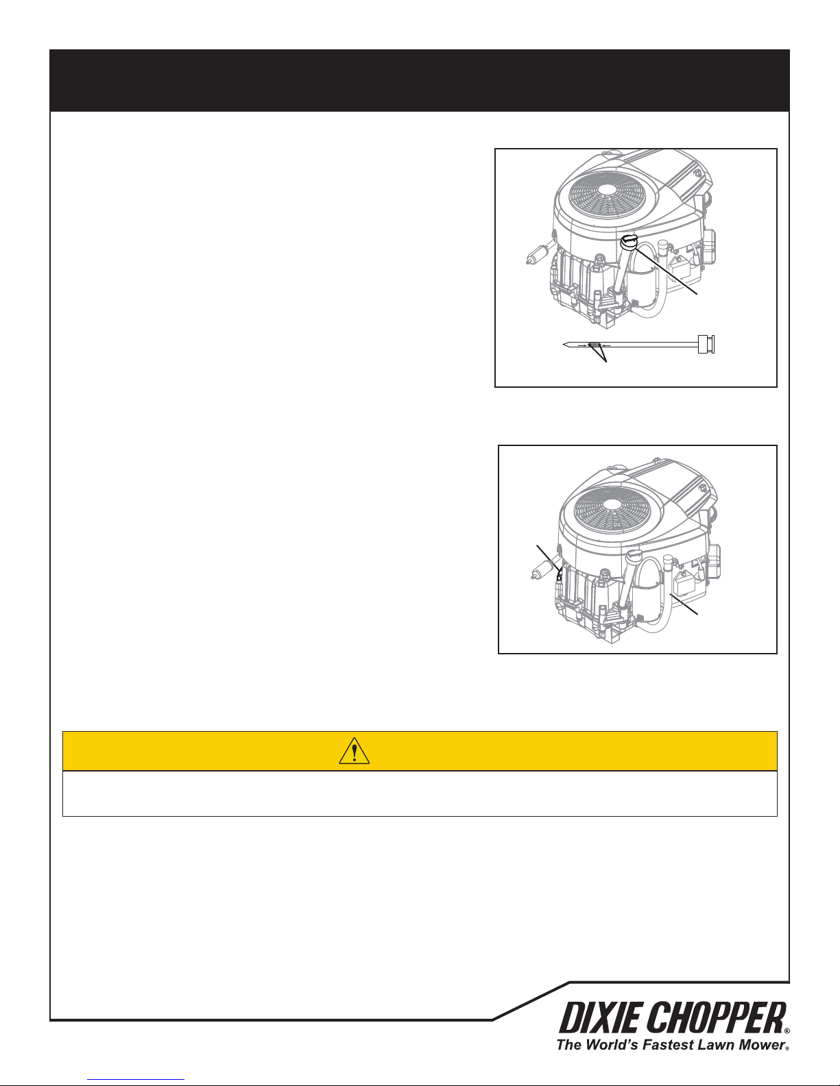
9.3 ENGINE OIL
Check Engine Oil Level
Check the engine oil level before you start the engine or at least ve
minutes after you stop the engine.
A. Park the mower on a level surface.
B. The dipstick is found at the right rear corner of the engine.
Remove the dipstick. Clean the dipstick with a cloth and replace
in position.
C. Remove the dipstick and check the oil level. The oil level must be
between the two level indicators on the dipstick.
Change Engine Oil and Filter
A. Start the engine to increase the temperature, then stop the
engine.
B. Disconnect the oil drain hose from the side of the engine.
Remove the oil drain cap.
C. Lower the drain hose and drain the engine oil into a container.
D. Remove the oil lter.
E. Let the engine oil ow into a container.
F. Clean the lter area on the engine.
G. Apply a thin layer of oil to the gasket on new lter.
Install the oil lter.
H. Tighten the lter until the gasket contacts the oil lter adapter,
then tighten an additional 1/2 to 3/4 turn. Only use your hand
to tighten the lter.
I. Replace the oil drain cap and ll the engine with the correct
quantity and grade of oil through the ller.
J. Start the engine and check around the oil lter gasket for leaks.
K. Stop the engine and check the engine oil level.
9
Dipstick
ADD FULL
Level Indicator
Filter
Drain Hose
The engine oil can damage your skin. Use gloves when you use engine oil. If engine oil touches your skin, clean the
area immediately. Discard used engine oil as shown in local regulations.
700493
CAUTION
29
Page 32
MAINTENANCE
MAINTENANCE 9
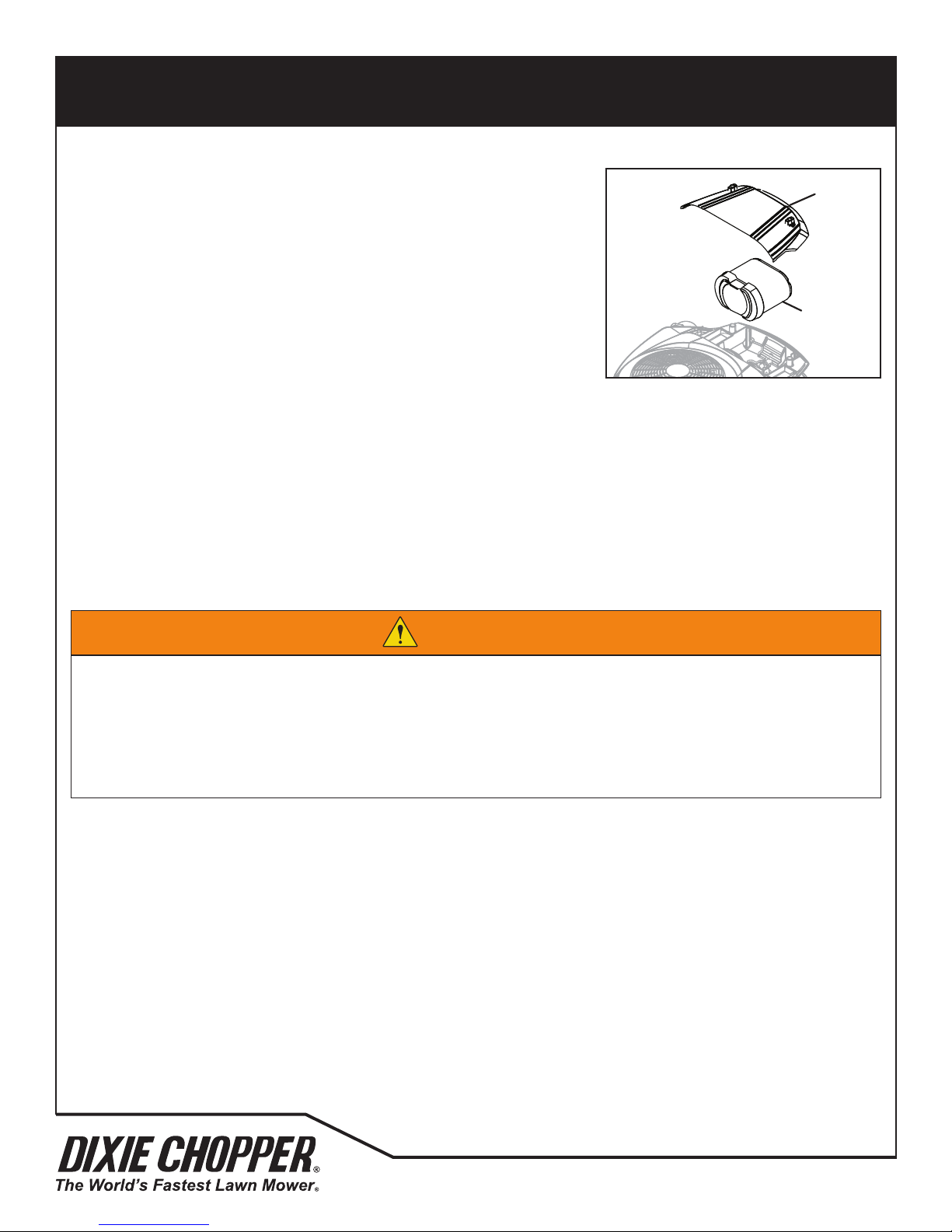
9.4 ENGINE AIR FILTER
Do not remove the element to inspect or clean. Removal of the lter that is not
necessary increases the risk of dust and other particles to enter the engine.
Clean or air lter element every 50 hours. Replace the air lter element each
year.
9
Cover
When service is needed, rst clean the outside of the lter cover. Remove the
cover and the lter element. Make sure dust and other particles do not get into
the engine inlet.
Gently tap the lter on a hard surface to loosen debris. If the lter is excessively
dirty, replace the element. Do not use a damaged element and never use an incorrect element.
Assemble the air lter element and press down until the lter snaps into place. Make sure the element seat correctly.
Assemble the cover to the engine housing. Fasten the cap with the two thumb screws.
9.5 FUEL
Gasoline is ammable. Use caution when you add the fuel to the mower. Only use an approved container. The
spout on the container must t inside the fuel ller neck. Never use the containers that are not approved to keep or
transfer fuel.
Filter
Element
WARNING
Refuel the mower before you start the engine. When the engine is in operation or while the engine is hot, never
remove the fuel cap or add fuel to the mower. Refuel outdoors only and do not smoke when you add fuel.
If the fuel spills, do not try to start the engine, but move the mower away from the area. Until fuel vapors are removed,
do not allow the sparks, open ame or other types of ignition.
Never keep fuel containers near an open ame or any device that can cause the ignition of fuel or fuel vapors.
Always tighten the fuel tank cap and container cap after you add fuel.
Fill the fuel tank to the bottom of the ller neck.
Do not use premium gasoline or an oil-gasoline mixture. Use clean, fresh, regular unleaded gasoline, 85 octane minimum.
When using blended fuel, do not use a blend with more than 10% ethanol. Under no circumstances should you use a
blend with methanol. Refer to the engine’s operator manual for fuel recommendations when using blended fuel.
Check fuel hoses and clamps every 50 hours. Replace fuel hoses and clamps at rst indication of wear or damage.
Keep fuel according to your local, state or federal regulations and instructions from your fuel supplier.
Never allow the tank to become empty.
30
700493
Page 33
MAINTENANCE
9.6 BATTERY
Before you service the battery, make sure the ignition switch is in the OFF position and the key is removed.
9
CAUTION
When you service the battery, always use the tools with insulation, wear protective glasses and protective clothing.
Discard used batteries as shown in your local regulations.
WARNING
The battery contains corrosive acid. Prevent contact with the battery acid.
Always wash your hands after you service a battery.
WARNING
The battery posts, battery terminals and related accessories contain lead and lead compounds, chemicals known to the
State of California to cause cancer and other reproductive harm.
Tighten the battery cables on the battery terminals, To prevent corrosion, apply a layer of silicone dielectric grease to
battery terminals and ends of cables. Keep the vent caps and battery terminal covers in position.
Before you do any welding operation on the mower, always disconnect the battery cables from the battery and the
connectors from the controllers.
Conrm the battery polarity before you connect or you disconnect the battery cables.
When you install the battery, always connect the positive (RED) battery cable before the negative (BLACK) battery cable.
When you remove the battery, always disconnect the negative (BLACK) battery cable before the positive (RED) battery
cable.
Jump-Starting the Mower
A. Before you try to jump-start the mower, check the condition of the drained battery.
B. Connect the positive (+) battery terminal of the charged battery to positive battery terminal of the drained
battery.
C. Connect the negative (–) battery terminal of the charged battery to frame of vehicle with the drained battery.
WARNING
The battery can release hydrogen gas that is explosive. To decrease the risk of an explosion, prevent sparks near the
battery. Always connect the negative jumper cable to the frame of the mower with the drained battery.
D. When the cables are connected, start the engine on the vehicle with the good battery, then start the mower.
700493
31
Page 34
MAINTENANCE
9.7 CHARGE THE BATTERY
9
WARNING
Charge the battery in an area with good airow. The battery can release hydrogen gas that is explosive. To prevent an
explosion, keep any device that can cause sparks or ames away from the battery.
When the battery charger is turned on, to prevent injury, stay away from the battery. A battery that is damaged can
cause an explosion.
Read the battery charger manual for specied instructions on the operation of the charger.
When possible, remove the battery from the mower before you charge the battery. If the battery is not sealed, check and
make sure the level of the electrolyte is above the plates in all of the cells.
Make sure the battery charger is turned OFF, then connect the battery charger to the battery terminals as specied in the
battery charger manual.
Always turn OFF the battery charger before you disconnect the battery charger from the battery terminals.
9.8 ENGINE EXHAUST
WARNING
The exhaust fumes contain carbon monoxide. The carbon monoxide in the exhaust fumes can increase to dangerous
levels. To protect you from carbon monoxide poisoning, inspect the complete exhaust system every month and replace
damaged components immediately.
NEVER operate the engine without enough ventilation.
The temperature of the exhaust components can be greater than 300° F (149° C). To prevent the burns, do not touch a
hot exhaust system.
If you sense a change in the color or sound of the exhaust, stop the engine immediately. Identify the problem and have
the system repaired.
Torque all exhaust manifold hardware equally. Tighten or replace the exhaust clamps.
32
700493
Page 35
MAINTENANCE
9.9 TIRES
Keep the tires correctly inated to increase tire life. Inspect the tread wear.
Check the tire pressure each day, while the tires are cool. Use an accurate low-pressure tire gauge.
Keep the rear tires inated to 8-10 psi. Keep the front tires inated to 12-15 psi.
9
CAUTION
DO NOT try to put a tire on a rim unless you have the correct training, tools and experience. Incorrect mounting can
cause an explosion which can cause injury.
9.10 WHEEL MOUNTING PROCEDURE
WARNING
Make sure the mower is parked on a solid and level surface. Never work on a mower that is supported only by the jack.
Always use jack stands.
If only the front or behind the mower is lifted, put the chocks in front of and behind the wheels that are not lifted.
Remove dirt, grease and oil from the stud threads. Do not lubricate threads.
Put the wheel on the hub. Inspect the wheel to make sure of full contact between surface of wheel and hub.
Tighten all hardware with your ngers, then torque hardware in a criss-cross order. When possible, tighten nuts in the top
position.
Check and torque hardware each day until torque is kept at 65-75 ft-lbs.
700493
33
Page 36
MAINTENANCE
MAINTENANCE 9
9.11 AIR COOLING SYSTEM
The engine on the mower is an air-cooled engine. Dirt and other objects can decrease the air ow and cause the engine
to overheat, cause bad performance and decreased engine life.
9
NOTICE
Do not use water to clean the engine. Water can cause contamination in the fuel system. Use compressed air, a brush
or clean cloth to clean the engine.
Use a brush or a dry cloth to clean the air intake area.
Keep throttle linkage, springs and controls clean.
Use compressed air to remove debris from the engine cooling ns.
Refer to the Engine manual for additional information.
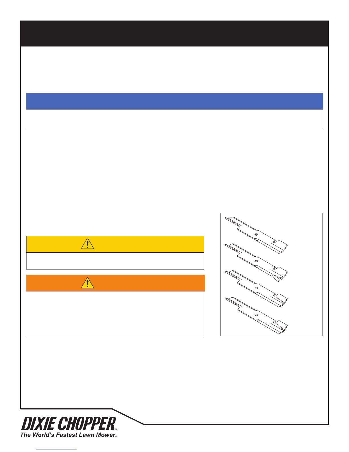
9.12 INSPECTING BLADES
Every 50 hours of operation or when the cutting unit is removed from the
mower, carefully inspect the blades to make sure the blades are in good
condition. Replace any blade that has bends, grooves or cracks.
CAUTION
Be careful when you check blades to prevent pinching hands and
ngers between ends of the blades.
Normal
Blade
Bent
Blade
WARNING
Never try to correct or repair a damaged blade. Always replaced a
damaged blade.
The bends, grooves or cracks can cause a piece of the blade to
become loose and be discharged from the mower. The broken blade
pieces can cause injury to persons or property damage.
A bent blade can have a small crack that can increase and cause a piece of the blade to break. The bent blades can cause
vibration and other stress on the mower.
Grooved
Blade
Cracked
Blade
The dust or sand particles can wear a dangerous groove in the blade between the air vanes and the at part of the blade.
The groove can quickly increase in size and allow a piece of the blade to break.
34
700493
Page 37
MAINTENANCE
9.13 SHARPENING BLADES
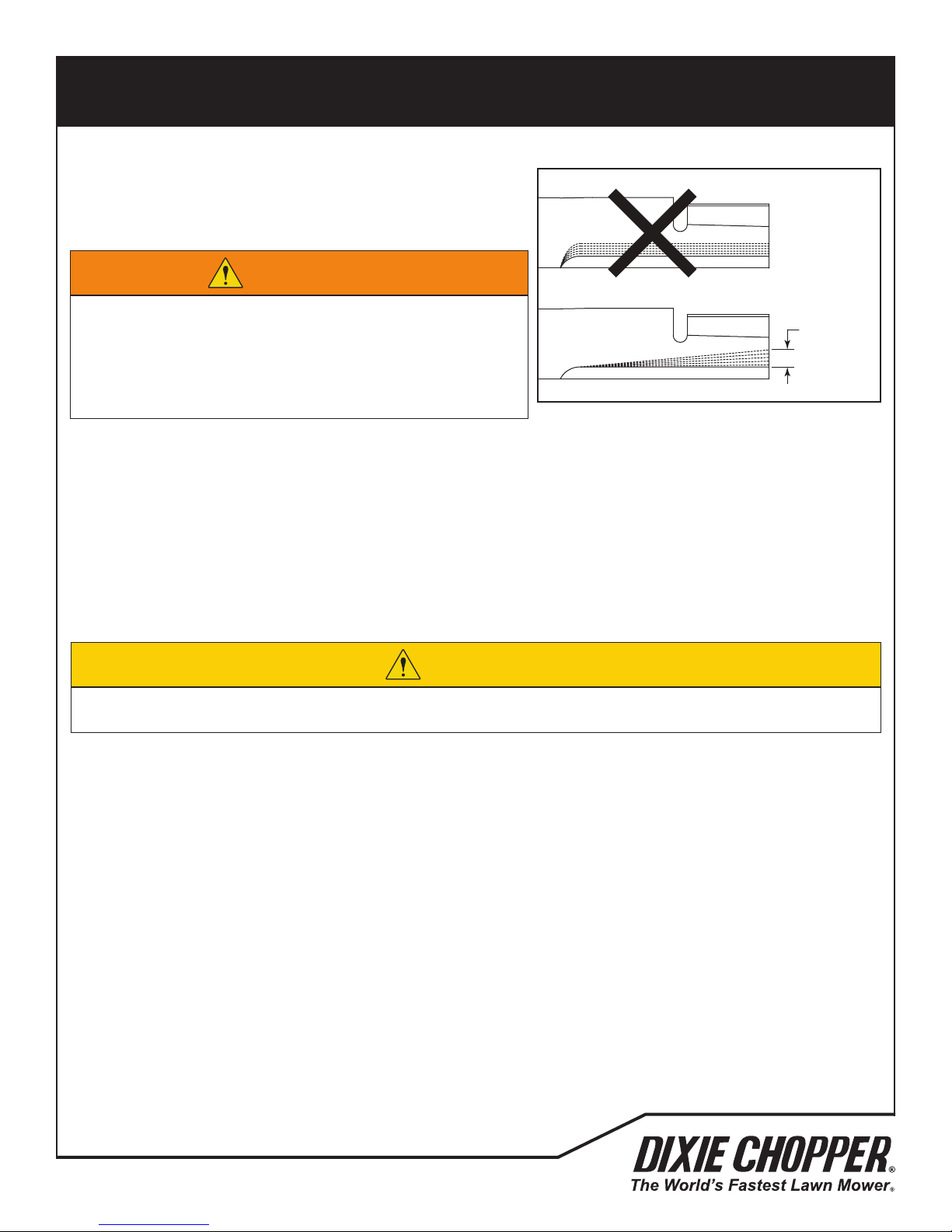
Put a wooden block between the blade and cutting unit housing to
prevent the blade to rotate.
9
WARNING
The cutting unit blades can have sharp edges. To prevent injury,
use caution when you service or hold the blade.
When you remove more than one half inch of material, the blade
tip can break and be discharged from the mower. The broken
blade pieces can cause injury to persons or property damage.
When you prepare or sharpen the blade, do not follow the original grind pattern. Grind new cutting edges at an angle. If
the maximum of 1/2 inch blade loss has occurred, do not sharpen more, replace the blade.
To prevent a blade that is not balanced, make sure an equal amount of material is removed from both ends of the blades.
A blade that is not balanced will cause vibration and can damage the mower. Use a blade balancer to check the blade
after you sharpen.
Torque center blade bolt to 75 to 85 ft-lbs.
9.14 ELECTRICAL SYSTEM
Maximum
1/2 in.
(1.3 cm)
CAUTION
Always turn the ignition switch to the off position and remove the negative (BLACK) battery cable before you inspect
or service the electrical system.
General precautions to decrease electrical problems are:
• Make sure that all the connections are clean and correctly fastened.
• Check the OPC system, fuses and circuit breakers at normal intervals. If the OPC system does not operate
correctly and you can not correct the problem, contact an authorized Jacobsen Dealer.
• Keep the wiring harness away from hot surfaces and moving parts.
• Check the battery and the alternator.
• Do not wash or pressure spray around electrical connections and components.
700493
35
Page 38
MAINTENANCE
9.15 CARE AND CLEANING
Clean the mower and cutting units after each use. To prevent damage to the engine, do not wash the mower with the
engine in operation. When possible, clean the mower with compressed air.
9
NOTICE
Do not wash any part of the mower that is hot. Do not use the high-pressure spray or steam. Use cold water and
automotive cleaners.
Use compressed air to clean the engine and the engine oil cooler ns. Do not pressure wash the engine.
Use clean water to wash your equipment.
NOTICE
To use salt water or drain water is known to cause rust and corrosion of metal parts and can cause damage or failure.
This damage is not included by the factory warranty.
Do not spray water at the control panel, ignition switch or other electrical components.
Clean all plastic or rubber parts with a weak soap solution or use commercially available rubber cleaners.
To keep the original high polish of the berglass parts, wax with a good grade of one-step cleaner wax.
Repair damaged metal surfaces and use Jacobsen touch-up paint. Apply wax to the equipment for maximum paint
protection.
CAUTION
To prevent re, clean grass clippings and dirt from the cutting units, drives, engine and exhaust components.
WARNING
Never use your hands to clean cutting units. Use a brush to remove grass clippings from the blades. The blades are
sharp and can cause injuries.
36
700493
Page 39
MAINTENANCE
9.16 MOWER STORAGE
General
• Clean the mower and lubricate. Repair and paint damaged or open metal.
• Inspect the mower, tighten all hardware, replace worn or damaged components.
• Clean the tires and keep the mower so that the load is not on the tires. If the mower is not on the jack stands,
check tires at normal intervals and add air when needed.
• Keep the mower and all accessories clean, dry and protected from the elements. Never keep the mower near an
open ame or spark which can cause ignition of the fuel or fuel vapors.
Battery
• Remove, clean and keep the battery in the upright position on a surface that is not metal in a cool dry location. To
prevent increased battery discharge, do not keep the battery on a metal surface.
• Check and charge the battery every 60 to 90 days.
• Keep the battery in a cool dry location. To decrease the self discharge rate, the temperature must not be more
than 80° F (27° C) or less than 20° F (-7° C).
Engine
• Change the engine oil and lter.
• Clean the outside surface of the engine. Paint bare metal or apply a thin layer of rust preventative oil.
• Add a fuel stabilizer to prevent the fuel to become stale. See your fuel supplier for instructions. Start the engine.
• Operate the engine for two minutes to circulate the stabilizer throughout the fuel system.
9
Cutting Units
• Completely clean the cutting units. Repair and paint any damaged or bare metal surfaces.
• Lubricate all grease ttings and friction points.
• Apply a thin layer of rust preventative oil to the sharpened edges of the blades.
CAUTION
The cutting unit blades can have sharp edges. To prevent injury, use caution when you service or hold the blade.
After Storage
• Check and install the battery. If necessary, charge the battery.
• Check or service the fuel lter and air cleaner
• Check the level of engine oil and drive axle uid.
• Fill the fuel tank with fuel.
• Make sure the tires are correctly inated.
• Remove all oil from the blades.
• Start the engine at 1/2 throttle. Allow the engine to become warm and lubricated.
WARNING
Never operate the engine without enough ventilation or in an enclosed area. The carbon monoxide in the exhaust
fumes can increase to dangerous levels.
700493
37
Page 40

ADJUSTMENTS
10.1 GENERAL PRECAUTIONS
10
WARNING
Before you clean, adjust or repair this equipment, push PTO switch to the OFF position, lower the cutting unit to the
ground, turn on the parking brake switch, stop the engine and remove the key.
Make sure the mower is parked on a solid and level surface. Never work on a mower that is lifted only by the jack.
Always use the jack stands.
A qualied technician must always do adjustments and maintenance. If the correct adjustments can not be made, contact
your Jacobsen Dealer.
Inspect the equipment according to the maintenance schedule and keep complete records.
A. Keep the equipment clean.
B. Keep all moving parts correctly adjusted and lubricated.
C. Replace worn or damaged parts before you operate the mower.
D. Keep all uids at the correct level.
E. Keep the shields in position and all hardware tight.
F. Keep the tires correctly inated.
When you make the adjustments or repairs, do not wear jewelry or loose tting clothing.
Refer to the illustrations in the Parts Manual for the removal and assembly of parts.
When you discard hazardous materials (batteries, lubricants, fuel, anti-freeze), follow your local, state or federal
recommended procedures.
38
700493
Page 41
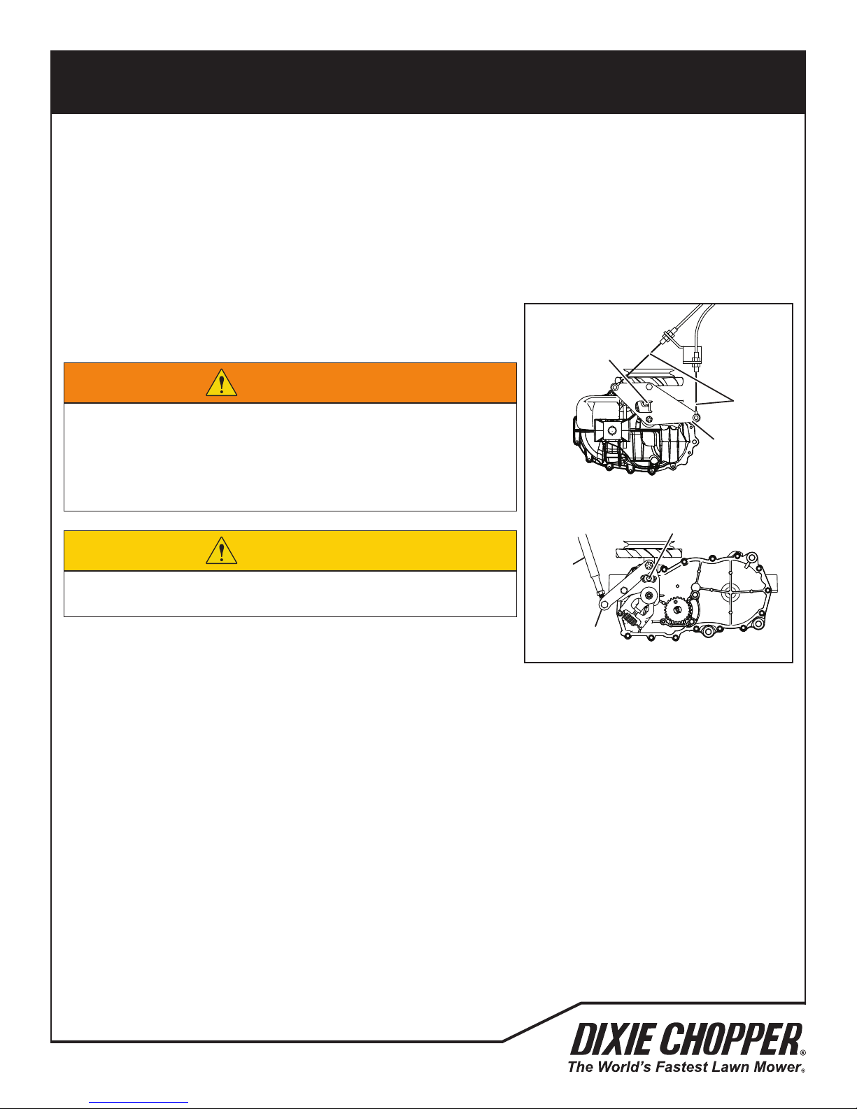
ADJUSTMENTS
10.2 NEUTRAL ADJUSTMENT
The mower must not move with the drive control levers in the Neutral position and the parking brake disengaged.
1832S/1836S: The neutral adjustment is done on the left side of the drive axle.
1836D/1844D: The neutral adjustment must be done separately for the left and right side axles. The adjustment is done
in the space between the two drive axles.
To adjust the neutral position:
1. Lift the mower so the rear wheels are off the ground. Disengage the
control linkage from the control arm.
10
WZT 1836S
1832S/1836S
Neutral
Screw
WARNING
Control
Make sure the mower is parked on a solid and level surface.
Never work on a mower that is supported only by the jack. Always use
jack stands. Put chocks in front of and behind the front wheels.
To prevent injury, do not adjust the neutral setting with the engine
running.
WZT 1836D/1844D
1836D/1844D
Neutral
Screw
Linkage
Control
Arm
CAUTION
When you check the drive axle neutral adjustment, the rear wheels may
turn. To prevent injury, use caution to prevent contact with the wheels.
2. Start the engine, move the throttle lever to the fast position and
disengage the parking brake. Note if the rear wheel rotates and the
direction the wheel rotates. Engage the parking brake and stop the engine. Do not adjust the neutral setting with the
engine running.
a. If the wheel does not rotate, proceed with Step 5.
b. If the wheel does rotate, proceed with Step 3.
3. Loosen the neutral screw and rotate the control arm 5° in the same direction that the wheel turned. Tighten the
neutral screw.
4. Start the engine and check the neutral adjustment. Repeat Step 3 until the wheel does not rotate.
5. 1832S/1836S: Torque the neutral screw to 96 in. lb. (8 ft. lb.). Connect the control linkage to the control arm.
1836D/1844D: Torque the neutral screw to 180 in. lb. (15 ft. lb.). Connect the control linkage to the control arm.
6. Repeat the adjustment procedure on the right side axle.
Control
Linkage
Control
Arm
700493
39
Page 42
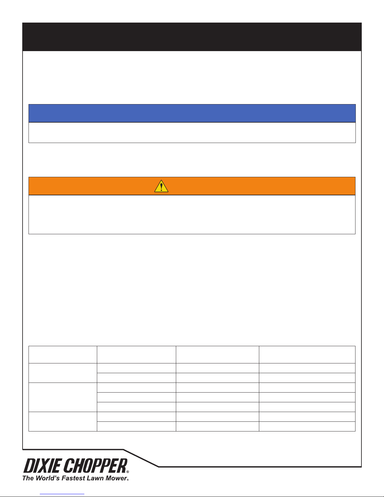
ADJUSTMENTS
10.3 HEIGHT OF CUT
The height of cut for the cutting unit is adjusted from 1-1/2 to 4-1/2 inch (3.8-11.4 cm) in 1/2 inch (1.3 cm) steps. The
height of cut result can be different from the heights given because of the condition of the turf and other conditions.
10
NOTICE
When cutting rough areas, a lower height of cut can cause scalping. Adjust the height of cut to prevent damage to
the turf.
Park the mower on a at and level surface. Engage the parking brake, stop the engine and remove the key. Push down
on both handles to lift the cutting unit off the ground. Put 9 inch (22.7 cm) supports below the cutting unit. Lower the
cutting unit on the 9 inch (22.7 cm) supports.
WARNING
To prevent injury, make sure the cutting unit is on the supports. The supports will prevent the cutting units to lower
accidentally while you adjust the height of cut.
Make sure the parking brake is engaged, stop the engine and remove the key before you make adjustments to the
cutting units.
Refer to the decal on the cutting units or the chart below to set the height of cut.
To change the front wheel height of cut
A. Remove the retaining ring pins and any spacers above the pivot block. Remove the caster wheel yoke from the
pivot block
B. Install the correct number of 1/2 inch (1.3 cm) spacers onto the front wheel yoke.
C. Slide the front wheel yoke into the pivot block. Place the remaining 1/2 inch (1.3 cm) spacers on front wheel yoke
shaft above the pivot block.
D. Assemble the retaining ring pins.
E. Repeat for the other front wheel.
HOC Chart
Height of Cut
Low-Cut
Medium-Cut
High-Cut
1/2 inch (1.3 cm) Spacers
Below Pivot Block
0 6 Top Position Holes
1 5 Top Position Holes
2 4 Middle Position Holes
3 3 Middle Position Holes
4 2 Middle Position Holes
5 1 Bottom Position Holes
6 0 Bottom Position Holes
1/2 inch (1.3 cm) Spacers
Above Pivot Block
Deck Bracket Hardware
Location
40
700493
Page 43
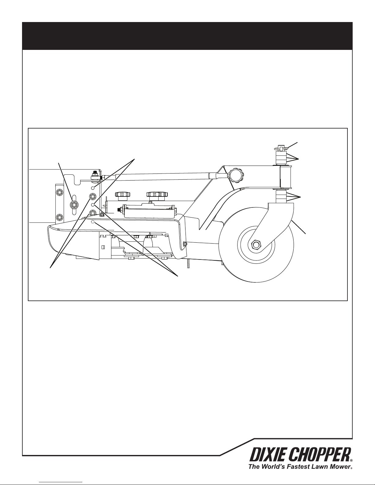
ADJUSTMENTS
hardware.
bracket hardware in the top position. For 2-1/2 to 3-1/2 inch (6.3 to 8.9 cm) height of cut, install the deck bracket
hardware in the middle position. For height of cut from 4 to 4-1/2 inches (10.2 to 11.4 cm) install the deck bracket
hardware in the bottom position.
To change the deck bracket height of cut
A. Support the mower and remove the deck bracket hardware from both sides of the mower. Loosen the slot
hardware.
B. Check the deck bracket mounting position. For height of cut from 1-1/2 to 2 inches (3.8 to 5.1 cm) install the
deck bracket hardware in the top position. For 2-1/2 to 3-1/2 inch (6.3 to 8.9 cm) height of cut, install the deck
bracket hardware in the middle position. For height of cut from 4 to 4-1/2 inches (10.2 to 11.4 cm) install the
deck bracket hardware in the bottom position.
Slot
hardware
10
Top position
Retaining Ring
Pin
Spacers above
pivot block
Spacers below
pivot block
Front wheel
yoke
Deck hardware in
center position
Bottom position
700493
41
Page 44
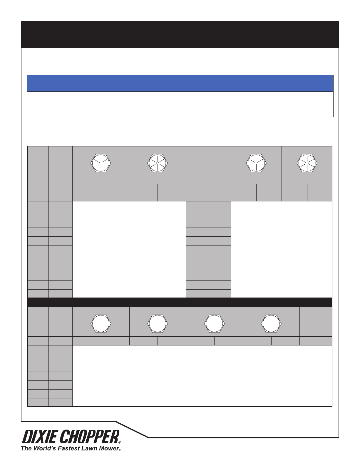
ADJUSTMENTS
ADJUSTMENTS 10
NOTICE
The torque values included in these charts are approximate and are for reference only. Use these torque values at
your risk. Jacobsen is not responsible for any loss, claim or damage caused by these charts. Always use caution
with torque values.
AMERICAN NATIONAL STANDARD FASTENERS
Non Critical
Fasteners into
10
10.4 TORQUE SPECIFICATION
NOTICE
The torque values included in these charts are approximate and are for reference only. Use these torque values at
your risk. Jacobsen is not responsible for any loss, claim or damage caused by these charts. Always use caution with
torque values.
Dixie Chopper uses Grade 5 (Inch) and Grade 8.8 (Metric) Plated bolts, unless a note is given. Always check the marks on
the head of the bolts for the bolt grade. For tightening plated bolts, use the value given for lubricated.
SIZE UNITS
GRADE 5 GRADE 8
Lubricated Dry Lubricated Dry Lubri-
#6-32 in-lb (Nm) – 20 (2.3) – – 7/16-14 ft-lb (Nm) 37 (50.1) 50 (67.8) 53 (71.8) 70 (94.9)
#8-32 in-lb (Nm) – 24 (2.7) – 30 (3.4) 7/16-20 ft-lb (Nm) 42 (56.9) 55 (74.6) 59 (80.0) 78 (105)
#10-24 in-lb (Nm) – 35 (4.0) – 45 (5.1) 1/2-13 ft-lb (Nm) 57 (77.2) 75 (101) 80 (108) 107 (145)
#10-32 in-lb (Nm) – 40 (4.5) – 50 (5.7) 1/2-20 ft-lb (Nm) 64 (86.7) 85 (115) 90 (122) 120 (162)
#12-24 in-lb (Nm) – 50 (5.7) – 65 (7.3) 9/16-12 ft-lb (Nm) 82 (111) 109 (148) 115 (156) 154 (209)
1/4-20 in-lb (Nm) 75 (8.4) 100 (11.3) 107 (12.1) 143 (16.1) 9/16-18 ft-lb (Nm) 92 (124) 122 (165) 129 (174) 172 (233)
1/4-28 in-lb (Nm) 85 (9.6) 115 (13.0) 120 (13.5) 163 (18.4) 5/8-11 ft-lb (Nm) 113 (153) 151 (204) 159 (215) 211 (286)
5/16-18 in-lb (Nm) 157 (17.7) 210 (23.7) 220 (24.8) 305 (34.4) 5/8-18 ft-lb (Nm) 128 (173) 170 (230) 180 (244) 240 (325)
5/16-24 in-lb (Nm) 173 (19.5) 230 (26.0) 245 (27.6) 325 (36.7) 3/4-10 ft-lb (Nm) 200 (271) 266 (360) 282 (382) 376 (509)
3/8-16 ft-lb (Nm) 23 (31.1) 31 (42.0) 32 (43.3) 44 (59.6) 3/4-16 ft-lb (Nm) 223 (302) 298 404 315 (427) 420 (569)
3/8-24 ft-lb (Nm) 26 (35.2) 35 (47.4) 37 (50.1) 50 (67.8) 7/8-14 ft-lb (Nm) 355 (481) 473 (641) 500 (678) 668 (905)
METRIC FASTENERS
SIZE UNITS
4.6 8.8 10.9 12.9
SIZE UNITS
GRADE 5 GRADE 8
Dry Lubri-
cated
cated
Dry
Aluminum
Lubricated Dry Lubricated Dry Lubricated Dry Lubricated Dry
M4 Nm (in-lb) – – – – – – 3.83 (34) 5.11 (45) 2.0 (18)
M5 Nm (in-lb) 1.80 (16) 2.40 (21) 4.63 (41) 6.18 (54) 6.63 (59) 8.84 (78) 7.75 (68) 10.3 (910 4.0 (35)
M6 Nm (in-lb) 3.05 (27) 4.07 (36) 7.87 (69) 10.5 (93) 11.3 (102) 15.0 (133) 13.2 (117) 17.6 (156) 6.8 (60)
M8 Nm (in-lb) 7.41 (65) 9.98 (88) 19.1 (69) 25.5 (226) 27.3 (241) 36.5 (323) 32.0 (283) 42.6 (377) 17.0 (150)
M10 Nm (ft-lb) 14.7 (11) 19.6 (14) 37.8 (29) 50.5 (37) 54.1 (40) 72.2 (53) 63.3 (46) 84.4 (62) 33.9 (25)
M12 Nm (ft-lb) 25.6 (19) 34.1 (25) 66.0 (48) 88.0 (65) 94.5 (70) 125 (92) 110 (81) 147 (108) 61.0 (45)
M14 Nm (ft-lb) 40.8 (30) 54.3 (40) 105 (77) 140 (103) 150 (110) 200 (147) 175 (129) 234 (172) 94.9 (70)
42
700493
Page 45
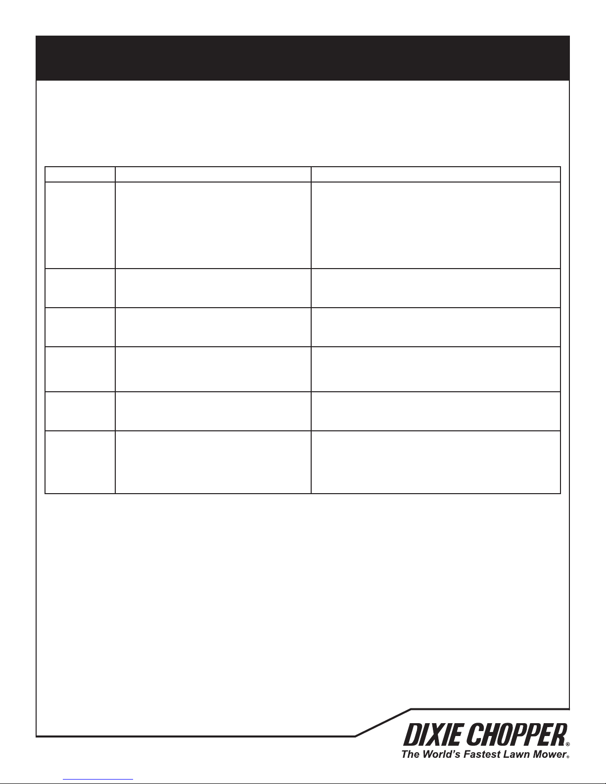
PROBLEM SOLVING
11.1 GENERAL
The problem solution chart lists basic problems that can occur during start and operation of the mower. For complete
information about the hydraulic and electrical systems, contact your Dixie Chopper Dealer.
Symptoms Possible Causes Action
1. Parking brake disengaged or power takeoff switch ON.
Engine will
not start.
Engine hard
to start or
runs poorly.
Engine stops.
Engine
overheating.
2. Battery low on charge or defective.
3. Fuel tank empty or dirty. Change fuel
lter. Bleed fuel lines.
4. Fuse blown.
5. Relay(s) defective.
1. Fuel level low, fuel or fuel lter dirty.
2. Air cleaner dirty.
3. Engine problem.
1. Fuel tank empty.
2. Interlocks not set before leaving
operator’s position.
1. Air intake restricted. 1. Clean engine cooling air intake and ns.
11
1. Check OPC System and start-up procedure.
2. Inspect condition of battery and battery connections.
3. Fill with fresh fuel.
4. Replace fuse.
5. Test and replace relay.
1. Fill with fresh fuel. Change fuel lter.
2. Inspect and replace air lter.
3. Consult engine manual.
1. Fill with fresh fuel and bleed fuel lines.
2. Engage parking brake and set power take-off switch
to OFF.
Battery not
holding
charge.
Cutting unit
does not cut
evenly.
1. Loose or corroded battery terminals.
2. Low electrolyte.
3. Charging system defective.
1. Deck not level.
2. Engine speed too low.
3. Mow speed not adjusted for turf
conditions.
1. Inspect and clean terminals.
2. Rell to correct level.
3. See engine manual.
1. Check that decks are level. Check and adjust cutting
height.
2. Check engine speed with throttle in its fast position.
3. Adjust mow speed for best cut.
700493
43
Page 46
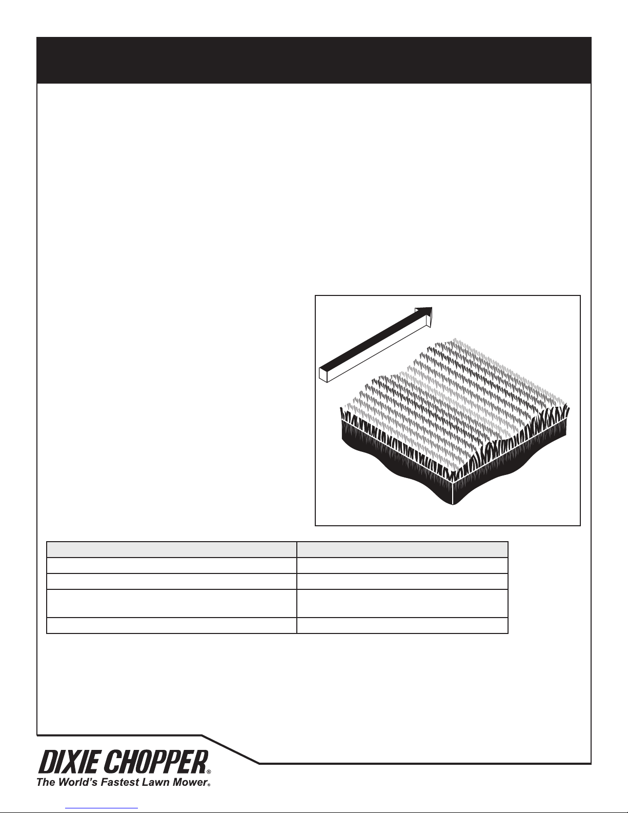
QUALITY OF CUT
QUALITY OF CUT 12
Washboarding is a repeated pattern of different cutting
heights, that causes an appearance that is like a wave. In
most cases, the wave tip-to-tip distance is approximately
6-8 in. (15-20 cm). A change in the color (from light-to-
dark) is also seen.
This cause of this condition can be a movement from side
-to-side in the cutting unit. This condition is found on
mowers with cutting units held under the mower, but other
cause can give the same result.
Another cause of Washboarding is differences in the type
of turf.
12.1 QUALITY OF CUT PROBLEM SOLVING
Make a “test cut” to check the performance of the mower before you start the repairs.
This area must have turf conditions that are known and do not change across the area. This type of area allows an
accurate inspection of the performance of the mower to be made.
Another “test cut” must be done after the repairs or adjustments to conrm the mower’s performance.
Before you do a “test cut” to show the appearance and performance of the mower, the following items must be
conrmed. These items make sure that the “test cut” is accurate.
1. Cut (Ground) Speed
2. Blade Sharpness
3. Height-of-Cut (HOC)
4. Blade Speed
12
12.2 WASHBOARDING
Washboarding is a repeated pattern of different cutting
heights, that causes an appearance that is like a wave. In
most cases, the wave tip-to-tip distance is approximately 6-8
in. (15-20 cm). A change in the color (from light-to-dark) is
also seen.
This cause of this condition can be a movement from side-toside in the cutting unit. This condition is found on mowers
with cutting units held under the mower, but other cause can
give the same result.
Another cause of Washboarding is differences in the type of
turf.
Probable Cause Remedy
The cut (ground) speed is higher than normal. Reduce the cut (ground) speed.
Cut in the same direction. Change the direction of cut more frequently.
Not enough engine speed, engine speed is not set to
specication.
Belt Slipping. Check cutting unit belt adjustment.
NOTE: Arrow indicates direction of travel.
Check/adjust the engine speed.
TN0159
44
700493
Page 47
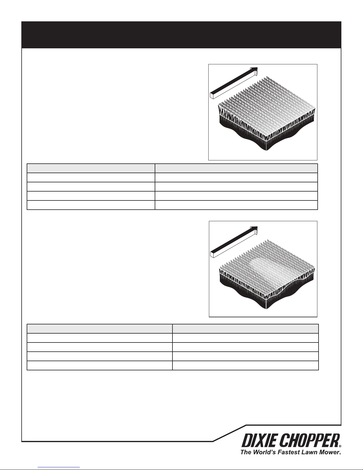
QUALITY OF CUT
Step cutting occurs when grass is cut higher on one side
of a cutting unit than the other side. Step cutting can
occur when one cutting unit is higher than another cutting
unit.
The wear of mechanical parts can cause step cutting.
QUALITY OF CUT 12
12.4 SCALPING _______________________________________________________________
Scalping is a condition in which areas of grass are cut
shorter than the adjacent areas. The area can be light
green or brown. A low HOC setting or turf that is not level
can cause scalping.
12
12.3 STEP CUTTING
Step cutting occurs when grass is cut higher on one side of a cutting
unit than the other side. Step cutting can occur when one cutting unit
is higher than another cutting unit.
The wear of mechanical parts can cause step cutting.
NOTE: Arrow indicates direction of travel.
Probable Cause Remedy
The cutting unit movement is prevented. Check and remove the cutting unit movement obstruction.
Differences in turf density Change the direction of cut.
Mower ride height is uneven side to side. Check and adjust tire ination pressure.
Cutting unit height is uneven side to side. Check and adjust for deck level.
TN0221
12.4 SCALPING
Scalping is a condition in which areas of grass are cut shorter than
the adjacent areas. The area can be light-green or brown. A low HOC
setting or turf that is not level can cause scalping.
NOTE: Arrow indicates direction of travel.
Probable Cause Remedy
HOC (height-of-cut) set is lower than normal. Check and adjust the HOC. See 7.9
Turf is not level and the mower can not follow the turf. Change the direction of cut.
Grass is higher than the cutting unit capacity. Cut the grass more frequently.
Cut (ground) speed is higher than the mower can cut. Reduce the cut (ground) speed.
TN0222
700493
45
Page 48
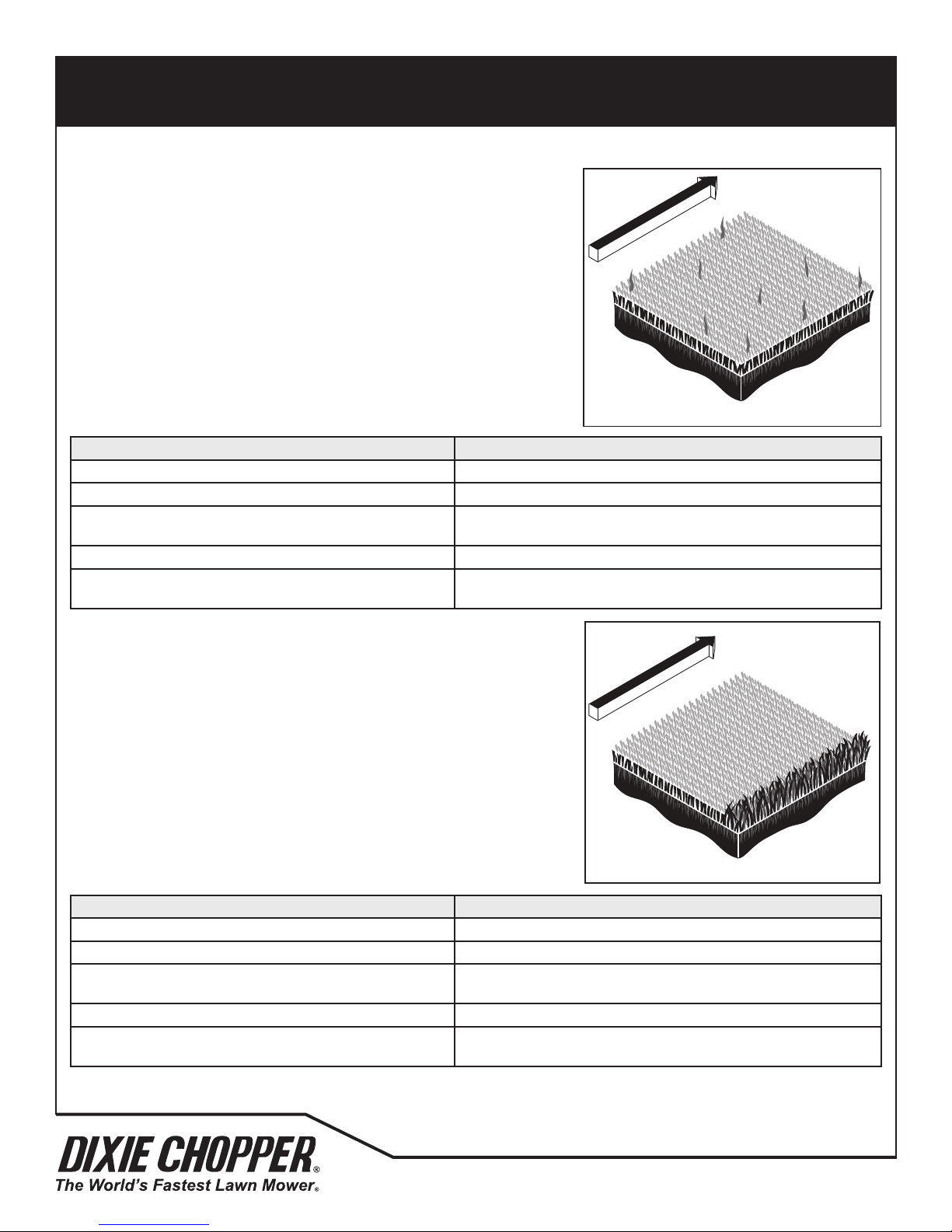
QUALITY OF CUT
Stragglers are separated blades of grass the are not cut,
or are cut incorrectly.
QUALITY OF CUT 12
A streak is a line of grass that is not cut. The cause of a
streak can be a damaged blade.
12.5 STRAGGLERS
Stragglers are separated blades of grass the are not cut,
or are cut incorrectly.
Probable Cause Remedy
Edge of the cutting blade(s) are not sharp. Sharpen the blade(s). See 9.13
Cut (ground) speed is higher than normal Reduce the cut (ground) speed.
The grass is higher than the level at which the mower can cut
correctly.
Cut in the same direction. Change the direction of cut more frequently.
The blade speed is too slow Operate the mower with the engine at full throttle. Inspect the
12
NOTE: Arrow indicates direction of travel.
Cut the grass more frequently.
cutting unit belt.
TN0223
12.6 STREAKS
A streak is a line of grass that is not cut. The cause of a streak can be a damaged
blade.
NOTE: Arrow indicates direction of travel.
Probable Cause Remedy
Edge of the cutting blade(s) are not sharp. Sharpen the blade(s). See 9.13
Cut (ground) speed is higher than normal Reduce the cut (ground) speed.
The grass is higher than the level at which the mower can cut
correctly.
Cut in the same direction. Change the direction of cut more frequently.
The blade speed is too slow Operate the mower with the engine at full throttle. Inspect the
Cut the grass more frequently.
cutting unit belt.
TN0224
46
700493
Page 49
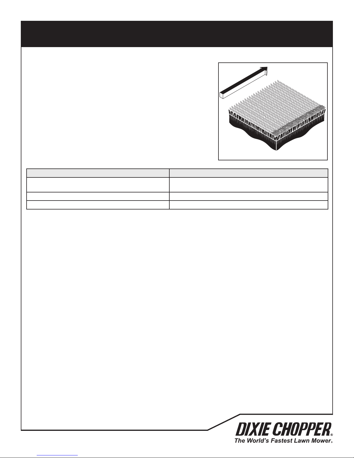
QUALITY OF CUT
Windrowing is the deposit of clippings increased at one
end of cutting unit(s) or between cutting units.
Windrowing can make a line in the direction of travel.
12.7 WINDROWING
Windrowing is the deposit of clippings increased at one end of cutting unit(s) or
between cutting units. Windrowing can make a line in the direction of travel.
Probable Cause Remedy
The grass is higher than the level at which the mower can cut
correctly.
Mowing the grass while grass is wet. Cut when grass is dry.
Grass collecting on mower or cutting unit frame. Clean the cutting unit(s) grass deector.
12
NOTE: Arrow indicates direction of travel.
Cut the grass more frequently.
TN0225
700493
47
Page 50

NOTES
13
48
700493
Page 51

NOTES
13
700493
49
Page 52

Specications and instructions subject to change without notice.
Dixie Chopper and Jacobsen Professional Lawn Care Inc, are registered trademarks.
Any and all use and/or reproductions are strictly prohibited.
700493
Dixie Chopper
6302 E CR 100 N • Coatesville, IN 46121
www.dixiechopper.com
765.246.7737
REV A 08252015
 Loading...