

Page 1
INSTALLATION GUIDE
Ver 1. 0
Page 2

Page 3

WARNING: Use only modems supported by this monitoring
unit. Dixell S.p.a can accept no responsibility for
possible damage due the usage of not supported
modems.
WARNING:
Dixell S.p.a. reserves itself the right to alter this
manual without notice. The last version available
can be downloaded from the website.
Page 4

INDEX
1 CHECK LIST.......................................................................................5
2 TO DO LIST........................................................................................6
3 RS 485 CONNECTION.....................................................................7
3.1 The TTL output...............................................................................9
3.2 Serial address of the instruments................................................9
4 Local connection with monitor, mouse and keyboard...............10
4.1 HOW TO SETUP YOUR NETWORK CARD..........................12
4.1.1 Windows 98 and ME TCP/IP Setup.................................12
4.1.2 Windows 2000 TCP/IP Setup ...........................................16
4.1.3 Windows XP TCP/IP Setup...............................................18
5 Modem connection (“or point to point connection”)...................23
5.1 HOW TO SETUP a dial-up connection...................................24
5.1.1 Setting up dial-up connection for windows 98................24
5.1.2 Setting up dial-up connection for windows me...............30
5.1.3 setting up dial-up connection for windows 2000............38
5.1.4 SETTING UP dial -up connection for windows XP......... 51
6 Intranet / ethernet connection.......................................................65
Page 5
XWEB SERIES Installation Guide
1592010850 23/05/2007 Pg. 5/72
1 CHECK LIST
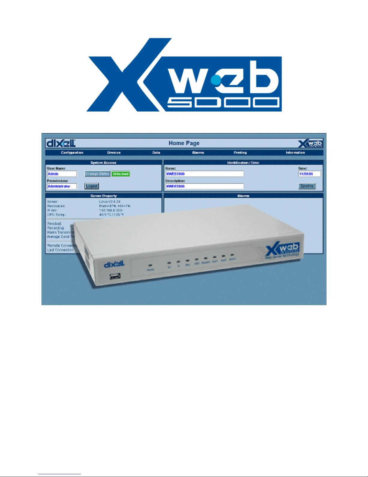
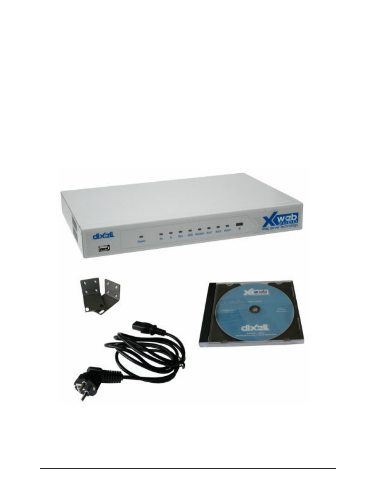
• The XWEB5000 server unit.
• One power cord for power supply connection.
• 2 mounting brackets.
• Quick reference manual (Fast installation).
• One serial line adapter
• One CD Rom containing the Operating manual and software
Page 6

XWEB SERIES Installation Guide
Pg. 6/72 23/05/2007 1592010850
2 TO DO LIST
• Check if the power supply line matches the XWEB5000
specification (90~264 VAC 50~60Hz.).
• Connect the serial line RS 485 with the adapter provided.
• Plug-in monitor, keyboard and mouse (if required) before turning
on the unit.
• Plug-in RJ 45 network cable (not provided).
Page 7
XWEB SERIES Installation Guide
1592010850 23/05/2007 Pg. 7/72
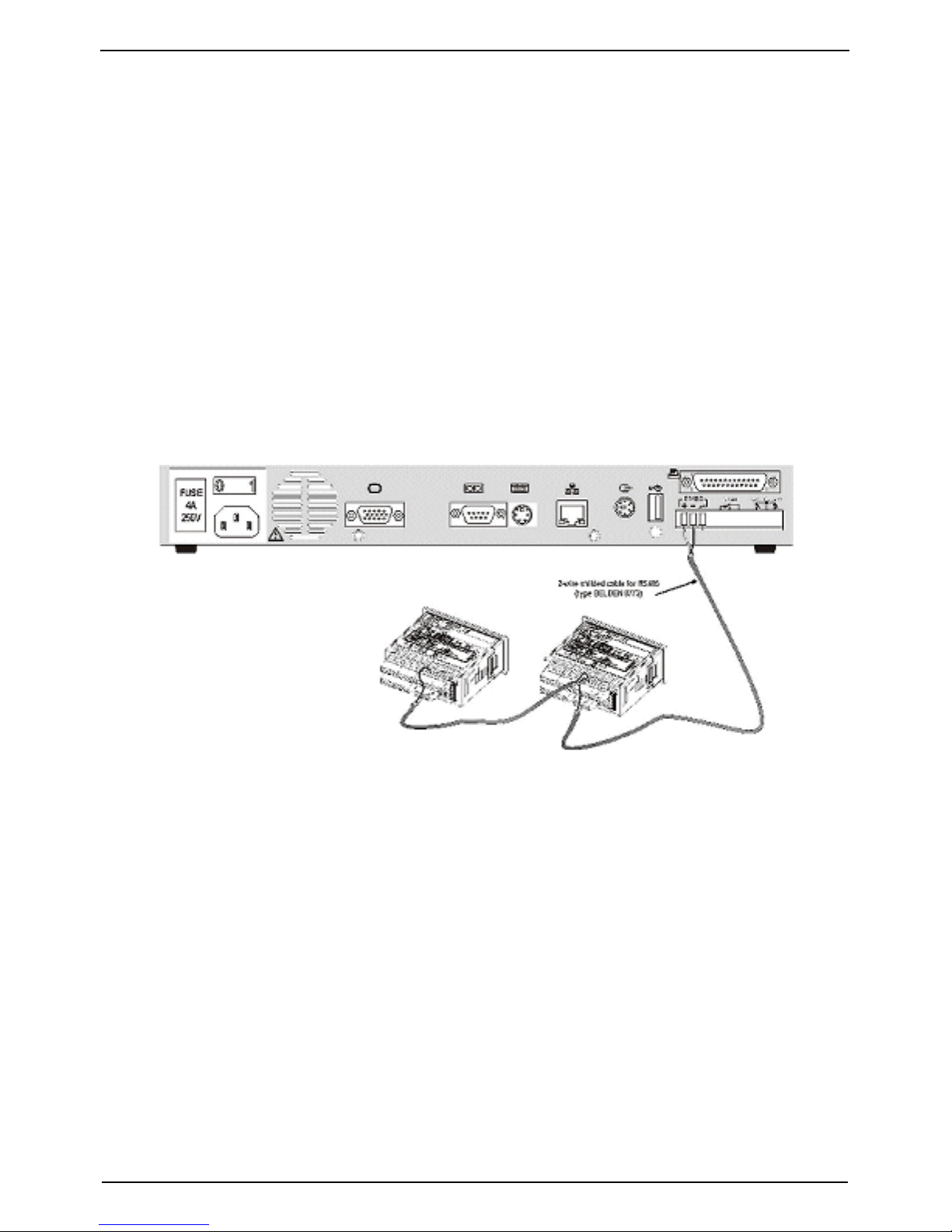
3 RS 485 CONNECTION
To be connected to the serial line all the Dixell Modbus instruments
must be provided with direct RS485 terminals or the “TTL”-RS485
interface (XJRS485 or XJ485). Check the instrument manuals for
more information. The RS485 line is mainly based on two polarised
terminals. Please pay respect to the right sequence for all the
devices connected to the serial line.
Follow these important instructions:
• The RS485 serial line must reach all the instruments where they
are installed.
• Make sure of the wire polarities when screwing them into the
instrument terminals.
• The cable must have 2 or 3 wires with shield, minimum section
0,5mm2 (eg. the BELDEN 8772).
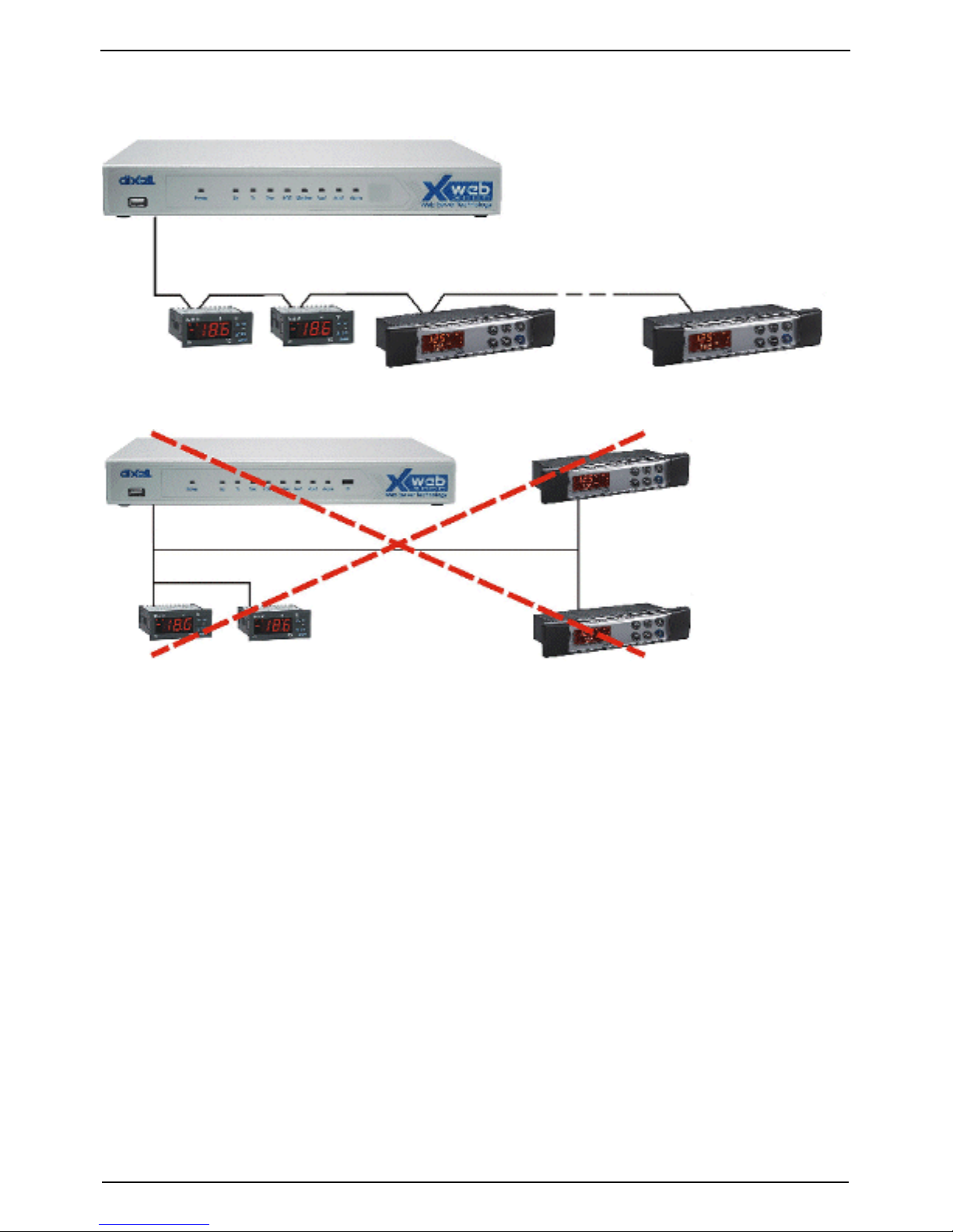
• From the XWEB5000 position the cable reaches all the
instrument positions.
• Do not execute loops or derivations:
Page 8
XWEB SERIES Installation Guide
Pg. 8/72 23/05/2007 1592010850
Right connection:
Wrong connection:
• Always keep the serial cable away from power cables.
• Always keep the serial cable away from Electro-magnetic or
frequency sources.
• Do not connect shield to ground.
• Do not connect the “Gnd (ground) ” terminal.
• Remember to draw a map of the line. This will help you to find
errors if something is wrong.
• The instrument with RS485 have “+” and “-“ terminals, respect
the polarity.
• To keep the line balanced it is necessary a 100 Ohm resistor at
the end of the line (you ca use the RS 485+ and RS 485-
terminals of the last instrument connected).
Page 9

XWEB SERIES Installation Guide
1592010850 23/05/2007 Pg. 9/72
3.1 The TTL output
The instrument with RS485 on board does not need any kind of
external interface module. For instruments with an external
interface: keep the TTL cable away from power cables or frequency
sources.
The XJ485 external interface must be connected with a TTL cable to
the instrument with TTL compatibility.
3.2 Serial address of the instruments
Each instrument must be defined by its unique address.
Check the address into the Adr parameter value of each
instruments. Take reference to the instruction manual of the
instrument itself to find the ri ght procedure to enter the programming
and set the value.
The easiest way to work with the category functions is to set the
addresses progressively for similar groups of instruments which
have the same application.
Page 10
XWEB SERIES Installation Guide
Pg. 10/72 23/05/2007 1592010850
4 Local connection with monitor, mouse
and keyboard
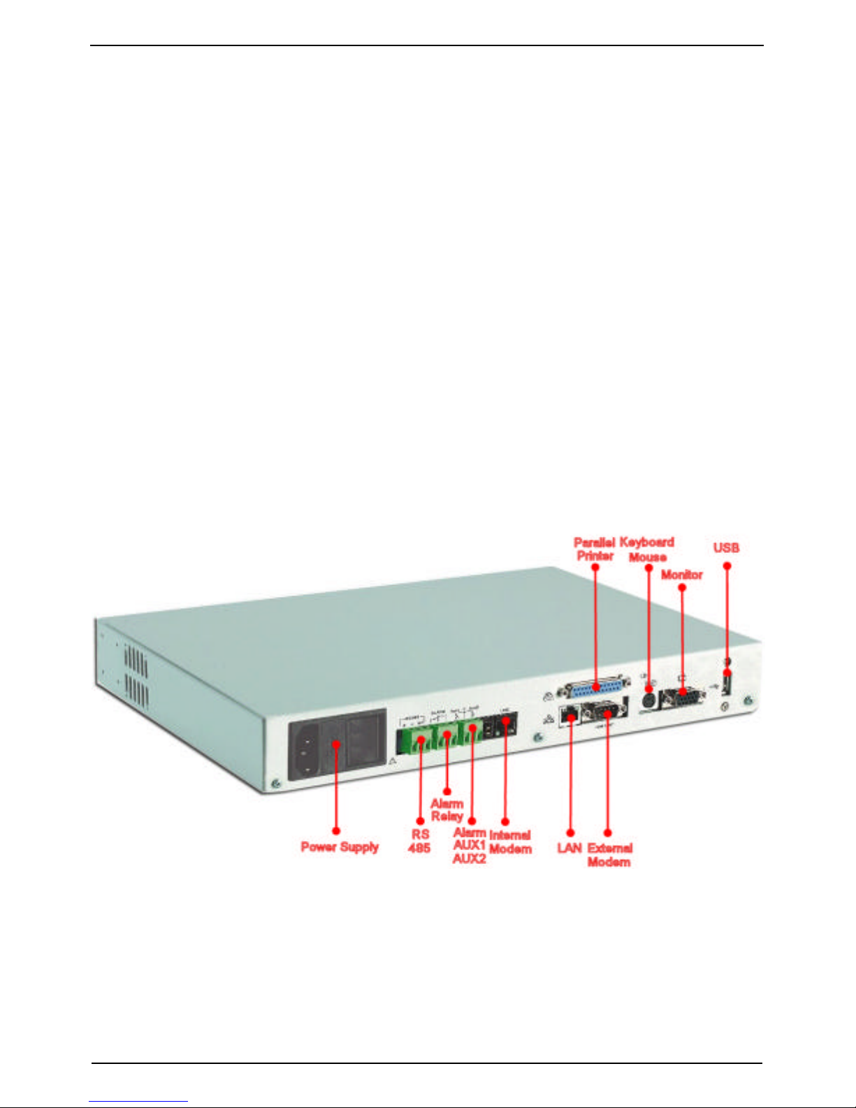
On rear of the XWEB5000 sockets are provided for a monitor, a
mouse and a keyboard. Please connect all the peripherals before
powering-on the unit otherwise the system may fails to recognise
them. This means that , for example, if you do not plug the monitor
cable in now, you won’t see anything displayed on it later.
The unit can also work without these three elements therefore if the
user intend s to work just with the remote, he can definitively remove
them after the setup operations. In any case inside the of
XWEB5000 is loaded a standard browser to allow the user setting
up the unit.
If necessary check the instructions manual of each device
connected to the unit.
The operative procedure to work with XWEB5000 is the same for all
connection methods.
Page 11

XWEB SERIES Installation Guide
1592010850 23/05/2007 Pg. 11/72
It is possible to connect to the unit via a single PC provided with
LAN card, by using the net connector RJ 45 (LAN). Due to the PC-
client power, this kind of connection is more suitable for the setup
procedures.
IMPORTANT: the cable between the Server and the PC must be
with crossing wires (“Bridge Cable”).
The connection procedure from the remote PC is described in deep
in this guide. You may need some changes to your PC network
card, then you will be able to connect to XWEB5000 via Ethernet/
Internet line. Once you have finished setting up your network card,
connection to XWEB5000 is established simply by launching the
Browser and inserting the default IP number of the unit
http://192.168.0.200 into the address bar.
Before reading on, please take a few moments to write down your
PC network setup, there may be a need to change it. If the IP
address of your PC belong to the hierarchy 192.168.0.XYZ (where
XYZ represent a number between 1 and 254), you can reach
XWEB5000 simply plugging in the network cable.
Page 12

XWEB SERIES Installation Guide
Pg. 12/72 23/05/2007 1592010850
4.1 HOW TO SETUP YOUR NETWORK CARD
Windows 98 and ME TCP/IP Setup pg.12
Windows 2000 TCP/IP Setup pg.16
Windows XP TCP/IP Setup pg.18
4.1.1 WINDOWS 98 AND ME TCP/IP SETUP
On the desktop, select My Computer -> Control Panel -> Network.
Choose the Configuration tab.
Highlight the TCP/IP associated with your Ethernet card and choose
Properties. The TCP/IP Properties window will open. On each tab,
Page 13
XWEB SERIES Installation Guide
1592010850 23/05/2007 Pg. 13/72
make the following settings.
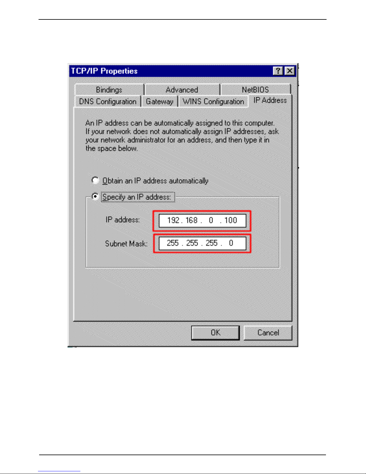
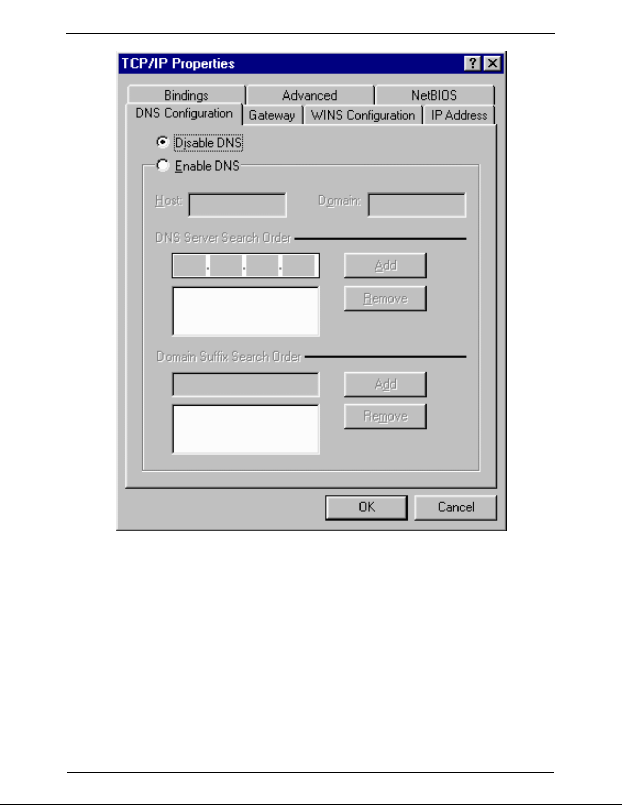
Choose the IP Address tab.
Highlight as shown above, “Specify an IP address”. Then go to the
DNS configuration tab and highlight “Disable DNS”.
Page 14
XWEB SERIES Installation Guide
Pg. 14/72 23/05/2007 1592010850
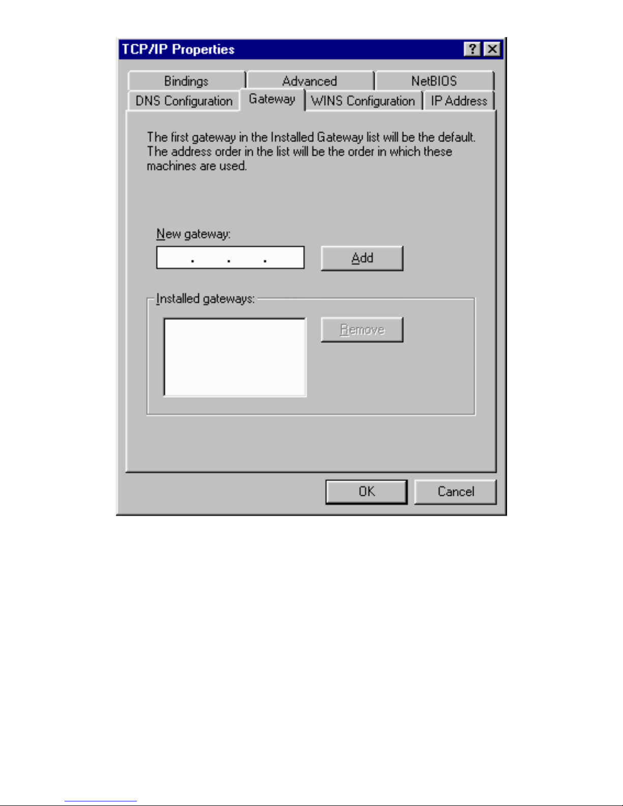
Go to gateway tab and delete any entry as shown below.
Page 15
Push Ok button, Windows will ask you to make a reboot. Choose ok
and wait for the system to reboot.
Page 16
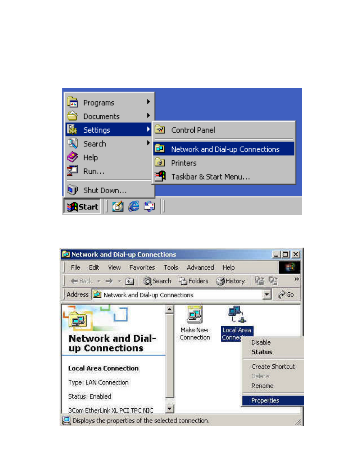
4.1.2 WINDOWS 2000 TCP/IP SETUP
Go to Start -> Settings -> Network and Dial-up Connections:
The following window should appear:
Page 17
XWEB SERIES Installation Guide
1592010850 23/05/2007 Pg. 17/72
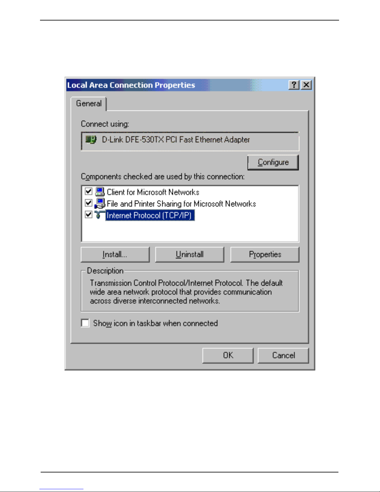
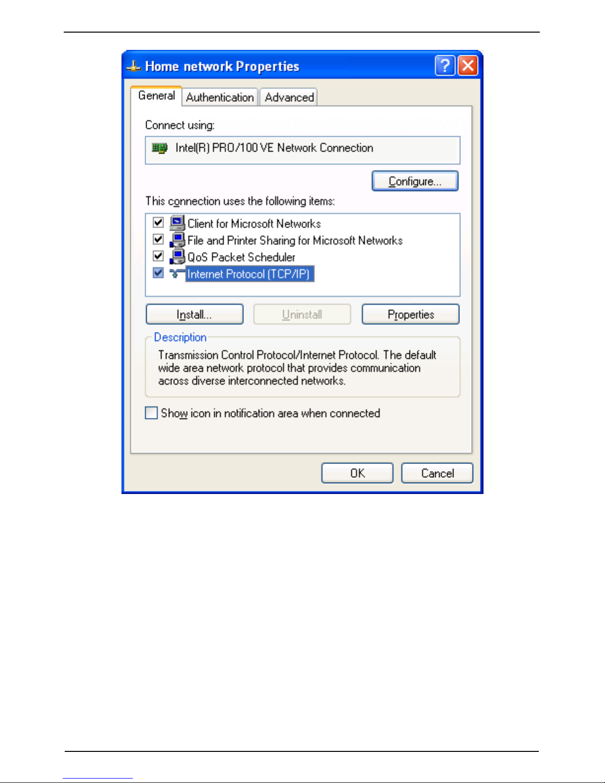
Right-click the network connection associated with your network
card, and then click Properties. The following window should
appear:
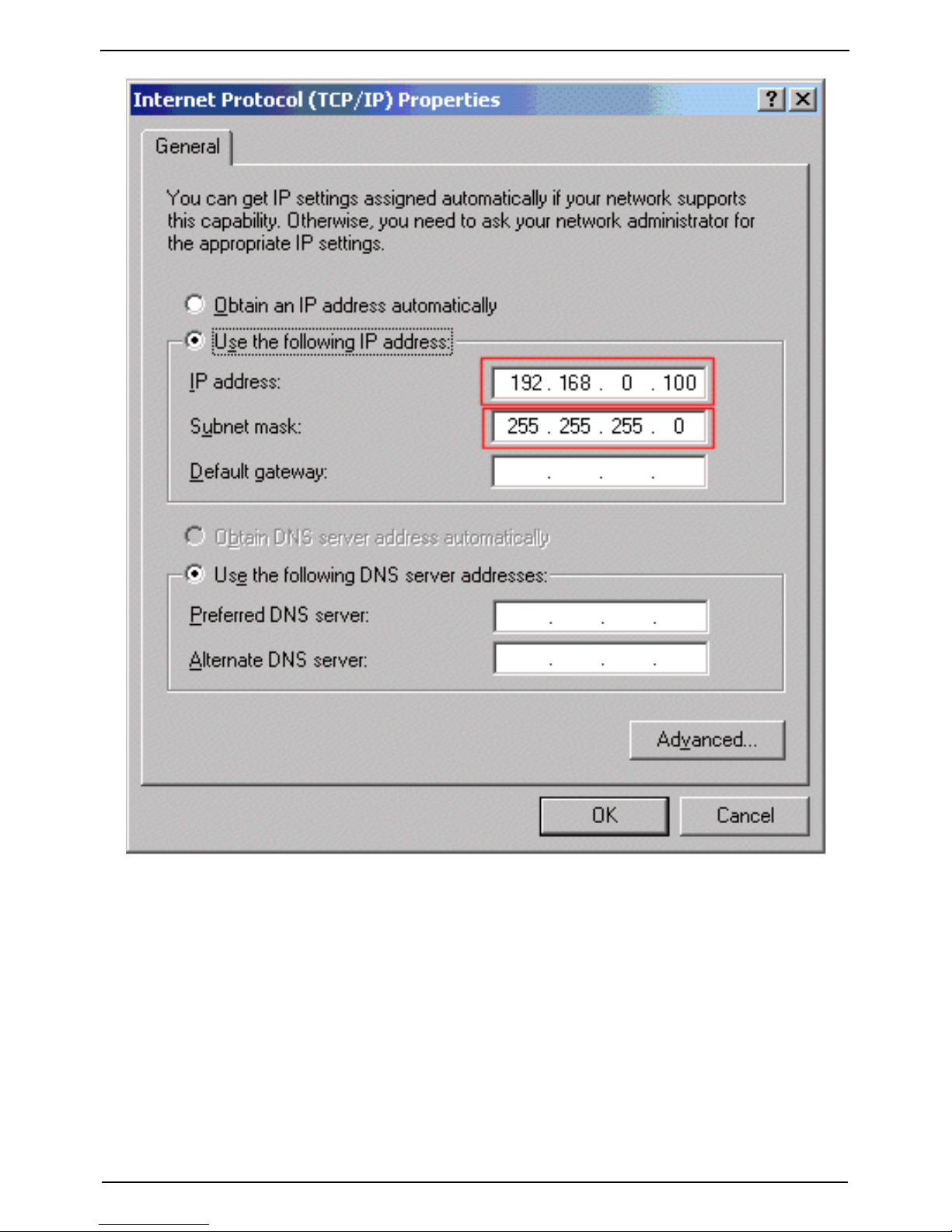
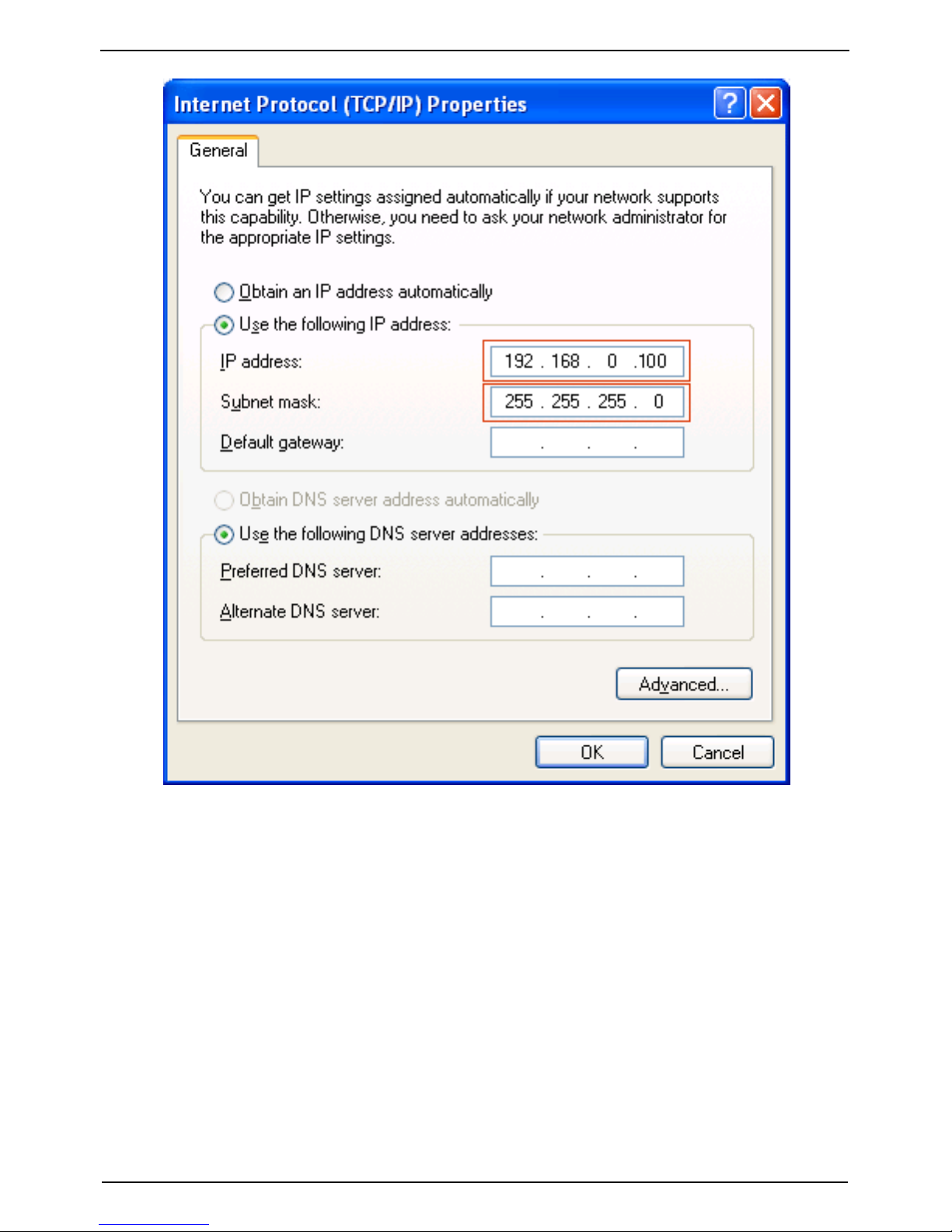
Select “Internet Protocol (TCP/IP)”, then properties. The following
window should appear:
Page 18
XWEB SERIES Installation Guide
Pg. 18/72 23/05/2007 1592010850
Highlight “Use the following IP address” and compile the fields as
the image above. Push “OK” button
4.1.3 WINDOWS XP TCP/IP SETUP
Page 19
XWEB SERIES Installation Guide
1592010850 23/05/2007 Pg. 19/72
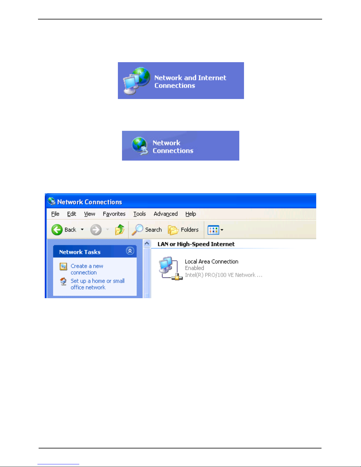
Click on Start button, chose Control panel, click on “Network and
internet connections” icon:
Then chose “Network connections”:
The following windows will appear:
Right mouse click on network interface icon, then chose
“Properties”:
Page 20

XWEB SERIES Installation Guide
Pg. 20/72 23/05/2007 1592010850
The following windows will appear:
Page 21
XWEB SERIES Installation Guide
1592010850 23/05/2007 Pg. 21/72
Select “Internet Protocol (TCP/IP)”, then click on Properties. The
following windows will appear:
Page 22
XWEB SERIES Installation Guide
Pg. 22/72 23/05/2007 1592010850
Page 23

XWEB SERIES Installation Guide
1592010850 23/05/2007 Pg. 23/72
5 Modem connection (“or point to point
connection”)
It represents the most common method where the LAN (intranet /
Ethernet / internet) is not available.
It is strongly advised to use a dedicated telephone line.
IMPORTANT: Use exclusively modem devices approved by
Dixell.
Remember that many modems are not compatible with Linux.
The list of compatible models can be found under the menu:
Configuration – System - Modem.
External Modem
Connect the External Modem to the serial Port on the back side
using the modem cable commonly included into the modem
packaging itself.
The modem reset is directly controlled by the XWEB5000 Server
through the RS232 port by turning off and then on the modem
device.
Connect the modem to the telephone line with the phone cable
included into the modem packaging. Remember to check if there is
a switching machine.
The connection procedure is divided in two parts. In the first part it is
necessary to create the Remote Access, in your PC, set with the
telephone number of the line where the XWEB5000 is connected to.
You have to use Dixell as Username and Password.
The second is the procedure you will ever use: after launching the
new Remote Access that will engage the line through the modem,
start the Browser from your PC and insert the address
http://192.168.1.200 into Explorer/Netscape address bar.
Page 24

XWEB SERIES Installation Guide
Pg. 24/72 23/05/2007 1592010850
5.1 HOW TO SETUP a dial -up connection
Setting up dial-up connection for windows 98 pg.24
Setting up dial-up connection for windows me pg.30
setting up dial-up connection for windows 2000 pg.38
SETTING UP dial -up connection for windows XP pg.51
5.1.1 SETTING UP DIAL-UP CONNECTION FOR WINDOWS 98
1. Double-click on the "My Computer" icon on your Desktop, then
double-click on "Dial -Up Networking".
2. If this is the first time Dial-Up Networking has been run, the
Welcome screen will open. Click on "Next" and proceed to step 4.
Page 25

XWEB SERIES Installation Guide
1592010850 23/05/2007 Pg. 25/72
3. If you don't get the Welcome screen, double -click on "Make New
Connection".
Page 26

XWEB SERIES Installation Guide
Pg. 26/72 23/05/2007 1592010850
4. Type “XWEB5000 DIRECT MODEM” in the first box. When you
finish the New Connection wizard, the connection icon will be
named “ XWEB5000 DIRECT MODEM ”. Chose “digicom Botticelli
web” or another modem approved dy Dixell.
Click “Next".
Page 27

XWEB SERIES Installation Guide
1592010850 23/05/2007 Pg. 27/72
5. Do not type the area code, insert tele phone number with the area
code of XWEB5000 as a prefix.
E.G: If telephone number is 555789 and area code is 099, put this
Telephone number: 099555789.
If there is a switching machine and you have to dial a digit to get the
line ( 0 or 9 for example, it depends on the switching machine), put
this telephone number: 0, 099555789 or 9, 099555789. Chose your
country.
Click "Next".
Page 28

XWEB SERIES Installation Guide
Pg. 28/72 23/05/2007 1592010850
6.Click "Finish".
Page 29

XWEB SERIES Installation Guide
1592010850 23/05/2007 Pg. 29/72
Page 30

XWEB SERIES Installation Guide
Pg. 30/72 23/05/2007 1592010850
5.1.2 SETTING UP DIAL-UP CONNECTION FOR WINDOWS ME
1. From the Start menu, click Settings, and choose Dial-Up
Networking.
2. Double-click the Make New Connection icon.
3. In the Type a name for the computer you are dialling field, type
XWEB3000 DIRECT MODEM.
4. Click the down arrow on the Select a device drop-down list and
choose “digicom botticelli web” or another modem approved dy
Dixell.
5.Click the Next button.
Page 31

XWEB SERIES Installation Guide
1592010850 23/05/2007 Pg. 31/72
6. Do not type the area code, insert telephone number with the area
code of XWEB5000 as a prefix.
E.G: If telephone number is 555789 and area code is 099, put this
Telephone number: 099555789.
If there is a switching machine and you have to dial a digit to get the
line ( 0 or 9 for example, it depends on the switching machine), put
this telephone number: 0, 099555789 or 9, 099555789.Chose your
country.
7.Click the Next button.
Page 32

XWEB SERIES Installation Guide
Pg. 32/72 23/05/2007 1592010850
8. Click the Finish button.
Page 33

XWEB SERIES Installation Guide
1592010850 23/05/2007 Pg. 33/72
9. Click the XWEB5000 DIRECT MODEM icon with your right
mouse button, then choose Properties.
10. Click on the Networking tab.
11. Click the down arrow on the Type of Dial-Up Server: d rop-down
list and choose PPP: Internet, Windows 2000/NT, Windows Me.
12. Uncheck all the boxes except for Enable software compression
and TCP/IP.
13. Click the TCP/IP Settings... button.
Page 34

XWEB SERIES Installation Guide
Pg. 34/72 23/05/2007 1592010850
14. Select Server assigned IP address
15. Select Server assigned name server addresses.
16. Click the OK button.
Page 35

XWEB SERIES Installation Guide
1592010850 23/05/2007 Pg. 35/72
17. Click on the Security tab.
18. In the User name: dixell
19. In the Password: dixell
20. Click the OK button.
Page 36

XWEB SERIES Installation Guide
Pg. 36/72 23/05/2007 1592010850
21. Click the XWEB5000 DIRECT MODEM icon with your right
mouse button, then choose Create Shortcut.
Page 37

XWEB SERIES Installation Guide
1592010850 23/05/2007 Pg. 37/72
22. Click the Yes button.
Page 38

XWEB SERIES Installation Guide
Pg. 38/72 23/05/2007 1592010850
5.1.3 SETTING UP DIAL-UP CONNECTION FOR WINDOWS
2000
Start-Menu "Settings", then "Network and Dial-up
Connections".
Select to "Make a New Connection"
Page 39

XWEB SERIES Installation Guide
1592010850 23/05/2007 Pg. 39/72
This starts up the "Network Connection Wizard".
Continue with "Next"
Page 40

XWEB SERIES Installation Guide
Pg. 40/72 23/05/2007 1592010850
Chose “Dial up to the Internet"
Page 41

XWEB SERIES Installation Guide
1592010850 23/05/2007 Pg. 41/72
Choose “Connect using my phone line”:
Page 42

XWEB SERIES Installation Guide
Pg. 42/72 23/05/2007 1592010850
Do not type the area code, insert telephone number with the area
code of XWEB5000 as a prefix.
E.G: If telephone number is 555789 and area code is 099, put this
Telephone number: 099555789.
If there is a switching machine and you have to dial a digit to get the
line ( 0 or 9 for example, it depends on the switching machine), put
this telephone number: 0, 099555789 or 9, 099555789.Chose your
country.
Click the Next button.
Page 43

XWEB SERIES Installation Guide
1592010850 23/05/2007 Pg. 43/72
The User name and Password is dixell.
Page 44

XWEB SERIES Installation Guide
Pg. 44/72 23/05/2007 1592010850
As connection name use “XWEB5000 direct modem”:
Page 45

XWEB SERIES Installation Guide
1592010850 23/05/2007 Pg. 45/72
The first part is done.
Page 46

XWEB SERIES Installation Guide
Pg. 46/72 23/05/2007 1592010850
Now you will found a new icon in your network directory:
Page 47

XWEB SERIES Installation Guide
1592010850 23/05/2007 Pg. 47/72
Right mouse click and choose properties:
Page 48

XWEB SERIES Installation Guide
Pg. 48/72 23/05/2007 1592010850
Leave the general tab as you compiled before in this guide and
choose “networking” tab:
Page 49

XWEB SERIES Installation Guide
1592010850 23/05/2007 Pg. 49/72
Select Internet Protocol (TCP/IP) and click on “Properties”:
Page 50

XWEB SERIES Installation Guide
Pg. 50/72 23/05/2007 1592010850
Compile your windows as describe above. Click ok and close all
windows.
Page 51

XWEB SERIES Installation Guide
1592010850 23/05/2007 Pg. 51/72
5.1.4 SETTING UP DIAL-UP CONNECTION FOR WINDOWS XP
In Windows XP, you will use the "New Connection Wizard".
1. From the Start menu, select Control Panel.
2. If Control Panel is set for "Classic View", double-click on the
Network Connections icon.
Page 52

XWEB SERIES Installation Guide
Pg. 52/72 23/05/2007 1592010850
3. If Control Panel is set for "Category View", select the "Network
and Internet Connections" category, then double-click on the
Network Connections icon.
Page 53

XWEB SERIES Installation Guide
1592010850 23/05/2007 Pg. 53/72
Page 54

XWEB SERIES Installation Guide
Pg. 54/72 23/05/2007 1592010850
4. Under Network Tasks, select "Create a new connection".
Page 55

XWEB SERIES Installation Guide
1592010850 23/05/2007 Pg. 55/72
5. Click "Next".
Page 56

XWEB SERIES Installation Guide
Pg. 56/72 23/05/2007 1592010850
6. Click "Next" at the bottom of this page to continue with the setup
instructions.
7. Select "Connect to the Internet" and click "Next".
Page 57

XWEB SERIES Installation Guide
1592010850 23/05/2007 Pg. 57/72
8. Select "Set up my connection manually" and click "Next".
Page 58

XWEB SERIES Installation Guide
Pg. 58/72 23/05/2007 1592010850
9. Select "Connect using a dialup modem" and click "Next".
Page 59

XWEB SERIES Installation Guide
1592010850 23/05/2007 Pg. 59/72
10. Type "XWEB5000 DIRECT MODEM" in the ISP Name box and
click "Next".
Page 60

XWEB SERIES Installation Guide
Pg. 60/72 23/05/2007 1592010850
11. Type the access number in the Phone Number box.
E.G: If telephone number is 555789 and area code is 099, put this
Telephone number: 099555789.
If there is a switching machine and you have to dial a digit to get the
line ( 0 or 9 for example, it depends on the switching machine), put
this telephone number: 0, 099555789 or 9, 099555789.
Click "Next".
Page 61

XWEB SERIES Installation Guide
1592010850 23/05/2007 Pg. 61/72
12. Type dialup account name dixell in the User Name box. Type
dialup password dixell in the Password and Confirm Password
boxes. We recommend that you check the first 2 checkboxes, but
not the 3rd box which turns on the Internet Connection Firewall.
Click "Next".
Page 62

XWEB SERIES Installation Guide
Pg. 62/72 23/05/2007 1592010850
13. Place a tick in the box to create a shortcut on your desktop, and
click "Finish".
Page 63

XWEB SERIES Installation Guide
1592010850 23/05/2007 Pg. 63/72
14. You are now ready to connect to your XWEB5000.
If you want to dial your XWEB5000 DIRECT MODEM connection
automatically when you start Internet Explorer, do the following.
Start Internet Explorer, and select "Internet Options" from the
"Tools" menu. Select the "Connections" tab. Make sure that
XWEB5000 DIRECT MODEM is your default connection (if not,
highlight it and click "Make Default"). Make sure that the "Always
dial my default connection" option is selected.
Page 64

XWEB SERIES Installation Guide
Pg. 64/72 23/05/2007 1592010850
Page 65

XWEB SERIES Installation Guide
1592010850 23/05/2007 Pg. 65/72
6 Intranet / ethernet connection
The Intranet or Ethernet connection should be initially managed by
the net administrator which will assign one free IP address to reach
the Server. This number is an example of what you should expect:
http://192.168.000.111.
After receiving the address from your network Administrator the
XWEB5000 must be set with this number.
REMEMBER: A setup wizard will guide you through the procedure.
Please ensure you have an IP address to use in network section.
Use a standard RJ45 network cable to connect the unit to your lan.
The Intranet method allows the connection to interact with
XWEB5000 from all the PC Clients. Insert the net address assigned
by the administrator into the Browser address bar. Bookmark the
address with personalised name for the future connections.
Internet connection
It is necessary to have a STATIC IP address for the XWEB5000
which is normally assigned by the Provider of your internet services
(ISP).
The Internet connection allows XWEB5000 to be reached from all
PC-clients. Insert the net address assigned by the administrator into
Page 66

XWEB SERIES Installation Guide
Pg. 66/72 23/05/2007 1592010850
the Browser address bar. Bookmark the address with personalised
name for the future connections.
Ask your provider for more details about the rent of a the static IP.
This the internet system requirements for the best result:
Wide band connection.
At least 1 static IP addresses for the XWEB5000.
The internet connection is established through a device called
Router that receives and sends the data as interface between an
Intranet and Internet. The Provider also assigns the address of the
router that is called IP WAN.
Remember that the default value of the IP of the XWEB5000 is:
192.168.0.200.
Depending on the contract the Provider can also supply the router,
otherwise the user can buy it separately.
ALWAYS: ask qualified personnel for the router installation by using
this information.
Used ports that are mapped to the LAN side:
80 (used for the HTTP access)
22 (used for SSH connection)
443 (used for SSL protected connection)
10000 (used for the internal modules of the system)
The above ports are all related to the XWEB5000 IP address
192.168.0.200.
While the ports on the WAN side are:
Telnet (to configure the router from a remote, also via Internet).
HTTP (To access the XWEB5000).
If working with the router GATEWAY and DNS check your Internet
contract details. Depending on your network topology you may need
a reversing NAT on port 80. It is not enough to link port 80 on
Router side to port 80 on intranet side. Some firewall or Router
need also di reverse setup.
Page 67

XWEB SERIES Installation Guide
1592010850 23/05/2007 Pg. 67/72
Page 68

XWEB SERIES Installation Guide
Pg. 68/72 23/05/2007 1592010850
Page 69

XWEB SERIES Installation Guide
1592010850 23/05/2007 Pg. 69/72
Troubleshooting Guide
Problem Solution
The log-
in page doesn’t
load
Check your browser setup.
My password doesn’t allow
me to log-in.
Beware to the caps-
lock
button an capitol letters. Is it
your password correct?
My browser can’t reach
XWEB5000 log-in page
Check cable typology
From windows go to
Start->Run…
ping 192.168.0.200 –t
A continuous set of
information should be
appear.
Someone in the
intranet/LAN receive a
warning message about an
IP conflict.
XWEB5000
uses the same
address of a resource
already used in your
intranet/LAN. Change
XWEB5000 IP address.
Page 70

XWEB SERIES Installation Guide
Pg. 70/72 23/05/2007 1592010850
Unit Setup Reminder
Please take some moments to make an hardcopy of this page, then
compile it and store it near XWEB5000 unit.
HostName
___________________________
IP Address
___________________________
Gateway
___________________________
DNS 1
___________________________
DNS 2
___________________________
SMTP
___________________________
E-mail address
___________________________
Modem type
___________________________
Telephone number
___________________________
Page 71

XWEB SERIES Installation Guide
1592010850 23/05/2007 Pg. 71/72
Notes
______________________________________________________
______________________________________________________
______________________________________________________
______________________________________________________
______________________________________________________
______________________________________________________
______________________________________________________
______________________________________________________
______________________________________________________
______________________________________________________
______________________________________________________
______________________________________________________
______________________________________________________
______________________________________________________
______________________________________________________
______________________________________________________
______________________________________________________
______________________________________________________
______________________________________________________
______________________________________________________
______________________________________________________
______________________________________________________
______________________________________________________
______________________________________________________
______________________________________________________
______________________________________________________
______________________________________________________
______________________________________________________
______________________________________________________
______________________________________________________
______________________________________________________
______________________________________________________
Page 72

Pg. 72/72 23/05/2007 1592010850
Dixell S.p.a. Z.I. Via dell’Industria, 27
32010 Pieve d’Alpago (BL) ITALY
tel. +39 - 0437 - 98 33 - fax +39 - 0437 - 98 93 13
E-mail: dixell@dixell.com - http://www.dixell.com
 Loading...