

Page 1
dIXEL
Installing and Operating Instructions
R1.0 1592007271
1592007271 XR80C-D GB r1.0 20.05.2005.doc XR80C – XR80D 1/4
Milk tank controllers
XR80C – XR80D
CONTENTS
1. GENERAL WARNING______________________________________________ 1
2. GENERAL DESCRIPTION __________________________________________ 1
3. CONTROLLING LOADS ____________________________________________ 1
4. FRONT PANEL COMMANDS________________________________________ 1
5. MAXIMUM AND MINIMUM TEMPERATURE FUNCTIONS _________________ 1
6. MAIN FUNCTIONS ________________________________________________ 2
7. LIST OF PARAMETERS ____________________________________________ 2
8. INSTALLATION AND MOUNTING ____________________________________ 2
9. ELECTRICAL CONNECTIONS_______________________________________ 3
10. HOW TO USE THE HOT KEY _______________________________________ 3
11. ALARM SIGNALS _________________________________________________ 3
12. TECHNICAL DATA ________________________________________________ 3
13. CONNECTIONS __________________________________________________ 3
14. DEFAULT SETTING VALUES _______________________________________ 4
1. GENERAL WARNING
1.1 PLEASE READ BEFORE USING THIS MANUAL
• This manual is part of the product and should be kept near the instrument for easy
and quick reference.
• The instrument shall not be used for purposes different from those described
hereunder. It cannot be used as a safety device.
1.2
SAFETY PRECAUTIONS
• Check the supply voltage is correct before connecting the instrument.
• Do not expose to water or moisture: use the controller only within the operating limits
avoiding sudden temperature changes with high atmospheric humidity to prevent
formation of condensation
• Warning: disconnect all electrical connections before any kind of maintenance.
• The instrument must not be opened.
• Fit the probe where it is not accessible by the end user.
• In case of failure or faulty operation send the instrument back to the distributor or to
“Dixell S.p.A.” (see address) with a detailed description of the fault.
• Consider the maximum current which can be applied to each relay (see Technical
Data).
• Ensure that the wires for probes, loads and the power supply are separated and far
enough from each other, without crossing or intertwining.
• In case of applications in industrial environments, the use of mains filters (our mod.
FT1) in parallel with inductive loads could be useful.
2. GENERAL DESCRIPTION
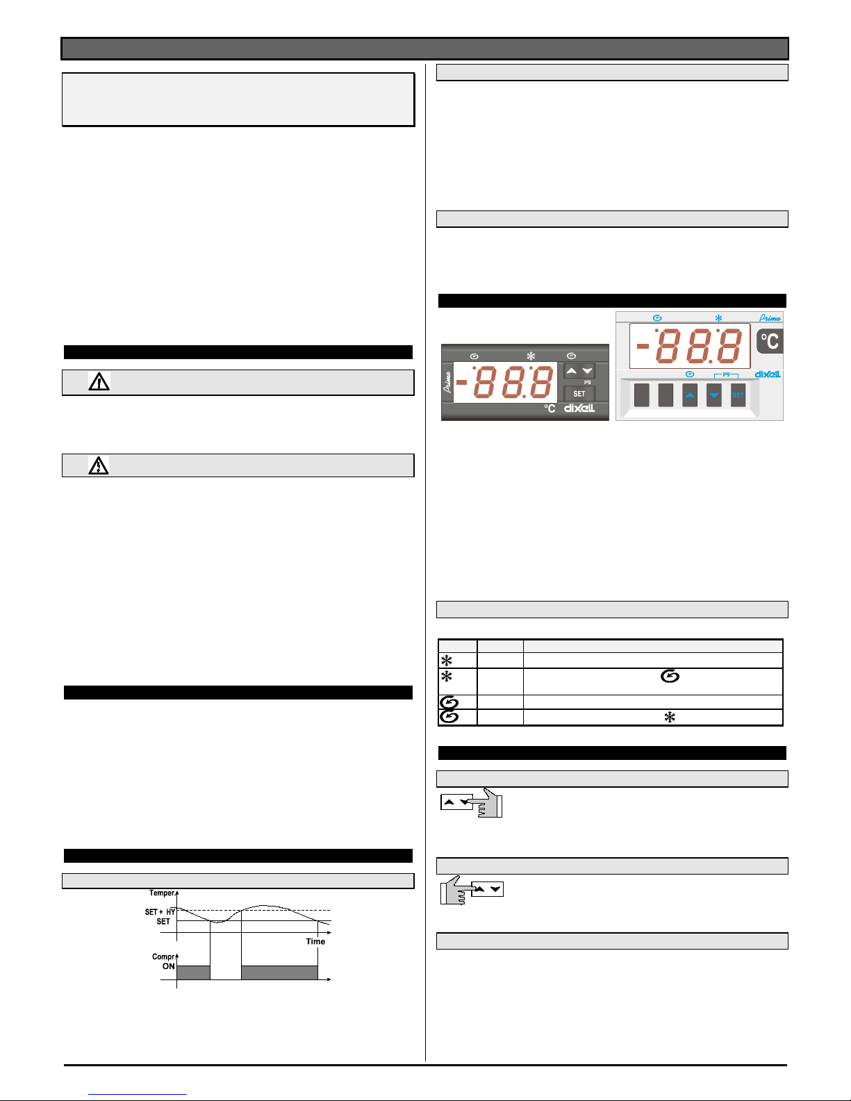
Models XR80C, 32x 74 format, and XR80D, DIN format, are a microprocessor based
controllers suitable for application in the milk preservation / refrigeration sector. They are
equipped with one thermostat probe and two relay outputs to control the compressor and
agitator.
The XR80C and XR80D allow a very accurate control of all the main functions required
during the "milk-tank preservation" cycles, including the timed cycles of agitator functions.
The operator can also manually start a timed agitation cycle by pushing the
o key on the
instrument's front panel.
Each instrument is fully configurable through special parameters that can be easily
programmed through the keypad.
3. CONTROLLING LOADS
3.1 THE COMPRESSOR
The regulation is performed according to the temperature measured by the thermostat
probe with a positive differential from the set point: if the temperature increases and
reaches set point plus differential the compressor is started and then turned off when the
temperature reaches the set point value again.
In case of fault in the thermostat probe the start and stop of the compressor are timed
through parameters “COn” and “COF”.
3.2 AGITATION CYCLE
The functions of the agitator can be selected by means of the AgC parameter.
AgC = EL (parallEL)the agitator always operates when the compressor is running and
continues to do so for a length of time - which can be set in parameter “Agt”
(Duration of agitation cycle)- even after the compressor stops. If the compressor does
not run longer than the time set in parameter “IAG” (Interval between agitation
cycles), the agitator will start to function anyway for the length of time set in parameter
Agt.
AgC= in independent agitator. The agitator is switched ON and OFF according to the IAg
parameter independently from the state of the compressor. It operates for the time set
in the Agt parameter.
3.3 MANUAL AGITATION CYCLE
It can be started by means of the o key, by holding it pressed for 3 seconds. Agitator
remains ON for the time set in Agt parameter. The compressor keeps with the normal
regulation.
4. FRONT PANEL COMMANDS
SET: To display target set point; in programming mode it selects a parameter or confirm
an operation.
o (UP): To see the max. stored temperature; in programming mode it browses the
parameter codes or increases the displayed value.
TO START A MANUAL AGITATION CYCLE: in normal operation, by holding it
pressed for 3s the agitation cycle is started.
n (DOWN) To see the min stored temperature; in programming mode it browses the
parameter codes or decreases the displayed value.
KEY COMBINATIONS:
o+ n To lock & unlock the keyboard.
SET + n To enter in programming mode.
SET + o To return to the room temperature display.
4.1 MEANING OF LEDS
Each LED function is described in the following table.
LED MODE FUNCTION
ON Compressor enabled
Flashing -Programming Phase (flashing with )
- Anti-short cycle delay enabled
ON Agitator enabled
Flashing
- Programming Phase (flashing with
)
5. MAXIMUM AND MINIMUM TEMPERATURE FUNCTIONS
5.1 HOW TO SEE THE MIN TEMPERATURE
1. Press and release the n key.
2. The “Lo” message will be displayed followed by the minimum
temperature recorded.
3. By pressing the n key again or by waiting 5s the normal display will be restored.
5.2 HOW TO SEE THE MAX TEMPERATURE
1. Press and release the o key.
2. The “Hi” message will be displayed followed by the maximum
temperature recorded.
3. By pressing the o key again or by waiting 5s the normal display will be restored.
5.3 HOW TO RESET THE MAX AND MIN TEMPERATURE RECORDED
1. Hold press the SET key for more than 3s, while the max. or min temperature is
displayed. (rSt message will be displayed)
2. To confirm the operation the “rSt” message starts blinking and the normal
temperature will be displayed.
XR80C signals and records temperature alarms, together with their duration and max
value reached. See drawing:
Page 2
dIXEL
Installing and Operating Instructions
R1.0 1592007271
1592007271 XR80C-D GB r1.0 20.05.2005.doc XR80C – XR80D 2/4
6. MAIN FUNCTIONS
6.1 HOW TO SEE THE SETPOINT
Push and immediately release the SET key: the display will show the
Set point value;
6.2 HOW TO CHANGE THE SETPOINT
1. Push the SET key for more than 2 seconds to change the Set
point value;
2. The value of the set point will be displayed and the
LED starts
blinking;
3. To change the Set value push the oor n arrows.
4. To memorise the new set point value push the SET key again or
wait 15s.
6.3 HOW TO START A MANUAL AGITATION CYCLE
6.4 HOW TO CHANGE A PARAMETER VALUE
To change the parameter’s value operate as follows:
1. Enter the Programming mode by pressing the Set and UP key for
3s (
and
start blinking).
2. Select the required parameter.
3. Press the “SET” key to display its value (
LED starts blinking).
4. Use “UP” or “DOWN” to change its value.
5. Press “SET” to store the new value and move to the following
parameter.
To exit: Press SET + UP or wait 15s without pressing a key.
NOTE: the set value is stored even when the procedure is exited by waiting the time-out to
expire.
6.5 THE HIDDEN MENU
The hidden menu Includes all the parameters of the instrument.
6.5.1 HOW TO ENTER THE HIDDEN MENU
1. Enter the Programming mode by pressing the Set + n key for 3s
(
and start blinking).
2. When a parameter is displayed keep pressed the Set+n for more
than 7s. The Pr2 label will be displayed immediately followed from the
HY parameter. NOW YOU ARE IN THE HIDDEN MENU.
3. Select the required parameter.
4. Press the “SET” key to display its value (Now only the
LED is
blinking).
5. Use oor n to change its value.
6. Press “SET” to store the new value and move to the following parameter.
To exit: Press SET + oor wait 15s without pressing a key.
NOTE: the set value is stored even when the procedure is exited by waiting the time-out to
expire.
6.5.2 HOW TO MOVE A PARAMETER FROM THE HIDDEN MENU TO
THE FIRST LEVEL AND VICEVERSA.
Each parameter present in the HIDDEN MENU can be removed or put into “THE FIRST
LEVEL” (user level) by pressing “SET + n”.
In HIDDEN MENU when a parameter is present in Fisrt Level the decimal point is on.
6.6 HOW TO LOCK THE KEYBOARD
1. Keep pressed for more than 3 s the UP and DOWN keys.
2. The “POF” message will be displayed and the keyboard will be locked. At this point it
will be possible only to see the set point or the MAX o Min temperature stored
3. If a key is pressed more than 3s the “POF” message will be displayed.
6.7 TO UNLOCK THE KEYBOARD
Keep pressed together for more than 3s the UP and DOWN keys.
7. LIST OF PARAMETERS
NOTE: the parameters preceded by dots usually are only in the Hidden Menu.
REGULATION
Hy Differential: (0,1 ÷ 25,5°C / 1÷255 °F) Intervention differential for set point.
Compressor Cut IN is Set Point Plus Differential (Hy). Compressor Cut OUT is when
the temperature reaches the set point.
• LS Minimum set point: (- 50°C÷SET / -58°F÷SET): Sets the minimum acceptable
value for the set point.
• US Maximum set point: (SET÷ 150°C / SET÷302°F). Set the maximum acceptable
value for set point.
Ot Thermostat probe calibration: (-12.0÷12.0°C;
-120÷120°F) allows the adjustment of possible offset of the thermostat probe.
• OdS Outputs activation delay at start up: (0÷255min) This function is enabled at
the initial start up of the instrument and inhibits any output activation for the period of
time set in the parameter.
AC Anti-short cycle delay: (0÷50 min) minimum interval between the compressor stop
and the following restart.
• COn Compressor ON time with faulty probe: (0÷255 min) time during which the
compressor is active in case of faulty thermostat probe. With COn=0 compressor is
always OFF.
• COF Compressor OFF time with faulty probe: (0÷255 min) time during which the
compressor is OFF in case of faulty thermostat probe. With COF=0 compressor is
always active.
DISPLAY
• CF Temperature measurement unit: °C = Celsius; °F= Fahrenheit. WARNING:
When the measurement unit is changed the SET point and the values of the
parameters Hy, LS, US, Ot, ALU and ALL have to be checked and modified if
necessary).
rES Resolution (for °C): (in = 1°C; dE = 0.1 °C) allows the decimal point displaying.
AGITATION CYCLE
• AgC Agitator configuration EL = switched ON and OFF with the compressor;
in = switched ON according to parameter IAg.
• tiC Resolution for the Agt parameter nP = the Agt parameter is in minutes
Pb = the Agt parameter is in seconds
iAG Interval between agitation cycles: (1÷120 min) Determines the time interval
between the beginning of two agitation cycles. NOTE: When a continuous agitation
cycle is started, the time counting is reset and starts from zero.
Agt Length for agitation cycle: (0÷255 min/sec) It sets the agitation cycle duration.
APO First agitation cycle after start-up: (y = Immediately; n= after the IAG time)
ALARMS
• ALC Temperature alarms configuration: (Ab; rE)
Ab= absolute temperature: alarm temperature is given by the ALL or ALU values. rE
= temperature alarms are referred to the set point. Temperature alarm is enabled
when the temperature exceeds the “SET+ALU” or “SET-ALL” values.
ALU MAXIMUM temperature alarm: (ALL÷150°C;
ALL ÷302°F) when this temperature is reached the alarm is enabled, after the “ALd”
delay time.
ALL Minimum temperature alarm: (-50.0°C ÷ ALU;
-58°F ÷ ALU) when this temperature is reached the alarm is enabled, after the “ALd”
delay time.
• ALd Temperature alarm delay: (0÷255 min) time interval between the detection of
an alarm condition and alarm signalling.
• dAO Exclusion of temperature alarm at startup: (from 0.0 min to 23.5h) time
interval between the detection of the temperature alarm condition after instrument
power on and alarm signalling.
OTHER
• PbC Probe selection: (Ptc=PTC probe; ntc=NTC probe). It allows the selection of
the type of probe.
• rEL Software release for internal use.
• Ptb Parameter table code: readable only.
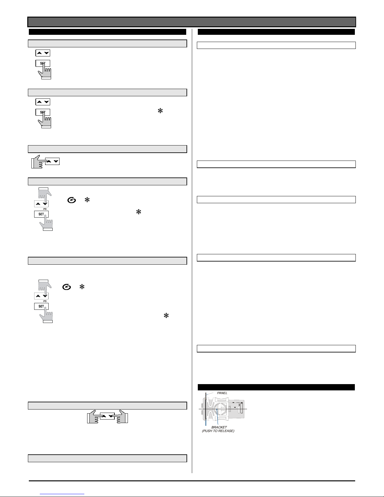
8. INSTALLATION AND MOUNTING
Instrument XR80C shall be mounted on panel, in a 29x71
mm hole, and fixed using the special bracket supplied.
To obtain an IP65 protection grade use the front panel
rubber gasket (mod. RG-C) as shown in figure.
Push the UP key for more than 2 seconds and a manual agitation
cycle will start.
Page 3

dIXEL
Installing and Operating Instructions
R1.0 1592007271
1592007271 XR80C-D GB r1.0 20.05.2005.doc XR80C – XR80D 3/4
Instrument XR80D shall be
mounted on a DIN rail.
The temperature range
allowed for correct operation
is 0÷60 °C. Avoid places
subject to strong vibrations,
corrosive gases, excessive
dirt or humidity. The same
recommendations apply to
probes. Let air circulate by the
cooling holes.
9. ELECTRICAL CONNECTIONS
The instrument is provided with screw terminal block to connect cables with a cross
section up to 2,5 mm
2
. Before connecting cables make sure the power supply complies
with the instrument’s requirements. Separate the probe cables from the power supply
cables, from the outputs and the power connections. Do not exceed the maximum current
allowed on each relay, in case of heavier loads use a suitable external relay.
9.1 PROBE CONNECTION
The probes shall be mounted with the bulb upwards to prevent damages due to casual
liquid infiltration.
10. HOW TO USE THE HOT KEY
10.1 HOW TO PROGRAM A HOT KEY FROM THE INSTRUMENT (UPLOAD)
1. Program one controller with the front keypad.
2. When the controller is ON, insert the “Hot key” and push o key; the "uPL"
message appears followed a by flashing “End”
3. Push “SET” key and the End will stop flashing.
4. Turn OFF the instrument remove the “Hot Key”, then turn it ON again.
NOTE: the “Err” message is displayed for failed programming. In this case push again o
key if you want to restart the upload again or remove the “Hot key” to abort the operation.
10.2 HOW TO PROGRAM AN INSTRUMENT USING A HOT KEY (DOWNLOAD)
1. Turn OFF the instrument.
2. Insert a programmed “Hot Key” into the 5 PIN receptacle and then turn the
Controller ON.
3. Automatically the parameter list of the “Hot Key” is downloaded into the Controller
memory, the “doL” message is blinking followed a by flashing “End”.
4. After 10 seconds the instrument will restart working with the new parameters.
5. Remove the “Hot Key”..
NOTE the message “Err” is displayed for failed programming. In this case turn the unit off
and then on if you want to restart the download again or remove the “Hot key” to abort the
operation.
11. ALARM SIGNALS
Message Cause Output
“EE” Data or memory failure
“P1” Probe failure Output according to par. “Con” and “COF”
“HA” Maximum temp. alarm Output unchanged.
“LA” Minimum temp. alarm Output unchanged.
11.1 ALARM “EE”
The instrument is provided with an internal check verifying memory integrity. Alarm “EE”
flashes when a failure in the internal memory is detected. In such case call the service.
11.2 ALARM RECOVERY
Probe alarm “P1” start some seconds after the fault in the related probe; it automatically
stops some seconds after the probe restarts normal operation. Check connections before
replacing the probe.
Temperature alarms “HA” and “LA” automatically stop as soon as the thermostat
temperature returns to normal values and when defrost starts.
12. TECHNICAL DATA
Housing: self extinguishing ABS.
Case: XR80C frontal 32x74 mm; depth 60mm;
XR80D 4 DIN modules 70x85 mm; depth 61mm
Mounting: XR80C panel mounting in a 71x29mm panel cut-out
XR80D DIN RAIL mounted in a omega (3) din rail
Protection: IP20;
Frontal protection: XR80C IP65 with frontal gasket RG-C (optional).
Connections: Screw terminal block ≤ 2,5 mm
2
wiring.
Power supply: according to the model: 12Vac/dc, ±10%; 24Vac/dc, ±10%; 230Vac
±10%, 50/60Hz, 110Vac ±10%, 50/60Hz
Power absorption: 3VA max
Display: 3 digits, red LED, 14,2 mm high; Inputs: 1 PTC or NTC probe.
Relay outputs: compressor SPST relay 8(3) A, 250Vac or SPST relay 20(8)A; 250Vac
agitator: SPDT relay 8(3) A, 250Vac or
Kind of action: 1B; Pollution grade: normal; Software class: A.
Data storing: on the non-volatile memory (EEPROM).
Operating temperature: 0÷60 °C; Storage temperature: -30÷85 °C.
Relative humidity: 20÷85% (no condensing)
Measuring and regulation range: PTC probe: -50÷150°C (-58÷302°F)
NTC probe: -40÷110°C (-58÷230°F)
Resolution: 0,1 °C or 1°C or 1 °F (selectable).
Accuracy (ambient temp. 25°C): ±0,7 °C ±1 digit
13. CONNECTIONS
13.1 XR80C: COMPRESSOR 8A
N.C.
12 34 5 6 7
91011 12
Comp
Thermost.
8
Hot Key
8(3)A250V 8(3)A250V
Line
12Vac/dc supply: connect to the terminals 7 and 8.
24Vac/dc supply: connect to the terminals 7 and 8.
120Vac supply: connect to the terminals 7 and 8.
13.2 XR80C: COMPRESSOR 20A
N.C.
12 34 5 6 7
91011 12
Comp
Thermost.
8
Hot Key
8(3)A250V 20(8)A250V
Line
12Vac/dc supply: connect to the terminals 7 and 8.
24Vac/dc supply: connect to the terminals 7 and 8.
120Vac supply: connect to the terminals 7 and 8.
13.3 XR80D: 8A COMPRESSOR
Power
Supply
230Vac
Line
8(3)A/250Vac
8(3)A/250 Vac
13 14 15 16 17 18 19
Comp
n.c.
11 12
3 4
n.c.
HOT KEY
24Vac/dc supply: connect to the terminals 11 and 12.
120Vac supply: connect to the terminals 11 and 12.
230Vac supply: connect to the terminals 11 and 12.
Page 4

dIXEL
Installing and Operating Instructions
R1.0 1592007271
1592007271 XR80C-D GB r1.0 20.05.2005.doc XR80C – XR80D 4/4
13.4 XR80D: 20A COMPRESSOR
Power
Supply
230Vac
11 12
3 4
Line
8(3)A/250Vac
20(8 )A/25 0Vac
15 16 17 18 19
Comp
n.c.
HOT KEY
24Vac/dc supply: connect to the terminals 11 and 12.
120Vac supply: connect to the terminals 11 and 12.
230Vac supply: connect to the terminals 11 and 12.
14. DEFAULT SETTING VALUES
Label Name Range Values
Set
Set point LS÷US 2.0
Hy
Differential
0,1÷25.5°C/ 1÷ 255°F
2.0
LS
Minimum set point
-50°C÷SET/-58°F÷SET
-30.0
US
Maximum set point
SET÷150°C/ SET ÷ 302°F
20.0
Ot
Thermostat probe calibration
-12÷ 12°C / -120 ÷ 120°F
0.0
OdS
Outputs delay at start up 0÷255 min 0
AC
Anti-short cycle delay
0 ÷ 50 min
1
COn
Compressor ON time with faulty probe
0 ÷ 255 min
15
COF
Compressor OFF time with faulty probe
0 ÷ 255 min
30
CF
Temperature measurement unit
°C ÷ °F
°C
rES
Resolution
in ÷ dE
dE
AgC
Agitator configuration EL=with compressor;
in=independent
EL
tIC
Resolution for the Agt parameter nP=minutes; Pb=seconds nP
IAg
Interval between agitation cycle 1÷120min 15
Agt
Length for agitation cycle 0÷255min 3
APO
First agitation cycle after start up y=immediately; n=after IAG n
ALc
Temperat. alarms configuration rE; Ab Ab
ALU
MAXIMUM temperature alarm
ALL÷150.0°C; ALL ÷302°F
100
ALL
Minimum temperature alarm
-50.0°C÷ALU/ -58°F ÷ ALU
-50.0
ALd
Temperature alarm delay
0 ÷ 255 min
15
dAo
Delay of temperature alarm at start up
0 ÷ 23h e 50’
1.3
PbC
Probe selection
Ptc ÷ ntc
ntc/Ptc
rEL
Software release -- 1.2
Ptb
Map code -- --
Hidden parameters
Dixell S.p.A. Z.I. Via dell’Industria, 27
32010 Pieve d’Alpago (BL) ITALY
tel. +39 - 0437 - 98 33 - fax +39 - 0437 - 98 93 13
E-mail: dixell@dixell.com - http://www.dixell.com
 Loading...