

dixell XLR130, XLR170, CoolMate XLR130C, CoolMate XLR170C Installing And Operating Insructions
Page 1
XLR130-170
Page 2

Page 3

1592017000 XLR 130-170 GB r2.0 23.03.2015 XL130 - XLR170 3/20
INDEX
1. GENERAL WARNING 4
2. GENERAL DESCRIPTION 4
3. CONTROLLING LOADS 4
4. KEYBOARD 6
5. REAL TIME CLOCK FUNCTION – ONLY FOR INSTRUMENTS WITH RTC 8
6. PARAMETER LIST 9
7. DIGITAL INPUTS 12
8. INSTALLATION AND MOUNTING 13
9. DIMENSIONS 15
10. ELECTRICAL CONNECTIONS 15
11. TTL SERIAL LINE 15
12. HOW TO USE THE HOT KEY 15
13. ALARM SIGNALS 16
14. TECHNICAL DATA 16
15. CONNECTIONS 17
16. DEFAULT SETTING VALUES 18
Page 4
1592017000 XLR 130-170 GB r2.0 23.03.2015 XL130 - XLR170 4/20
1. GENERAL WARNING
1.1 PLEASE READ BEFORE USING THIS MANUAL
• This manual is part of the product and should be kept near the instrument for easy and quick reference.
• The instrument shall not be used for purposes different from those described hereunder. It cannot be used as a safety device.
• Check the application limits before proceeding.
• Dixell Srl reserves the right to change the composition of its products, even without notice, ensuring the same and unchanged functionality.
1.2
SAFETY PRECAUTIONS
• Check the supply voltage is correct before connecting the instrument.
• Do not expose to water or moisture: use the controller only within the operating limits avoiding sudden temperature changes with high
atmospheric humidity to prevent formation of condensation
• Warning: disconnect all electrical connections before any kind of maintenance.
• Fit the probe where it is not accessible by the End User. The instrument must not be opened.
• In c as e of fai lure or faulty operat i on s end the instr um ent back to the distri butor or to “Dixell S.r.l.” (see address) with a detailed description of the
fault.
• Consider the maximum current which can be applied to each relay (see Technical Data).
• Ensure that the wires for probes, loads and the power supply are separated and far enough from each other, without crossing or intertwining.
• In case of applications in industrial environments, the use of mains filters (our mod. FT1) in parallel with inductive loads could be useful.
2. GENERAL DESCRIPTION
Models XLR130 and XLR170, 210x230mm format, are micr oprocessor based contr ollers suitabl e for applications on m edium or low temperatur e
refrigerati ng uni ts . T hey ar e pr ov i ded with four (XLR130) or s i x ( X LR170) relay outputs to contr ol c om pr es s or , defr os t - which can be ei ther electrical
or hot gas (XLR170) - the evaporator fans (X LR170), the l ights, the al arm and an auxi liary output . They are also pr ovided with thr ee NTC or PTC
probe inputs, one for tem perature cont rol, one to c ontrol the defr ost end temper ature of the evaporator and the third, optional, for the dis play . There
are two digital inputs (free contact) for the door switch and configurable by parameter.
The standard TTL output allows the user to c onnect , by m eans of a TTL/RS485 exter nal modul e, a ModBUS-RTU compatible monitoring system and
to programme the parameter list with the “Hot Key”.
Each model in t he XLR100 can be provided with a Real Tim e Clock which allows programming of up to eight dail y defrost cycles , divided into
holidays and workdays. A “Day and Night” function with two different set points is fitted for energy saving.
3. CONTROLLING LOADS
3.1 THE COMPRESSOR
The regulation is performed according to the tem perature measured by the therm ostat probe with a positiv e differential from the set point: if the
temperature inc reases and reaches s et point plus differ ential the compr essor is star ted and then turned off when the temperature reaches the set
point value again.
In case of fault in the thermostat probe the start and stop of the compressor are timed through parameters “COn” and “COF”.
3.2 FAST FREEZING
When defrost is not i n progress, it c an be activated the key pad by holding the o key pressed f or about 3 seconds. The com pressor operates i n
continuous mode for the tim e set thr ough the “CCt” param eter. T he cyc le c an be term inated befor e the end of the set ti m e us i ng t he s am e ac ti v ation
key,
o
for about 3 seconds.
3.3 DEFROST
3.3.1 XLR130 – TIMED DEFROST
The defrost interval is controlled by means of parameter “EdF”:
- with EdF=in the defrost is made every “IdF” time,
- with EdF=Sd the interval “IdF” is calculate through Smart Defrost algorithm (the counter is increased only when the compressor is ON).
- with real tim e c lock present E dF c an be s et to “rt c ”, In thi s c as e, t he defr os t i s m ade in real tim e depending on the hours set in the parameters
Ld1..Ld8 on workdays and in Sd1…Sd8 in holidays;
Defrost is performed through a simple stop of the compressor. Parameter “IdF” controls the interval between defrost cy cles, while its length i s
controlled by parameter “MdF”.
3.3.2 XLR170 – HEATER OR HOT GAS DEFROST
Three defrost modes are available through the “tdF” parameter: defrost with electrical heater (tdF=rE), hot gas (tdF=in), or therm ostatic defrost
(tdF=rt).
Page 5

1592017000 XLR 130-170 GB r2.0 23.03.2015 XL130 - XLR170 5/20
The defrost interval is controlled by means of parameter “EdF”:
- with EdF=in the defrost is made every “IdF” time,
- with EdF=Sd the interval “IdF” is calculate through Smart Defrost algorithm (the counter is increased only when the compressor is ON).
- with real tim e c lock present E dF c an be s et to “rt c ”. In thi s c as e, t he defr os t i s m ade in real tim e depending on the hours set in the parameters
Ld1..Ld8 on workdays and in Sd1…Sd8 in holidays;
At the end of defrost the drip time is controlled through the “Fdt” parameter.
3.4 CONTROL OF EVAPORATOR FANS (XLR170 OR XLR130 WITH OA1=FAN)
The fan control mode is selected by means of the “FnC” parameter:
C-n fans will switch ON and OFF with the compressor and not run during defrost;
C-y fans will switch ON and OFF with the compressor, also during defrost
After defrost, there is a timed fan delay allowing for drip time, set by means of the “Fnd” parameter.
O-n fans will run continuously and not run during defrost;
O-y fans will run continuously also during defrost
An additional par am eter “FS t” pr ov i des the s ett i ng of t em per atur e, detec t ed by the ev apor ator pr obe, abov e whi c h the f ans ar e al way s OF F. This can
be used to make sure circulation of air only if his temperature is lower than set in “FSt”.
3.5 AUXILIARY OUTPUT CONFIGURATION - TERM. 15-16, PAR. OA1
The functioning of the aux iliary relay (termi nals. 15-16) can be set by the oA1 paramet er, according to the kind of appl ication. In the followi ng
paragraph the possible setting:
3.5.1 XLR130: forced air application, normal temperature -oA1= Fan
Parameters involved:
- FnC Fan operating mode; - Fnd Fan delay after a defrost
- FSt Fan stop temperature; - FAP Probe for fan management
With this setting the auxiliary relay works as fan relay. See par. 3.4 “Control of evaporator fans”.
NOTE: if FAP = nP (no probe), the relay will be activated according to the setting of FnC parameter independently from the temperature of
evaporator.
3.5.2 Auxiliary relay - oA1= AUS
With oA1=AUS, two kinds of working are available.
A. The AUX relay is activated only by keyboard
Set oA1 =AUS and ArP= nP (no probe for auxiliary output).
In this case the relay 15-16 can be activated only by pushing the AUX button of the keyboard.
B. Auxiliary thermostat (I.E.. anti condensing hea te r) with the possi bil i ty of swi tc hing i t on a nd off also by keyboard
Parameters involved:
- ACH Kind of regulation for the auxiliary relay: heating /cooling;
- SAA Set point for auxiliary relay
- ArP Probe for auxiliary relay
By means of these 3 parameters the functioning of the auxiliary relay can be set.. The differential is given by the Hy parameter.
The auxiliary relay can be switched on also by the AUX button. In this case it remains on till it’s manually switched off.
The defrost doesn’t affect the status of auxiliary relay.
3.5.3 on/off relay - oA1 = onF
In this case the relay is activated when the controller is turned on and de-activated when the controller is turned off..
3.5.4 XLR170: Second defrost relay for applications with 2 evaporators – oA1 = dF2
Parameters involved:
- dtS end defrost temperature for second defrost relay;
- MdS maximum defrost duration for second defrost relay;
- dSP probe selection for second defrost
With 2 evaporators the regulation restarts when both the defrosts are finished.
3.5.5 Second compressor – oA1 = cP2
In this case the controller can manage 2 compressors or a 2 step compressor.
Functioning: the 2
nd
compressor is activ ated after the fist compr essor with a delay s et in the Ac1 parameter ( seconds). Both com pressor are
turned off at the same time.
If cco=AL compressors are switched on by turn.
Parameters involved:
- cco Compressor activation: type of sequence: by turn or in sequence;
- Ac1 Second compressor activation delay (seconds).
Page 6
1592017000 XLR 130-170 GB r2.0 23.03.2015 XL130 - XLR170 6/20
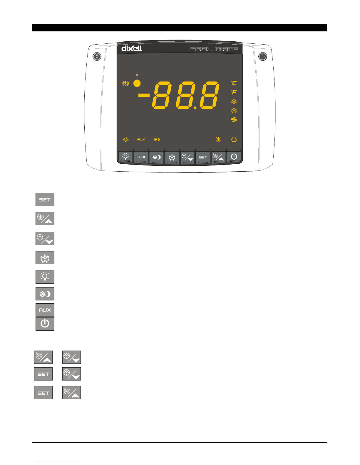
4. KEYBOARD
Panic LED
To display and modify target set point; in programming mode it selects a parameter or confirms an operation.
By holding it pressed for 3s when max or min temperature is displayed, it will be erased.
Only for models with RTC: by pressing it when the c urrent ti me is displayed, it all ows the User to re-set the cur rent ti me and thr ee
holidays.
To see the max. stored temper ature; in programmi ng mode it browses the param eter codes or increas es the displayed val ue. By
holding it pressed for 3s the fast freezing cycle is started.
To see the min stored temperature; in programming mode it browses the parameter codes or decreases the displayed value.
Only for models with RTC: by holding it pres s ed f or 3s the cur rent ti m e is display ed and it permits the Us er to ent er E ner gy s av
ing,
Defrost and Clock parameter menu.
By holding it pressed for 3s the defrost is started.
Only for models with RTC by pressing it when the current time is displayed, it allows the User to set defrost times.
Switch ON and OFF the cold room light.
To start and stop Energy Saving function.
Only for models with RTC: by holding it pressed for 6s, the holiday function is started or stopped.
By pressing it when the current time is displayed, it allows the User to set Energy Saving times.
If oA1 = AUS, it switches ON and OFF the auxiliary output.
To switch ON and OFF the instrument.
KEY COMBINATIONS
+
To lock and unlock the keyboard.
+
To enter the programming mode.
+
To exit the programming mode.
Page 7

1592017000 XLR 130-170 GB r2.0 23.03.2015 XL130 - XLR170 7/20
4.1 USE OF LEDS
Each LED function is described in the following table.
LED
MODE
Function
°C
ON
Celsius degrees display
°C
FLASHING
Programming phase
°F
ON
Fahrenheit degrees display
ON
The compressor is running
FLASHING
- Programming Phase (flashing with LED )
- Anti-short cycle delay enabled
ON
The fan is running
FLASHING
Programming Phase (flashing with LED )
ON
The defrost is enabled
FLASHING
Drip time in progress
ON
The Fast Freezing cycle is enabled
ON
- ALARM signal
- In “Pr2” indicates that the parameter is also present in “Pr1”
AUX
ON
Auxiliary output (15-16) on (oA1=AUS).
ON
Energy saving on
ON
Light on
ON
The instrument is off
4.2 4.2 HOW TO SEE THE MIN TEMPERATURE
1. Press and release the n key.
2. The “Lo” message will be displayed followed by the minimum temperature recorded.
3. By pressing the n key or waiting for 5s the normal display will be restored.
4.3 4.3 HOW TO SEE THE MAX TEMPERATURE
1. Press and release the o key.
2. The “Hi” message will be displayed followed by the maximum temperature recorded.
3. By pressing the o key or waiting for 5s the normal display will be restored.
4.4 4.4 HOW TO RESET THE MAX AND MIN TEMPERATURE RECORDED
To reset the stored temperature, when max or min temperature is displayed :
1. Press SET key until “rST” label starts blinking.
N.B. After the installation RESET the temperature stored .
4.5 HOW TO SEE AND MODIFY THE SET POINT
1. Push and immediately release the SET key: the display will show the Set point value;
2. The “°C” LED starts blinking;
3. To change the Set value push the o or n arrows within 10s.
4. To memorise the new set point value push the SET key again or wait 10s.
4.6 TO START A MANUAL DEFROST
Push the DEF key for more than 2 seconds and a manual defrost will start.
4.7 TO ENTER IN PARAMETERS LIST “PR1”
To enter the parameter list “Pr1” (user accessible parameters) operate as follows:
+
1. Enter the Programming mode by pressing the Set and DOWN key for few seconds (“°C” LED starts blinking).
2. The instrument will show the first parameter present in “Pr1”
Page 8

1592017000 XLR 130-170 GB r2.0 23.03.2015 XL130 - XLR170 8/20
4.8 TO ENTER IN PARAMETERS LIST “PR2”
To access parameters in “Pr2”:
1. Enter the “Pr1” level.
2. Select “Pr2” parameter and press the “SET” key.
3. The “PAS” flashing message is displayed, shortly followed by “0 - -” with a flashing zero.
4. Use o or n to input the security code in the flashing digit; confirm the figure by pressing “SET”.
The security code is “ 321“.
5. If the security code is correct the access to “Pr2” is enabled by pressing “SET” on the last digit.
Another possibility is the following: after switching ON the instrument the user can push Set and DOWN keys within 30 seconds.
NOTE: each parameter i n “P r 2” can be removed or put into “Pr1” (user level) by pressing “SET” + n. When a parameter is present in “Pr1” “decimal
point “ is on.
4.9 HOW TO CHANGE THE PARAMETER VALUE
1. Enter the Programming mode.
2. Select the required parameter with o or n.
3. Press the “SET” key to display its value (“°C” LED starts blinking).
4. Use o or n to change its value.
5. Press “SET” to store the new value and move to the following parameter.
To exit: Press SET + UP or wait 15s without pressing a key.
NOTE: the new programming is stored even when the procedure is exited by waiting the time-out.
4.10 HOW TO LOCK THE KEYBOARD
+
1. Keep the o and n keys pressed together for more than 3 s the o and n keys.
2. The “POF” mes s age wi l l be displayed and the keyboard is locked. At this point it is only possible the viewing of the set point or the
MAX o Min temperature stored and to switch ON and OFF the light and the auxiliary output.
TO UNLOCK THE KEYBOARD
Keep the o and n keys pressed together for more than 3s.
4.11 ON/OFF FUNCTION
By pushing the ON/OFF key, the instrument shows “OFF” for 5 sec. and the ON/OFF LED is switched ON.
During the OFF stat us , al l t he r el ay s are s w i tc hed O FF and the r egul ations are stopped; if a monitoring system is connected, it does not
record the instrument data and alarms.
N.B. During the OFF status the Light and AUX buttons are active.
4.12 TO SEE THE PROBE VALUES
1. Enter in “Pr1” level.
2. Select “dP1” parameter for probe 1, “dP2” parameter for probe 2, “dP3” parameter for probe 3, with
o
or n.
3. Press the “SET” key to see the value of the selected probe.
4. Press “ SET” to move to the following parameter.
5. REAL TIME CLOCK FUNCTION – ONLY FOR INSTRUMENTS WITH RTC
5.1 TO SEE THE CURRENT TIME AND DAY
1.
Push the n key for more than 3 seconds
2.
e
LED switches ON and the following messages are displayed:
Hur (hour); Min (Minute); dAY (day)
3. To exit push n key or wait 5 seconds
5.2 TO SET THE TIME AND THE WEEKLY HOLIDAYS
followe
d by
1. Push the n key for more than 3 seconds
2.
e
LED switches ON and the current time is displayed.
3. By pushing the SET k ey , t he
e
LED will s tar t f l as hi ng and s ett i ng the c ur r ent hour , minutes, day and the weekly holidays (up
to 3) will be possible.
4. To exit, press SET + UP or wait 15s without pressing any key.
Page 9

1592017000 XLR 130-170 GB r2.0 23.03.2015 XL130 - XLR170 9/20
5.3 TO SET THE DEFROST TIMES
followe
d by
1.
Push the n key for more than 3 seconds
2.
e
LED switches ON and the current time is displayed.
3. By pushing DEF key, the DEF led will start flashing and setting defrost time will be possible.
4. To exit, press SET + UP or wait 15s without pressing any key.
5.4 TO SET THE ENERGY SAVING TIMES
followe
d by
1. Push the n key for more than 3 seconds
2.
e
LED switches ON and the current time is displayed.
3. By pushing the ES key, the ES led will start flashing and setting Energy Saving time will be possible.
4. To exit, press SET + UP or wait 15s without pressing any key.
5.5 TO START HOLIDAY FUNCTION BY USING THE KEYBOARD
1.
Push the ES key for more than 6 seconds until the label “Hd” is shown.
2.
e
LED will start to blink slower than during time programming and the regulators will follow holiday times.
3. Push the ES key for more than 6 seconds to start normal functioning again.
6. PARAMETER LIST
REGULATION
Hy Differential: (0,1÷25,5°C; 1÷ 45°F) : Inter v ention differential for set point, always positive. Compressor Cut IN is Set Point Plus Differential (Hy).
Compressor Cut OUT is when the temperature reaches the set point.
LS Minimum set point limit: (-50,0°C÷SET; -58°F÷SET) Sets the minimum acceptable value for the set point.
US Maximum set point limit: (SET÷110°C; SET÷230°F) Set the maximum acceptable value for set point.
odS Outputs activat ion delay at start up: (0÷255 m in) This functi on is enabled at the initi al start up of the instr ument and inhibits any out put
activation for the period of time set in the parameter. (AUX and Light can work)
cco Compressors: kind of activation. Used only if oA1 =cP2: SE = sequential activation; AL = by turn activation
AC Anti-short cycle delay: (0÷30 min) interval between the compressor stop and the following restart.
Ac1 2
nd
compressor delay at start up (0÷255s) Time interval between the switching on of the first compressor and the second one. (0÷225s).
CCt Thermostat override: (0min ÷23h 50mi n) all ows to set the l ength of the conti nuous cyc le. Can be used, for instanc e, when the room i s fil led
with new products.
Con Compressor ON time with faulty probe: (0÷255 min) time dur ing which the compres sor is active in cas e of faul ty thermostat pr obe. With
COn=0 compressor is always OFF.
COF Compressor OFF time with faulty probe: (0÷255 min) time during whic h the compressor is of f in case of faulty therm ostat probe. With
COF=0 compressor is always active.
CH Type of action - Only for XLR130: CL = cooling; Ht = heating.
DISPLAY
CF Temperatu r e measu r emen t un it : °C = Celsius; °F = Fahrenheit . When the measurement unit is changed the SET point and the values of the
regulation parameters have to be modified
rES Resolution (for °C): (in = 1°C; de = 0,1°C) allows decimal point display. dE = 0,1°C; in = 1 °C
Lod Local display : select which probe is displayed by the instrument: P1 = Thermostat probe; P2 = Evaporator probe; P3 = auxiliary probe
1r2 = difference between P1 and P2 (P1-P2)
DEFROST
tdF Defr ost type Only f or XLR170: rE = el ectric al heater (Compr essor OFF) ; rT = thermos tat defros t. Duri ng the defrost t ime “MdF ”, the heater
switches On and OFF depending on the evaporator temperature and “dtE” value; in = hot gas (Compressor and defrost relays ON)
EdF Defrost mode:
rtc = Real T ime Clock mode. Defr ost ti me fol lows Ld1÷Ld8 parameters on work days and Sd1÷Sd8 on holiday s. Availab le only i f the ’ RTC
option is present
in = interval mode. The defrost starts when the time “Idf” is expired.
Sd = Smartfrost mode. The ti me IdF (i nterval between defrosts ) is i ncreased onl y when the com pressor is runni ng (even non c onsecutiv ely)
and only if the evaporator temperature is less than the value in "SdF” (set point for SMARTFROST).
SdF Set point for SMARTFROST: (-30
÷30 °C/ -22÷86 °F) evaporator tem perature which allows the IdF counting (interv al between defrosts) in
SMARTFROST mode.
dtE Defrost terminati on temperatu re Only for XLR170: (-50,0÷110,0°C; -58÷230°F) (Enabl ed only when the ev aporator probe i s present ) sets
the temperature measured by the evaporator probe which causes the end of defrost.
Page 10

1592017000 XLR 130-170 GB r2.0 23.03.2015 XL130 - XLR170 10/20
dtS Defrost termination temperature 2
nd
evaporator – Only for XLR170 if oA1=dF2 : (-50,0÷110,0°C; -58÷230°F) sets the temperature
measured by the 2nd evaporator probe which causes the end of defrost.
IdF Interval between defrosts: (1÷120h) Determines the time interval between the beginning of two defrost cycles.
MdF ( Maximum) dur ation of defrost: (0÷255 mi n) When P2P = n, no evaporator probe, i t sets the defrost duration, when P2P = y, defrost end
based on temperature, it sets the maximum length for defrost.
MdS (Maximum) duration of defrost for 2
nd
evaporator – Only f or X LR170 if oA1=dF2: (0÷255 mi n) It sets the max imum durati on of the def ros t
for 2nd evaporator.
dFd Display during defrost: rt = real temperature; it = temperature at the defrost start; Set = set point; dEF = “dEF” label; dEG = “dEG” label;
dAd Defrost display tim e out: (0
÷255 min) Sets the m aximum ti me between the end of defrost and the res tarting of the real r oom temperature
display.
dSd Start defrost delay - Only f or XLR170: ( 0÷99m in) This i s useful when different defrost start ti mes are necessar y to avoid overl oading the
plant.
Fdt Drain down time: (0÷60 min.) time interval between reaching defrost termination temperature and the restoring of the control’s normal
operation. This time allows the evaporator to eliminate water drops that might have formed due to defrost.
dPO First defrost after start-up:
y = Immediately; n = after the IdF time
dAF Defrost delay after fast freezing: (0min÷23h 50min) after a Fast Freezing cycle, the first defrost will be delayed for this time.
dFP End defrost probe for first evaporator selection – Only for XLR170: nP = no probe, defros t by time. Duration s et by M dF par am eter ; P 1 =
Probe 1 (thermostat probe); P2 = Probe 2 (evaporator probe); P3 = Probe 3 (display probe).
dSP E nd defrost pr obe for second evap orator selectio n – Only for XL R170: nP = no probe, defrost by time. Duration set by MdS parameter; P1
= Probe 1 (thermostat probe); P2 = Probe 2 (evaporator probe); P3 = Probe 3 (display probe).
FANS
FnC Fan operating mode: C-n = running with the compressor, OFF during the defrost;
C-y = running with the compressor, ON during the defrost;
O-n = continuous mode, OFF during the defrost;
O-y = continuous mode, ON during the defrost;
Fnd Fan delay after defrost: (0÷255 min) The time interval between the defrost end and evaporator fans start.
FSt Fan stop temperature: (-50÷110°C; -58÷230°F) setting of temperature, detected by evaporator probe, above which the fan is always OFF.
FAP Fan probe selection: nP = no probe, fans ac t ac c or di ng t o the Fnc parameter, without temperature control set in FSt parameter; P1 = Probe 1
(Thermostat probe); P2 = Probe 2 (evaporator probe); P3 = Probe 3 (display probe).
ALARMS
ALC Temperature alarm configuration: rE = High and Low alarms related to Set Point;
Ab = High and low alarms related to the absolute temperature.
ALU High temperature alarm setting: ( ALC= rE, 0 ÷ 50°C or 90°F; ALC= Ab, ALL ÷ 110°C or 230°F)
when this temperature is reached and after the ALd delay time the HA alarm is enabled.
ALL Low temperature alarm setting: ( ALC = rE , 0 ÷ 50 °C or 90°F; ALC = Ab , - 50°C or -58°F ÷ ALU)
when this temperature is reached and after the ALd delay time, the LA alarm is enabled,.
AFH T emperat ur e alarm an d fan d iffer ent ial: ( 0,1÷25,5°C; 1÷ 45°F) Interv ention di fferenti al for tem perature al arm set poi nt and fan regulation set
point, always positive.
ALd Temperature alarm delay: (0÷255 min) time interval between the detection of an alarm condition and the corresponding alarm signalling.
dAO Delay of temperature alarm at start-up: (0min÷23h 50min) time interval between the detection of the temperature alarm condition after the
instrument power on and the alarm signalling.
EdA Alarm delay at the end of defr ost: (0
÷255 min) Tim e interval between the detecti on of the temperat ure alarm conditi on at the end of defrost
and the alarm signalling.
dot Delay of temperature alarm after closing the door : (0
÷255 min) Time delay to signal the temperature alarm condition after closing the door.
doA Open door alarm d elay:(0÷254m in,nu) delay between the detec tion of the open door condi tion and i ts alarm si gnall ing: the flas hing m essage
“dA” is displayed. If doA=nu the door alarm will be not signalled.
rrd Output restart after door open alarm doA: no = outputs unchanged after doA alarm; yES = outputs restart after doA alarm;
tbA Buzzer and alarm relay silencing: by pushing one of the keypad buttons.
n= Only the Buzzer is silenced; y= Buzzer and relay are silenced.
nPS Pressure switch numb er : (0
÷15) Number of activation of the pressure switch, during the “did” interval, before signalling the alarm event (I2F=
PAL).
PROBE INPUTS
Ot The rmos tat probe calibration: (-12.0÷12.0°C/ -21÷21°F) allows to adjust possible offset of the thermostat probe.
OE Evaporator probe calibration – Only for XLR170: (-12.0÷12.0°C/ -21÷21°F) allows to adjust possible offsets of the evaporator probe.
O3 Auxiliary probe calibration: (-12.0÷12.0°C/ -21÷21°F) allows to adjust possible offsets of the evaporator probe.
P2P Evaporator probe presence - Only for XLR170:
n= not present: the defrost stops only by time; y= present: the defrost stops by temperature and time.
P3P Auxiliary probe presence (display): n= not present; y= present.
Pbr Thermostat probe selection P1 = Probe 1 (Thermostat probe); P2 = Probe 2 (evaporator probe); P3 = Probe 3 (display probe); 1r2 = P1-P2.
HES T emperat ur e increase d uri ng th e Ener gy Savi ng cycle : (-30÷30°C / -54÷54°F) s ets the i nc r eas i ng v al ue of the s et point during the Energy
Saving cycle.
Page 11

1592017000 XLR 130-170 GB r2.0 23.03.2015 XL130 - XLR170 11/20
DIGITAL INPUTS
odc Com pres sor and fan status when open door:
no = normal; Fan = Fan OFF; CPr = Compressor OFF; F_C = Compressor and fan OFF.
I1P Door switch input polarity: CL : the digital input is activated by closing the contact; OP : the digital input is activated by opening the contact.
I2P Configurable digital input polarity: CL : the digital input is activated by closing the contact;
OP : the digital input is activated by opening the contact
I2F Digital input operating mode: configure the digital input function: EAL = generic al arm; bAL = seri ous alar m mode; PAL = Pressure switch;
dFr = Start defrost; AUS = Relay AUX actuation; Es = Energy Saving; onF = remote On/OFF; HdF = Holiday function.
did Time interval/delay for digital input alarm:(0
÷255 min.) Time interval to calculate the number of the pressure switch activation when
I2F=PAL. If I2F=EAL or bAL (ex ternal alar ms), “did” param eter defines the ti me delay between the detecti on and the successive signal ling of
the alarm.
AUXILIARY RELAY CONFIGURATION
oA1 Auxiliary rel ay configur ation ( terminal s 15-16): dEF = Not set it; ALr = al arm; FAn = fans; Lig =light; AUS = auxil i ary; onF = on/off; dF2 =
second defrost (only for XLR170), cP2 = second compressor (only for XLR170).
AUXILIARY THERMOSTAT CONFIGURATION (terms. 15-16) – OA1 = AUS
ACH Kind of regulation for auxiliary relay: Ht = heating; CL = cooling
SAA Set Point for auxiliary relay: (-50,0÷110,0°C; -58÷230°F) it defines the room temperature setpoint to switch auxiliary relay.
ArP Probe selection for auxil iary: nP = no probe, the auxi liary relay is swi tched only by button; P1 = Probe 1 (T hermostat probe); P2 = Probe 2
(evaporator probe); P3 = Probe 3 (display probe).
AoP Alarm relay polarity (terms. 29-30-31): oP = 29-30 terminals open with alarm; cL = 29-30 terminals close with alarm
TO SET CURRENT TIME AND WEEKLY HOLIDAYS (
3SEC followed by ) – Only for models with RTC
Hur Current hour (0 ÷ 23 h)
Min Current minute (0 ÷ 59min)
dAY Current day (Sun ÷ SAt)
Hd1 First weekly holiday (Sun ÷ nu) Set the first day of the week which follows the holiday times.
Hd2 Second weekly holiday (Sun ÷ nu) Set the second day of the week which follows the holiday times.
Hd3 Third weekly holiday (Sun ÷ nu) Set the third day of the week which follows the holiday times.
N.B. Hd1,Hd2,Hd3 can be set also as “nu” value (Not Used).
TO SET ENERGY SAVING TIMES (3SEC.
afterward )
ILE Energy Saving cycl e start du ring w orkdays: (0 ÷ 23h 50 mi n.) Duri ng t he Energy Savi ng cy cl e the set poi nt is inc reas ed by the val ue in
HES so that the operation set point is SET + HES.
dLE Energy Saving cycle length during workdays: (0 ÷ 24h 00 min.) Sets the duration of the Energy Saving cycle on workdays.
ISE Energy Saving cycle start on holidays. (0 ÷ 23h 50 min.)
dSE Energy Saving cycle length on holidays (0 ÷ 24h 00 min.)
HES T emperatur e increase d uring t he Ener gy Saving cycle (-30÷30°C / -54÷54°F) s ets the inc reasing v alue of the set point during the Energy
Saving cycle.
TO SET DEFROST TI MES (3SEC.
afterward )
Ld1÷Ld8 Wor kday defr ost st art (0 ÷ 23h 50 min.) These par ameters set t he beginni ng of the eight progr amm able defrost cy cl es during workday s.
Ex. When Ld2 = 12.4 the second defrost starts at 12.40 during workdays.
Sd1÷Sd8 Holid ay defrost st art (0 ÷ 23h 50 min.) T hese parameters set the beginning of the ei ght programm able defrost cyc les on holidays. Ex .
When Sd2 = 3.4 the second defrost starts at 3.40 on holidays.
N.B. :To disable a defrost cycle set it to “nu”(not used). Ex. If Ld6=nu ; the sixth defrost cycle is disabled
OTHER
Adr RS485 serial address (1÷247): Identifies the instrument address when connected to a ModBUS compatible monitoring system.
PbC Probe selection: (Ptc=PTC probe; ntc=NTC probe). It allows to select the kind of probe.
Rel Release software: (read only) Software version of the microprocessor.
Ptb Parameter table: (read only) it shows the original code of the dIXEL parameter map.
dP1 Probe 1 temperature (thermostat): it displays the temperature detected by the thermostat probe.
dP2 Probe 2 temperature (evaporator): it displays the temperature detected by the evaporator probe.
dP3 Probe 3 temperature (display): it displays the temperature detected by the display probe.
Pr2 Access to the protected parameter list (read only).
Page 12

1592017000 XLR 130-170 GB r2.0 23.03.2015 XL130 - XLR170 12/20
7. DIGITAL INPUTS
The Wing series can support up to 2 free contact digital inputs. One is always configured as door switch, the second is programmable in seven
different configurations by the “I2F” parameter.
7.1 DOOR SWITCH INPUT
It signals the door status and the corresponding relay output status through the “odc” parameter:
no = normal (any change);
Fan = Fan OFF;
CPr = Compressor OFF;
F_C = Compressor and fan OFF.
Since the door i s opened, after the del ay tim e set through par ameter “dOA”, the al arm output i s enabled and the di splay s hows the mes sage “dA”.
The alarm stops as soon as the ex ternal di gital i nput is di sabled agai n. During thi s tim e and then for the del ay “dot” after cl osi ng the door, t he high
and low temperature alarms are disabled.
7.2 CONFIGURABLE INPUT - GENERIC ALARM (EAL)
As soon as the digi tal input is ac tivated the unit wi ll wait for “did” time del ay before si gnalling the “EAL” al arm mess age. The outputs status don’t
change. The alarm stops just after the digital input is de-activated.
7.3 CONFIGURABLE INPUT - PANIC ALARM (i2F = PAn)
As soon as the digi tal i nput is act ivated the uni t displ ays the “PAn” alarm m ess age, the alar m buz zer, relay and panic LED ar e acti vated. The ot her
outputs status don’t change. The alarm stops just after the digital input is de-activated.
7.4 CONFIGURABLE INPUT - SERIOUS ALARM MODE (BAL)
When the digital input i s ac tiv ated, the uni t wil l w ait for “did” delay befor e si gnall ing the “BAL” al arm m ess age. The rel ay output s are s witc hed OFF .
The alarm will stop as soon as the digital input is de-activated.
7.5 CONFIGURABLE INPUT - PRESSURE SWITCH (PAL)
If during the interv al time set by “did” parameter , the pressure switch has reached the number of activati on of the “nPS” parameter, the “PAL”
pressure alar m mess age will be displ ayed. The compres sor and the regul ation are s topped. When the digi tal i nput is ON the c ompres sor is always
OFF.
7.6 CONFIGURABLE INPUT - START DEFROST (DFR)
It executes a defros t if there ar e the right c onditions . After the defrost is finished, the normal regulation wi ll restar t only if the digi tal i nput is dis abled
otherwise the instrument will wait until the “Mdf” safety time is expired.
7.7 CONFIGURABLE INPUT - RELAY AUX ACTUATION (AUS)
This function allows to turn ON and OFF the auxiliary relay by using the digital input as external switch.
7.8 CONFIGURABLE INPUT - ENERGY SAVING (ES)
The Energy Savi ng function al lows t o change the set poi nt value as t he result of the SET+ HES (par ameter) s um. Thi s functi on is enabled unti l the
digital input is activated.
7.9 CONFIGURABLE INPUT - REMOTE ON/OFF (ONF)
This function allows to switch ON and OFF the instrument.
7.10 CONFIGURABLE INPUT - HOLIDAY FUNCTION (HDF)
In Holiday function Energy saving and defrost cycles follow holiday times. (Sd1…Sd8)
7.11 DIGITAL INPUTS POLARITY
The digital inputs polarity depends on “I1P” and “I2P” parameters.
CL : the digital input is activated by closing the contact, OP : the digital input is activated by opening the contact
Page 13

1592017000 XLR 130-170 GB r2.0 23.03.2015 XL130 - XLR170 13/20
8. INSTALLATION AND MOUNTING
The temperature range al lowed for correct operation is 0 - 60 °C. Avoid plac es subject to strong vibrat ions, corrosive gases, excessive dirt or
humidity. The same recommendations apply to probes. Let the air circulate by the cooling holes.
Thanks to the case, XLR130 and XLR170 models can be panel or wall mounted. See the following instructions for details.
A
B
C
D E
GF
FIG. 1
A
B
C
G
F
D
FIG. 2
87
230
M
A
X
3
7
210
130
120
M
A
X
2
8
H
I
FIG. 3
Page 14

1592017000 XLR 130-170 GB r2.0 23.03.2015 XL130 - XLR170 14/20
A
Fig. 6
200
61
0
0 172
1
0
6
.
4
4
°
19018
Fig. 4
2
00
192.5
185
61
12
6
0
0
4
11
14.5
22.5
29.5
160.55
167.5
175.5
179
186
190
R
5
8.5
8
.
5
1
0
6
.
4
4
°
R
5
Fig. 5
8.1 WALL MOUNTING
1. Unscrew the 4 frontal screws (Fig. 1, A, B, F, G) and remove the cover (Fig. 1, C).
2. Unscrew the 2 screws (Fig. 1, D, E) that keep connected the frontal and lower parts of Cool Mate and separate the 2 parts.
3. M ake the proper holes for cablepres ses or pipepres ses using t he centres si gned in the bottom cover of the Cool Mate, (Fig. 3, H, I, ) . Then
make 3 holes in the wall, as indicated in (Fig. 3, L, M, N), to fix the Cool Mate
4. Fix the cablepresses and the pipepresses..
5. Ins ert the wal l-nugs, contained i n t he k i t, i nto the holes made in the wal l . Then us e the o-rings and fix the back part of the Cool Mate (Fig. 3, L,
M, N) by means of the 3 screws to the wall itself.
6. Insert the wiring cables in cablepresses or in the pipepresses.
7. Mount the frontal part using the previous 4 screws Fig. 1, D, E, F, G. (do not press excessively in order to avoid plastic deformation).
8. After connecting the wires to the terminal blocks close the cover (Fig. 2, c) and fix it by the screws.
Page 15

1592017000 XLR 130-170 GB r2.0 23.03.2015 XL130 - XLR170 15/20
8.2 PANEL MOUNTING
1. Make a hole in the panel with dimensions described in Fig. 4 (simplified) or Fig. 5 (completed)
2. Unscrew the 4 frontal screws (Fig. 1, A, B, F, G) and remove the cover (Fig. 1, C).
3. Unscrew the 2 screws (Fig. 1, D, E) that keep connected the frontal and lower parts of Cool Mate and separate the 2 parts.
4. Cut from the back part of the Cool Mate the teeth indicated in Fig. 6, A.
5. Make the proper holes for cablepresses or pipepresses using the centres signed in the bottom cover of the Cool Mate, (Fig. 3, H, I, ).
6. Fix the cablepresses and the pipepresses..
7. Insert the wiring cables in cablepresses or in the pipepresses.
8. Joi n the back and frontal parts, with the panel in the mi ddle, and fix t hem screwi ng the 4 screws tak en previousl y away (dim ensions 4x 35
mm), in the holes of Fig. 1, A, B, D, E. Maximum panel thickness: 6mm.
9. After connecting the wires to the terminal blocks close the cover (Fig. 2, c) and fix it by the screws.
9. DIMENSIONS
210 87
230
10. ELECTRICAL CONNECTIONS
The instruments ar e pr ov i ded wi t h s c rew ter m i nal block to connect c abl es w i th a c r os s s ec ti on up to 2, 5 m m2. Heat-resistant cables have to be used.
Before connecting c ables make sure the power suppl y complies with the ins trument’s requirements . Separate the probe cables from the power
supply cables , f r om the output s and the power c onnec ti ons . D o not ex c eed the m ax i mum current al lowed on each relay, in case of heavier l oads use
a suitable external relay.
10.1 PROBE CONNECTIONS
The probes s hall be m ounted with the bulb upwards to prevent dam ages due to casual liqui d infil trati on. It is r ecommended t o place the ther mostat
probe away from air stream s to corr ectly measure the av erage room t emperature. P lace the defr ost term ination pr obe among the evaporator fins in
the coldest place, where most ice is formed, far from heaters or from the warmest place during defrost, to prevent premature defrost termination.
11. TTL SERIAL LINE
Instruments of CoolMate series are provided with serial communication port that can be TTL or RS485 (optional).
The TTL connector allows, by means of the external module TTL/RS485, to connect the unit to a network line ModBUS-RTU compatible as the Dixell
monitoring system XJ500 l’XWEB3000, o l’XWEB300 (Dixell).
The same TTL connect or is us ed to upload and download the param eter l is t of the “HOT KE Y“. These i nstr uments can be or dered wi th dir ect ser ial
output RS485 (Optional).
12. HOW TO USE THE HOT KEY
12.1 HOW TO PROGRAM A HOT KEY FROM THE INSTRUMENT (UPLOAD)
1. Program one controller with the front keypad.
2. When the controller is ON, insert the “Hot key” and push o key; the "uPL" message appears followed a by flashing “End”
3. Push “SET” key and the End will stop flashing.
4. Turn OFF the instrument remove the “Hot Key”, then turn it ON again.
NOTE: the “Err” mes sage is di splay ed for fail ed programm ing. In this case push again o key if you want to r estar t the upload agai n or r emove t he
“Hot key” to abort the operation.
Page 16

1592017000 XLR 130-170 GB r2.0 23.03.2015 XL130 - XLR170 16/20
12.2 HOW TO PROGRAM AN INSTRUMENT USING A HOT KEY (DOWNLOAD)
1. Turn OFF the instrument.
2. Insert a programmed “Hot Key” into the 5 PIN receptacle and then turn the Controller ON.
3. Aut omatically the par ameter list of the “ Hot Key” is downl oaded into the Controller m emory, the “doL” message is bli nking followed a by
flashing “End”.
4. After 10 seconds the instrument will restart working with the new parameters.
5. Remove the “Hot Key”..
NOTE t he message “Err” i s displ ayed for fai led progr amming. In this c ase turn the uni t off and then on if y ou want to restar t the download again or
remove the “Hot key” to abort the operation.
13. ALARM SIGNALS
Message
Cause
Outputs
“P1”
Thermostat probe failure
Alarm output ON; Compressor output according to parameters “COn” and “COF”
“P2”
Evaporator probe failure
Alarm output ON; Other outputs unchanged
“P3”
Auxiliary probe failure
Alarm output ON;
Other outputs unchanged
“HA”
Max. temperature alarm
Alarm output ON; Other outputs unchanged
“LA”
Min. temperature alarm
Alarm output ON; Other outputs unchanged
“EE”
Data or memory failure
Alarm output ON; Other outputs unchanged
“dA”
Door switch alarm
Alarm output ON; Other outputs unchanged
“EAL”
External alarm
Alarm output ON; Other outputs unchanged
“BAL”
Serious external alarm
Alarm output ON; Other outputs OFF
“PAL”
Pressure switch alarm
Alarm output ON; Other outputs OFF
PAn
“Panic” Alarm
Alarm output ON; Other outputs unchanged
“rtc”
Real time clock alarm
Alarm output ON; Other outputs unchanged; Defrosts according to par. “IdF”
The alarm message is displayed until the alarm condition is recovery.
All the alarm messages are showed alternating with the room temperature except for the “P1” which is flashing.
To reset the “EE” alarm and restart the normal functioning press any key, the “rSt” message is displayed for about 3s.
13.1 SILENCING BUZZER / ALARM RELAY OUTPUT
If “tbA = y”, once the alarm signal is detected the buzzer and the relay are is silenced by pressing any key.
If “tbA = n”, only the buzzer is silenced while the alarm relay is on until the alarm condition recovers.
13.2 “EE” ALARM
The dIXEL i nstrument s are provi ded with an i nternal chec k for the data i ntegrit y. Alar m “EE” fl ashes when a fai lure in the memory data occurs. In
such cases the alarm output is enabled.
13.3 ALARM RECOVERY
Probe alarms : “P1” (probe1 faulty) , “P2” and “P3”; they automaticall y stop 10s after the probe r estarts nor mal oper ation. Check connecti ons before
replacing the probe.
Temperature alarms “HA” and “LA” automatically stop as soon as the thermostat temperature returns to normal values or when the defrost starts.
Door switch alarm “dA” stop as soon as the door is closed.
External alarms “EAL”, “BAL” stop as soon as the external digital input is disabled “PAL” alarm is recovered by switching OFF the instrument.
14. TECHNICAL DATA
Housing: self extinguishing ABS; Case: frontal 210x230 mm; depth 87mm; Mounting: See par. 9; Protection: IP65
Connections: Screw terminal block ≤ 2,5 mm
2
wiring.
Power supply: 230Vac 50/60Hz
± 10% or 110Vac 50/60Hz ± 10%; Power absorption: 10VA max.
Display:3 digits, red LED, 30.5 mm high.
Inputs: 3 NTC or PTC probes
Digital inputs : doorswitch and configurab le, free voltage. M ax. distance 10m
Relay outputs:
compressor: relay SPST 20(8) A, 250Vac
light: relay SPST 16(3) A, 250Vac
fans: relay SPST 8(3) A, 250Vac
defrost: relay SPDT 16(3) A, 250Vac
alarm: SPDT relay 8(3) A, 250Vac
auxiliary: SPST relay 20(8) A, 250Vac
Other output :
Alarm buzzer (Standard)
Direct RS485 (optional)
Page 17

1592017000 XLR 130-170 GB r2.0 23.03.2015 XL130 - XLR170 17/20
Serial output : TTL standard
Communication protocol: Modbus - RTU
Data storing: on the non-volatile memory (EEPROM).
Internal clock back-up: 24 hours
Kind of action: 1B; Pollution grade: normal; Software class: A.
Operating temperature: 0÷60 °C.
Storage temperature: -25÷60 °C.
Relative humidity: 20
÷85% (no condensing)
Measuring and regulation range: NTC probe: -40÷110°C (-58÷230°F)
Resolution: 0,1 °C or 1°C or 1 °F (selectable).
Accuracy (ambient temp. 25°C): ±0,5 °C ±1 digit
15. CONNECTIONS
15.1 XLR130
15.1.1 FREE VOLTAGE CONTACTS
1 2 3 4 5 6 7 8 9 1011 12 13 14 15 16 17 18 19 20 21 22 2 3 24 25 26 27 28 29 30 31 32 33 34
Light
16A
250V~
20A 250V
16FLA(96LRA)
20A 250V
16FLA(96LRA)
8A
250V~
N
Alarm
NC
35 36
RS 485
optional
Comp
15.1.2 DIRECT LOAD CONNECTIONS
15.2 XLR170
15.2.1 FREE VOLTAGE CONTACTS
1 2 3 4 5 6 7 8 9 1011 12 13 14 15
16 17 18 19 20 21 22 23 24 25 26 27 28 29 30 31 32 33 34
Light
16A
250V~
16A
250V~8A250V~
20A 250V
16FLA(96LRA)
20A 250V
16FLA(96LRA)
8A
250V
~
N
Comp
Line
Def.
NC
Alarm
NC
Fan
35 36
RS 485
optional
15.2.2 DIRECT LOAD CONNECTIONS
Page 18

1592017000 XLR 130-170 GB r2.0 23.03.2015 XL130 - XLR170 18/20
16. DEFAULT SETTING VALUES
Label
Name
Range
XLR130
XLR170
Level
REGULATION
Set
Set point
LS÷US
3.0
-5.0
---
Hy
Differential
0,1÷25,5 °C / 1÷45°F
2.0
2.0
Pr1
LS
Minimum set point
-50,0°C÷SET / -58°F÷SET
-10.0
-30,0
Pr2
US
Maximum set point
SET ÷ 110°C / SET ÷ 230°F
20.0
20.0
Pr2
OdS
Outputs acti v ation delay at start up
0÷255 min.
0 0 Pr2
cco
Compressor configurati on
SE; AL
SE
SE
Pr2
AC
Anti-short cycle delay
0÷30 min.
1 1 Pr1
Ac1
Second compressor start up delay
0÷255 sec.
0 0 Pr2
CCt
Compressor ON tim e duri ng fast freezing
0 ÷ 23h 50 min.
0.0
0.0
Pr2
COn
Compressor ON tim e w ith faulty probe
0÷255 min.
15
15
Pr2
COF
Compressor OFF t im e w i th faulty probe
0÷255 min.
30
30
Pr2
CH
Kind of action
CL; Ht
cL
- - -
Pr2
DISPLAY
CF
Temperature measurement unit
°C ÷ °F
°C
°C
Pr2
rES
Resolution (integer/dec i m al poi nt)
in ÷ de
dE
dE
Pr1
Lod
Local display
P1 ÷ 1r2
P1
P1
Pr2
DEFROST
tdF
Defrost type
rE, rT, in
- - -
rE
Pr2
EdF
Defrost mode
rtc, In, Sd
in
in
Pr2
SdF
Set point for SMART DEFROST
-30 ÷ +30°C / -22÷+86°F
0 0 Pr2
dtE
Defrost terminat i on temperature (1°Evaporator)
-50,0÷110°C /-58÷230°F
8.0
8.0
Pr2
dtS
Defrost termination temperature (2°Ev aporator)
-50,0÷110°C / -58÷230°F
- - -
8.0
Pr2
IdF
Interval between defrost cycles
1÷120h
8 8 Pr1
MdF
(Maximum) length for 1° def rost
0÷255 min.
20
20
Pr1
MdS
Maximum) length for 2° defr os t.
0÷255 min.
- 0 Pr2
dFd
Displaying during defrost
rt, it, SEt, dEF, dEG
it
it
Pr2
dAd
MAX display delay after defrost
0÷255 min.
30
30
Pr2
dSd
Start defrost delay
0÷99 min.
- - - 0 Pr2
Fdt
Draining time
0÷60 min.
- - - 0 Pr2
dPO
First defrost after start up
n ÷ y
n n Pr2
dAF
Defrost delay after fast freezing
0 ÷ 23h 50 min.
2
2.0
Pr2
dFP
End defrost probe for firs t evaporator
nP; P1, P2, P3
- - -
P2
Pr2
dSP
End defrost probe for second ev apor ator
nP; P1, P2, P3
- - -
nP
Pr2
FANS
FnC
Fans operating mode
C-n, C-y, O-n, O-y
O-n
O-n
Pr2
Fnd
Fans delay after defrost
0÷255 min.
10
10
Pr2
FSt
Fans stop temperature
-50,0÷110°C / -58÷230°F
2.0
2.0
Pr2
FAP
Fan probe selection
nP; P1, P2, P3
nP
P2
Pr2
ALARMS
ALC
Temperature alarms confi guration
rE÷Ab
rE
rE
Pr2
ALU
MAXIMUM temperature alarm
-50,0÷110°C/-58÷230°F
10.0
10.0
Pr1
ALL
minimum temperature alarm
-50,0÷110°C/ -58÷230°F
10.0
10.0
Pr1
AFH
Temperature alarm and fan differential
0,1÷25,5 °C/ 1÷45°F
2.0
2.0
Pr2
ALd
Temperature alarm delay
0÷255 min.
15
15
Pr2
dAO
Delay of temperature alarm at start up
0 ÷ 23h 50 min.
1.3
1.3
Pr2
EdA
Alarm delay at the end of defrost
0÷255 min.
30
30
Pr2
dot
Delay of temperature alarm after closing the door
0÷255 min.
15
15
Pr2
dOA
Open door alarm delay
0÷254 min.,nu
15
15
Pr2
rrd
Regulation restart af ter door open alarm
y ÷ n
y y Pr2
tBA
Alarm relay silencing
y ÷ n
y y Pr2
nPS
Pressure switch activation number
0÷15
0 0 Pr2
ANALOGUE INPUTS
Ot
Thermostat probe calibration
-12,0÷12,0°C / -21÷21°F
0
0.0
Pr1
OE
Evaporator probe calibration
-12,0÷12,0°C / -21÷21°F
- - -
0.0
Pr2
O3
Auxiliary probe calibration
-12,0÷12,0°C / -21÷21°F
0
0.0
Pr2
P2P
Evaporator probe presence
n ÷ y
- - - y Pr2
P3P
Auxiliary probe presence
n ÷ y
n n Pr2
Pbr
Regulation probe selection
P1, P2, P3, 1r2
P1
P1
Pr2
Page 19

1592017000 XLR 130-170 GB r2.0 23.03.2015 XL130 - XLR170 19/20
Label
Name
Range
XLR130
XLR170
Level
HES
Temperature increase during the Energy Saving cycle
-30÷30°C / -54÷54°F
0 0 Pr2
DIGITAL INPUTS
Odc
Open door control
no, Fan, CPr, F_C
FAn
FAn
Pr2
I1P
Door switch polarity
CL÷OP
cL
cL
Pr2
I2P
Configurable digital input polari ty
CL÷OP
cL
cL
Pr2
i2F
Digital input configuration
EAL, bAL, PAL,
dFr, AUS, ES, OnF
EAL
EAL
Pr2
dId
Digital input alarm delay
0÷255 min.
5 5 Pr2
oA1
Auxiliary relay configuration
dEF / ALr / FAn / LiG / AUS / onF / dF2 / cP2
AUS
AUS
Pr2
ACH
Kind of action for auxiliary rel ay
CL; Ht
cL
cL
Pr2
SAA
Set Point for auxiliary r elay
-50,0÷110°C / -58÷230°F
0.0
0.0
Pr2
ArP
Probe selection for auxili ary relay
nP / P1 / P2 / P3
nP
nP
Pr2
oAP
Alarm relay polarity
oP; cL
cL
cL
Pr2
TIME AND WEEKLY HOLIDAYS
Hur
Current hour
0 ÷ 23
0
Pr2
Pr2
Min
Current minute
0 ÷ 59
0
Pr2
Pr2
dAY
Current day
Sun ÷ SAt
Sun
Pr2
Pr2
Hd1
First weekly holiday
Sun÷ SAt – nu
nu
Pr2
Pr2
Hd2
Second weekly holiday
Sun÷ SAt – nu
nu
Pr2
Pr2
Hd3
Third weekly holiday
Sun÷ SAt – nu
nu
Pr2
Pr2
ENERGY SAVING TIMES
ILE
Energy Saving cycle st art during workdays
0 ÷ 23h 50 min.
0
Pr2
Pr2
dLE
Energy Saving cycle length duri ng w orkdays
0 ÷ 24h 00 min.
0
Pr2
Pr2
ISE
Energy Saving cycle st art on holidays
0 ÷ 23h 50 min.
0
Pr2
Pr2
dSE
Energy Saving cycle length on holi days
0 ÷ 24h 00 min.
0
Pr2
Pr2
HES
Temperature increase during the Energy Saving cycle
-30÷30°C / -54÷54°F
0
Pr2
Pr2
DEFROST TIMES
Ld1
1st workdays defrost start
0 ÷ 23h 50 min. - nu
6.0
6.0
Pr1
Ld2
2nd workdays defrost start
0 ÷ 23h 50 min. - nu
13.0
13.0
Pr1
Ld3
3rd workdays defrost start
0 ÷ 23h 50 min. - nu
21.0
21.0
Pr1
Ld4
4th workdays defrost start
0 ÷ 23h 50 min. - nu
0.0
0.0
Pr1
Ld5
5th workdays defrost start
0 ÷ 23h 50 min. - nu
0.0
0.0
Pr1
Ld6
6th workdays defrost start
0 ÷ 23h 50 min. - nu
0.0
0.0
Pr1
Ld7
7th workdays defrost start
0 ÷ 23h 50 min. - nu
0.0
0.0
Pr1
Ld8
8th workdays defrost start
0 ÷ 23h 50 min. - nu
0.0
0.0
Pr1
Sd1
1st holiday defrost start
0 ÷ 23h 50 min. - nu
6.0
6.0
Pr1
Sd2
2nd holiday defrost start
0 ÷ 23h 50 min. - nu
13.0
13.0
Pr1
Sd3
3rd holiday defrost start
0 ÷ 23h 50 min. - nu
21.0
21.0
Pr1
Sd4
4th holiday defrost start
0 ÷ 23h 50 min. - nu
0.0
0.0
Pr1
Sd5
5th holiday defrost start
0 ÷ 23h 50 min. - nu
0.0
0.0
Pr1
Sd6
6th holiday defrost start
0 ÷ 23h 50 min. - nu
0.0
0.0
Pr1
Sd7
7th holiday defrost start
0 ÷ 23h 50 min. - nu
0.0
0.0
Pr1
Sd8
8th holiday defrost start
0 ÷ 23h 50 min. - nu
0.0
0.0
Pr1
OTHER
Adr
Serial address
0÷247
1 1 Pr2
Pbc
Kind of probe selection
Pbc, ntc
ntc
ntc
Pr2
rEL
Software release
- - -
4.5
4.5
Pr1
Ptb
Map code
- - -
- - -
- - -
Pr1
dP1
First probe display
---
- - -
- - -
Pr1
dP2
Second probe display
---
- - -
- - -
Pr1
dP3
Third probe display
---
- - -
- - -
Pr1
Pr2
Access parameter lis t
- - -
- - -
- - -
Pr1
Page 20

1592017000 XLR 130-170 GB r2.0 23.03.2015 XL130 - XLR170 20/20
 Loading...