


DVR User Manual
For H.264 4 & 8 Channel Digital Video Recorder
All rights reserved

Digital Video Recorder User Manual
CAUTION
Please read this user manual carefully to ensure that you can use the device correctl y and safely.
We do not warrant all the content is correct. The con t ents of this manual are subject to change without notice.
This device should be operated only from the type of power source indicated on the marking label. The voltage
of the power must be verified before using. Kindly remove the cables from the power source if the device is not to
be used for a long period of time.
Do not install this device near any heat sources such as radi at ors, heat registers, stoves or other devices that
produce heat.
Do not install this device near water. Clean only with a dry cloth.
Do not block any ventilation openings and ensure well ventilation around the machine.
Do not power off the DVR when the device is in function. The correct procedure to shut down DVR is to stop
recording first, then use “shut down” button from the menu, and finally switch off the main power.
This equipment is for indoor use only. Do not expose the machine to rain or moist environment. In case an y
solid or liquid get s inside the machine’s case, please cut off the power supply immediately and get it checked by a
qualified technician.
Refer all servicing to qualified service personnel. Do not repair any parts by yourself without technical aid or
approval.
This manual is suitable for 4 and 8-channel digital video recorders. All examples and pictures used in t he
manual are from 8-channel DVR.

Digital Video Recorder User Manual
Table of Contents
1 Introduction ......................................................................................................................................................................... 1
1.1 DVR Introduction ................................................................................................................................................................................................... 1
1.2 Main Features ........................................................................................................................................................................................................ 1
2 Hardware Installation .......................................................................................................................................................... 4
2.1 Install Hard Drive ................................................................................................................................................................................................... 4
2.1.1 Install Hard Drive ............................................................................................................................................................................................ 4
2.2 Front Panel Instructions ......................................................................................................................................................................................... 5
2.3 Rear Panel Instructions ......................................................................................................................................................................................... 7
2.3.1 Rear Panel Interface ...................................................................................................................................................................................... 7
2.4 Remote Controller ................................................................................................................................................................................................. 9
2.5 Control with Mouse .............................................................................................................................................................................................. 11
2.5.1 Connect Mouse ............................................................................................................................................................................................ 11
2.5.2 Use Mouse ................................................................................................................................................................................................... 12
3 Basic Function Instruction ............................................................................................................................................... 13
3.1 Power On/Off ....................................................................................................................................................................................................... 13
3.1.1 Power On ..................................................................................................................................................................................................... 13
3.1.2 Power Off ..................................................................................................................................................................................................... 14
3.2 Login .................................................................................................................................................................................................................... 14
3.3 Live Preview ........................................................................................................................................................................................................ 15
3.3.1 Live Playback ............................................................................................................................................................................................... 15
4 Main Menu Setup Guide ................................................................................................................................................... 16
4.1 Basic Configuration ............................................................................................................................................................................................. 17
4.1.1 System ......................................................................................................................................................................................................... 17

Digital Video Recorder User Manual
4.1.2 Time & Date.................................................................................................................................................................................................. 18
4.1.3 DST .............................................................................................................................................................................................................. 18
4.2 Live Configuration ................................................................................................................................................................................................ 19
4.2.1 Live ............................................................................................................................................................................................................... 19
4.2.2 Main Monitor ................................................................................................................................................................................................ 20
4.2.3 Spot .............................................................................................................................................................................................................. 21
4.2.4 Mask ............................................................................................................................................................................................................. 21
4.3 Record Configuration ........................................................................................................................................................................................... 23
4.3.1 Enable .......................................................................................................................................................................................................... 23
4.3.2 Record Bitrate .............................................................................................................................................................................................. 23
4.3.3 Time ............................................................................................................................................................................................................. 24
4.3.4 Stamp ........................................................................................................................................................................................................... 25
4.3.5 Recycle Record ............................................................................................................................................................................................ 26
4.3.6 Snap ............................................................................................................................................................................................................. 26
4.4 Schedule Configuration ....................................................................................................................................................................................... 26
4.4.1 Schedule ...................................................................................................................................................................................................... 27
4.4.2 Motion .......................................................................................................................................................................................................... 28
4.4.3 Sensor .......................................................................................................................................................................................................... 28
4.5 Alarm Configuration ............................................................................................................................................................................................. 29
4.5.1 Sensor .......................................................................................................................................................................................................... 29
4.5.2 Motion .......................................................................................................................................................................................................... 31
4.5.3 Video Loss .................................................................................................................................................................................................... 33
4.5.4 Other Alarm .................................................................................................................................................................................................. 34
4.5.5 Alarm Out ..................................................................................................................................................................................................... 35
4.6 Network Configuration ......................................................................................................................................................................................... 36
4.6.1 Network ........................................................................................................................................................................................................ 36

Digital Video Recorder User Manual
4.6.2 Sub Stream .................................................................................................................................................................................................. 37
4.6.3 Email ............................................................................................................................................................................................................ 37
4.6.4 Other Settings .............................................................................................................................................................................................. 38
4.7 User Management Configuration ......................................................................................................................................................................... 42
4.8 P.T.Z Configuration .............................................................................................................................................................................................. 43
4.9 Reset ................................................................................................................................................................................................................... 47
5 Record Search & Playback and Backup ......................................................................................................................... 48
5.1 Time search ......................................................................................................................................................................................................... 48
5.2 Event Search ....................................................................................................................................................................................................... 49
5.3 File management ................................................................................................................................................................................................. 50
5.4 Backup................................................................................................................................................................................................................. 51
6 Manage DVR ...................................................................................................................................................................... 52
6.1 Check System Information ................................................................................................................................................................................... 52
6.1.1 System Information ...................................................................................................................................................................................... 52
6.1.2 Event Information ......................................................................................................................................................................................... 52
6.1.3 Log Information ............................................................................................................................................................................................ 52
6.1.4 Network Information ..................................................................................................................................................................................... 52
6.1.5 Online Information ........................................................................................................................................................................................ 52
6.2 Disk management ................................................................................................................................................................................................ 52
6.3 Upgrade ............................................................................................................................................................................................................... 53
6.4 Logoff ................................................................................................................................................................................................................... 53
7 Remote Surveillance ......................................................................................................................................................... 54
7.1 IE Remote Surveillance ....................................................................................................................................................................................... 54
7.1.1 On LAN ........................................................................................................................................................................................................ 54
7.1.2 On WAN ....................................................................................................................................................................................................... 54
7.2 Remote Surveillance through Apple PC .............................................................................................................................................................. 56

Digital Video Recorder User Manual
7.2.1 On LAN ........................................................................................................................................................................................................ 57
7.2.2 On WAN ....................................................................................................................................................................................................... 59
7.3 Remote Live Preview Interface ............................................................................................................................................................................ 60
7.4 Remote Playback & Backup ................................................................................................................................................................................ 64
7.4.1 Remote playback .......................................................................................................................................................................................... 64
7.4.2 Remote Backup ............................................................................................................................................................................................ 68
7.5 Remote System Configuration ............................................................................................................................................................................. 70
Appendix A FAQ ....................................................................................................................................................................... 71
Appendix B Calculate Recording Capacity ............................................................................................................................ 76
Appendix C Compatible Devices ............................................................................................................................................ 77
Appendix D 4-CH Specifications ............................................................................................................................................. 78
Appendix E 8-CH Specifications ............................................................................................................................................. 79

Digital Video Recorder User Manual
1
1 Introduction
1.1 DVR Introduction
This model of DVR (Digital Video Recorder) is designed f or high performance CCTV solutions. I t adopts state of the art
video processing chips and embedded Linux system. Meanwhile, it utilizes most advanced technologies, such as standard
H.264 with low bit rate, Dual stream , SATA interface, VGA output, mouse supported, IE browser supported with full remote
control, mobile view (by smartphones), etc., ensuring powerful functions and high stability. Due to these distinctive
characteristics, it is widely used in banks, telecommunication, transportation, factories, warehouse, and other related
applications.
1.2 Main Features
COMPRESSION FORMAT
• Standard H.264 compression with low bit rate and better image quality
LIVE SURVEILLANCE
• Support HD VGA output
• Support channel security by hiding live display
• Display the local record state and basic i nformation
• Support USB to make full control
RECORD MEDIA
• Support one SATA HDD for 4 & 8 channel (not included).
BACKUP
• Support USB 2.0 devices to backup
• Support saving recorded files with AVI standard format to a remote computer through internet

Digital Video Recorder User Manual
2
RECORD & PLAYBACK
• Record modes: Manual, Schedule, Motion detection, and Sensor alarm recording
• Support recycle after HDD full
• Resolution, frame rate, and picture quality are adjustable
• 128MB for every video file packaging
• 4 audio channels available
• Two record search mode: time search and event search
• Support 4 and 8 screen playback simultaneously
• Support deleting and locking the rec orded files one by one
• Support remote playback in Net work Client through LAN or internet
ALARM
• 1 channel alarm output and 4 and 8 channel alarm input available
• Support schedule for motion detection and sensor alarm
• Support pre-recording and post rec ording
• Support linked channel recording, once motion or alarm triggered o n c ertain channel
• Support linked PTZ preset, auto cruise, and track of the corresponding channel
PTZ CONTROL
• Support various PTZ protocols
• Support 128 PTZ presets and 8 auto cruise t r acks
• Support remote PTZ control through internet
SECURITY
• Customize user’s right: log search, system setup, two way aud io, file management, disk management , remote login,
live view, manual record, playback, PTZ control, and remote live view
• Support 1 administrator and 63 users.
• Support event log recording and checking, events unlimited

Digital Video Recorder User Manual
3
NETWORK
• Support TCP/IP, DHCP, PPPoE, DDNS protocol
• Support IE browser to do remote view
• Support setup client connection am ount
• Support dual stream. Network st ream is adjustable independently to fit the network bandwidth and environment.
• Support picture snap and color adjus tment in remote live
• Support remote time and event search, and channel playback with picture s nap
• Support remote PTZ control with preset and auto cruise
• Support remote full menu setup, changing all the DVR parameters remotely
• Support mobile surveillance by smart phones: iPhone, Android, Symbian, WinCE, Gphone, or Blackberry, with 3G
network availability
• Support CMS to manage multi devices on the internet

Digital Video Recorder User Manual
4
2 Hardware Installation
Notice:
Check the unit and the accessories after gett ing the DVR.
Please disconnect the power before being connected to other devices. Don't hot plug in/out.
2.1 Install Hard Drive
2.1.1 Install Hard Drive
Notice:
1. This series support one SATA hard drive (not included). Please use the hard drive the manufactur er s recommend
specially for security and safety. Please refer to “Appendix C Compatible Devices 2”.
2. Please calculate HDD capacity according to the recording setting. Please r efer to “Appendix B Calculate Recording
Capacity”.
Step 1: Unscrew and open the top cover
Step 2: Connect the power and data cables. Place the HDD ont o the bottom case as Fig 2.1.
Step 3: Mount the HDD as Fig 2.2.
Note: For installation convenience, please connect the power and data cables first, and then wind the screws to fix
the HDD.

Digital Video Recorder User Manual
5
Fig 2.1 Connect HDD Fig 2.2 Screw HDD
2.2 Front Panel Inst r uctions
Notice: The front panel descriptions are only for reference; pleas e m ake the object as the standard.
Item Type Name Description
1
Work state
indicator
Power
Power indicator: when connected, the light is blue
HDD
When HDD is reading and writing, the light is blue
Net
When accessing to a network, t he l ight is blue
Backup
When backing up files and data, t he l ight is blue
Play
When playing video, the light is blue
REC
When recording, the light is blue
2
Compound
button
MENU/+
1. Enter menu in live
2. Increase the value in setup
BACKUP/-
1. Decrease the value in setup
2. Enter backup mode in live
RECORD/FOCUS
1. Record manually
2. FOCUS function enables at PTZ m ode.

Digital Video Recorder User Manual
6
Item Type Name Description
REW/SPEED
1. Rewind key
2. SPEED function enables at PTZ mode
SEARCH/ZOOM
1. Enter search mode
2. ZOOM function enables at PTZ mode.
PLAY/IRIS
1. Enter play interface
2. IRIS function enables at PTZ m ode
FF/ P.T.Z.
1. Fast forward
2. Enter PTZ mode in live
STOP/ESC
1. Quit play mode
2. Exit the current interface or s tatus
3 Digital button
1-9
Input number 1-9 or choose camera
0/10+
Input number 0, 10 and the above number together
with other digital keys
4 Input button
Direction button
Change direction to select items
Multi-screen
Change screen display mode to 1/4/9 channel
Enter button
Confirm selection
5 IR receiver IR For remote controller
6 USB USB port
To connect external USB devices like U S B flash,
USB HDD for backup or update firmware; or connect
to USB mouse
Digital Video Recorder User Manual
7
2.3 Rear Panel Instructions
2.3.1 Rear Panel Interface
The Rear Panel Interface for 4-ch is shown in Fig 2.3:
Fig 2.3 Rear Panel for 4-ch
Item
Name
Description
1 Video out Connect to monitor
2 Spot out
Connect to monitor as an AUX output channel by channel. Only
video display, no menu show
3 Audio out Audio output, connect to the sound box
4
Video in
Video input channels from 1-4
5 DC12V POWER INPUT
6
VGA port
VGA output, connect to monitor
7 LAN Network port
8
USB port
Connect USB mouse or connect external USB devices
9 P/Z Connect to speed dome

Digital Video Recorder User Manual
8
Item
Name
Description
10 K/B Connect to keyboard
11
ALARM OUT
1-ch relay output. Connect to external alarm
12 + 5V and GND +5 V and Grounding
13
ALARM IN
Connect to external sensor 1-4
14 Audio in 4-ch audio input
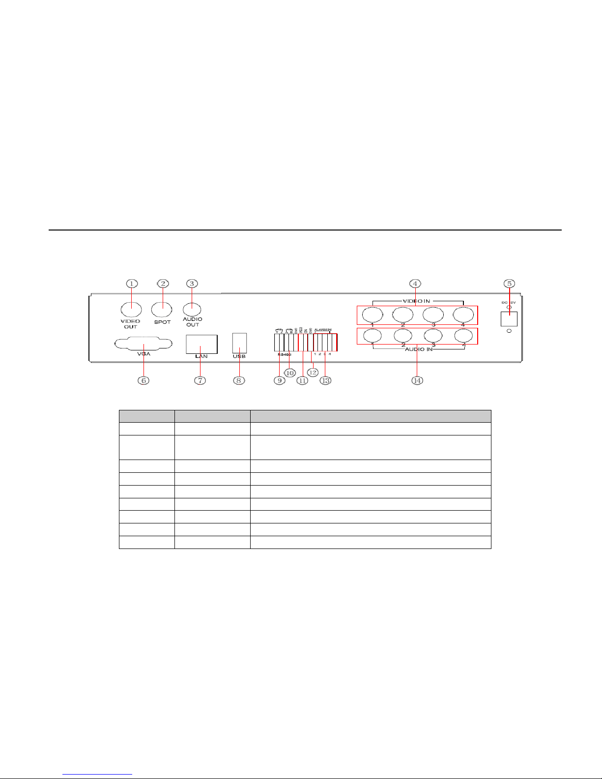
The Rear Panel Interface for 8-ch is shown in Fig 2.4:
Fig 2.4 Rear Panel for 8-ch
Item Name Description
1 Video out Connect to monitor
2 Spot out
Connect to monitor as an AUX output channel by channel. Only
video display, no menu show
3 Audio out Audio output, connect to the sound box
4
Video in
Video input channels from 1-8

Digital Video Recorder User Manual
9
Item Name Description
5
DC12V
POWER INPUT
6
VGA port
VGA output, connect to monitor
7 LAN Network port
8
USB port
Connect USB mouse or connect external USB devices
9 P/Z Connect to speed dome
10
K/B
Connect to keyboard
11
ALARM OUT
1-ch relay output. Connect to external alarm
12
+ 5V and GND
+5 V and Grounding
13
ALARM IN
Connect to external sensor 1-4
14
Audio in
4-ch audio input
2.4 Remote Controller
It uses two AAA size batteries and works after loading batteries as explained below:
Step 1: O pen the battery cover of the Remote Controller.
Step 2: Pl ac e batteries. Please take notice of the poles . (+ and -)
Step 3: Replace the battery cover.
Notice: Frequently check the following
1. Check poles of the batteries.
2. Check the remaining charge in the b atteries.
3. Check IR controller sensor is mask.
If it still doesn't work, please change to a new remote controller and try, or contact your dealer.
The interface of remote controll er i s shown in Fig 2.5 Remote Controller.

Digital Video Recorder User Manual
10
Fig 2.5 Remote Controller
Item
Name
Function
1 Power Button Soft switch off to stop firmware from running. Do it before power off.
2
INFO Button
Get information about the DVR like firmware version, HDD information
3 REC Button To record manually
4
Digital Button
Input digital or choose camera
5 Multi Screen Button To choose multi screen display mode
6
SEARCH Button
To enter search mode
7 MENU Button To enter menu
8
ENTER Button
To confirm the choice or setup
9 Direction Button Move cursor in setup or pan/tilt PTZ
10
+/- Button
To increase or decrease the value in setup
11 Playback Control Button To control playback, fast forward/rewind/stop/single frame play
12
AUDIO Button
To enable audio output in live mode
13 Auto Dwell Button To enter auto dwell mode

Digital Video Recorder User Manual
11
Item
Name
Function
14 BACKUP Button To enter backup mode
15 PTZ Control Button
To control PTZ camera:
Move camera/ZOOM/FOCUS/IRIS/SPEED control
Operation processes with remote controller to control multi-DVR
The device ID of the DVR is 0. When using remote controller to control a s ingle DVR, it’s not necessary to reset the device
ID, user can do operation directly; when controlling multiple DVRs with a remote controller, please refer to the steps below:
Step 1: Activate remote controller to control DVR: enable DVR: turn the I R s ensor of the remote controller to the IR
receiver that’s on the front panel, press the number key 8 twice, then input device ID (Range from: 0-65535; the default
device ID is 0) with other digital number: 0-9, after that, press ENTER button to confirm.
Step 2: Us er can check the device ID by entering i nto System configuration Basic co nfiguration device ID. User can
also set other DVRs with the same device ID. For convenience, we don’t recommend user to set the device ID too long.
Step 3: Cancel controller to control DVR: turn the IR sensor of the remote controller to t he IR receiver that’s on the front
panel, press the number key 8 twice, then input the device ID that needs to be cancelled from controlling, press ENTER
button to confirm. After that, the DVR will not be controlled by remote controller.
2.5 Control with Mouse
2.5.1 Connect Mouse
It supports USB mouse through the ports on the rear panel.
Notice: If mouse is not detected or doesn't work, chec k the steps below:
1. Make sure the mouse plugs into the USB mo us e port not the USB port.
2. Change to a different mouse to try.

Digital Video Recorder User Manual
12
2.5.2 Use Mouse
In li ve:
Double-click left button on one camera to display full screen. Double-click again to return to the previous screen.
Click right button to show the control bar at the bottom of the screen as Fig 4.1 Menu Toolbar. Click right mouse again to
hide the control bar.
In setup:
Click left button to enter. Click right button to cancel setup, or return to the previous display.
If want to input a value, move cursor to a blank and click. An input keyboard will appear like in Fig 2.6. It inputs digitals,
letters, and symbols.
Fig 2.6 Digital Numbers and Letters Input Keyboard
User can change some values with the mouse wheel, such as time. Move cursor onto the value and roll the wheel when the
value blinks.
It also supports mouse drag (Example: Set motion detection area: click customized, hold left button, and drag to set motion
detection area.)
In playback:
Click left button to choose the options. Click right button to return to live mode.

Digital Video Recorder User Manual
13
In backup:
Click left button to choose the options. Click right button to return to previou s pi c ture.
In PTZ control:
Click left button to choose the buttons to control the PTZ. Click right button to return to live.
Notice:
Mouse is the default tool in all the operations above.
3 Basic Function Instruction
3.1 Power On/Off
Before you power on the unit, please make sure all the connections are good.
3.1.1 Power On
Step 1: Con nect with the source power. This turns on the power.
Step 2: The device will be loaded and the power indicator will display blue.
Step 3: Bef ore start, a WIZARD window will be pop-up and sho w som e information about time zone, time setup, network
configuration, record configur ation, and disk management. User c an setup here and refer to the concrete set up steps from
the corresponding chapters. If user doesn’t want to setup Wizard, please cli c k Exit button to exit.
After the device power goes on, if there is no menu or only has live image display, user can long press ESC button to
switch.
Notice: This serial device can only display menu on VGA monitor or BNC monitor at one time. If there is live image
display without menu display, please check whether other device has menu display first, or long press ESC key to wait for
login dialog box to appear. Long press ESC key can switch the output betw een BNC and VG A.

Digital Video Recorder User Manual
14
3.1.2 Power Off
User can power off the device by using remote controller, keyboard, and mouse.
By remote controller:
Step 1: Press Power button and the shut down window will appear. Click OK and the unit will power off after a while.
Step 2: Disc onnect the source power.
By keyboard and mouse:
Step 1: Ent er into
Menu, select “Shut Down” icon, and the Shut down window will appear.
Step 2: Click OK and the unit will power off after a while.
Step 3: Disc onnect the source power.
3.2 Login
User can login and logout the DVR system. Once logged out, user cannot do any other operations except changing t he
multi-screen display.
Fig 3.1 Login
Notice: The default user name and password is “admin” and 123456”. For detailed steps to change password, add,
or delete user, please refer to “4.7 User Management Configuration” for more details.

Digital Video Recorder User Manual
15
3.3 Live Preview
Fig 3.2 Live Preview Interface
3.3.1 Live Playback
Click Play button to playback the recorded videos. Refer to Figure 3.3. User can do concrete oper ation by clicking the
buttons on screen.
Fig 3.3 Live Playback
Symbol
Meaning
Green
Manual record
Yellow
Motion detection record
Red
Sensor Alarm record
Blue
Schedule record
Digital Video Recorder User Manual
16
4 Main Menu Setup Guide
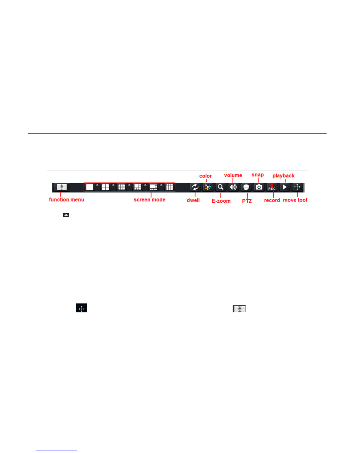
Click right mouse or press ESC button on the front panel and the control bar will display on the bottom of the screen. Refer
to Fig 4.1.
Fig 4.1 Menu Toolbar
Click the icon beside the screen display mode to display a channel select dialog. Images can drag to any place to
display in the live interface.
Dwell: Range of selecting to dwell is for 1/4/6/8 picture preview mode.
Color: User can adjust the color of live pictures.
E-Zoom: Single channel large screen electronic amplification. Left click the channel which needs to amplify and click
E-Zoom to amplify the image. Press left mouse to drag the cursor to view different parts of the image. Double-click the left
mouse to exit. Click the right mouse to return to the main interface.
Volume: Enable sound.
PTZ: User can control rotation position, speed of the dome, start track, auto scan, and cruise in this interface. User can
refer to PTZ configuration for more details .
Snap: User can snap the live pictures. These pictures will automatically be saved in the SATA disk.
Record: User can start manual record.
Playback: Device can playback the recorded files.
User can click
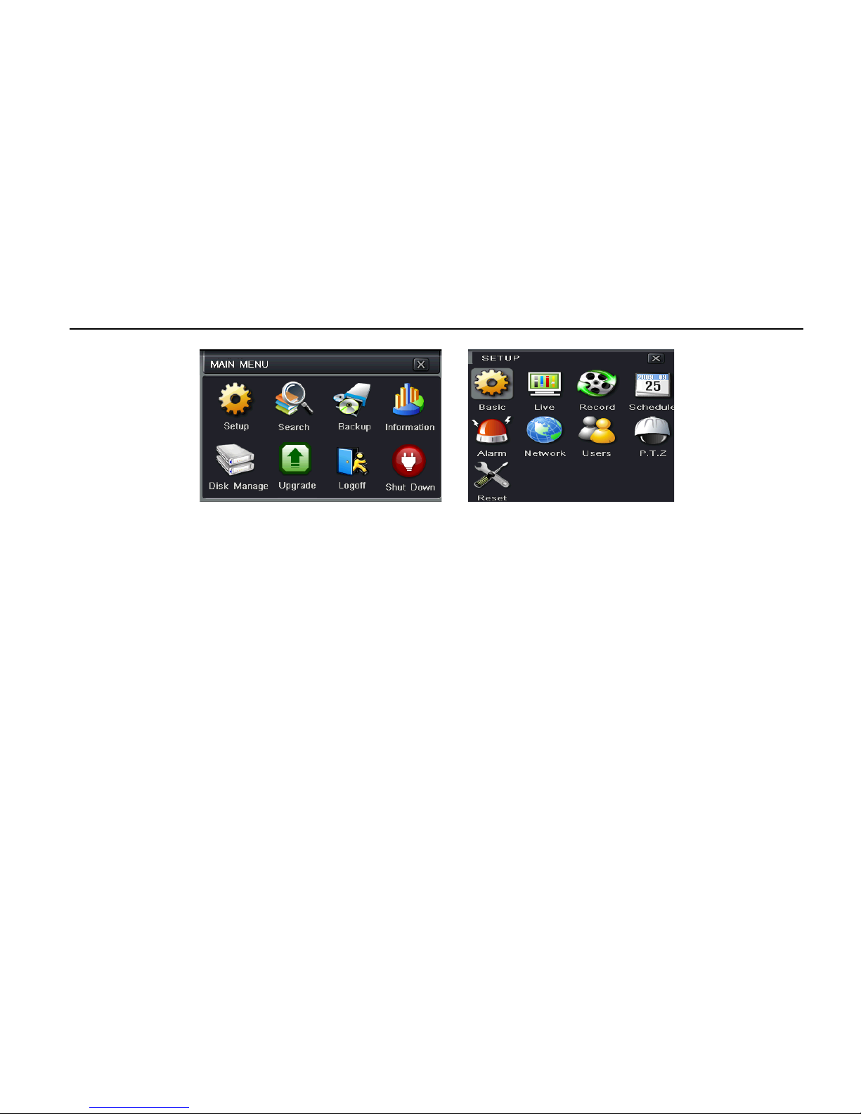
button and drag it anywhere with the left mouse. Click Menu button and the interface will
pop-up like in Fig 4.2; pressing the MENU button on the front panel or operating with the remote controller can also display
Digital Video Recorder User Manual
17
the main menu. Click Setup icon will pop-up the configuration menu:
Fig 4.2 Main Menu Configuration Menu
4.1 Basic Configuration
Basic configuration includes three sub menus: system, date & time, and DST.
4.1.1 System
Step 1: Ent er into system configuration ba s i c configuration system.
Step 2: In this interface, user can setup the devic e nam e, device ID, video format, max online users, Video Output and
language, Screensaver and so on. The defin itions for every parameters display as below:
Device Name: Name of the device. It may display on the client end or CMS that help user to recognize the device
remotely.
Video Format: Two modes: NTSC and PAL. User can select the video format according to the camera.
Password Check: Enable this opt ion. User needs to input user name and password to d o corresponding operations wit h
the relevant right in system configuration.
Show System Time: Displays time in live.
Startup Wizard: Tick off this item and it will display an opening wizard with time zone and time setup information.

Digital Video Recorder User Manual
18
Max Online Users: Set the max user amount for network connection.
Video Output: The resolution of live display interface ranges from: VGA 800*600, VGA 1024*768, VGA 1280*1024 and
CVBS.
Note: When switching between VGA and CVBS, it will change the menu output mode. Please connect to relevant
monitor.
Language: Setup the menu language.
Note: After changed the language and video output, the device needs to login again.
Logout After (Minutes): A user can setup the screen interval time (.5, 1, 3, 5, Never). If there is no operation within the
setting period, the device will aut o logout and return to login interfac e.
No Image When Logout: If this item is selected, there will be no image showing when logged out.
4.1.2 Time & Date
Step 1: Ent er into system configuration basic
configuration time & date. Refer to Fig 4.3.
Step 2: Set the date format, time format, time zone in
this interface. User can also adjust system date
manually.
Step 3: Click “default” button to set default setting. Click
“apply” button to save the setting. Click “exit” button to
exit current interface.
Fig 4.3 Basic Configuration - Time & Date
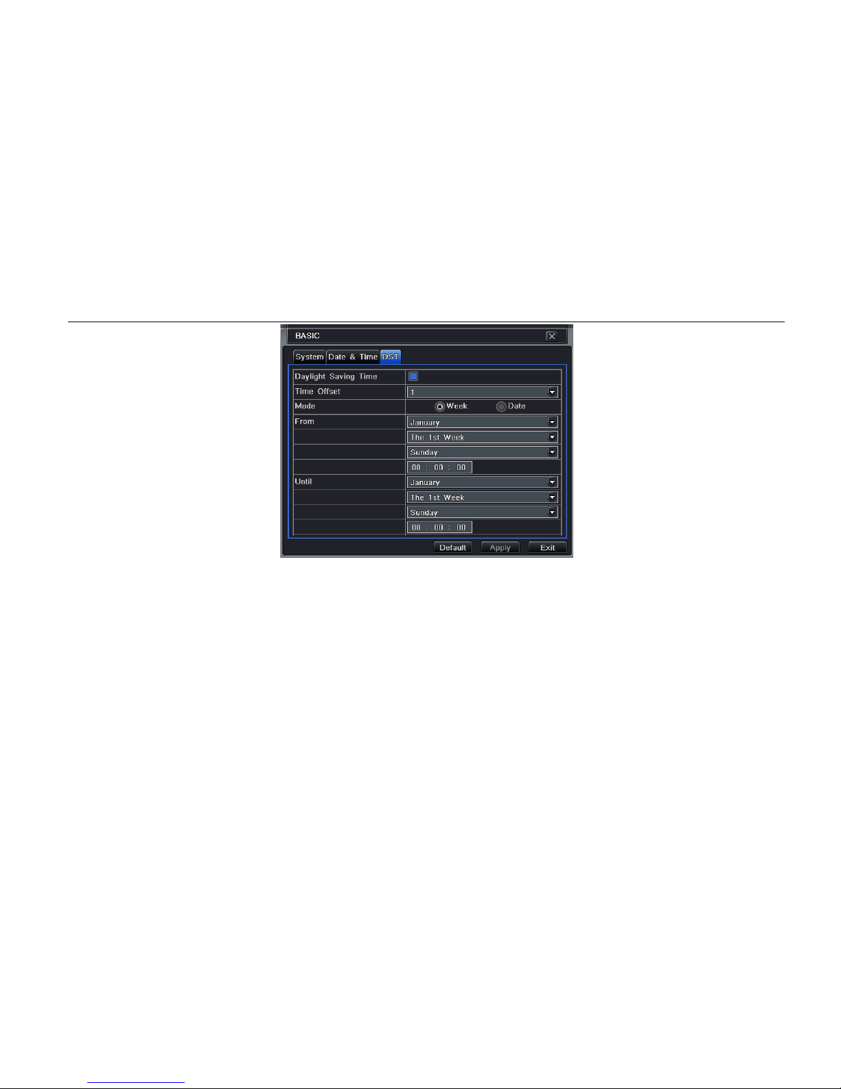
4.1.3 DST
Step 1: Enter into system configuration basic configuration DST. Refer to Fig 4.4.
Digital Video Recorder User Manual
19
Fig 4.4 Basic Configuration - DST
Step 2: In this interface, enable daylight saving t ime, time offset, mode, start & end month/week/date, etc.
Step 3: Click “default” button to set default setting. Click “apply” button to save the setting. Click “exit” button to exit current
interface.
4.2 Live Configuration
Live configuration includes four submenus: live, main monitor, spot, and mask.
4.2.1 Live
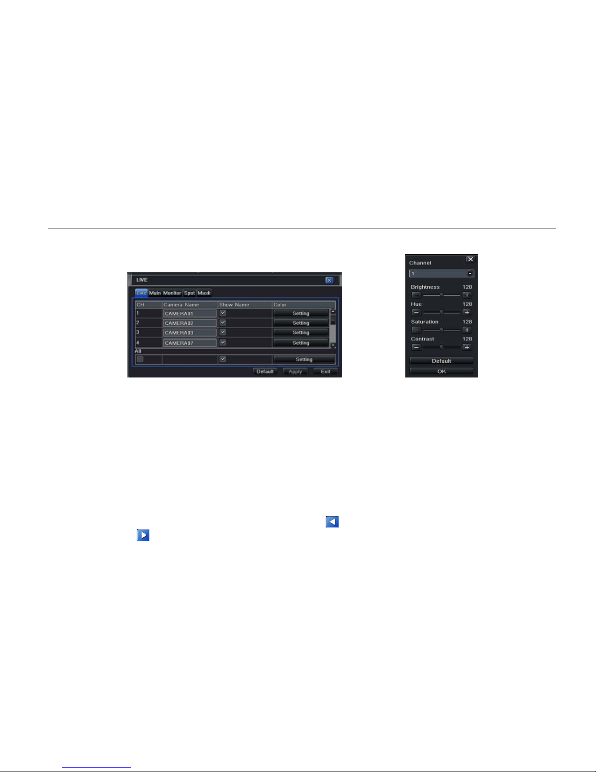
In this interface, user can setup camera name, adjust colors to brightness, hue, saturation, and contrast.
Step 1: Enter into system configuration live configuration live. Refer to Fig 4.5.
Note: Click Camera Name to see an input keyboard. User can name the camera. Click Shift button to input Capital
Digital Video Recorder User Manual
20
letters and click Shift button again to input Chinese characters.
Step 2: Tick off camera name and click “setting” button to display a window like Fig 4.7.
Fig 4.5 Live Configuration – Live Fig 4.6 Live - Color Adjustment
Step 3: In this interface, user can adjust brightness, hue, saturation, and contrast in live. Click “default” button to set default
setting and click “OK” button to save the setting.
Step 4: User can setup all channels with same parameters, please tick off “all” and then do relevant setup.
Step 5: Click “default” button to set default setting. Click “apply” button to save the settin g and click “exit” button to exit
current interface.
4.2.2 Main Monitor
Step 1: Enter into system configuration live configuration main monitor. Refer to Fig 4.7.
Step 2: Select split mode: 1×1, 2×2, 2×3, and 3×3.
Step 3: Dwell time: The time interval for a certain dwell picture display switching to next dwell picture display.
Step 4: Select split mode and setup current picture group. Click
button to setup the previous channel groups of dwell
picture and click button to set the latter channel groups of dwell picture.

Digital Video Recorder User Manual
21
Step 5: Click “default” button to set to default s etting.
Click “apply” button to save the setting. Click “exit”
button to exit current interface.
Fig 4.7 Live Configuration - Host Monitor
4.2.3 Spot
Step 1: Enter into system configuration live configuration spot. Refer to Fig 4.8.
Step 2: Select split mode: 1×1 and channel of choice.
Step 3: Dwell time: The time interval for a certain dwell
picture display switching to next dwell picture display.
Step 4: Select split mode and setup curre nt picture
group. Click button t o s etup the previous channel
groups of dwell picture. Click
button to set the latter
channel groups of dwell picture.
Step 5: Click “default” button to set to default setting.
Click “apply” button to save the setting. Click “exit”
button to exit current interface.
Fig 4.8 Live Configuration - Spot
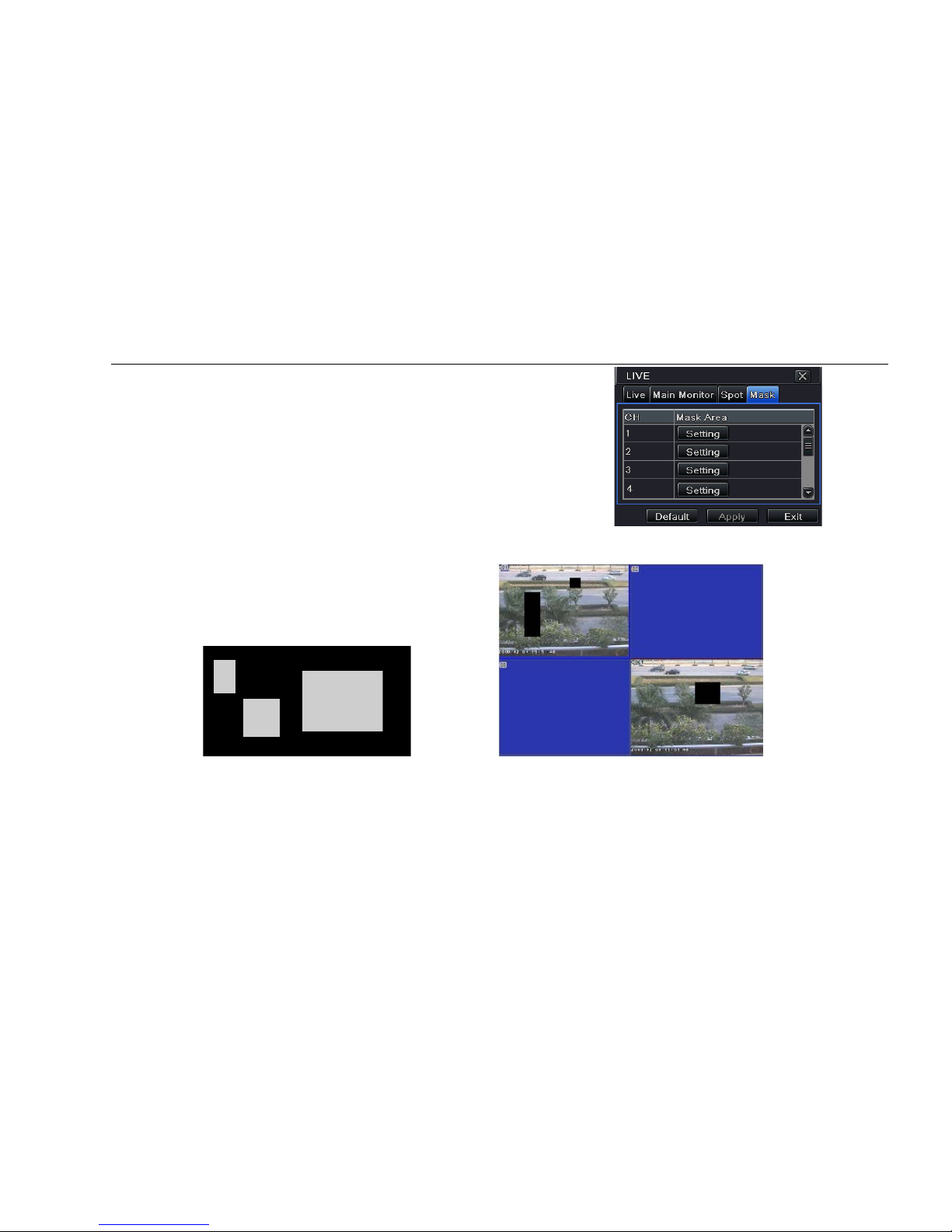
4.2.4 Mask
User can setup private mask area on the live image picture, max threes areas.
Enter into system configuration live configuration mask. Refer to Fig 4.9.
Digital Video Recorder User Manual
22
Setup mask area: Click setting button under mask area
and enter into live image. Press left mouse and drag
mouse to set mask area, refer to below picture. Click
Apply button to save the setting.
Delete mask area: Select a certain mask area and click
left mouse to delete that mas k area. Click Apply button
to save the setting.
Fig 4.9 Live Configuration - Mask
Setup Mask Area Live Image Mask Area
Digital Video Recorder User Manual
23
4.3 Record Configuration
Record configuration includes s i x sub menus: enable, record bit rate, time, recycle record, stamp, and snap.
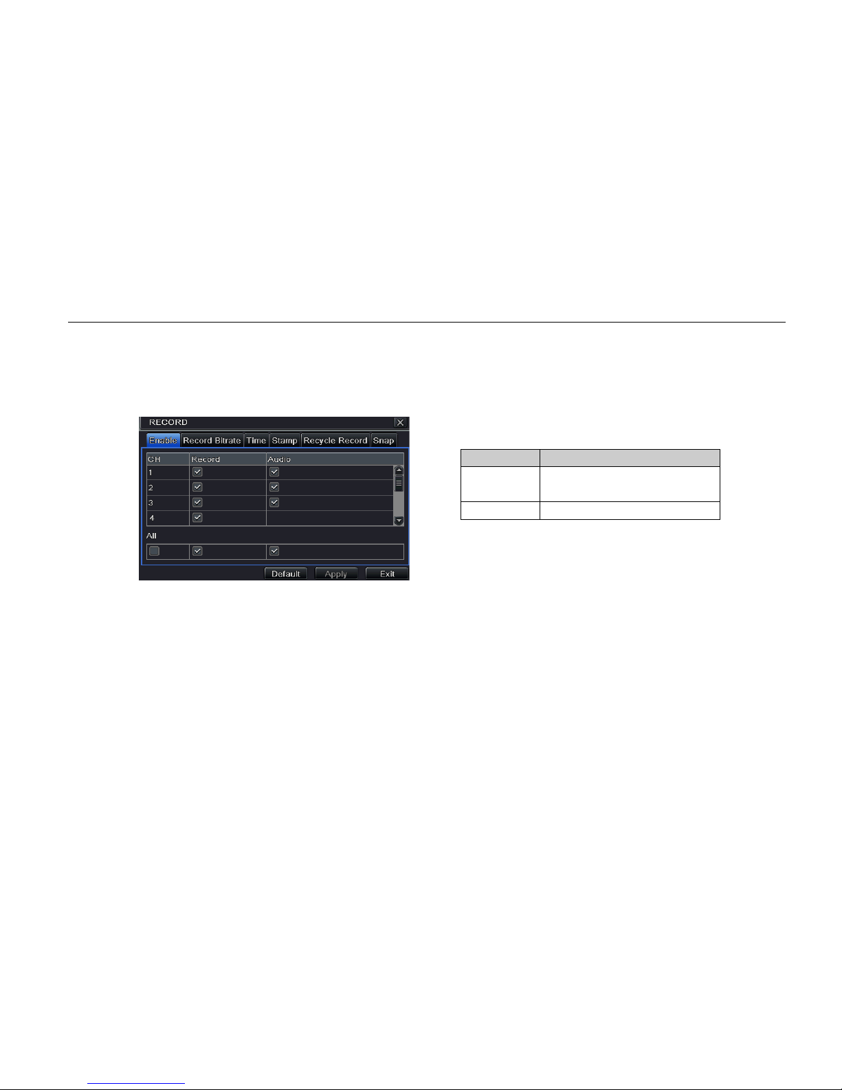
4.3.1 Enable
Step 1: Enter into system configuration record configuration enable. Ref er to Fig 4.10.
Fig 4.10 Record Configuration - Enable
Step 2: Tick off record and audio.
Step 3: User can setup all channels with sam e parameters, tick off “all” and then do relevant setup.
Step 4: Click “default” button to set to default setting. Click “apply” button to save the setting and click “exit” button to exit
current interface.
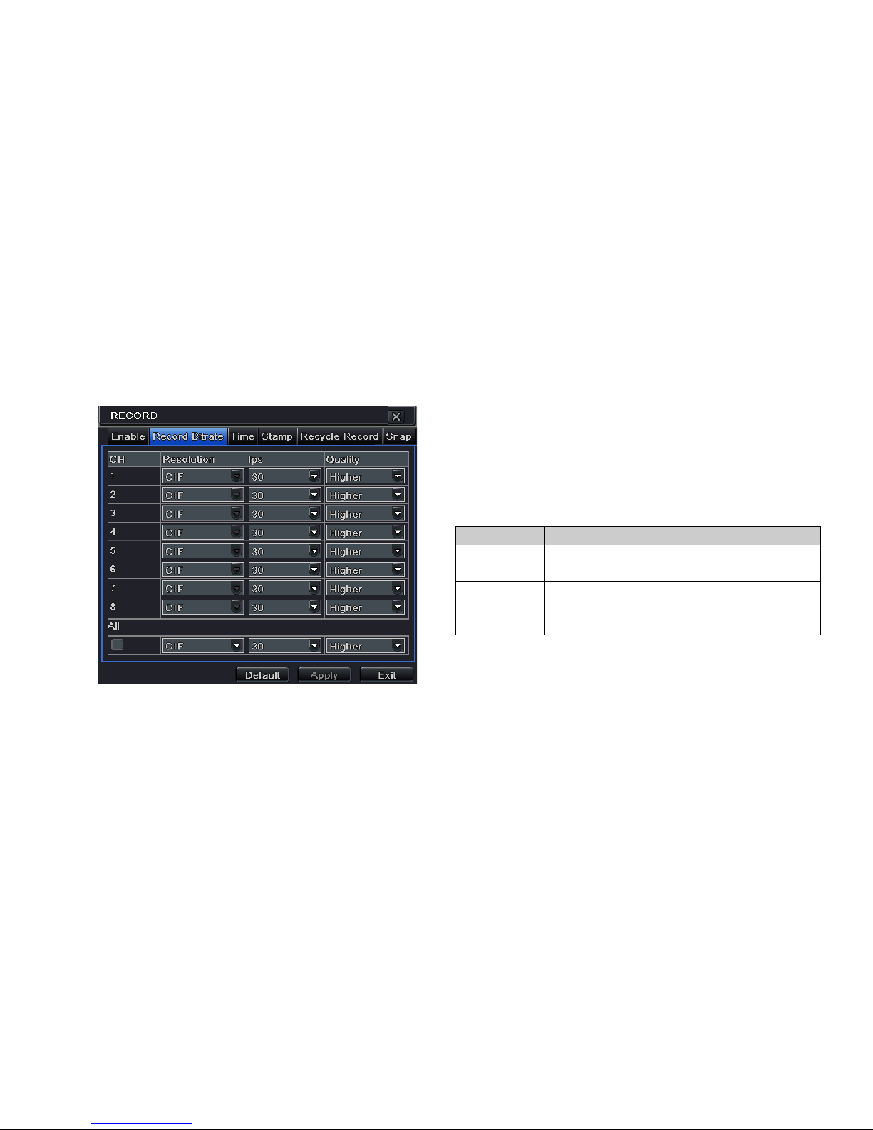
4.3.2 Record Bitrate
Step 1: Enter into system configuration record configuration record bitrate. Refer to Fig 4.11.
Step 2: Setup rate, resolution, and quality.
Step 3: User can setup all channels with same parameters, tick off “all” and then do relevant setup.
Step 4: Click “default” button to set to default setting. Click “apply” button to save the set ting and click “exit” button to exit
Parameter
Meaning
Record Record switch of ever y
channels
Audio
Enable live record audio
Digital Video Recorder User Manual
24
current interface.
Note: If the rate value set is over high the maximum resources of the device, the value will be adjusted
automatically.
Fig 4.11 Record Configuration - Record Bitrate
4.3.3 Time
Step 1: Enter into system configuration record configuration time. Ref er to Fig 4.12.
Pre-alarm record time: The record time before event happens i.e. record time before motion detecti on or sensor
alarm is triggered.
Parameter
Meaning
Resolution
Support CIF
FPS
Ranges from 1-30 (NTSC), 1-25 (PAL)
Quality The higher the value is, the clearer the
recorded image is. Six options: lowest,
lower, low, medium, higher and highest.

Digital Video Recorder User Manual
25
Post-alarm record: Set the post recording time after the alarm is finished. Options: 10s, 15s , 20s, 30s, 60s, 120s,
180s and 300s.
Expire time: The hold time of saved records . If the set date is overdue, the record files will be deleted automatically.
Step 2: User can setup all channels with sam e parameters. Tick off “all” to do relevant setup.
Step 3: Click “default” button to set to default s etting. Click “apply” button to save the sett ing and click “exit” button to exit
current interface.
Fig 4.12 Record Configuration - Time
4.3.4 Stamp
Stamp: User can overlap the channel name and time stamp on video.
Step 1: Enter into system configuration record configuration stamp. Refer to Fig 4.13.
Fig 4.13 Record Configuration - Stamp

Digital Video Recorder User Manual
26
Step 2: Tick off camera name and time stamp. Click Setting button and then user can use cursor to drag the camera name
and time stamp in random positions. Pleas e refer to below Figures:
Before drag After drag
Step 3: User can also setup all channels with s ame parameters.
Step 4: Click “default” button to set to default setting. Click “apply” button to save the setting and click “exit” button to exit
current interface.
4.3.5 Recycle Record
Step 1: Enter into system configuration record configuration recycle record.
Step 2: Tick off recycle record to enable the recycle record function. It will cover the earlier recorded files and keep
recording when HDD is full. If dis-enabled, it will stop recording when HDD is full.
Step 3: Click “default” button to set to default s etting. Click “apply” button to save the sett ing and click “exit” button to exit
current interface.
4.3.6 Snap
In this interface, user can set up resolution, quality, snap interval, snap number.
4.4 Schedule Configuration
Schedule configuration includes three sub menus: schedule, motion, and alarm.

Digital Video Recorder User Manual
27
4.4.1 Schedule
The row means seven days of a week from M onday to Sunday and the column means 24 hours of a day. Click the grid to
do relevant setup. Blue means selected area, gray means unselected area.
Fig 4.14 Schedule Configuration - Schedule
Step 1: Select channel, double-click, and a dialog box will pop-up like in Fig 4.15 where user can edit week schedule.
Fig 4.15 Schedule - Week Schedule
① Click “add” button to add a certain day schedule. Click “delete” button to delete the selected s chedule.
Copy: User can copy the specify schedule to other dates.
Click “OK” button to save the setting and click “Exit” button to exit current interface.
② User can apply the schedule setting of certain channel to other or all channels. Just select c hannel and click
“Copy” button.
Step 3: Click “apply” button to save the setting.

Digital Video Recorder User Manual
28
4.4.2 Motion
Step 1: Enter into system configuration schedule configuration motion. Refer to Fig 4.16.
Step 2: The setup steps of motion are familiar with schedule. User can refer to “4.4.1 Schedule” for details.
Fig 4.16 Schedule Configuration - Motion
Note: The default schedule of motion detection is full-selected, that is, the color of schedule setting interf ace is
blue.
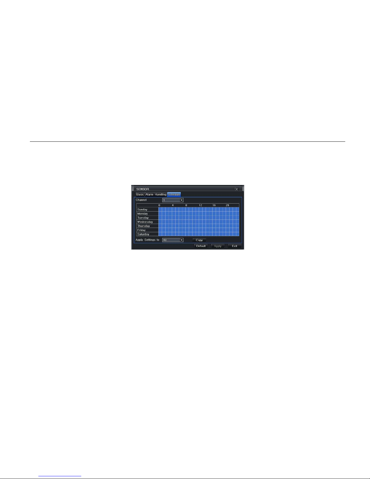
4.4.3 Sensor
Step 1: Enter into system configuration schedule configuration alarm. Refer to Fig 4.17.
Fig 4.17 Schedule Configuration - Sensor

Digital Video Recorder User Manual
29
Step 2: The setup steps of alarm are familiar with schedule. User can refer to “4.4.1 Schedule” for details.
Note: The default schedule of sensor is full-selected, that is, the color of schedule setting interface is blue.
4.5 Alarm Configuration
Alarm configuration includes f i v e sub menus: sensor, motion, video loss, other alarm, and alarm out.
4.5.1 Sensor
Sensor includes three sub menus: basic, alarm handling, and schedul e.
① Basic
Step 1: Enter into system configuration alarm configuration sensor basic. Refer to Fig 4.18.
Step 2: Enable sensor alarm and set the alarm type according to triggered alarm type. Two option: NO and NC.
Step 3: User can setup all channels with same parameters. Please tick off “all” and t hen do relevant setup.
Step 4: Click “default” button to set to default s etting and click “apply” button to save the setting. Click “exit” button to
exit current interface.
Fig 4.18 Alarm Configuration - Sensor - Basic

Digital Video Recorder User Manual
30
② Alarm handling
Step 1: Enter into system configuration alarm configuration sensor alarm handling. Refer to Fig 4.19.
Step 2: Select hold time and click Trigger button. Then a dialog box will pop -up as Fig 4.20.
Fig 4.19 Alarm Configuration - Sensor - Alarm Handling Fig 4.20 Alarm Handling - Trigger
Step 3: After selecting Buzzer, there will be triggered buzzer alarm out.
Full screen alarm: When triggered alarm, an al ar m full screen will pop up.
Email: Tick off this function. When an alarm is triggered, a notification email will be sent to user’s designed email box
including trigger events, time, snap pictures, device name, ID camera name etc.
Snap: Select channels. When an alarm is triggered, the system will automatically save the captured pictures from t he
selected channel. If user ticks off Email function, these pictures will also be sent to user’s designed email box.
To alarm out: When selecting the channel, there will be triggered alarm out in the designated channel. Click OK
button to save the setting and c li c k Exit button to exit the current interfac e.
To record: Tick off recording channels. It will record the camera when alar m is triggered. Click OK button to save the
setting and click Exit button to exit t he current interface.
To P.T.Z: Set linked preset and cruise for alarm. User can select any channel and multi channels as linked channels.
Click OK button to save the setting and click Exit button to exit the current interface.
Digital Video Recorder User Manual
31
Step 4: User can also setup all channels with s ame parameters.
Step 5: Click “default” button to resort default setting; click “apply” button to save the setting; click “exit” button to exit
current interface.
③ Schedule
Step 1: Enter into system configuration alarm configuration sensor schedule. Refer to Fig 4.21.
Fig 4.21 Sensor - Schedule
Step 2: The setup steps of sensor schedule are similar with schedule. Use r can refer to “4.4.1 Schedule” for details.
Note: the default schedule of sensor is full-selected, that is, the color of schedule settin g interface is blue.
4.5.2 Motion
Motion includes two sub menus: moti on and schedule.
① Motion
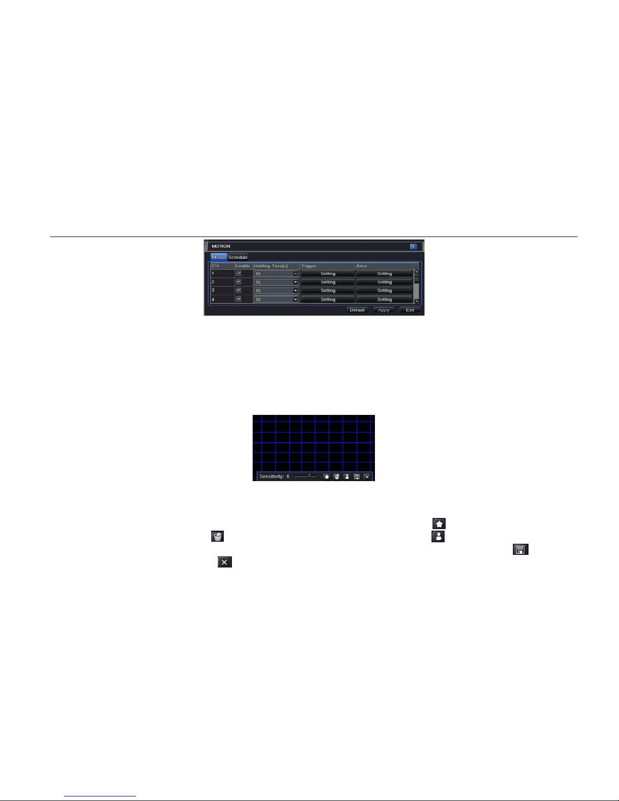
Step 1: Enter into system configuration alarm configuration motion. Refer to Fig 4.22.
Digital Video Recorder User Manual
32
Fig 4.22 Motion
Step 2: Enable motion alarm and set alarm hold t ime which means time interval between two adjacent detective
motions. If there is other motion detected during the interval period, this is considered continuous movement.
Otherwise, it will be considered that those two adjacent detective motions are two different motion events.
Click Trigger button to pop up a dialog box.
Step 3: The setup steps of motion trigger are similar with alarm handling. User can refer to “Chapter 4.5.1 Sensor
Alarm Handling” for more details.
Step 4: Click Area button to pop-up a window like in Fig 4.23.
Fig 4.23 Motion - Area
Step 5: In the Area interface, user can drag slide bar to set the sensitivity value (1-8). The default value is 4. The
higher the value is the higher sensitivity you get. Due to sensitivity being influenced by color and time (da y or
night), user can adjust its value according to the practical conditions. Click
icon, set the whole area as
detection area. Click
icon, the set detection area will be cleared. Click icon, user can test whether the
sensitivity value and motion area ar e s uitable accordingly (refer to the follo wing picture). Click
icon, to
save the setting. Click icon, exit current interface.

Digital Video Recorder User Manual
33
Note: when user drag mouse to set motion detection area, they have to cli ck
icon to clear all set detection
area firstly, and then make the operation.
Step 6: User can also setup all channels with s ame parameters.
Step 7: Click “default” button to set to default setting. Click “apply” button to save the setting and click “exit” button to
exit current interface.
② Schedule
Step 1: Enter into system configuration alarm configuration schedule. Refer to Fig 4.24.
Step 2: The setup steps of alarm schedule are similar with schedule. User can refer to “4.4.1 Schedule” for details.
4.5.3 Video Loss
Step 1: Enter into system configuration alarm configuration video los s. Refer to Fig 4.25.
Step 2: The setup steps of video loss trigger are similar with alarm handling. User can refer to “4.5. 1 S ensor alarm
handling” for more details.
Step 3: User can also setup all channels with same parameters.
Step 4: Click “apply” button to save the setting and click “exit” button to exit current interface.

Digital Video Recorder User Manual
34
Fig 4.24 Alarm Configuration - Schedule Fig 4.25 Alarm Configuration - Video Loss
4.5.4 Other Alarm
Step 1: Enter into system configuration other alarm. Refer to Fig 4.26.
Disk full: User can choose the capacity of the disk storage and se l ec t the related alarm. If the disk is full, the system will
alarm according to the setup.
IP conflict: If there is an IP address conflict within the same network, the device will alarm after user selects buzzer and
the channel to alarm out.
Disconnect: If there’s a disconnection, t he device will alarm after the user selects buzzer and t he channel to alarm out.
Disk Warning: If the disk reduces, the system will send email to the designated mailbox or alarm to notify the reducing
information after the user has select ed the corresponding function.
Step 2: The setup steps of Buzzer , Email, and Alarm Out are similar with alarm handling. User can refer to “4.5.1 Sensor
alarm handling” for more details.
Step 3: Select a hard disk in the pull down list box. When the disk capacity is lower than that value, there will appear some
text information on the lower right of the live image.
Step 4: Click “default” button to set to default s etting. Click “apply” button to save the sett ing and click “exit” button to exit
current interface.

Digital Video Recorder User Manual
35
Fig 4.26 Other Alarm
4.5.5 Alarm Out
Alarm out includes three sub menus: alarm out, schedule, and buzzer
① Alarm out
Step 1: Enter into system configuration alarm out. Refer to Fig 4.27.
Step 2: In this interface, set relay alarm out name, select hold time which means the interval time between the two adjacent
alarms.
Step 3: User can setup all channels with same parameters. Tick off “all” to do relevant setup.
Step 4: Click “apply” button to save the setting and click “exit” button to exit current interface.
② Schedule
Step 1: Enter into system configuration schedule.
Step 2: The setup steps of alarm out schedule are
similar with schedule. User can refer to “4.4.1 Schedule”
for details.
Note: The default schedule of motion detection is
full-selected, that is, the color of schedule setting
interface is blue.
Fig 4.27 System Configuration - Alarm Out
③ Buzzer

Digital Video Recorder User Manual
36
Step 1: Enter into system configuration buzzer
Step 2: Tick off Buzzer, set buzzer alarm hold time.
4.6 Network Configuration
Network configuration includes four submenus: network, sub stream, e-mail, and other settings.
4.6.1 Network
Step 1: Enter into system configuration network configuration network. Refer to Fig 4.28.
Step 2: HTTP port: the default value is 80. If the value changes, user needs to add the port number when typing IP address
in IE. For example: if HTTP port is set to 82 with IP address: http://192.168.0.25, user needs to input http://192.168.0.25:82
into IE browser.
Server port: communication port
Step 3: After selecting "Obtain an IP address automatically", the device will distribute IP address, subnet mask, and
gateway IP and DNS server.
Step 4: Enable PPPoE to directly connect the DVR to internet via ADSL and then input the user name and password. Click
TEST button to test the effectiveness of the relevant information.
Fig 4.28 Network Configuration – Network

Digital Video Recorder User Manual
37
4.6.2 Sub Stream
Step 1: Enter into system configuration network configuration sub stream. Refer to Fig 4.29.
Step 2: Select fps, resolution, and quality.
Step 3: User can also setup all channels with same parameters.
Step 4: Click “apply” button to save the setting and click “exit” button to exit curr ent interface.
Fig 4.29 Network Configuration - Sub Stream
4.6.3 Email
Step 1: Enter into system configuration network configuration email. Refer to Fi g 4.30.
SMTP Server/Port: The name and port number of SMTP server. After selecting “This server requires a secure connection
(SSL)”, user can setup mail servers (such as Gmail) according to actual needs.
Send address/password: Sender’s email address/password
Receive address: Receiver’s email address. Here user can add at least t hree email addresses.
Click TEST button to test the validity of the mailbo x.
Attaching image: Tick off this item. The system will attach images when sending the emails.
Parameter
Meaning
FPS
Range from: 1-30 (NTSC) 1-25 (PAL)
Resolution
Support CIF
Quality
The higher the value, the clearer the
record image is. Six options: lowest,
lower, low, medium, higher and highest.

Digital Video Recorder User Manual
38
Fig 4.30 Network Configuration - Email
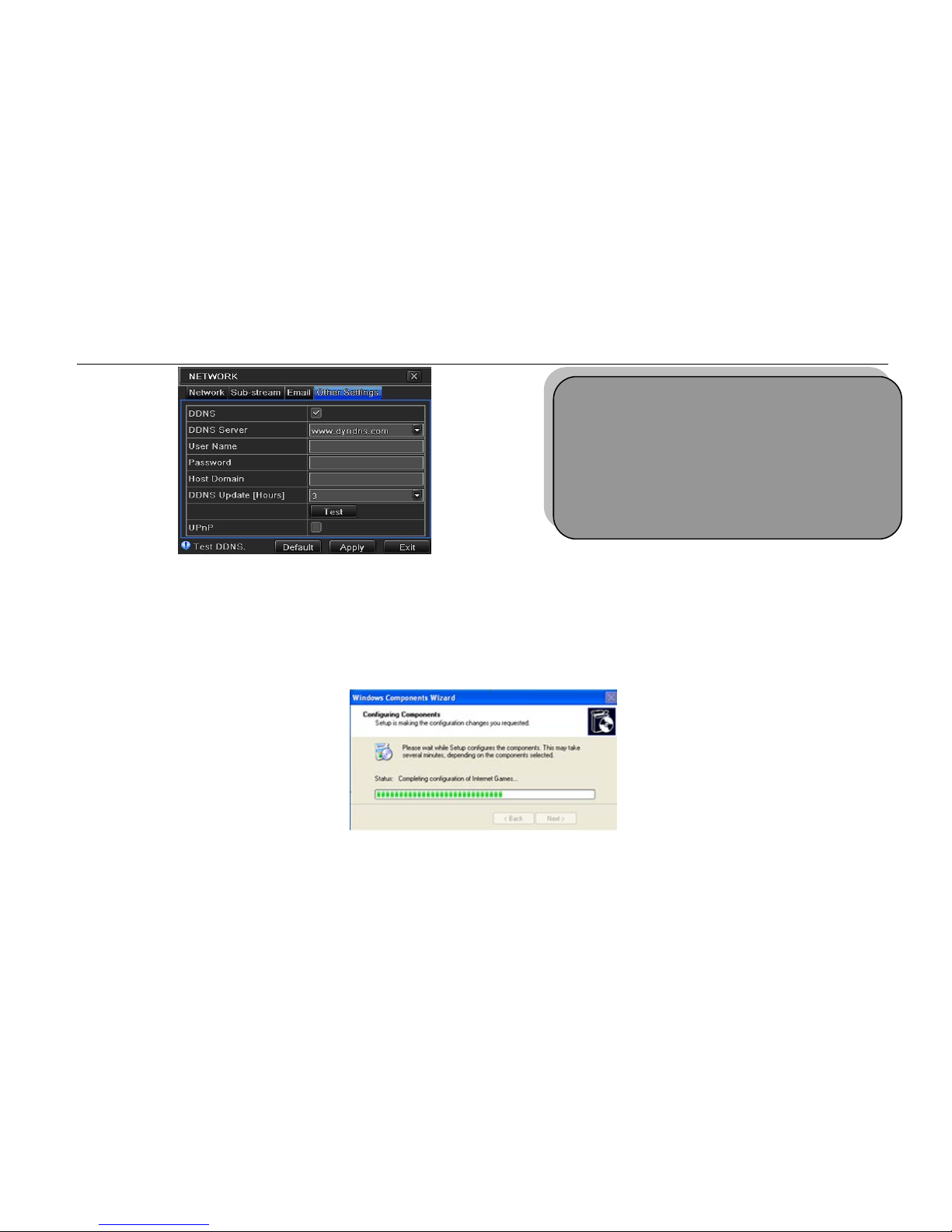
4.6.4 Other Settings
Step 1: Enable DDNS server: user needs to input us er name, password, and host domain name of the registered website.
Click TEST to test the effectiveness of the relevant information.
Step 2: Click “default” button to set to default setting. Click “apply” button to save the setting and click “exit” button to exit
current interface.
Digital Video Recorder User Manual
39
Fig 4.31 Network Configuration - Other Settings
Enable UPnP: User may select UPnP and then enable UPnP function in the user’s router. Then user can access DVR
through WAN. When accessing the DV R through IE, user can check the IP address by the following method: Double-click
the “My Network Places” icon on the desktop in PC, select “Show icons for networked UPnP devices” in the “Network
Tasks” list box, an information windo w will pop up, click “YES” button, “Windows Components Wizard” dialog box will pop
up as shown as in the picture below, press “Next” to continue. After finishing the installation of configuring components, the
UPnP icons will display. Users can double-click certain icon and check the IP address of the device.
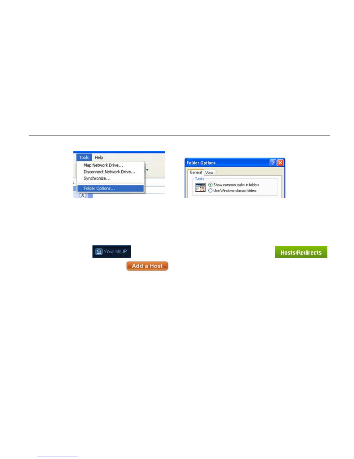
If “Show icons for networked UPnP devices” isn’t displayed in the “Network Tasks” list box, please follow the below
operation:
Note: The domain name server selected by user is a
banding domain name of DVR. User should log onto
the website, which is provided by the server supplier,
to register a username and password first and then
apply a domain name online for the server. After
successful application, user can access the server
from IE client by inputting that domain name.
Digital Video Recorder User Manual
40
Click “Tools” – “Folder Options”
Select the “Show common tasks in folders” in the “Tasks” check box to display the UPnP icon.
1. Domain name Registration (Take www.no-ip.com for example)
Note: Users can self-define the h ostname, username and password.
Input www.no-ip.com in the IE address bar. User can access the domain name registration interface.
Create user account and a confirmation e-mail will be sent. Click on the confirmation link sent to the e-mail and then user
can log in.
Once logged in, click
on the top r ight-hand corner of the webpage. Then click on
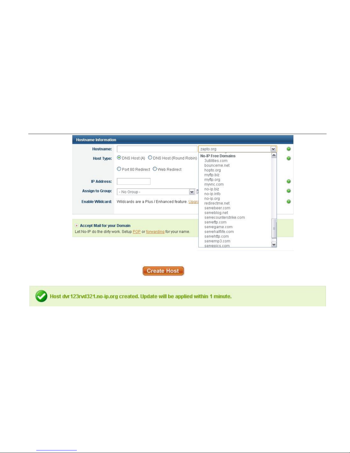
to enter a free domain name. Click and the following page will appear:
Digital Video Recorder User Manual
41
User can type in hostname of choice but if user wants a free domain, must click a domain under No-IP Free Domains List.
User’s IP Address should automatically be inputed, but if user wants to use a different IP Address, type it in.
After filling out the information and clicking
user will be directed to a page where they can manage,
delete, or add more hosts. On the top of that page, the following picture will appear to show that the host has been created.
Note: www.no-ip.com was free when this manual was made so we cannot guarantee that it will continue to be free.
Definitions and descriptions of network configuration:

Digital Video Recorder User Manual
42
DDNS server Website provided by dynamic domain name supplier. The
options: www.dyndns.com, www.no-ip.com, etc.
Username
Username to log into the website of domain name supplier
Password
Password to log into the website of domain name supplier
Host domain
The domain name user registered at the supplier’s website
Update interval
The interval time of upgrading DVR IP address
4.7 User Management Configuration
Step 1: Enter into system configuration user management configuration. Refer to Fig 4.32.
Step 2: After clicking Add button, a dialog box will pop-up like in Fig 4.33.
Fig 4.32 User Management Configuration Fig 4.33 Add - General
① General: Input username and password. Select user type: normal or advance. Input the MAC address of the PC.
Click OK button. This user will be added into the user list box. Clic k Exit button to exit the current interface.
Note: When the default value of bind ing P C MAC ad dress i s 0 , the user is not bind with the specify computer. User
can log in DVR on the binding computer after set the specific binding MAC address.
② Authority:
Step 1: Enter into add user authority referring to Fig 4.34.

Digital Video Recorder User Manual
43
Step 2: In the authority interface, assign the definite operation right for tha t user.
Step 3: In the user management interface, click Setup button to modify username, user type, and bin ding PC
MAC address.
Step 4: Select the user that user wants to delete in the user list box and then click Delete button to delete this
user.
Step 5: Click Change password button to modify th e password and then click Exit button to exit the curr ent
interface.
Fig 4.34 Add User - Authority
4.8 P.T.Z Configuration
P.T.Z Configuration includes two submenus: ser i al port and advance
① Serial port
Step 1: Enter into system configuration P.T.Z configuration serial port. Refer to Fig 4.35.
Step 2: Tick off Enable and then setup the value of address, baud rate, and protocol according to the settings of the speed
dome.

Digital Video Recorder User Manual
44
Step 3: User can setup all channels with sa m e parameters.
Fig 4.35 P.T.Z Configuration - Serial Port
Definitions and descriptions of serial port:
② Advance
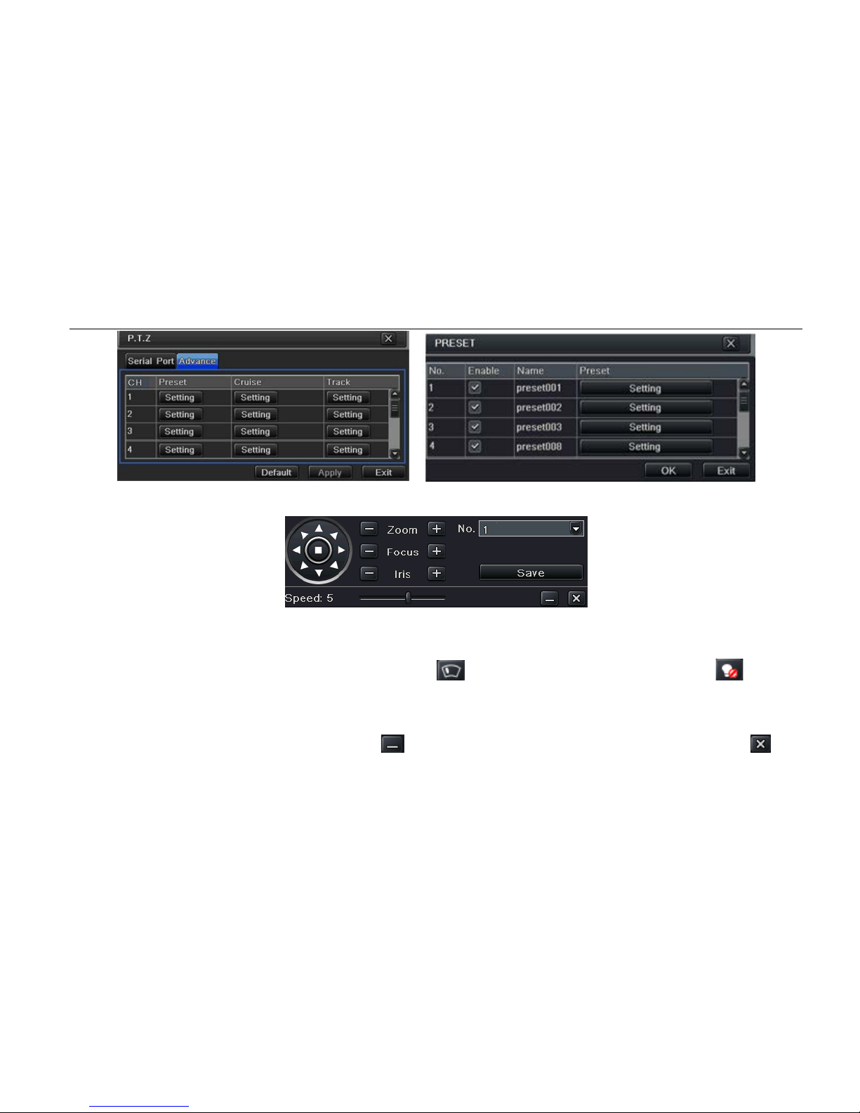
Step 1: Enter into system configuration P.T.Z configuration advance. Refer to Fig 4.36.
Step 2: In the Advance interface, after clicking preset “Setting” button, a dialog box will pop-up like in Fig 4.37.
Parameter
Meaning
Address
The address of the PTZ device
Baud rate Baud rate of the PTZ device. Range: 110, 300, 600, 1200, 2400, 4800,
9600, 19200, 34800, 57600, 115200, 230400, 460800, 921600.
Protocol Communication protocol of the PTZ device. Range: NULL, PELCOP,
PELCOD, LILIN, MINKING, NEON, STAR, VIDO, DSCP, VISCA,
SAMSUNG, RM110, HY, N-control.
Digital Video Recorder User Manual
45
Fig 4.36 P.T.Z Configuration - Advance Fig 4.37 Advance - Preset Setting
a) In the preset interface, click Set ting button to see a window like in Fig 4.38.
Fig 4.38 Preset - Setting
b) User can control the dome rotation: up, up left, down, right down, left, left down, right, and up right. User can also
stop rotation. Adjust the rotate speed and the value of zoom, focus, and iris of the dome.
c) Select the serial number of the preset point. Click
button to enabl e the PTZ wiper and click button to
enable the PTZ light.
Note: PTZ must support wiper and light in order for these two functional buttons can take effect. At the same time
these two buttons are just available when selecting PELCOP or PELCOD.
Click Save button to save the settings. Click
icon to hide the tool bar and right-key can remerge it. Click icon
to exit the current interface.
d) In the preset interface, click OK button to save the setting and click Exi t button to exit current interface.

Digital Video Recorder User Manual
46
Step 3: In the Advance interface, click cruise “Setting” button and a dialog box will pop-up like in Fig 4.39.
Fig 4.39 Cruise Set
a) Click Add but ton to add cruise line in the list box (max 8 cruise line c an be added). Select a cruise line and click
Setup button to see a window like in Fi g 4.40.
Fig 4.40 Cruise Set - Modify Cruise Line
b) Click Add icon to set the speed and tim e of preset point. Select a preset point and c lick Delete icon to
delete that preset point. Click Modify icon
to modify the setting of a preset point. User can click
those icons to adjust the position of pr eset point. Click Preview butt on to preview the cruise line and then cl ick OK
button to save the setting. Next, click Exit button to exit current interface.
c) Select a preset point in the cruise line list box and click Delete button to delete that cruise line. Click Clear all button

Digital Video Recorder User Manual
47
to clear all cruise line from the list box. Click OK button to save the setting and click Exit button to exit current interface.
Step 4: In the Advance interface, click track “Setting” button to pop up a dialog box like in Fig 4.41.
Fig 4.41 Track Setting
a) User can control the dome rotation: up, up left, down, right down, left, left down, right, and up right. User can also
stop rotating. Adjust the rotate speed and the value of zoom, focus, and iris of the dome. Click Start Record button to
record the move track of PTZ and click this button again to stop recording. Click Start track button to play recorde d
track and click this button again to stop playing.
b) Click
icon to hide the tool bar. Right-key can remerge it. Click icon to exit the current interface.
Step 5: In the Advanc e i nterface, click “default” button to set to default se tting. Click “apply” button to save the sett ing and
click “exit” button to exit current i nterface.
4.9 Reset
Reset all settings and then the dev ice will reboot.

Digital Video Recorder User Manual
48
5 Record Search & Playback and Backup
Search configuration includes four submenus: time search, event search, file management, and image.
5.1 Time search
Step 1: Ent er into Search configuration time search. Ref er to Fig 5.1.
Fig 5.1 Search Configuration - Time Search
Step 2: Select channel, screen display mode, the highlight date in the calendar means there’s recorded data.
Step 3: Selec t a date, press Search button, click the time grid to set the play start time, or input play record time manually.
The selected time matches the blu e grid.
Note: The columns mean hours and the rows mean channels.
Step 4: Click Play button to playback recorded videos. Click the relevant buttons on the screen to do operation:

Digital Video Recorder User Manual
49
Playback buttons
Note: When the monitor resolution is VGA800*600, the time search interface will appear a hide button. Click this
button to expand the whole interface.
5.2 Event Search
Step 1: Ent er into Search configuration event search. Refer to Fig 5.2.
Fig 5.2 Search Configuration - Event Search

Digital Video Recorder User Manual
50
Step 2: After clicking Search button, the searched event information will be displayed in the event list box. User can select
date and channel. Tick off Motion, Sensor, or All accordingly.
Step 3: Double check a certain record file to playback videos.
5.3 File management
Step 1: Ent er into Search configuration file management. Refer to Fig 5.3.
Fig 5.3 Search Configuration - File Management
Step 2: When clicking Search button, the searched files will be displayed in the file list box. User can select date and
channels accordingly.
Lock: Select a file and click Lock but ton to lock this file. After that, that file will not be deleted or covered.
Unlock: Select a locked file and clic k Lock button to unlock this file.
Delete: Select an unlocked file and c lick Delete button to delete this file.
Step 3: Tick off “All” button and then user can lock/unlock o r del ete all files in the file management column.

Digital Video Recorder User Manual
51
Step 4: Double click an unlocked item to playback.
5.4 Backup
This unit supports backup by USB device, through the USB port on the front panel. User also can make backup by IE
browser via internet. Refer to “7.3.2 Remote Backup”.
Step 1: Ent er into backup configuration. Refer to Fig 5.4.
Fig 5.4 Backup Configuration
Step 2: Set the start & end time, select channels, and click Search button to display the searched data in the data backup
list box.
Step 3: Check dat a file or tick off “All” to select all data files, click Backup button, Backup information dialog box will pop-up.
Step 4: In the backup information interface, user can check the relevant informat i on of backup files, storage type, save file
type, etc. Click Start button to start backup.

Digital Video Recorder User Manual
52
6 Manage DVR
6.1 Check System Information
Check system information includes five submenus: system, event, log, network, and online user.
6.1.1 System Information
In this interface, user can check t he hardware version, MCU version, kernel version, device ID, etc.
6.1.2 Event Information
In this interface, user can check recorded events according to set date.
6.1.3 Log Information
In this interface, user can check rel ev ant log information according to set date.
6.1.4 Network Information
In this interface, user can check rel ev ant parameters of network.
6.1.5 Online Information
In this interface, user can check t he details of the current connection of online users.
Refresh: Refresh the current interface.
6.2 Disk management
1. Format the disk
Step 1: Enter into disk management interface.
Note: Please format the hard disk before recording. If not being formatted, it will show the status of the disk-free
space and total space shows OM at the bottom of screen.
Step 2: Click Refresh button to refresh the disk information of the list box. Set the property of the disk and then click Apply
button to save the setting.

Digital Video Recorder User Manual
53
Step 3: Select a hard disk and click Format button to start format.
Note: All recorded files in the hard disk will be lost after being formatted.
2. Advanced
User may check model, S/N, firmware, and health status of the disk in this interface. User also can monitor the temperature,
internal circuit, di-electric mate rial of the disk, analysis of the potential problems of the disk, and warnings to pr otect its
data.
6.3 Upgrade
Currently, it only supports USB update. Get the software from your vendor when there is a new software version and make
sure it is corresponding with the DVR. User can check the USB information in Disk m anagement.
Software Upgrade: User needs to copy the upgrade software from vendor into the USB storage device and then connect
to the USB port. Enter Menu Upgrade. The upgrade software name is displayed in the upgrade list box. Select that
software and click Upgrade button to start upgrading. Please wait for a while when the system is rebooted. Please don’t cut
off power during upgrade.
6.4 Logoff
Click Log off icon. A log off dialogue box will pop up. Click OK button and the device will log off. If user wants to log in again,
click
icon to ent er into user name and password to re-login.

Digital Video Recorder User Manual
54
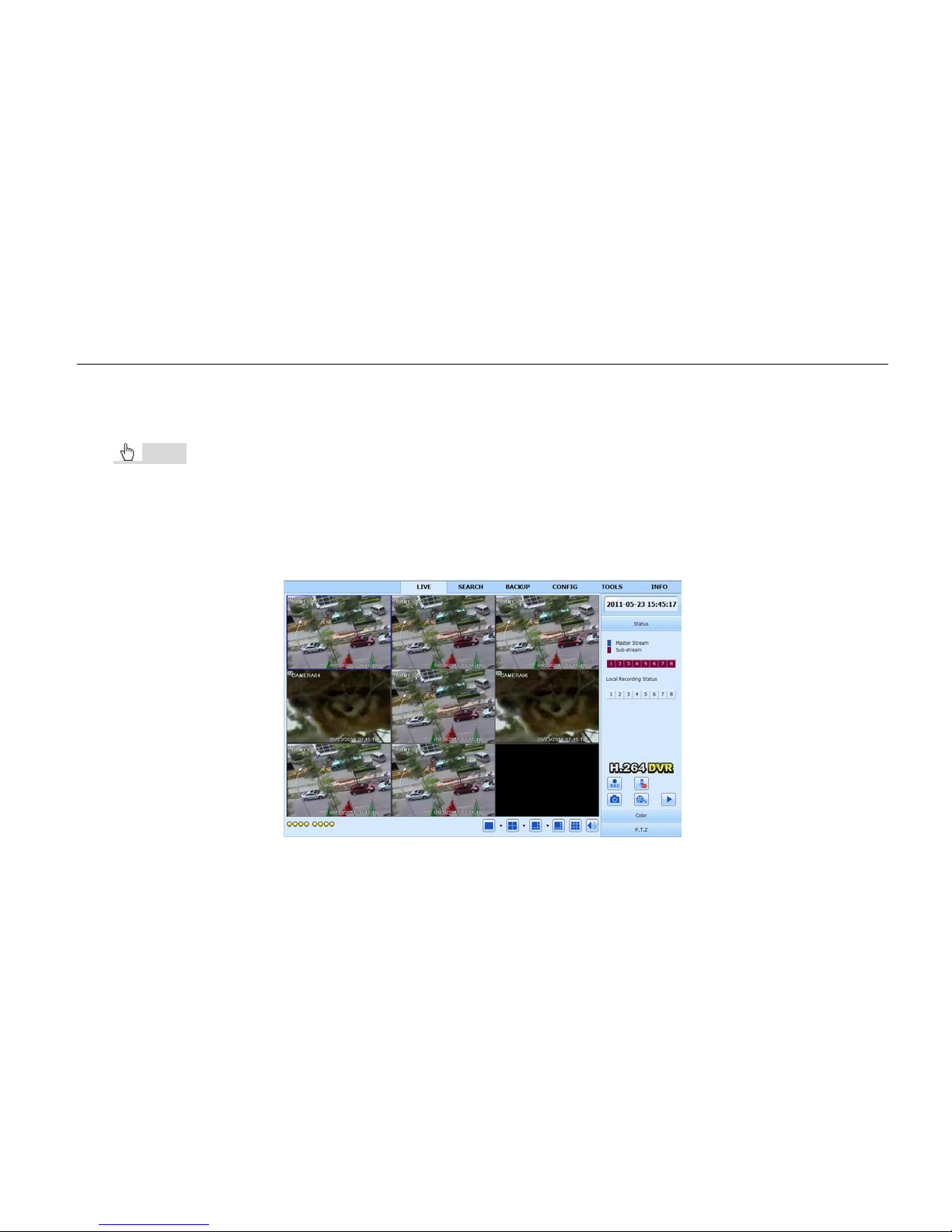
7 Remote Surveillance
7.1 IE Remote Surveillance
In order to view the DVR from a network, it must be connected to a LAN/WAN or internet. The network setup should be
done accordingly. Please refer to “4.6 Network Setup”. This DVR supports IE browser, on Windows XP, and Vista platform.
7.1.1 On LAN
Step 1: Enter into the DVR’s Main Menu Setup Network interface to input IP address, Subnet Mask, etc .If using
DHCP, please enable DHCP in both the DVR and the router.
Step 2: Enter Record Setup to set network v ideo parameters like resolution, frame rat e, etc.
Step 3: Open IE on a computer on the same network. Input the IP address of the DVR in IE and press enter.
Step 4: IE will download ActiveX components automatically. Enter the username and password in the subsequent window.
Notice: If HTTP port is not 80 and is a different number instead, user needs to add the port number after IP address.
For example, if set HTTP port as 82, user needs to input IP address like 192.168.0.25:82.
User name and password here are the same with that used on the DVR. The default is admin and 123456.
7.1.2 On WAN
There are two ways for the DVR to connec t to internet.
1. Connect the DVR to internet through router or virtual server
Step 1: Enter into the DVR’s Main Menu Setup Network interface to input IP address, Subnet Mask, etc. If using
DHCP, please enable DHCP in both the DVR and router.
Step 2: Forward IP address and port number in Virtual Server setup of the router or virtual server. Configure the firewall to
allow accessing the DVR. (If the user has enabled the UPnP function in both the DVR and router, he can skip this step.)
Step 3: If user wants to utilize dynamic domain name, please apply for a domain name in a DNS server (example:
www.no-ip.com, www.dyndns.com, etc.) supported by the DVR or router. Then add to the DVR or router.
Digital Video Recorder User Manual
55
Step 4: Open IE browser, input IP address, or dynamic domain name and enter. If HTTP port is not 80, add the port
number after IP address or domain name.
Step 5: IE will download ActiveX components automatically. A window pops up and asks for user name and password.
Input name and password correctly, and enter to view.
Notice: If you cannot download and install ActiveX, please refer to “Appendix A FAQ: Question 8”.
2. Connect the DVR to internet dir ect ly.
Step 1: Enter into the DVR’s Main Menu Setup Network interface to enable PPPoE and then input user name and
password received from your ISP. Next, click Apply. The DVR will connect to the server and would give a confirmation
message.
Step 2: When accessing the remote interface of DVR, user can input WAN IP to access directly (user can enter int o Main
menu Information Network inter face to check IP address). The browser will download ActiveX components.
Fig 7.1 View with IE Browser

Digital Video Recorder User Manual
56
7.2 Remote Surveillance through Apple PC
Note: Because the current plug-in version of client end just only suppo r t s 32-bit mode, the safari browser shall
start 32-bit mode. If the browser is the earlier MACOS version, the default set ting is 32-bit mode and the setting
can be skipped. The Setting steps are a s follows:
First: Right click safari icon
and select “Show in Finder”.
Second: Select Applications Right click “Safari. App” Select “Get Info”.
Third: Select “open in 32- bit mode”.
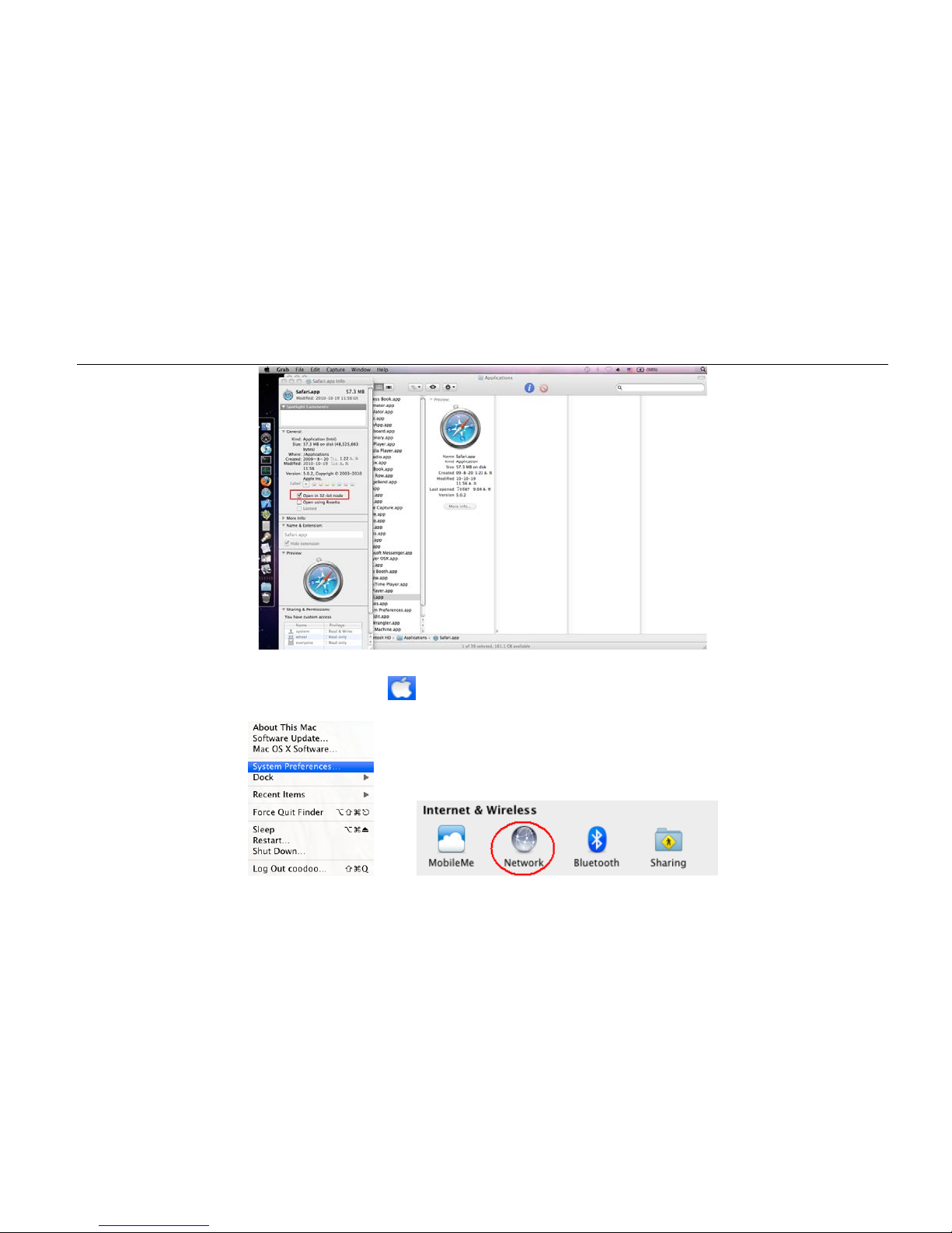
Digital Video Recorder User Manual
57
7.2.1 On LAN
Step 1: After starting Apple computer, click icon. The following window will pop up. Please select “System
Preferences” ”Internet &Wirel es s” click “Network”.

Digital Video Recorder User Manual
58
Step 2: Enter into Network interface and then click “Ethernet Connected” to check the internet connection of Apple PC.
Step 3: After acquiring the IP address, Subnet Mask, and so on, please enter into the DVR ’s Main Menu Setup
Network interface to manually input IP address, Subnet Mask, and Gateway acc ording to the configuration of PC. The
network segment should be the same as the PC. If using DHCP, please enable DHCP in the DVR and router.
Step 4: After finishing the above information, user can enter LAN IP and http port in the Safari browser. For example: input
http://192.168.1.100:81(her e 192.168.1.100 is LAN IP of DVR, 81 is the http por t of DVR). Click “ ”button and the
browser will download ActiveX components as shown below:

Digital Video Recorder User Manual
59
Step 5: Click
icon and the n select the ActiveX components. The welcome interface will be shown. Click “Continue”
”Install” button and the following window will pop up:
Input the name and password of Apple PC and then click “OK” to install the ActiveX components.
Step 6: After finishing installing the Active X components, please quit the Safari browser. Right click
icon on the
desktop and then select “Quit” button to quit the browser. Then restart Safari browser. Input the IP address and http port to
enter into the login interface of D V R .
7.2.2 On WAN
There are also two ways for DVR to connect to the Internet.
1. Connect the DVR to internet through router or virtual server
Step 1: The network setups are the same as step one to step four of point 1 on WAN of IE remote surveillance.
Step 2: Enter WAN IP and http port in the Safari browser to install the ActiveX components. The concrete steps are the
same as steps 5 and 6 of Chapter 7.2.1.
2. Connect the DVR to internet dir ectly.
Step 1: The network setups are the same as step one of point 2 on WAN of IE remote surveillance.
Step 2: Enter WAN IP and http port in the Safari browser to install the ActiveX components. The concrete steps are the
same as steps 5 and 6 of Chapter 7.2.1.

Digital Video Recorder User Manual
60
7.3 Remote Live Preview Interface
Fig 7.2 Remote Live Preview Interface
Symbol and function Definitio ns:
①
Channel indicator
②
Screen display mode
③
Volume
④
Snapping picture
⑤
Start manual record
⑥
Start IE record
⑦
Bidirectional talk
⑧
Playback
⑨
Color
⑩
PTZ control
⑪
Master/sub stream status

Digital Video Recorder User Manual
61
Note: Click
button to record manually and the record file will be saved in user ’s PC.
Screen display mode: Click the
icon beside t he scr een dis pl ay mod e and the channel selection dial o g will a ppe ar a s
below:
Take 8-channel DVR for example: User can tick off
channels 1-ch to 8-ch at random to display the live
pictures. 6 channels can be selected at most. Then click
OK button to confirm the setting.
Snap pictures:
Fig 7.3 Channel Select Dialog
Click “Snap”
icon and the system will automatically capture pictures and save those pictur es in the computer.
User should set up the save path for those picture in the Remote Preview interface Configuration Local configuration.
Color adjustment:
Drag the slide bar to adjust Brightness, Contrast, Hue, and Saturation. C li ck Default to reset them to original value.
Buttons
Description
Drag the scroll bar to adjust the brightness of the channel display
Drag the scroll bar to adjust the contrast of the channel display
Drag the scroll bar to adjust the saturation of the channel display
Drag the scroll bar to adjust the hue of the channel display
Click this button to recover th e default value of brightness, contr ast,
saturation and hue
Save the adjustment
PTZ control:
Please connect speed dome to the devic e via RS485 fir st. Make sure the protocol of the speed dome is s upported by the

Digital Video Recorder User Manual
62
device and set the relative parameters manually. User can control the dome up, down, right, left or stop rotating on Control
Center, adjust rotation speed, Iris and zoom, focus on the dome, and set the presets, etc.
Buttons definition:
Buttons
Description
means the dome rotate up. means the dome rotate up left.
means the dome rotate up right. means the dome rotate down.
means the dome rotate left down. means the dome rotate right
down.
means the dome r otate left. means the dome rotate
right. means the dome stop rotating.
Drag the scroll bar to adjust rotating speed of the dome.
'Iris' button. Click
button near 'Iris' button to increase light of the
dome. Click
button near 'Iris' button to decrease light of the
dome.
'Zoom' button. Click
button near 'Zoom' button to zoom in the
locale picture of this camera. Click
button near 'Zoom' button to
zoom out the locale picture of this camera.
'Focus' button. Click
button n ear 'Focus' button to have long
focus. Click button near 'Focus' button to have short focus.
Go to the Preset
Select and do auto cruise
Track
Auto scan
Wiper button

Digital Video Recorder User Manual
63
Light button
Click the right mouse on the live interface and a pull-down menu will appear like in Fig 7.4.
Fig 7.4 Right Key Sub Menu
Stream: This DVR supports master stream and sub stream. Master stream has higher frame rate, max 30 FPS (NTSC)/25
FPS (PAL) for every channel, but it needs higher network bandwidth simultaneously. Sub-stream has low frame rate, max
7 FPS (NTSC)/6FPS (PAL) for every channel. It requires low network bandwidth. Therefore, users can select the stream
according to their bandwidth.
All to master/sub stream: Set all channel to master stream or sub stream.
Enable audio: Enable or dis-enable audio.
Full screen: The live preview picture will display with full screen and the tool bar will be hidden. Double click left mouse or
click right mouse to return.
Zoom in: Single channel large screen electronic amplification.

Digital Video Recorder User Manual
64
7.4 Remote Playback & Backup
7.4.1 Remote playback
Click button to enter into record playback interface. Refer to Fig 7.5.
Select the record date and channels. Double-click the file name in the recorded file list box. User can play that file and
preview the picture.
Fig 7.5 Play Record File Interface
This DVR supports remote time search, event search, and file management.

Digital Video Recorder User Manual
65
By Time Search:
Step1: Enter into Search time search. Refer to Fig 7.6.
Fig 7.6 Time Search Interface
Step 2: Click “Search” button. The recorded data will be displayed in the data information list box. The highlighted date in
area ② means there is recorded data. Click those data and select the channels in area ③.
Step 3: User can set the data playing time and display mode in area ① as required.
Step 4: Select certain item from the data information list box and click “play” button to playback.
Step 5: Click the relevant buttons in the interface. User can do some operations such as: fast forward, pause, change
channel mode, research, etc. Refer to Fig 7.7.

Digital Video Recorder User Manual
66
Fig 7.7 Time Search Playback
By Event Search:
Step 1: Enter into Search event search. Refer to Fig 7.8.

Digital Video Recorder User Manual
67
Fig 7.8 Event Search Interface
Step 2: Click t he highlighted date and select channels and then tick off the event type: motion and sensor. Click “search”
button.
Step 3: The events will be displ ayed in the event list box. Double-click certain item to playback.
File Management
Step1: Enter into Search file management. Refer to Fig 7.9.

Digital Video Recorder User Manual
68
Fig 7.9 File Management Interface
Lock: Select certain file item in the file lis t box. Click “Lock” button to lock this file that cannot be deleted or overlaid.
Unlock: Select a locked file and click “unlock” button to unlock this f il e.
Delete: Select an unlock file and click “delete” button to delete this file from file list.
7.4.2 Remote Backup
Click Backup button to enter into backup interf ac e. Refer to Fig 7.10.

Digital Video Recorder User Manual
69
Fig 7.10 Remote Backup Interface
Step 1: Select channel and set the start and end time. Then click “search’ button to display the file information in the file list
box.
Step 2: Selec t back u p fi les and click “browse” button to set the save path. Then click “bac k up” button to start backup. The
backup files will be saved on user’s PC.
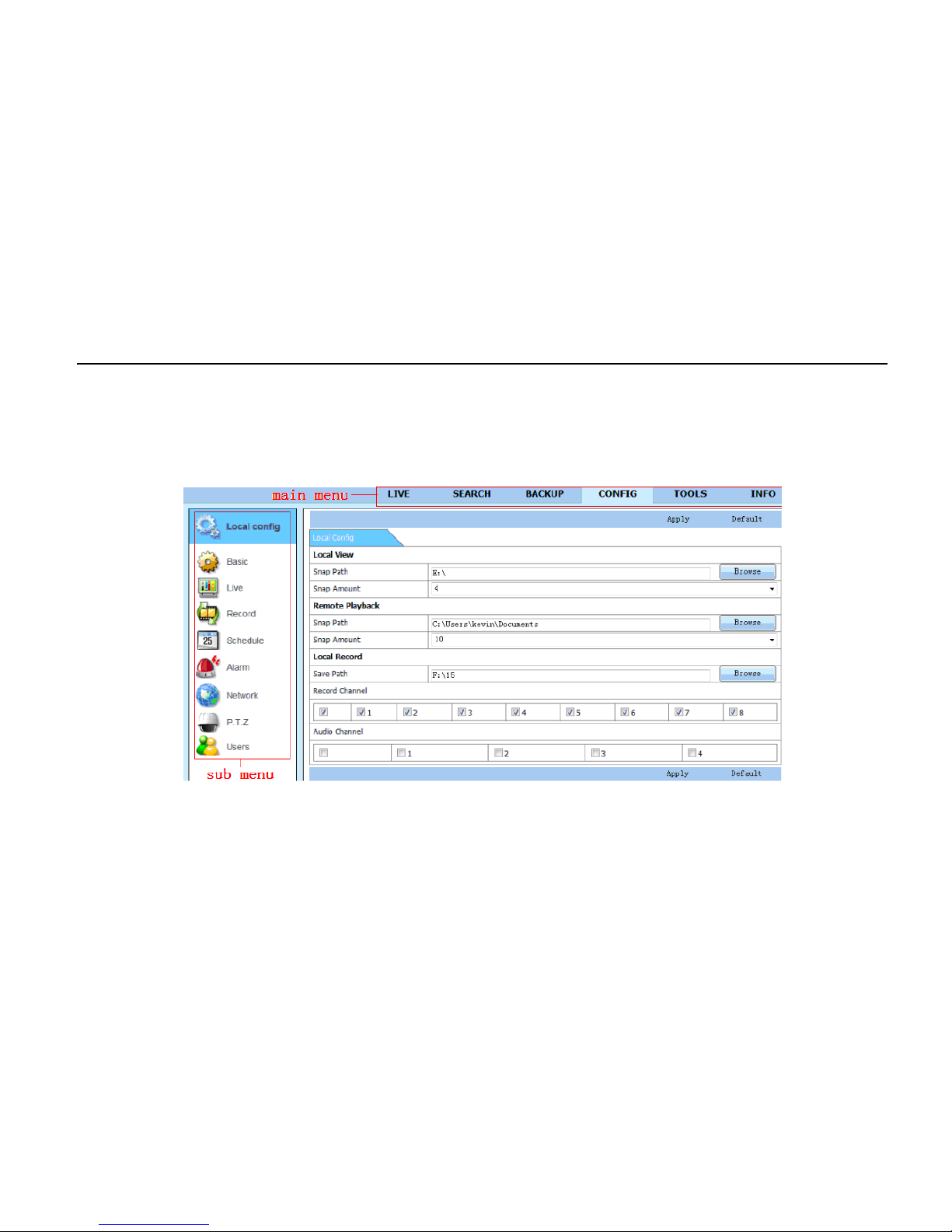
Digital Video Recorder User Manual
70
7.5 Remote System Configuration
User can remotely setup the parameters of the device. Functions of remote configurations include: basic configuration, live
configuration, record config uration, schedule configuration, alarm configuration, network configur ation, PTZ configuration,
and user configuration. User s hould select an item in the menu list on the left first and then setup the relative parameters.
When one user sets up parameters of a c ertain item, others cannot set it up. Click Config to enter into the belo w interface
like in Fig 7.11.
Fig 7.11 Remote Menu Setup
The sub menu lists and the options in every item are similar with those on the DVR. Please refer to Chapter 3 “Main Menu
Setup Guide” for more details. Click “Apply” button to save the above settings. Click “default” button to recover the original
settings.

Digital Video Recorder User Manual
71
Appendix A FAQ
Q1. Why can’t the DVR start after being connected to the power?
a. The adapter has been damaged. Please change an adapter.
b. The power of the adapter is not enough. Please r emove the HDD to check.
c. Hardware problem.
Q2. There is no menu output or only has live image display.
a. Check whether other devices can display menu or long press ESC key to wait for login dialog box to appear.
Q3. There’s indicator of the DVR lights, but no output. Why?
a. The power of the adapter is not enough. Please r emove the HDD or change an adapter to tr y.
b. The video format of the DVR is different from that of the monitor.
c. Connection problem. Please check the cable and the ports of monitor and DVR.
Q4. Why are no images displayed on parts or all of the channels of the DVR?
a. Connection problem. Please check the cable and the ports of camera and DVR.
b. Camera problem. Please check t he cameras.
c. The video format of the DVR is different from that of the cameras. Please change DVR system format.
Q5. Cannot find HDD
a. The power of the adapter is not enough. Please c hange an adapter to try.
b. Connection problem. Please check the power and data cables.
c. The HDD is damaged. Change a new one.

Digital Video Recorder User Manual
72
Q6. Cannot record
a. Don't format HDD. Please format it manually first.
b. Don't enable record function or set up incorrectly. Please refer to Chapter 5 “Record Search & Playback and Backup”.
c. HDD is full and does not enable recycle function. Please refer to “4.3 Record Configuration”. Change to a new HDD or
enable recycle.
d. The HDD is damaged. Change a new one.
Q7. Cannot use mouse
a. Wait 1-2 minutes after mouse is connected.
b. Not detected. Plug/unplug several times.
c. The mouse is incompatible. Please change to another mouse.
Q8. Cannot download ActiveX components
a. IE browser blocks ActiveX. Please follow the setup below.
① Open IE browser. Click Tools → Internet Options
② Select Security → Custom Level . Refer to Fig 8.1.
③ Enable all the sub options under “ActiveX controls and plug-ins”. Refer to Fig 8.2.
④ Click ok to finish setup.
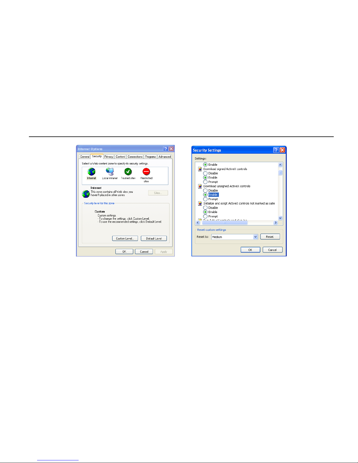
Digital Video Recorder User Manual
73
b. Other plug-ins or anti-virus blocks ActiveX. Please uninstall or close them.
Fig 8.1 Fig 8.2
Q9: How to deal with when DVR starts and displays “please wait…” all the time
First possible reason: Hard-disk cable and data cable are not connected well.
Solution: Please check the connection of hard-disk cable and data cable and make sure they are connected well. If it still
doesn’t work, please unplug them and then try re-plugging again.
Second possible reason: It is forced to stop because hard disk has disabled track, which causes the system to check the
hard disk.
Solution: Change to another new hard disk or reformat the broken one.

Digital Video Recorder User Manual
74
Q10: How to input pass word and digital numbers
The method to input password and digital numbers is to click the box behind password or items. A small keyboard will
appear. Please select numbers or letters to input (the initial password is 123456), or you can use the dig i tal ke ys in the
front panel.
Q11: Why is the hard disk used in a DVR identifying it as a new hard disk if it was directly used with another
similar type DVR? And why must we format it again?
When DVR only uses one hard disk, the hard disk removed from one to another similar type DVR can work normally
without format. However, when a DVR adds a new hard disk, it will identify the hard disk as a new one and inquire whether
to format, whether this hard disk was used or not in another sim ilar type of DVR before. In this condition, it can be used
normally after being formatted according to the guide. If there’s two or more hard disks used in different DVRs, when used
in another DVR with a similar type, they will be identified to be two or more new hard disks, and all of them need to be
formatted. In general, please do not try using more disks removed from different D V R s into another one in case the data
becomes lost.
Q12: What are the minimum configurations of PC for client connecting?
PC Module
Parameters
CPU
Intel Celeron 2.4G
Motherboard
Intel 845
HDD
80G
RAM
512M
VGA
NVIDIA GeForce MX440/FX5200; ATIRADEON 7500/X300
OS
Windows 2000(SP4 above) /Windows XP(SP2 above) /VISTA
DirectX
9.0

Digital Video Recorder User Manual
75
Q13: How to handle a situation when codec control is blocked to install in VISTA or Win7 system?
If user gets this problem, there may be two ways to fix it:
a. Enter Control Panel User Account and Family Safety User Account Control (refer to below picture). Click Turn User
Account on or off. Cancel using User Account Control (UAC) to help protec t your computer.
b. Right click IE browser (refer to Fig 13.2). Select Run as administrator to run browser.

Digital Video Recorder User Manual
76
Appendix B Calculate Recording Capacity
User can calculate the size of hard di s k according to the saving time and DVR r ecording settings. The DVR uses fixed
video bit rate. The table below is the details at different settings.
Video Format Resolution
Total Frame Rate
(FPS)
Video Quality Bit Rate (kbps) Used Space(MB/h)
NTSC CIF 30
Highest
1M
465
Higher
768k
297
Medium
512k
230
Low
384k
173
Lower
256k
115
Lowest
128k
56
PAL CIF 25
Highest
1M
466
Higher
768k
295
Medium
512k
235
Low
384k
175
Lower
256k
112
Lowest
128k
56.4
The calculation format is: Total Recording Capacity = Used space per hour (MB/h) (coverage rate of hard disk) ×
recording time (hour) × channel numbers.
For instance, one customer uses NTSC cameras, set resolution to CIF, video quality to Lowest, frame rate to 30 fps for
enabling total 8 channels. He wants the unit to record continuously in a month. Below is the calculation:
Total Recoding capacity =56 (MB/h) X 24 (hrs/day) X 30 (days) X 8 (channels) = 322560 (MB) ≈ 323 (GB)
Therefore, customer needs to install just one SATA HDD with 323GB because it can record for almost one month.

Digital Video Recorder User Manual
77
Appendix C Compatible Devices
1. Compatible USB drive (though we do not guarantee full compatibility)
Brand
Capacity
SSK
512MB, 1G, 2GB
Netac
4GB
Kingston
2GB
Aigo
2GB
Smatter vider
1GB
SanDisk
4GB
2. Compatible HDD list (though we do not guarantee full com patibility)
Brand
Capacity
Seagate Barracuda LP ST3200542AS
2TB
Seagate Barracuda 7200.11 ST31500341AS
1.5T
Seagate SV35.3 ST31000340SV
1T
Seagate Pipeline HD.2
500G
Seagate Barracuda 7200.10
320G
Seagate Barracuda 7200.10 ST3250310AS
250G
Seagate Barracuda 7200.11 ST3160813AS
160G
Seagate Barracuda 7200.10 ST380815AS
80G
Maxtor Diamondmax 21 STM3160215AS
160G
HITACHI Deskstar HDS721616PLA380
160G
HITACHI Deskstar
80G
WD WD1600JS
160G
Samsung HD161HJ
160G

Digital Video Recorder User Manual
78
Appendix D 4-CH Specifications
Compression format
Standard H.264 Baseline
Video output
Composite: 1.0V p-p / 75Ω BNC×2, VGAX1
Video input
Composite: 1.0V p-p / 75Ω BNC×4
VGA Resolution
1280*1024 / 1024*768 / 800*600
Record Resolution 352*240/704*480 (NTSC), 352*288/704*576 (PAL)
Display Frame Rate
120FPS (NTSC), 100FPS (PAL)
Record Frame Rate
120FPS (NTSC), 100FPS (PAL)
Audio input
-8dB~22k, RCA X 4
Audio output
-8DB~92dB, RCA X 1
Alarm input
NO or NC 4CH
Alarm output: 1CH
Record Mode
Manual / Sensor / Timer / Motion det ec tion
Simplex / Duplex / Triplex Pentaplex
Network Interface RJ-45 (LAN, INTERNET)
PTZ control
YES
Communication interface
RS485, USB 2.0 x 2 (one for backup, an other for USB mouse)
Disk info
1 SATA (not included)
Remote controller YES
Power supply 12V3A
Temperature 0℃-50℃
Humidity
10%-90%
Average Operating Power (Excluding HDD) ≤30W

Digital Video Recorder User Manual
79
Appendix E 8-CH Specifications
Compression format
Standard H.264 Baseline
Video output
Composite: 1.0V p-p / 75Ω BNC×2, VGAX1
Video input
Composite: 1.0V p-p / 75Ω BNC×8
VGA Resolution
1280*1024 / 1024*768 / 800*600
Record Resolution 352*240/704*480 (NTSC), 352*288/704*576 (PAL)
Display Frame Rate 240FPS (NTSC), 200FPS (PAL)
Record Frame Rate
240FPS (NTSC), 200FPS (PAL)
Audio input
-8dB~22k, RCA X4
Audio output
-8DB~92dB, RCA X1
Alarm input NO or NC 8CH
Alarm output:
1CH
Record Mode
Manual / Sensor / Timer / Motion det ec tion
Simplex / Duplex / Triplex
Pentaplex
Network Interface
RJ-45 (LAN, INTERNET)
PTZ control
YES
Communication interface
RS485, USB2.0 x 2 (one for backup, another for USB mouse)
Disk info
1 SATA (not included)
Remote controller
YES
Power supply
12V3A
Temperature 0℃-50℃
Humidity
10%-90%
Average Operating Power (Excluding HDD) ≤30W
 Loading...