

Page 1

D I V I G R A P H ( P T Y ) L T D
VP Series 2000 User Guide
EVR-VPXDOC-0036-100
Version 1.01
16 November 2017
Proprietary & Confidential – Copyright © 2017 Divigraph (Pty) Ltd. All Rights Reserved
Non-disclosure
This document is the property of Divigraph (Pty) Ltd trading as DIVIGRAPH and shall not be copied, shown or communicated to a third
party without the consent of the owner. Receiving this document by any individual, organisation, entity or their employees or
representatives (herein the Receiver) constitutes the Receiver’s agreement that they are acquainted with the provisions of the
Protection of Information Act (Act No.84 of 1982) and in particular with the provisions of section 4 of the Act.
The Receiver realises it is guilty of an offence should it disclose any information at its disposal on account of this document, to anyone
other than:
• a person lawfully entitled to it; or
• a person to whom the Receiver is in duty bound to disclose it in the interests of the Republic; or
• a person to whom the Receiver has been authorised to disclose such information – by DIVIGRAPH or another official
Copyrights
Under the copyright laws, this document may not be reproduced or transmitted in any form, electronic or mechanical, including
photocopying, recording, storing in an information retrieval system, or translating, in whole or in part, without the prior written consent of
DIVIGRAPH.
Trademarks
Product and company names mentioned herein are trademarks or trade names of their respective companies.
Document Control
Document is uncontrolled unless otherwise marked; uncontrolled documents are not subject to update notification.
authorised by DIVIGRAPH.
DIVIGRAPH – PostNet Suite # 72 – Private Bag X7 – Chempet – 7442
Tel.: +27 (21) 551-1836 | Fax.: +27 (86) 689-5732
email: info@evrika.co.za | web: www.divigraph.com
Page 2
EVR-VPXDOC-0036-100 VP Series 2000 User Guide
Title
Pages
Document ID
Version
Status
Date
Comments
Document Information
VP Series 2000 User Guide
33
16 November 2017
EVR-VPXDOC-0036-100 1.01 Released
Version 1.01 Proprietary & Confidential – Copyright © 2017 Divigraph (Pty) Ltd. All Rights Reserved Page 2 / 33
Page 3

EVR-VPXDOC-0036-100 VP Series 2000 User Guide
Table of Contents
1 Introduction ..................................................................................................................................... 7
1.1 Document Purpose ................................................................................................................. 7
1.2 Document Scope .................................................................................................................... 7
1.3 References.............................................................................................................................. 7
1.4 Terms and Definitions ............................................................................................................. 8
1.4.1 Abbreviations ................................................................................................................................. 8
1.4.2 Terminology ................................................................................................................................... 8
1.5 Support ................................................................................................................................... 8
2 General Safety ................................................................................................................................ 9
2.1 Receiving Inspection ............................................................................................................... 9
2.2 Safe Handling ......................................................................................................................... 9
2.3 Safety Labels and Markings ................................................................................................... 9
2.4 Hazardous Materials ............................................................................................................... 9
2.5 Installation, Operation and Maintenance .............................................................................. 10
2.5.1 Installation .................................................................................................................................... 10
2.5.2 Operation ..................................................................................................................................... 10
2.5.3 Maintenance ................................................................................................................................ 10
2.6 Disposal ................................................................................................................................ 11
2.6.1 Product Replacement and Failure Analysis ................................................................................. 11
2.6.2 Hazardous Material Disposal ....................................................................................................... 11
2.6.3 Recycling Facilities ...................................................................................................................... 11
2.7 Certification ........................................................................................................................... 11
2.8 Cyber Security ...................................................................................................................... 11
3 Radio and Electromagnetic Compatibility ..................................................................................... 12
3.1 Canada and USA .................................................................................................................. 12
4 VP Series 2000 Components ....................................................................................................... 13
4.1 Field Device Configurations .................................................................................................. 13
4.1.1 Integrated Vibration and Temperature Monitoring ....................................................................... 13
4.1.2 Repeaters .................................................................................................................................... 13
4.2 Electrical Cells ...................................................................................................................... 15
4.3 Mounting Adaptors ................................................................................................................ 16
4.4 Installation Tools ................................................................................................................... 17
4.5 Software ................................................................................................................................ 18
4.6 Configuration Interface ......................................................................................................... 18
5 Provisioning .................................................................................................................................. 19
Version 1.01 Proprietary & Confidential – Copyright © 2017 Divigraph (Pty) Ltd. All Rights Reserved Page 3 / 33
Page 4

EVR-VPXDOC-0036-100 VP Series 2000 User Guide
5.1 Device Join Behaviour .......................................................................................................... 19
5.2 Direct Connection Provisioning ............................................................................................ 19
5.3 OTA Provisioning .................................................................................................................. 20
5.4 Unprovisioning ...................................................................................................................... 20
6 Hardware Installation .................................................................................................................... 21
6.1 Mounting Guidelines ............................................................................................................. 21
6.2 Hardware Installation Best Practices .................................................................................... 22
7 Configuration ................................................................................................................................ 23
7.1 Capability Files ..................................................................................................................... 23
7.2 Data Publishing ..................................................................................................................... 23
7.2.1 Modbus ........................................................................................................................................ 23
7.2.2 OPC ............................................................................................................................................. 23
8 Operation ...................................................................................................................................... 25
8.1 Measurements ...................................................................................................................... 25
8.1.1 Temperature ................................................................................................................................ 25
8.1.2 Acceleration ................................................................................................................................. 25
8.1.3 Velocity ........................................................................................................................................ 25
8.2 Parameter Publishing ........................................................................................................... 26
9 Maintenance ................................................................................................................................. 27
9.1 Cleaning ................................................................................................................................ 27
9.2 Disassembly.......................................................................................................................... 27
9.3 Assembly .............................................................................................................................. 28
9.4 Device Inspection ................................................................................................................. 28
9.4.1 O-Ring Inspection ........................................................................................................................ 28
9.4.2 E-Module Inspection .................................................................................................................... 29
9.4.3 Cell Inspection ............................................................................................................................. 29
9.4.4 Sensor Body Inspection ............................................................................................................... 31
9.5 Cell Replacement ................................................................................................................. 31
9.6 Firmware Updates ................................................................................................................ 32
9.7 Device Reset ........................................................................................................................ 32
10 Security Hardening Guidelines ..................................................................................................... 33
10.1 System Hardening ................................................................................................................ 33
10.2 Recommendations for Improved Availability and Reliability ................................................. 33
10.2.1 Cell Life .................................................................................................................................... 33
10.2.2 Network Redundancy .............................................................................................................. 33
Version 1.01 Proprietary & Confidential – Copyright © 2017 Divigraph (Pty) Ltd. All Rights Reserved Page 4 / 33
Page 5

EVR-VPXDOC-0036-100 VP Series 2000 User Guide
Tables
Table 1 - Abbreviation Definitions ........................................................................................................... 8
Table 2 - Terminology and Definitions .................................................................................................... 8
Version 1.01 Proprietary & Confidential – Copyright © 2017 Divigraph (Pty) Ltd. All Rights Reserved Page 5 / 33
Page 6

EVR-VPXDOC-0036-100 VP Series 2000 User Guide
Figures
Figure 1 VP2000 Components .............................................................................................................. 13
Figure 2 - Cell - Xeno XL-205F ............................................................................................................. 15
Figure 3 - Cell - Tadiran TL-5930 .......................................................................................................... 15
Figure 4 - Mounting Adaptor - M6 ......................................................................................................... 16
Figure 5 - Mounting Adaptor - M8 ......................................................................................................... 16
Figure 6 - Mounting Adaptor - Mounting Pad ........................................................................................ 16
Figure 7 - Mounting Adaptor - 1/4-28 UNF ........................................................................................... 16
Figure 8 - Mounting Adaptor - 10-32 UNF ............................................................................................ 16
Figure 9 - Mounting Adaptor - 3/8-24 UNF ........................................................................................... 16
Figure 10 - Mounting Adaptor - Tri-Axial Alignment Mount ................................................................... 16
Figure 11 - Installation Tools - Cell Installation Tool ............................................................................. 17
Figure 12 - Installation Tools - Straight Hook Spanner ......................................................................... 17
Figure 13 - Installation Tools - Tri-Axial Mount Spanner ...................................................................... 17
Figure 14 - VP Series 2000 - USB Configuration Interface .................................................................. 18
Figure 15 - VP Series 2000 - Minimum Installation Clearance ............................................................. 21
Figure 16 - VP Series 2000 - Fall Protection Hole ................................................................................ 21
Figure 17 - VP Series 2000 - Cemented Pad Mount ............................................................................ 22
Figure 18 - VP Series 2000 - Tri-Axial Alignment Mount ...................................................................... 22
Version 1.01 Proprietary & Confidential – Copyright © 2017 Divigraph (Pty) Ltd. All Rights Reserved Page 6 / 33
Page 7

EVR-VPXDOC-0036-100 VP Series 2000 User Guide
1 Introduction
VP Series 2000 products include a range of ISA100.11a compliant wireless nodes for use with
ISA100.11a wireless networks. The product range includes the following components:
• VP Series 2000 Tri-axial ISA100.11a Wireless Accelerometer
• VP Series 2000 ISA100.11a Repeater
• Lithium cell
• Mounting hardware
• Installation tools
• Device docking station
VP Series 2000 ISA100.11a Wireless sensors measure vibration as well as temperature and are
capable of acting as ISA100.11a repeaters in ISA100.11a compliant wireless networks. They are
intended for use in condition monitoring applications to optimise the reliability of low- and mediumcriticality machines, achieve maintenance cost reductions, shrink the number of unplanned machine
failures and increase machinery life. Machinery applications include, but are not limited to:
• Agitators
• Compressors
• Ball mills
• Blowers
• Centrifuges
• Cooling tower fans and pumps
• Motors
• Gearboxes
• Small reciprocating compressors
• Small hydro and steam turbines
1.1 Document Purpose
The purpose of this document is to describe how to set up VP Series 2000 ISA100.11a Field Devices
for use with ISA100.11a wireless networks as well as to familiarise the user with applicable wireless
node features. The guide describes the essentials of deploying a successful field installation in
addition to describing some radio frequency concepts together with some guidelines to aid the
understanding of the requirements when planning a wireless sensor network installation for a site.
1.2 Document Scope
The scope of this document is limited to use of VP Series 2000 ISA100.11a wireless nodes. This user
guide does not include details with regard to the installation and configuration of specific vendor
ISA100.11a wireless network infrastructure. Vendor specific Application Notes may be available,
alternatively refer to the specific vendor documentation for additional details.
Note!
This guide does not contain all the information to operate and maintain the product. Refer to
referenced documentation or contact the product supplier for additional information.
1.3 References
Refer to the following documents for additional information:
• VP Series 2000 Product Data Sheet
•
VP Series 2000 Software User Guide
Version 1.01 Proprietary & Confidential – Copyright © 2017 Divigraph (Pty) Ltd. All Rights Reserved Page 7 / 33
Page 8
EVR-VPXDOC-0036-100 VP Series 2000 User Guide
1.4 Terms and Definitions
Terms and Definitions include descriptions of terms used in the document, abbreviation definitions,
etc.
1.4.1 Abbreviations
AP Access Point
BBR Back Bone Router
CF Capabilities File
CS Control System
DCS Distributed Control System
DD Device Descriptor
FD Field Device
GW Gateway
ICSS Integrated Control and Safety System
OPC OLE for Process Control
OTA Over the Air
RF Radio Frequency
TIL Technical Information Letter
USB Universal Serial Bus
WCI Wireless Conformance Institute
WSN Wireless Sensor Network
Table 1 - Abbreviation Definitions
1.4.2 Terminology
Access Point A device that provides a physical interface between a wireless network and
gateway.
Field Device A node that has I/O or routing capabilities or both.
Gateway A device that provides a link between Ethernet and other types of networks
such as ISA100.11a.
Modbus RTU Serial Communication based Modbus Protocol.
Modbus TCP TCP based Modbus client/server Protocol.
Node An element of an ISA100.11a wireless network e.g. a FD or AP.
OPC A generic method of publishing field device data for use by measurement,
automation and control systems.
OPC DA OPC Data Access - a simple, platform dependant OPC protocol.
OPC UA OPC Unified Architecture - a platform independent OPC protocol.
Table 2 - Terminology and Definitions
1.5 Support
For additional support, contact:
Divigraph (Pty) Ltd
2G Matix Build, Bridgeway Road
Cape Town
7441
South Africa
www.divigraph.com
Version 1.01 Proprietary & Confidential – Copyright © 2017 Divigraph (Pty) Ltd. All Rights Reserved Page 8 / 33
Page 9

EVR-VPXDOC-0036-100 VP Series 2000 User Guide
2 General Safety
This section addresses some issues around personal safety in working with the product, product
safety to prevent damage and environmental safety for a more global approach.
2.1 Receiving Inspection
The product should be visually inspected for obvious shipping damage. If shipping damage is
detected, a claim should be submitted to the applicable carrier and a copy of the claim should be
submitted to the applicable product supplier.
Note!
The product is shipped without a Lithium cell.
2.2 Safe Handling
There are several things that can be done to maximise the value provided by the product. Proper
handling of components, best practices for installation and diligent inspection procedures will prolong
the service life of the product. Additionally, procedures for dealing with system components replaced
by maintenance are detailed to allow compliance with regulations relating to electronic waste.
2.3 Safety Labels and Markings
Labels and markings are provided on the product to guide system integrators in the process of
choosing appropriate interface equipment, determining safe use conditions and identifying
recommended installation procedures. The formats of these markings are governed by the standards
that dictate the safe use and environmental compliance in a variety of regions and regulated settings.
The areas where the product and associated equipment are certified for use are marked on a
prominent part of the product. The information includes the name and type of the original
manufacturer, serial number of the product, the certificate number and issuing body for hazardous
area approvals as well as the Ex marking to indicate the methods of protection employed by the
product.
The product will be marked with the CE logo to indicate compliance with electromagnetic compatibility
standards and Explosion Atmosphere standards required of industrial instrumentation for use in the
European Union.
2.4 Hazardous Materials
The product makes use of a Lithium cell which shall be disposed of by the end user in accordance
with applicable statutory and regulatory as well as site specific safety requirements. Do not crush the
product as this may cause the Lithium cell to rupture.
Version 1.01 Proprietary & Confidential – Copyright © 2017 Divigraph (Pty) Ltd. All Rights Reserved Page 9 / 33
Page 10

EVR-VPXDOC-0036-100 VP Series 2000 User Guide
2.5 Installation, Operation and Maintenance
Refer and adhere to applicable statutory and regulatory as well as site specific safety requirements
when installing, operating or maintaining the product.
Installations and maintenance tasks performed in potentially hazardous areas must be performed only
after the area has been verified to be free of hazardous materials, atmospheres and conditions.
Warning!
The following situations could cause a spark enough to ignite an explosion:
o Potential of electrostatic discharge on plastic components.
o Removal or placement of an energized connection.
POTENTIAL ELECTROSTATIC CHARGING HAZARD - The equipment shall only be cleaned
with a damp cloth when deployed in a hazardous area.
2.5.1 Installation
The original supplier takes no responsibility for any loss or damage caused by not adhering to
applicable safety requirements, the installation of the product in any manner other than described in
this document or due to incorrect or negligent installation as per the methods described in this
document and associated documents.
2.5.2 Operation
Routine inspection procedures should be followed to ensure the continued safe operation of the
product. If any damage is observed during routine inspections, the product should be removed for
maintenance as soon as possible. If the product is used in a hazardous area, it should be removed
without delay if damaged.
Warning!
Do not operate a damaged product in a hazardous area.
Report any leakage from the product to the appropriate responsible person as soon as
possible and follow applicable hazardous material procedures.
The protection provided by the equipment may be impaired if the equipment is used in a
manner not specified by the manufacturer.
2.5.3 Maintenance
The product requires minimal routine operational maintenance other than cleaning the area around
the product to ensure safe and reliable operation as well as to prolong the service life of the product. If
the Lithium cell in the product requires replacement, follow applicable hazardous material procedures
to replace and dispose of it.
Version 1.01 Proprietary & Confidential – Copyright © 2017 Divigraph (Pty) Ltd. All Rights Reserved Page 10 / 33
Page 11

EVR-VPXDOC-0036-100 VP Series 2000 User Guide
2.6 Disposal
Customers or third parties who are not member states of the European Union are solely responsible
for diligent product disposal at the end of its useful life. No person, firm, corporation, association or
agency shall dispose of the product in such a way that is in violation of any applicable international,
federal, state or local regulations. The original supplier is not responsible for product disposal at the
end of its useful life.
Warning!
Ensure that the Lithium cell has been removed from the product prior to disposal.
Dispose of Lithium cells as required by local and international law.
2.6.1 Product Replacement and Failure Analysis
The web site for the original supplier offers contact information for a variety of tasks. By visiting the
website, the process for returning parts under warranty can be initiated and failure analysis can be
requested.
2.6.2 Hazardous Material Disposal
Lithium cells shall be disposed of separately as per applicable hazardous material disposal
procedures in accordance with applicable international, federal, state or local regulations.
2.6.3 Recycling Facilities
Decommissioning of instrumentation should endeavour to minimise the impact of the waste created
by disposal of system material. Refer to local or regional waste removal administration to collect
information on proper material collection, re-use and recycling.
2.7 Certification
The VP Series 2000 product range is designed for use in hazardous areas and complies with
applicable rules statutory and regulatory requirements. Refer to the product data sheet for a listing of
certifications for the VP Series 2000 ISA100.11a sensor products.
2.8 Cyber Security
The VP Series 2000 makes use of the VP Series 2000 PC software application along with a USB
device docking station for provisioning and firmware update purposes. VP Series 2000 devices
contain measures to help reduce cyber security risks, but may not eliminate all risk. As is common
practice with all computers, it is strongly recommended to implement additional cyber security
protection measures such as user access controls, anti-virus scanning, implementing all updates,
encryption and PC management software. These recommended measures are at the end user’s
discretion, and are their responsibility. Some residual risk may remain.
Version 1.01 Proprietary & Confidential – Copyright © 2017 Divigraph (Pty) Ltd. All Rights Reserved Page 11 / 33
Page 12

EVR-VPXDOC-0036-100 VP Series 2000 User Guide
3 Radio and Electromagnetic Compatibility
3.1 Canada and USA
Cet appareil numérique de la classe A est conforme à la norme NMB-003 du Canada.
This Class A digital apparatus complies with Canadian ICES-003 and part 15 of the FCC Rules.
Operation is subject to the following two conditions: (1) This device may not cause harmful
interference, and (2) this device must accept any interference received, including interference that
may cause undesired operation.
Warning!
Changes or modifications not expressly approved by the manufacturer could void the user’s
authority to operate the equipment.
Version 1.01 Proprietary & Confidential – Copyright © 2017 Divigraph (Pty) Ltd. All Rights Reserved Page 12 / 33
Page 13

EVR-VPXDOC-0036-100 VP Series 2000 User Guide
4 VP Series 2000 Components
Cell Fastener
Sensor Body
Enclosure
Retainer
SM500
Figure 1 VP2000 Components
The VP Series 2000 range of products consists the components illustrated in Figure 1. The
components include the Sensor Body, Cell Retainer, SM500 e-module and Enclosure Retainer.
4.1 Field Device Configurations
VP Series 2000 field devices are available in tri-axial or uni-axial vibration monitoring and includes
temperature monitoring. A dedicated repeater field device is available in order to extend the wireless
network reach. Refer to the product data sheet for sensor ordering information.
4.1.1 Integrated Vibration and Temperature Monitoring
The VP2030 and VP2010 are field devices that contain tri-axial and uni-axial integrated sensors
respectively as well as a temperature sensor. They are capable of operating as ISA100.11a input
devices and routers. End users can set the sensor device roles depending on network requirements.
Refer to the applicable ISA100.11a network infrastructure vendor documentation for additional
information on how to enable or disable the sensor router role and sensor routing options.
Note!
Enabling the router role of a VP Series 2000 sensor will significantly affect cell life.
Warning!
VP Series 2000 sensors are intended for monitoring purposes only and should not be used in
control or safety systems.
4.1.2 Repeaters
Version 1.01 Proprietary & Confidential – Copyright © 2017 Divigraph (Pty) Ltd. All Rights Reserved Page 13 / 33
Page 14

EVR-VPXDOC-0036-100 VP Series 2000 User Guide
The NR1210 is an ISA 100.11a repeater which enables the expansion of an ISA100.11a wireless
network by providing a routing role. As a routing device, a repeater is able to extend the range of an
ISA100.11a compliant wireless network, provide routing redundancy or provide a routing option to a
sensor that has poor signal strength or quality or combination of both. Consider the use of this cell
powered repeater when a line powered IS100.11a access point or repeater is not practical.
Refer to the product data sheet for repeater ordering information.
Note!
VP Series 2000 repeaters should be used to extend a wireless sensor field or to provide
communication paths for devices in areas where the wireless network provides inadequate
coverage.
VP Series 2000 repeaters should not be used to extend the initial reach of a wireless network
router or to route a large number of devices through itself.
Warning!
VP Series 2000 repeaters are intended for monitoring purposes only and should not be used
in control or safety systems.
Version 1.01 Proprietary & Confidential – Copyright © 2017 Divigraph (Pty) Ltd. All Rights Reserved Page 14 / 33
Page 15

EVR-VPXDOC-0036-100 VP Series 2000 User Guide
4.2 Electrical Cells
A Lithium primary cell powers the VP Series 2000 sensors and repeaters. As such, applicable
precautions should be taken when installing, operating and maintaining these products.
Figure 2 - Cell - Xeno XL-205F
Figure 3 - Cell - Tadiran TL-5930
Lithium cells are not provided with the product and it is the responsibility of the end-user to source
and use only approved cells. The only cells approved:
• Tadiran SL-2780
• Tadiran TL-5930
• Tadiran TLH-5930
• Xeno XL205-F
Warning!
Use of any cell other than the models listed in the product data sheet will void the product
hazardous area certification.
Use of any cell other than the type listed may present a significant safety hazard.
Note!
Use of any cell other than the type listed in the product data sheet will void the product
warrantee.
Device performance and specifications are only valid if an approved cell is used.
The original supplier takes no responsibility for any loss or damage resulting from the use of
an unapproved electrical cell.
Version 1.01 Proprietary & Confidential – Copyright © 2017 Divigraph (Pty) Ltd. All Rights Reserved Page 15 / 33
Page 16

EVR-VPXDOC-0036-100 VP Series 2000 User Guide
4.3 Mounting Adaptors
Various mounting options can be used when installing VP Series 2000 devices. In some cases
mounting adaptors may be required to achieve the most effective mount. Mounting adaptors include:
Figure 4 - Mounting Adaptor - M6
Figure 5 - Mounting Adaptor - M8
Figure 6 - Mounting Adaptor - Mounting Pad
Figure 7 - Mounting Adaptor - 1/4-28 UNF
Figure 8 - Mounting Adaptor - 10-32 UNF
Figure 9 - Mounting Adaptor - 3/8-24 UNF
Figure 10 - Mounting Adaptor - Tri-Axial Alignment Mount
Refer to the product data sheet for mounting adaptor ordering information.
Version 1.01 Proprietary & Confidential – Copyright © 2017 Divigraph (Pty) Ltd. All Rights Reserved Page 16 / 33
Page 17

EVR-VPXDOC-0036-100 VP Series 2000 User Guide
4.4 Installation Tools
In order to simplify installation, the VP Series 2000 product range includes specialised installation
tools. These are available in a kit consisting of the following items:
• BT-10 Cell installation tool
• MT-20 Straight hook spanner
• MT-30 Tri-axial mount spanner
Figure 11 - Installation Tools - Cell Installation Tool
Figure 12 - Installation Tools - Straight Hook Spanner
Figure 13 - Installation Tools - Tri-Axial Mount Spanner
Refer to the product data sheet for installation tool ordering information.
Version 1.01 Proprietary & Confidential - Copyright © 2017 Divigraph (Pty) Ltd. All Rights Reserved Page 17 / 33
Page 18

EVR-VPXDOC-0036-100 VP Series 2000 User Guide
4.5 Software
VP Series 2000 devices can be configured, provisioned and firmware updates can be applied using
the VP Series 2000 software.
Refer to the VP Series 2000 Software User Guide for additional information.
4.6 Configuration Interface
An USB configuration interface is used to interface VP Series 2000 devices with the VP Series 2000
software.
Figure 14 - VP Series 2000 - USB Configuration Interface
Note!
Only use the supplied Identiv CLOUD 3700 F USB interface. Refer to the VP Series 2000
product data sheet for ordering information.
Refer to the product data sheet for USB configuration interface ordering information.
Version 1.01 Proprietary & Confidential - Copyright © 2017 Divigraph (Pty) Ltd. All Rights Reserved Page 18 / 33
Page 19

EVR-VPXDOC-0036-100 VP Series 2000 User Guide
5 Provisioning
Provisioning is a pre-installation step usually performed indoors in an equipment room or a similar
environment. This process requires both the hardware and software components.
Depending on the network infrastructure used, VP Series 2000 devices are either provisioned using a
node docking station (direct connection) or by means of “Over-The-Air” (OTA) provisioning. The
ISA100.11a network ID, ISA100.11a network security join key and ISA100.11a device tag values are
assigned during the provisioning process.
Each network infrastructure vendor has a unique provisioning process. Refer to the network
infrastructure vendor documentation for provisioning best practices.
5.1 Device Join Behaviour
VP Series 2000 devices periodically attempt to join an ISA100.11a network after power has been
applied. The period between join attempts is determined by a device sleep schedule. The sleep
schedule applies to both provisioning and provisioned network join attempts.
The VP will switch its receiver on for 45 seconds at a time to attempt a join. After reset, or after after a
full join the device transitions thought the follow five power states.
1) Attempts to join 3 times during the first 5min.
2) Attempts to join every 5m45s during 5min to 40min after reset.
3) Every 20min during 40min to 3h30min after reset.
4) Every 45min during 3h30m to 26h after reset.
5) Every 2h after 26h after reset.
5.2 Direct Connection Provisioning
Where OTA provisioning is not available, the VP Series 2000 software can be used to provision
devices using a node docking station. In order to provision a device in this way, the following
information is required:
• ISA100.11a Network ID
• ISA100.11a Security Join Key
• ISA100.11a Device Tag
Refer to the VP Series 2000 Software User Guide for additional information with regard to
provisioning VP Series 2000 devices using the VP Series 2000 software.
Note!
Not all network infrastructure devices allow for the ISA100.11a Security Join Key to be
assigned by the end user in which case the OTA provisioning method must be used.
An end user assigned ISA100.11a Security Join Key exposes a cyber security risk - manage
ISA100.11a Security Join Keys as per applicable cyber security policies.
Version 1.01 Proprietary & Confidential - Copyright © 2017 Divigraph (Pty) Ltd. All Rights Reserved Page 19 / 33
Page 20

EVR-VPXDOC-0036-100 VP Series 2000 User Guide
5.3 OTA Provisioning
The OTA provisioning process allows for devices to be provisioned directly from the network
infrastructure gateway. Refer to the network infrastructure vendor documentation for additional
information about how to provision devices using this method. The following steps outline the OTA
provisioning process:
• Configure the network infrastructure as per the vendor documentation.
• Power up the VP Series 2000 nodes to be provisioned.
• Enable the network infrastructure provisioning network.
• Provision VP Series 2000 devices using OTA provisioning
Note!
If OTA provisioning fails, the VP Series 2000 software and node docking station may be
required to reset the device to an unprovisioned state.
5.4 Unprovisioning
VP Series 2000 devices can be unprovisioned using the VP Series 2000 Software and Node Docking
Station.
Refer to the VP Series 2000 Software User Guide for additional information.
Refer to the relevant network infrastructure documentation for information on how to unprovision
devices from the wireless sensor network gateway.
Version 1.01 Proprietary & Confidential - Copyright © 2017 Divigraph (Pty) Ltd. All Rights Reserved Page 20 / 33
Page 21
EVR-VPXDOC-0036-100 VP Series 2000 User Guide
6 Hardware Installation
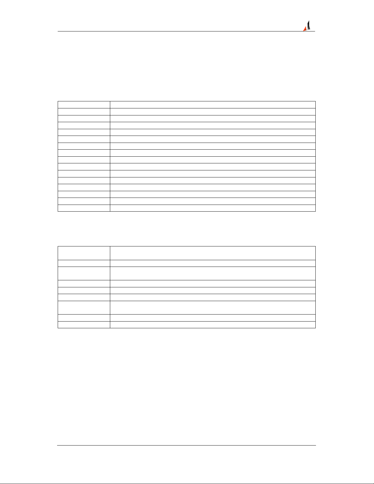
Select an appropriate mounting position for the VP Series 2000 device leaving enough clearance for
both mechanical installation and optimal RF performance. Devices can be mounted by means of a
mounting adaptor directly onto a machine or by using a cemented mounting pad.
A clearance of 100mm or more is recommended for optimal RF performance, but is not mandatory.
Figure 15 - VP Series 2000 - Minimum Installation Clearance
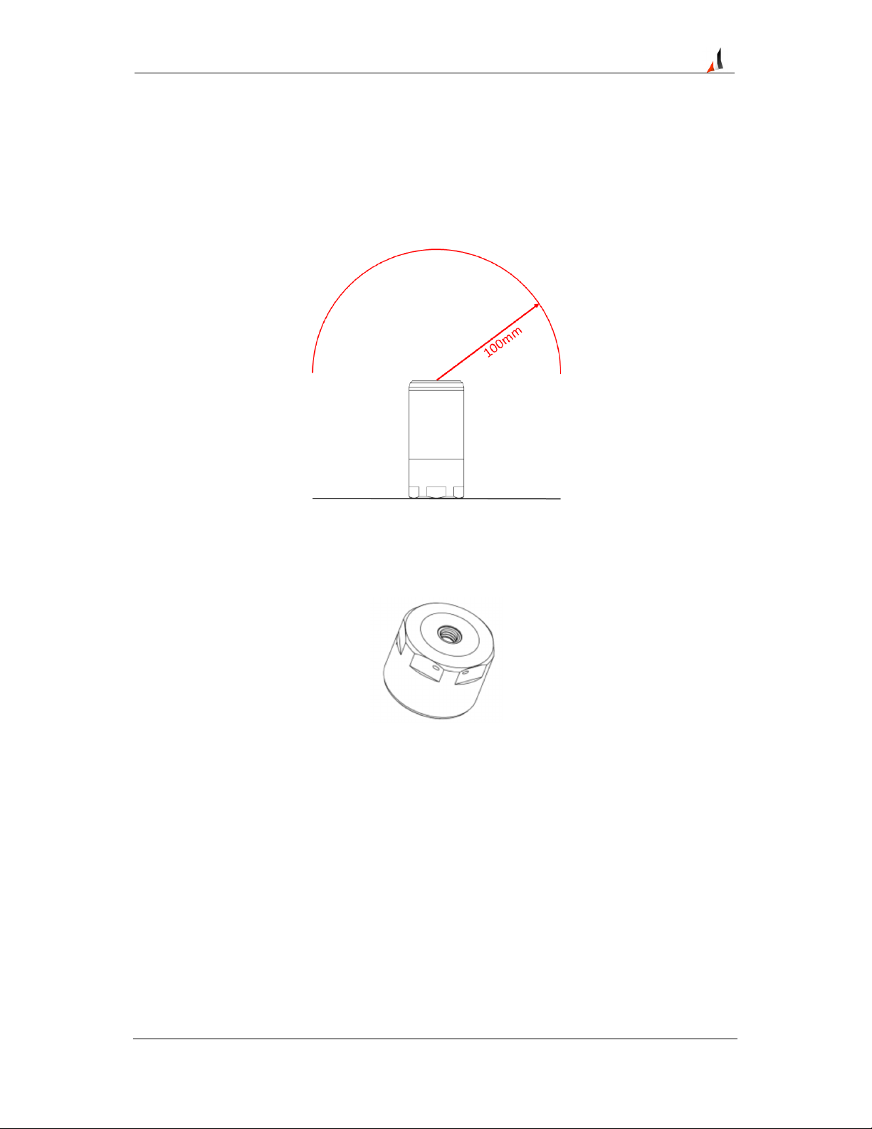
A 1.25mm diameter fall protection hole in the base provides the ability to secure the device using a
stainless steel lanyard to prevent it from falling should the mounting fail.
Figure 16 - VP Series 2000 - Fall Protection Hole
6.1 Mounting Guidelines
To mount the device:
• Prepare a flat, clean surface with a diameter > 40mm on the machine at the mounting point.
• Drill and tap a suitable hole in the centre of the prepared surface.
OR
Cement the mounting pad onto the prepared surface with a suitable bonding agent.
• Hand-tighten the device or use a torque wrench to tighten to 2-3 Nm.
• Optionally attach a lanyard (fixed to a suitable retaining point) through the fall protection hole.
Version 1.01 Proprietary & Confidential - Copyright © 2017 Divigraph (Pty) Ltd. All Rights Reserved Page 21 / 33
Page 22

EVR-VPXDOC-0036-100 VP Series 2000 User Guide
Figure 17 - VP Series 2000 -
Cemented Pad Mount
Figure 18 - VP Series 2000 - Tri-
Axial Alignment Mount
Markings on the device indicate the alignment of the various axes. Should these markings not be
visible, the fall protection hole and a reference notch can be used for alignment purposes.
Note!
Direct stud mounts are generally the most effective mounting method but may not be possible
where machine casings are too thin or may not be allowed due to machine warrantee
conditions.
Cemented pad mounts allow for simpler alignment when mounting tri-axial sensors without
the tri-axial mounting accessory.
6.2 Hardware Installation Best Practices
Consider the following when mounting devices:
• Prior to mounting a device at its final location, provision and verify its radio reception and its
ability to join a network.
• Mount sensors as close as possible to the machine point to be monitored.
• The vertical (z-axis) of VP Series 2000 sensor nodes are the most sensitive - if signal strength
and quality allow for it, mount sensors in the axial or radial direction as applicable.
• Refer to relevant machine documentation to determine whether to use a mounting stud or
cemented pad to mount the device.
• Ensure a suitable flat mounting surface on curved or uneven surfaces by using a spot facing
tool.
• Use a steel brush to remove all paint from a flat mounting surface.
• Use a suitable thread locker to secure mounting studs to the machine.
• Silicone grease between the device and mounting surface improves coupling of high
frequency vibration.
• Use a suitable (preferably low strength) thread locker to secure devices to mounting studs or
pads.
Version 1.01 Proprietary & Confidential - Copyright © 2017 Divigraph (Pty) Ltd. All Rights Reserved Page 22 / 33
Page 23

EVR-VPXDOC-0036-100 VP Series 2000 User Guide
7 Configuration
Configuration of VP Series 2000 devices are network infrastructure vendor dependant. VP Series
2000 device data is generally published using either Modbus or OPC. Publication of this data is
network infrastructure vendor dependant as well. Capability files are provided to enable configuration
of VP Series 2000 devices as well as to enable publication of device data.
Note!
Refer to the applicable vendor documentation to configure devices and setup data
publication.
7.1 Capability Files
Capability files provide an industry standard method of interpretation of device capabilities. The
purpose of a capability file (CF) is to provide a human-readable document which contains the
information required for the host system to interpret the block instantiation capability of a device,
number of possible objects present in a device as well as the default values of the block attributes.
VP Series 2000 device capability files contain information about the capabilities of VP Series 2000
sensors and repeaters.
Note!
Not all host systems require a CF.
Refer to the applicable vendor documentation to determine how to utilise VP Series 2000
capability files if required.
7.2 Data Publishing
Data publishing is a function of the network infrastructure. Depending on the network infrastructure
vendor, data may be published using Modbus or OPC. Modbus is generally an unlicensed method to
publish data while OPC generally requires additional licensing. OPC data mapping and management
is generally simpler than that of Modbus.
Note!
Refer to the applicable vendor documentation to determine whether Modbus or OPC data
publication is available.
7.2.1 Modbus
Most network infrastructure vendors make use of Modbus TCP to publish data. Refer to the vendor
specific documentation for additional information about which Modbus interfaces are available and
how to map VP Series 2000 data to applicable Modbus registers.
7.2.2 OPC
Modbus register data can be published using OPC by means of an OPC server interface on a network
infrastructure host system. This may require a 3rd party OPC server interface. Refer to the OPC server
interface documentation for additional detail on how to map Modbus registers to the OPC server.
Version 1.01 Proprietary & Confidential - Copyright © 2017 Divigraph (Pty) Ltd. All Rights Reserved Page 23 / 33
Page 24

EVR-VPXDOC-0036-100 VP Series 2000 User Guide
Some network infrastructure vendors may have an OPC server interface available to publish data.
Refer to the vendor specific documentation for additional information about which OPC server
interfaces are available and how to map VP Series 2000 data to OPC servers.
Note!
In most cases the OPC server interface requires additional licensing.
Version 1.01 Proprietary & Confidential - Copyright © 2017 Divigraph (Pty) Ltd. All Rights Reserved Page 24 / 33
Page 25

EVR-VPXDOC-0036-100 VP Series 2000 User Guide
8 Operation
During normal operation VP Series 2000 field devices maintain their connection to an ISA100.11a
compliant wireless network and publish vibration and temperature measurements.
In addition devices monitor their own status, perform measurements and publish parameters as
configured.
8.1 Measurements
VP Series 2000 sensors perform various measurements on acquired signals. These include:
• Temperature
o
°C
o
°F
• Vibration
o
g rms
o
g pk
o
m/s2 rms
o
m/s2 pk
• Velocity
o
mm/s rms
o
mm/s pk
o
in/s rms
o
in/s pk
8.1.1 Temperature
VP Series 2000 sensors measure surface contact temperature by means of a temperature sensor in
the sensor base. The temperature can be scaled in degrees Celsius (°C) or degrees Fahrenheit (°F).
Refer to the product data sheet for temperature range and resolution.
8.1.2 Acceleration
VP Series 2000 sensors measure single or tri-axial vibration up to ±20 g (peak) by means of a
piezoelectric ceramic sensing element in the sensor base. The measurement accuracy is ±5% and
transverse sensitivity is typically 7%. Vibration measurements can be scaled as follows:
• g rms
• g pk
• m/s2 rms
• m/s2 pk
Refer to the product data sheet for acceleration range.
8.1.3 Velocity
VP Series 2000 sensors measure single or tri-axial velocity derived from the vibration signal. Velocity
measurements can be scaled as follows:
Version 1.01 Proprietary & Confidential - Copyright © 2017 Divigraph (Pty) Ltd. All Rights Reserved Page 25 / 33
Page 26

EVR-VPXDOC-0036-100 VP Series 2000 User Guide
• mm/s rms
• mm/s pk
• in/s rms
• in/s pk
Refer to the product data sheet for velocity range.
8.2 Parameter Publishing
Measurements are published as parameters to gateways using the wireless network. Parameters are
then published using Modbus or OPC as per the gateway configuration.
Version 1.01 Proprietary & Confidential - Copyright © 2017 Divigraph (Pty) Ltd. All Rights Reserved Page 26 / 33
Page 27

EVR-VPXDOC-0036-100 VP Series 2000 User Guide
9 Maintenance
VP Series 2000 devices have been design to require minimal maintenance. Maintenance tasks
include cleaning the sensor for maintenance purposes, periodic inspection of device components
such as batteries and o-ring seals, cell replacement as well as firmware updates.
9.1 Cleaning
Use a non-abrasive solvent free method to clean the exterior of a VP Series 2000 device prior to
performing any further maintenance to the device. A clean, dry, anti-static cloth should be used to
clean interior components of the device. Switch cleaner may be used to remove deposits from sensor
body contact pads.
Warning!
To prevent electrostatic discharge, only a damp cloth may be used to clean the exterior of VP
Series 2000 devices in hazardous locations.
Opening, disassembly and internal cleaning shall never be performed in hazardous locations.
9.2 Disassembly
Disassemble a VP Series 2000 device as follows:
• Remove the enclosure retainer using oscillating turns to prevent damage to the o-rings. Use a
single counter-clockwise turn followed by a ¼ turn in the opposite direction until the sensor
body o-ring is exposed.
• Remove the e-module by using light, upward pressure on the side opposite the contact pins.
• Remove the cell retaining ring using the cell installation tool.
• Remove the cell.
Warning!
Do not disassemble the device in a hazardous environment.
If the cell is damaged or shows signs of leakage do not continue with the disassembly
process and take appropriate action as per applicable hazardous materials procedures
provided in the cell manufacturer’s material safety datasheet.
Do not short-circuit the cell.
Note!
VP Series 2000 devices should not be disassembled in the field.
Avoid disassembling the device in humid conditions.
Version 1.01 Proprietary & Confidential - Copyright © 2017 Divigraph (Pty) Ltd. All Rights Reserved Page 27 / 33
Page 28

EVR-VPXDOC-0036-100 VP Series 2000 User Guide
9.3 Assembly
Assemble a VP Series 2000 device as follows:
• Insert the cell.
• Insert the cell retaining ring and hand-tighten it to secure the cell using the VP Series 2000
cell installation tool.
• Insert the e-module by angling and aligning the side with the spring loaded contacts first.
Once the spring loaded contacts are aligned, press gently from the opposite end to apply
radial force that compresses the contacts and then apply light downward pressure to the
opposite end.
• Ensure that the sensor body screw thread is clean.
• Ensure that the o-rings are clean, undamaged and in place.
• Ensure that the enclosure retainer screw thread is clean.
• Place the enclosure retainer over the e-module and fasten it until the sensor body o-ring is
covered.
• Use oscillating turns to hand-tighten the retaining ring to prevent damage to the o-rings.
Warning!
Do not assemble the device in a hazardous environment.
Do not short-circuit the cell.
Do not insert a damaged or leaking cell into the device.
Check the cell polarity when inserting it into the device.
Reverse polarisation may cause damage to the device.
Note!
VP Series 2000 devices should not be assembled in the field.
Ensure that components are clean and dry before assembling the device.
Avoid assembling the device in humid conditions.
Correct assembly is essential to maintain the IP67 rating of the device.
9.4 Device Inspection
Internal device inspection is typically only performed during cell replacement and there is no routine
inspection requirement.
The device needs to be removed from the field and cleaned before disassembled. Once
disassembled the components must be inspected for signs of damage before reassembled.
9.4.1 O-Ring Inspection
Two 34x1 o-ring seals are used to prevent dust and moisture penetration into VP Series 2000
devices. Depending on environmental conditions, these seals may have to be replaced periodically
but typically only whenever the cell is replaced.
Refer to the product data sheet for o-ring seal ordering information.
Version 1.01 Proprietary & Confidential - Copyright © 2017 Divigraph (Pty) Ltd. All Rights Reserved Page 28 / 33
Page 29

EVR-VPXDOC-0036-100 VP Series 2000 User Guide
Note!
O-rings should be replaced whenever batteries are replaced.
New o-rings should be coated in silicone grease.
Ensure that o-rings are free of dirt as particles may compromise the IP67 rating of the device.
Warning!
Do not use solvents to clean o-rings - use a clean, dry cloth to remove dirt particles if
required.
Do not use devices with o-rings showing signs of damage.
Using devices with o-rings showing signs of damage may cause further damage or device
failure.
9.4.2 E-Module Inspection
E-modules should be inspected for visible damage to the enclosure, cell terminal spring and contact
pins.
Check the enclosure for signs of degradation or cracks in the material.
Check the cell terminal spring for signs of chemical corrosion or crystallisation.
Contact pins should not be loose but should move freely when pressed against the sensor body
contact pads.
Note!
The e-module contains no user serviceable parts and together with the rest of the device
components, should be returned to the supplier for repair or service if required.
Warning!
Do not use devices with e-modules showing signs of damage in hazardous locations.
Using devices with e-modules showing signs of damage may cause further damage or device
failure.
9.4.3 Cell Inspection
VP Series 2000 device batteries should be inspected for signs of damage or leakage. These include
but are not limited to:
• Deformation of the cell in the form of swelling or elongation.
• Indentations in the cell.
• Lifting of cell terminals.
• Moisture or liquid on the cell.
• Crystallisation or chemical corrosion on the cell terminals.
Warning!
Immediately discontinue the use of a cell that shows any signs of damage or leakage and
refer to relevant hazardous material procedures to dispose of the cell.
Do not use devices with batteries showing signs of damage in hazardous locations.
Version 1.01 Proprietary & Confidential - Copyright © 2017 Divigraph (Pty) Ltd. All Rights Reserved Page 29 / 33
Page 30

EVR-VPXDOC-0036-100 VP Series 2000 User Guide
Using devices with batteries showing signs of damage may cause further damage or device
failure.
Version 1.01 Proprietary & Confidential - Copyright © 2017 Divigraph (Pty) Ltd. All Rights Reserved Page 30 / 33
Page 31

EVR-VPXDOC-0036-100 VP Series 2000 User Guide
9.4.4 Sensor Body Inspection
Sensor bodies should be inspected for visible damage to the enclosure, cell terminal spring and
contact pads.
Check the enclosure for signs of deformation, degradation or cracks in the material.
Check the cell terminal spring for signs of chemical corrosion or crystallisation.
Contact pads should be undamaged and free of any carbon deposits.
Note!
Other than cleaning of the contact pads, the sensor body contains no user serviceable parts
and together with the rest of the device components, should be returned to the supplier for
repair or service if required.
Warning!
Do not use devices with sensor bodies showing signs of damage in hazardous locations.
Using devices with sensor bodies showing signs of damage may cause further damage or
device failure.
9.5 Cell Replacement
Device cells may have to be replaced when they reach a minimum level. Cells are secured inside the
device using a retaining screw-cap that can be loosened and tightened using the VP Series 2000 cell
installation tool. The following steps describe how to replace the VP Series 2000 cell:
• Disassemble the device.
• Insert a cell as per the approved list.
• Replace o-ring seals.
• Assemble the device.
Warning!
Do not replace the cell in a hazardous environment.
Do not short-circuit the cell.
Do not insert a cell type other than as per the approved list.
Do not insert a damaged or leaking cell into the device.
Check the cell polarity when inserting it into the device.
Reverse polarisation may cause damage to the device.
Note!
Batteries should not be installed in the field.
Dispose of expended batteries as per applicable hazardous material disposal procedures.
Transportation regulations often restrict the shipment of lithium-type batteries that have been
fully or partially consumed.
Consult appropriate regulations prior to disposing batteries or seeking service.
Version 1.01 Proprietary & Confidential - Copyright © 2017 Divigraph (Pty) Ltd. All Rights Reserved Page 31 / 33
Page 32

EVR-VPXDOC-0036-100 VP Series 2000 User Guide
9.6 Firmware Updates
VP Series 2000 device firmware can be updated or reverted using the VP Series 2000 software and
Node Docking Station.
Refer to the VP Series 2000 Software User Guide for additional information.
9.7 Device Reset
VP Series 2000 devices can be reset using the VP Series 2000 Software and Node Docking Station.
By resetting a VP Series 2000 device after it has been powered for a long period of time without
joining a network, the device will exit the extended sleep cycle and attempt to join an ISA100.11a
network more frequently.
Refer to the VP Series 2000 Software User Guide for additional information.
Version 1.01 Proprietary & Confidential - Copyright © 2017 Divigraph (Pty) Ltd. All Rights Reserved Page 32 / 33
Page 33

EVR-VPXDOC-0036-100 VP Series 2000 User Guide
10 Security Hardening Guidelines
From an electronic security risk assessment perspective the VP Series 2000 sensors and repeaters
can be categorised the same as CS/DCS/ICSS. For this reason, due diligence should be performed to
ensure all reasonable steps have been taken to properly secure any system using these devices.
Risk Assessment, Network integration and DCS integration are beyond the scope of this document.
This section is presented as a guideline, not a step by step procedure. If assistance is needed, please
contact the applicable supplier.
10.1 System Hardening
The following checks can be done in order to harden a system utilising VP Series 2000 devices:
• Ensure devices have the latest firmware installed.
• Ensure proper management of device docking stations.
• Follow company or industry best practices for strong passwords for the applicable wireless
network infrastructure. Refer to the applicable vendor documentation for wireless network
infrastructure password requirements.
• Install VP Series 2000 software on only task specific computers such as a dedicated laptop
and maintain proper physical security of these computers.
• Avoid installing VP Series 2000 software on unsecured networked computers or computers
that are remotely accessible.
• Patch management is important in maintaining a security posture. Keep firmware and
software current to the latest versions.
10.2 Recommendations for Improved Availability and Reliability
Numerous steps may be taken to maximise cell life and minimise communication interruptions for VP
Series 2000 devices and in so doing improving device availability and reliability.
10.2.1 Cell Life
Considering the following recommendations may achieve improved availability and reliability by
extending cell life:
• Use line powered ISA100.11a compliant routing devices.
• Minimise the number of hops between VP Series 2000 devices and line powered ISA100.11a
compliant routing devices.
• Minimise the number of devices routing through VP Series 2000 repeaters.
• Avoid using VP Series 2000 sensors as routing devices.
• Use the lowest reasonable parameter publishing rate to monitor vibration and temperature.
10.2.2 Network Redundancy
By using redundant ISA100.11a network components, VP Series 2000 device communication
interruption may be minimised to improve availability and reliability. Consider using line powered ISA
100.11a routing devices to provide primary communication routing and using VP Series 2000
repeaters to provide a secondary communication route.
Version 1.01 Proprietary & Confidential - Copyright © 2017 Divigraph (Pty) Ltd. All Rights Reserved Page 33 / 33
 Loading...