

Page 1
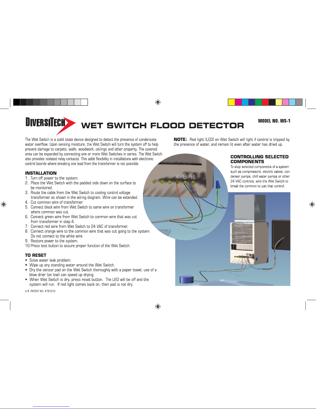
INSTALLATION ol.indd 1 2/1/05 4:19:25 PM
Page 2
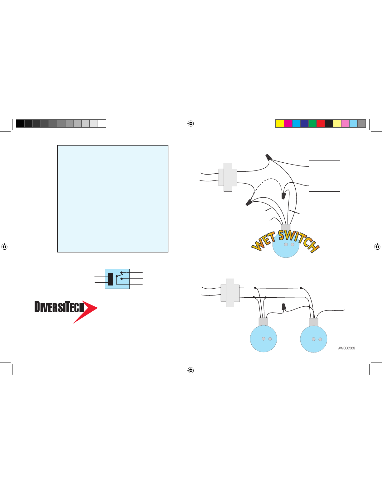
POWER IN
Cooling System Transformer
T yp ic al C on n ec tion
C on n ec tion sh o wing t wo o r m or e w et s witc h e s in s er ie s
The contacts of the Wet Switch’s relay may be wired to use multiple
Wet Switches. The drawing to the right shows the contacts
interrupting the 24 VAC signal when either Wet Switch gets wet.
6650 Sugarloaf Parkway
Duluth, GA USA
800.995.2222
678.542.3700 FAX
www.diversitech.com
SPECIFICATIONS:
INDICATORS:
Green LED – Power
Red LED – Moisture Detected
POWER REQUIREMENTS:
24 VAC 50/60 HZ
1.5 Watts Max (wet) <0.5 Watts (dry)
RELAY:
Isolated Contacts
2 Amps – Normally Closed Contact
2 Amps – Normally Open Contact
LATCHING OPERATION RESET:
Remove power
Dry sensor plates
Re-apply power
Wet Switch Schematic
24 VAC
RED
BLACK
ORANGE
WHITE
GREEN
t-stat
circuit board
or
controls
CUT COMMON WIRE
*
* Check for manufacturers ground.
Cut between transformer and
ground if present.
Orange
Normally Closed when Dry
(Opens when Wet)
Relay Contact Common Green
Red
Red
Black
Blac
k
Normally Open when Dry White
(not connected)
X
24 VAC
To System
Orang
e
Re
d
Red
Blac
k
Blac
k
24 VAC
Red
Gree
n
Gree
n
Orange
Typical Connection
Connection showing two or more Wet Switches in series
INSTALLATION ol.indd 2 2/1/05 4:19:27 PM
 Loading...