

Page 1
i
s
l
e
p
n
r
o
n
d
a
h
C
i
d
e
e
p
S
1
0
0
%
r
e
u
c
e
d
w
i
t
h
y
g
r
e
n
e
n
e
e
l
w
b
a
SpeediChannel
™
System Installation
Page 2

Contents
Introduction
3 DiversiTech Speedichannel™ System
4 Features and Benets
System Installation
6 Step 1
7 Step 2
8 Step 3
9 Step 4
10 Step 5
11 Step 6
Installation Diagrams
12 Indoor and Outdoor installations
14 Flex Joint and Drain Hose diagrams
16 Line Set conguration
17 Air Handler installations
Sizing Chart
21 Dimensions and Capacities
Technical Information
22 General data and safety information
Mini Component Guide
23 Product information and product layout
2
Page 3
DiversiTech SpeediChannel™ System
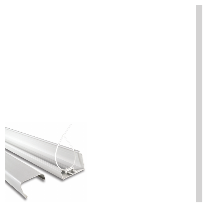
DiversiTech SpeediChannel™ is an innovative channel system used to
cover air conditioning line sets. The two part system has a base and a
cover. The base is fastened to a wall or ceiling, then a clever little plastic
clip (SpeediClip™) snaps into a channel already molded into the base.
SpeediClip™ is the fastest, most convenient way to complete a line set
cover installation. Then, using standard cable ties, the line set, cables, con
trol wires, and/or condensate drain line are fastened in place. The cover
then simply snaps on top of the base.
The SpeediChannel™ system is available in three widths – 3”, 4”, and 6”.
Each piece of SpeediChannel™ is 6-1/2 feet long. A complete line of cou
plings, elbows, and tees are available for the SpeediChannel™ system.
Manufactured from rigid PVC, the SpeediChannel™ system is a natural
color that is a very close match to the typical mini split condensing unit
case. However, the SpeediChannel™ system can be painted as desired
to match any wall color. The PVC used in the SpeediChannel™ system is
resistant to UV light, and is UL rated.
DiversiTech recommends attaching the
base to the wall or ceiling and the line
sets to the system every 15” to allow for
the system to carry the full weight of the
line sets.
The SpeediChannel™ system can also
be used inside.
-
-
I
N
T
R
O
D
U
C
T
I
O
N
3
Page 4

Features and Benets
I
N
SpeediClip™
T
R
O
D
U
Paintable
C
T
Natural color
I
O
N
Large size
• SpeediClip™ simply slides into place on a railing molded
into the inside of the SpeediChannel™ allowing for
single person installation. Competitive products must be
screwed in place
• The SpeediChannel™ can be easily customized to any
wall construction. *See painting specifications below.
• The original natural color blends well with almost any wall
construction aesthetic.
• DiversiTech’s large SpeediChannel™ size is a full 6” chan
nel — unlike competitors’ products which are only 5-1/2”.
which is extremely time consuming.
-
Tight fit corner and flat
bottom channel design
Stainless steel screws
Flat wall escutcheon
Integrated flex joint
Long radius 90º bend
4
• The flat bottom channel sits on surfaces easier and fits into
corners better. It can be silicone sealed against the wall.
• Stainless steel screws will not rust.
• Competitive products have a larger escutcheon that is not
aesthetically pleasing and wastes space.
• Competitive products require a joiner piece to couple
the flex joint to their systems. The DiversiTech flex joint
slides right into the end of the SpeediChannel™ with no
additional joiner piece.
• DiversiTech’s long radius 90º bend allows for a larger
bending radius for the line set, making installation easier.
Page 5

Features and Benets
Single piece wall sleeve
20mm drain line with
double connections
True Y connection
English packaging
• Competitive products are multi-part which is cumbersome.
• Versatile — fits 16, 18, or 20mm drain line.
• Drainline Y is inline. It does not branch.
• Competitive products have Japanese on the boxes, poten
tially leading to product selection errors.
Painting Specications
DiversiTech recommends any 100% acrylic latex or 100% acrylic latex with a urethane additive
when painting SpeediChannel products. The reason for this recommendation is because of the
paint’s flexibility. Lacquers are not recommended with PVC products because lacquers are more
brittle and won’t flex with the channel. Some suggestions: Duration by Sherwin Williams, Manor
Hall paints by PPG and Moorelife by Benjamin Moore. In addition to paint type, only light-tomedium colored paints (Light Reflectance Value of 55% units or greater) should be applied to
SpeediChannel or most any exterior PVC products. Light Reflectance Value (LRV) is a measure
ment that indicates how much light a color reflects. An LRV of 0% is absolute black and an LRV
of 100% is perfectly reflective white. LRV is on the back of most color swatches and in the index
of all major brands’ fandecks. It is not safe to assume the paint is a light color. Some paints that
appear light beige can have an LRV in the 20s or 30s.
I
N
T
R
O
D
U
C
-
T
I
O
N
-
5
Page 6
Step 1
S
Y
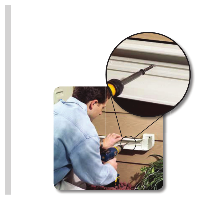
Attach the SpeediChannel™ base to the wall about every 15 inches
S
with screws suitable for the wall construction (siding, stucco, brick, etc.).
T
Screw through the center of the molded rail. Slide the
E
connecting piece (elbow, union, tee, etc.) under the
M
SpeediChannel™ before attaching the end of the
channel to the wall. When cutting lengths of
I
SpeediChannel™, allow 1/8” gap between
the end of the SpeediChannel™ and the
N
stop inside the fitting to allow for
S
thermal expansion.
T
A
L
L
A
T
I
O
N
6
Page 7

Step 2
Slide one SpeediClip™ with cable tie about every 20 inches along the inside sliding rail.
S
Y
S
T
E
M
I
N
S
T
A
L
L
A
T
I
O
N
7
Page 8
Step 3
S
Y
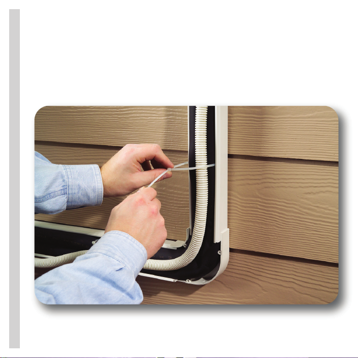
Install the line set, drain line, and wires inside the SpeediChannel™. Test the equipment
S
installation prior to tightening the cable ties. Tighten the cable ties snug, but not so tight they
T
damage the tubing insulation or kink the drain line. Trim excess length from the cable tie.
E
M
I
N
S
T
A
L
L
A
T
I
O
N
8
Page 9
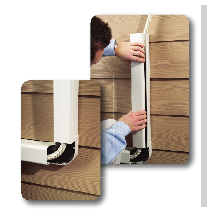
Step 4
Attach the SpeediChannel™ to the base.
S
Y
S
T
E
M
I
N
S
T
A
L
L
A
T
I
O
N
9
Page 10
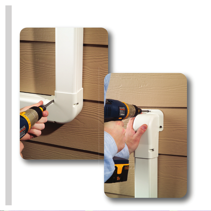
Step 5
S
Y
Attach the fitting covers with the screws provided.
S
T
E
M
I
N
S
T
A
L
L
A
T
I
O
N
10
Page 11
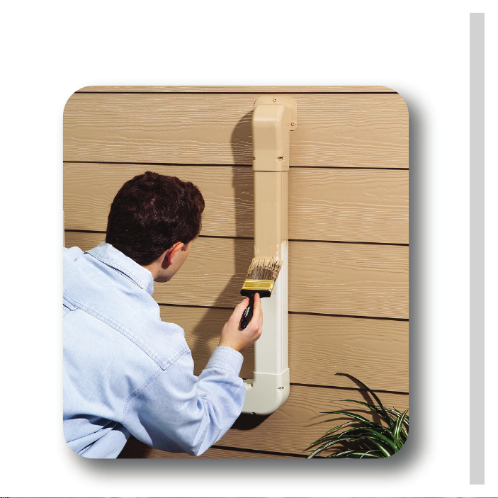
Step 6
When complete, paint the SpeediChannel™
to match surface of installation (if desired).
S
Y
S
T
E
M
I
N
S
T
A
L
L
A
T
I
O
N
11
Page 12
I
N
S
T
A
L
L
A
T
I
O
N
D
I
A
G
R
A
M
S
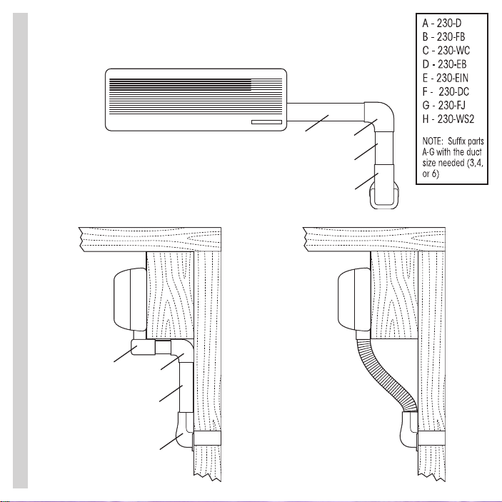
Typical Detail of Indoor Installation
A
B
A
C
E
D
A
C
12
Page 13
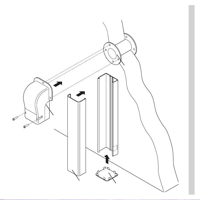
Typical Detail of Outdoor Installation
C
I
N
S
T
A
L
L
A
T
H
I
O
N
D
I
A
G
R
A
M
S
A
F
13
Page 14
I
N
S
T
A
L
L
A
T
I
O
N
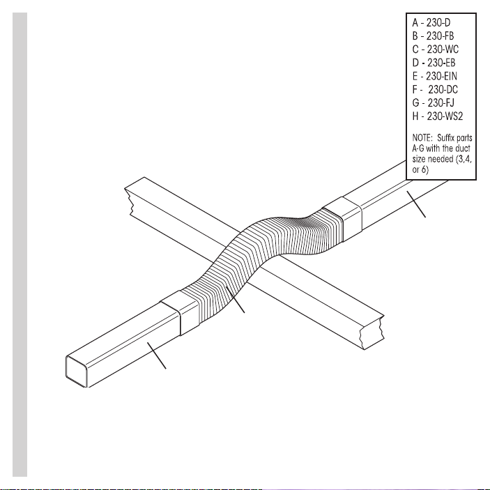
Typical Detail of Flex Joint Application
D
I
A
G
R
A
M
S
G
A
A
14
Page 15
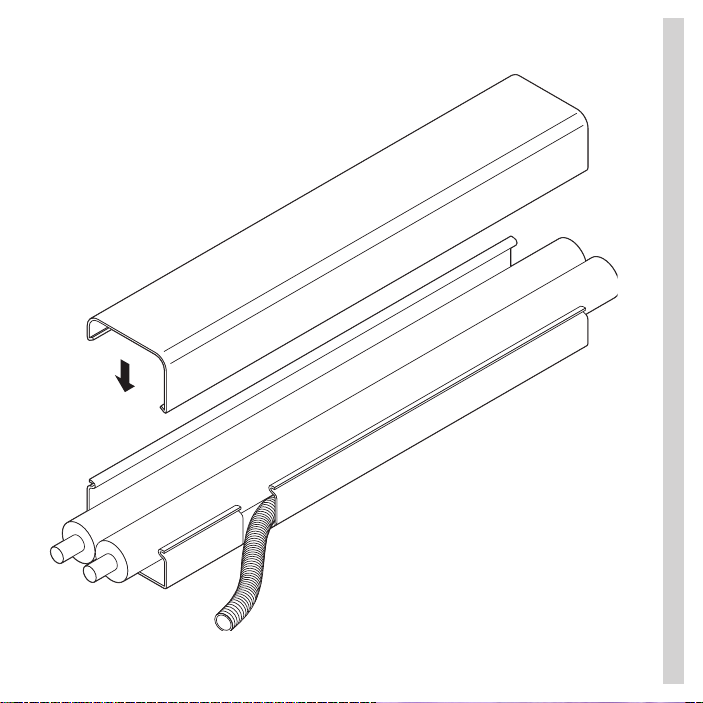
Typical Detail of Cut-out for Drain Hose
Notch bottom half as
shown here.
I
N
S
T
A
L
L
A
T
I
O
N
D
I
A
G
R
A
M
S
15
Page 16
I
N
S
T
A
L
L
A
T
I
O
N
D
I
A
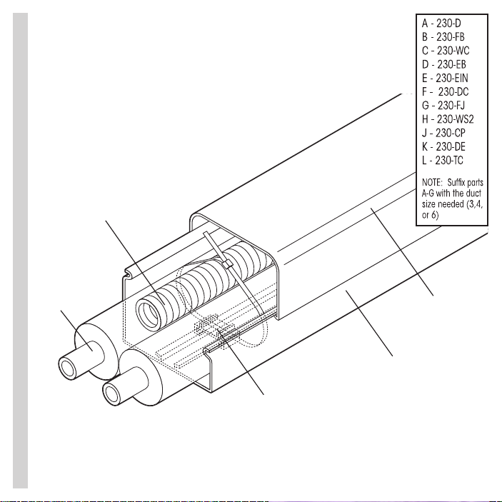
Insulated
G
Refrigerant
R
A
M
S
Drain Hose
Line
Typical Line Set, Cable, and Drain
Hose Configuration
SpeediChannel™
Top
SpeediChannel™
Bottom
SpeediClip™
16
Page 17
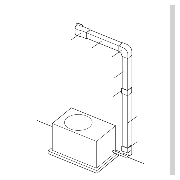
Basic Application - 1 Air Handler
C
A
B
I
N
S
T
A
L
L
A
T
I
O
N
A
J
A
D
I
A
G
R
A
M
S
K
17
Page 18
I
N
S
T
A
L
L
A
T
I
O
N
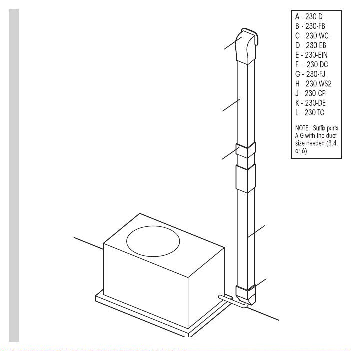
Vertical Dual Air Handler
System Application
C
A
D
I
A
G
R
A
M
S
J
A
K
18
Page 19
C
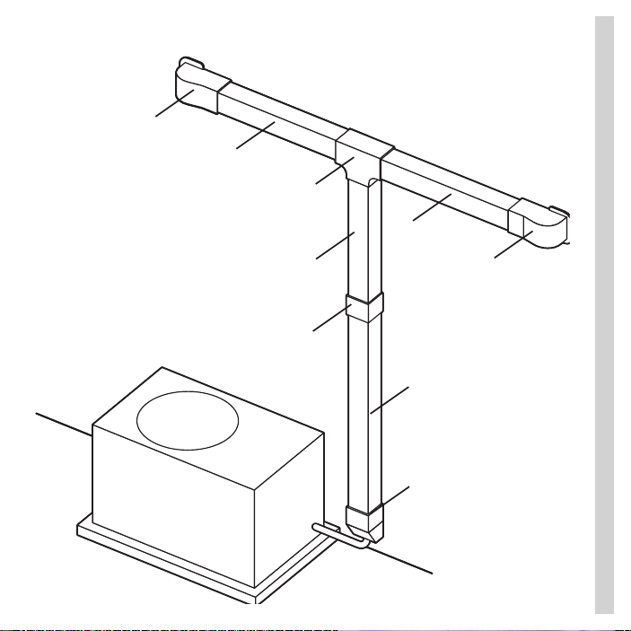
Horizontal Dual Air Handler
System Application
A
L
A
A
J
A
K
I
N
S
T
A
L
L
A
T
I
O
N
C
D
I
A
G
R
A
M
S
19
Page 20
I
N
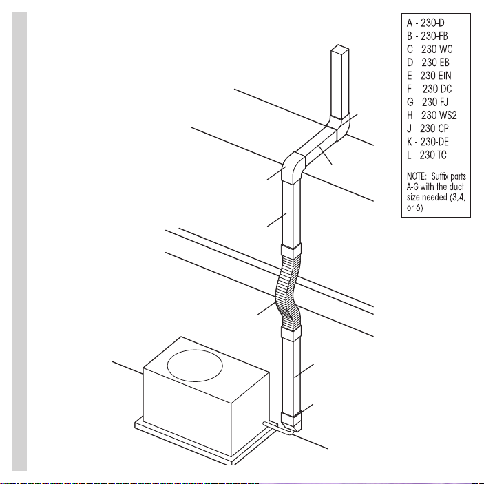
Building with Dierent Wall
Thickness Application
S
T
A
L
L
D
A
T
I
O
N
E
A
D
I
A
A
G
R
A
M
S
20
G
A
K
Page 21
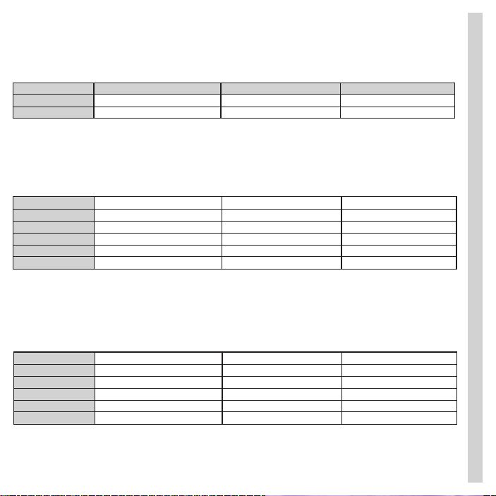
Sizing Chart and Selection Information
Maximum Line Set, Drain Pipe, and Cable Capacity using 3/8” Insulation
Model 2 30-D3 2 30-D4 2 30-D6
Dimensions 3” x 2-1/2” 4” x 2-3/4” 6” x 3”
Length 78” 78” 78”
Mini Split Systems – Liquid and Suction Line with 3/8” Insulation
Liquid Line 3/8” 2 x 1/4” 1 x 1/4” + 2 x 3/8”
Suction Line 5/8” 2 x 3/8” 1 x 1/2” + 2 x 5/8”
Drain Hose 3/4” OD 2 x 3/4” OD 3 x 3/4” OD
Power Cable 1 x UF 14-3 2 x 1/2” SealTite 3 x 1/2” SealTite
Control Cable 1 Pair 18 AWG 2 Pairs 18 AWG 3 Pairs 18 AWG
Nominal Tonnage 1–3 Tons 1x3 Ton or 2x1 Ton 1x3 Ton or 2x2 Ton
Conventional Split Systems – Liquid Line Plain, Suction Line with 3/8” Insulation
Liquid Line 3/8” 3/8” 3/8”
Suction Line 3/4” or 7/8” 1-1/8” 1-1/8”
Drain Hose 3/4” PVC 3/4” PVC 3/4” PVC
Power Cable 1 x UF 14-2 1 x 1/2” SealTite 1 x 1/2” SealTite
Control Cable 1 Pair 18 AWG 1 Pair 18 AWG 1 Pair 18 AWG
Nominal Tonnage Up to 3.5 Tons 4–5 Tons 7.5 Tons and up
S
I
Z
I
N
G
C
H
A
R
T
21
Page 22
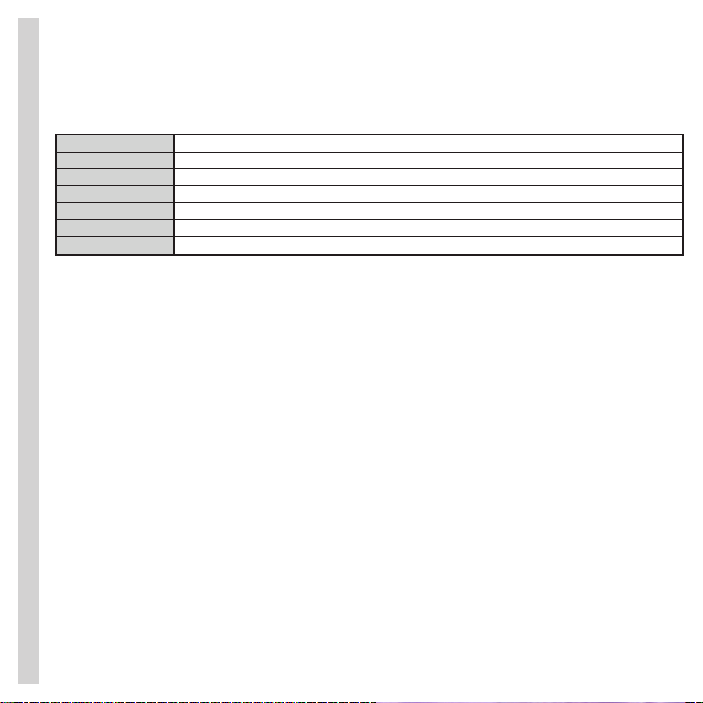
Technical Data
T
E
C
H
N
I
Color Natural
Size
C
Material Weather Resistant PVC, UV Stabilized and Fire Resistant
A
Fire Rating Meets UL 94V.-0
L
Temperature Range - 4˚F TO 140˚F
Weather Resistance Tested to over 2,000 hours
Fixing Screws Stainless Steel
S
230-D3: 3” x 2-1/2” OD 230-D4: 4” x 2-3/4” OD 230-D6: 6” x 3-1/8” OD Standard Length: 78”
P
E
C
I
F
I
C
A
T
I
O
N
S
22
Page 23
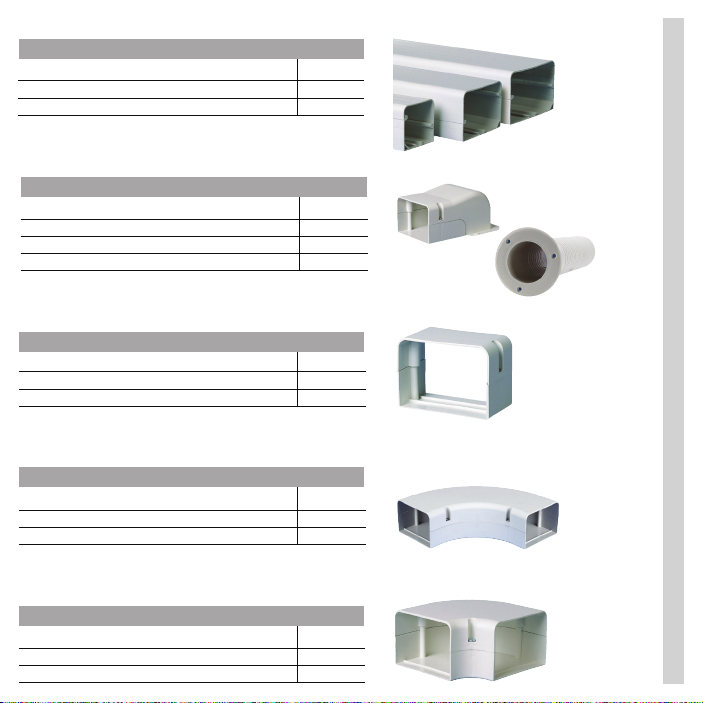
SpeediChannel™
CATALOG NO. DESCRIPTION QTY. NEEDED
2 30-D3 3” SpeediChannel™ – 6-1/2’ long
2 30-D4 4” SpeediChannel™ – 6-1/2’ long
2 30-D6 6” SpeediChannel™ – 6-1/2’ long
Wall Penetration
CATALOG NO. DESCRIPTION QTY. NEEDED
2 30-WC3 3” Wall Penetration
2 30-WC4 4” Wall Penetration
2 30-WC6 6” Wall Penetration
2 30-WS2 2-1/2” Wall Sleeve
Union Coupling
CATALOG NO. DESCRIPTION QTY. NEEDED
2 30-CP3 3” Union Coupling
2 30-CP4 4” Union Coupling
2 30-CP6 6” Union Coupling
90º Long Radius Flat Bend
CATALOG NO. DESCRIPTION QTY. NEEDED
2 30-LFB3 3” 90 deg Long Radius Flat Bend
2 30-LFB4 4” 90 deg Long Radius Flat Bend
2 30-LFB6 6” 90 deg Long Radius Flat Bend
90º Flat Bend
CATALOG NO. DESCRIPTION QTY. NEEDED
2 30-FB3 3” 90 deg Flat Bend
2 30-FB4 4” 90 deg Flat Bend
2 30-FB6 6” 90 deg Flat Bend
I
N
I
C
O
M
M
P
O
N
E
N
T
G
U
I
D
E
23
Page 24
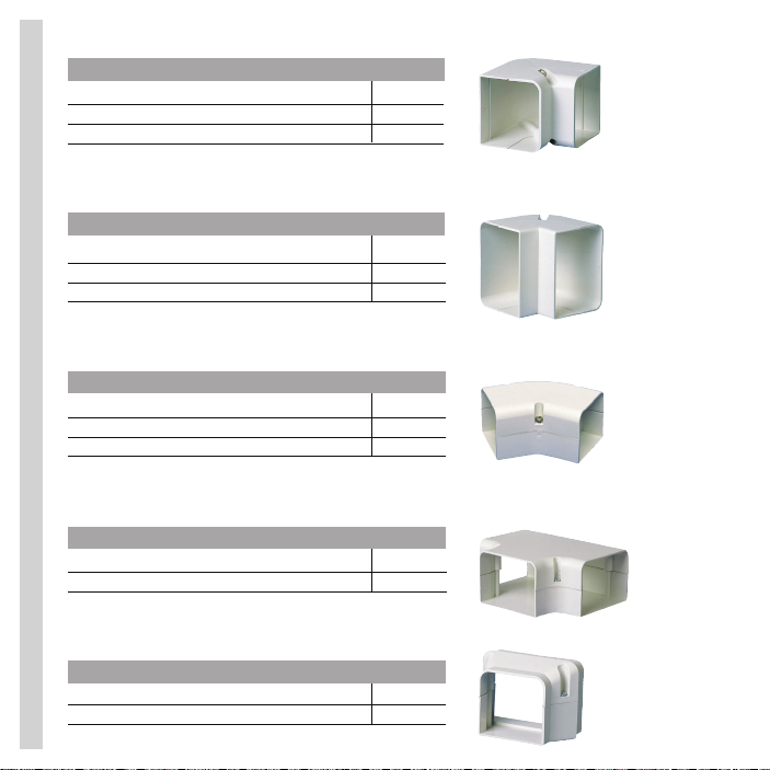
M
90º Inside Elbow
I
CATALOG NO. DESCRIPTION QTY. NEEDED
N
2 30-EB3 3” 90 degree Inside Elbow
I
2 30-EB4 4” 90 degree Inside Elbow
2 30-EB6 6” 90 degree Inside Elbow
C
O
90º Outside Elbow
M
CATALOG NO. DESCRIPTION QTY. NEEDED
P
O
2 30-EIN3 3” 90 degree Outside Elbow
2 30-EIN4 4” 90 degree Outside Elbow
N
2 30-EIN6 6” 90 degree Outside Elbow
E
N
T
45º Flat Bend
CATALOG NO. DESCRIPTION QTY. NEE DED
G
2 30-FB453 3” 45 degree Flat Bend
U
2 30-FB454 4” 45 degree Flat Bend
I
2 30-FB456 6” 45 degree Flat Bend
D
E
T-Joint
CATALOG NO. DESCRIPTION QTY. NEE DED
2 30-TJ4 4” T-Joint
2 30-TJ6 6” T-Joint
Reducer Coupling
CATALOG NO. DESCRIPTION QTY. NEE DED
2 30-TC34 3” x 4” Reducer Coupling
2 30-TC46 4” x 6” Reducer Coupling
24
Page 25
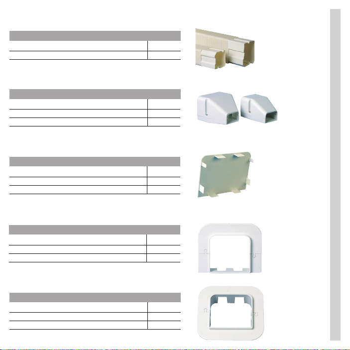
Flex Joint
CATALOG NO. DESCRIPTION QTY. NEEDED
230-FJ3 3” Flex Joint
230-FJ4 4” Flex Joint
Duct End
CATALOG NO. DESCRIPTION QTY. NEEDED
230-DE3 3” Duct End
230-DE4 4 ” Duct End
230-DE6 6” Duct End
Cap
CATALOG NO. DESCRIPTION QTY. NEEDED
230-DC3 3” C ap
230-DC4 4” Cap
230-DC6 6” C ap
Flat Wall Escutcheon
CATALOG NO. DESCRIPTION QTY. NEEDED
230-FR3 3” Flat Wall Escutcheon
230-FR4 4 ” Flat Wall Escutcheon
230-FR6 6” Flat Wall Escutcheon
Wall Escutcheon
CATALOG NO. DESCRIPTION QTY. NEEDED
230-WR3 3” Wall Escutcheon
230-WR4 4 ” Wall Escutcheon
230-WR6 6” Wall Escutcheon
M
I
N
I
C
O
M
P
O
N
E
N
T
G
U
I
D
E
25
Page 26
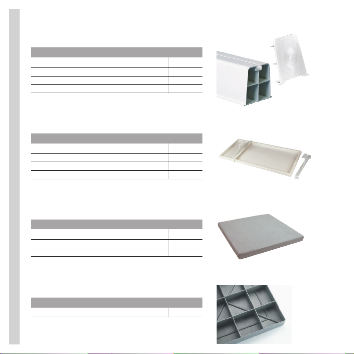
M
I
N
Mounting Blocks
I
CATALOG NO. DESCRIPTION QTY. NEEDED
230-MB14W 14” MountBlock (White) pack of 2
230-MB17W 17” MountBlock (White) pack of 2
C
230-MB36W 36” MountBlock (White) pack of 2
O
230-MBCW MountBlock End Cap (White) pack of 4
M
P
O
Condensate Drain Pans
N
E
CATALOG NO. DESCRIPTION QTY. NEEDED
230-DPPL Poly Cond Drain Pan (Large)
N
230-DPML Metal Cond Drain Pan (Large)
T
230-DPPM P oly Cond Drain Pan (Medium)
230-DPMM Metal Cond Drain Pan (Medium)
G
U
I
UltraLite® Equipment Pads
D
CATALOG NO. DESCRIPTION QTY. NEEDED
E
UC1636-2 16” x 36” x 2” UltraLite® Equipment Pad
UC1636-3
UC2448-2 24” x 48” x 2” UltraLite® Equipment Pad
16” x 36” x 3” UltraLite® Equipment Pad
E Lite® Equipment Pads
CATALOG NO. DESCRIPTION QTY. NEEDED
EL1838-3 1 8” x 38” x 3” E Lite® Equipment Pad
26
Page 27
M
I
N
I
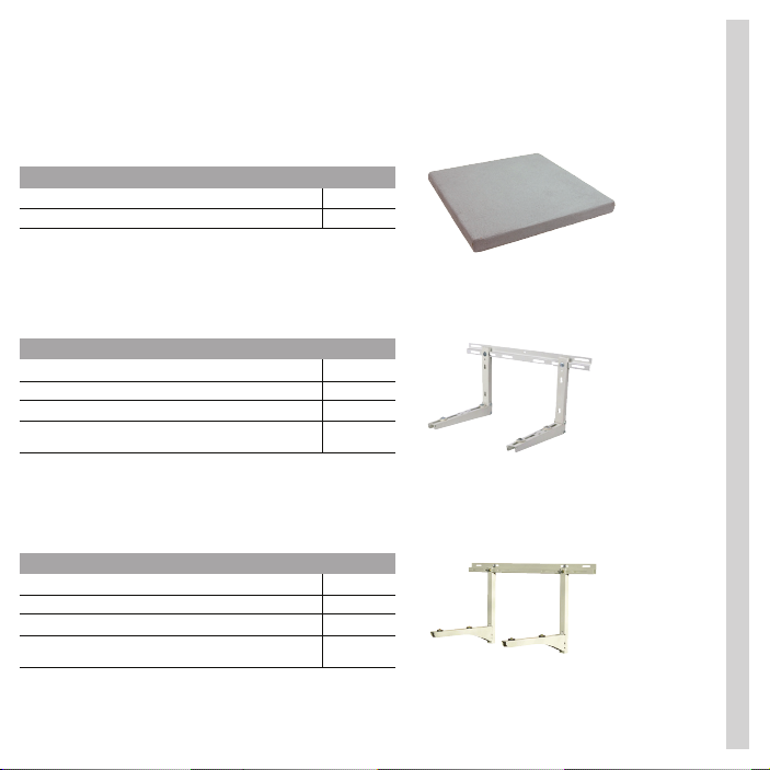
CladLite® Equipment Pads
CATALOG NO. DESCRIPTION QTY. NEEDED
1636-2
1636-3
16” x 36” x 2” CladLite® Equipment Pad
16” x 36” x 3” CladLite® Equipment Pad
Type 2 Wall Brackets
CATALOG NO. DESCRIPTION QTY. NEEDED
230-B2L Type 2 Wall Brackets (Large)
230-B2M Type 2 Wall Brackets (Medium)
Arm Length 21” (Large), 18” (Medium)
Load Rating 220 lbs. (Large), 165 lbs. (Medium)
per Arm
Type 3 Wall Brackets
CATALOG NO. DESCRIPTION QTY. NEEDED
230-B3L Type 3 Wall Brackets (Large)
230-B3M Type 3 Wall Brackets (Medium)
Arm Length 21” (Large), 19” (Medium)
Load Rating 150 lbs. (Large), 100 lbs. (Medium)
per Arm
C
O
M
P
O
N
E
N
T
G
U
I
D
E
27
Page 28
6650 Sugarloaf Parkway
Duluth, GA 30097
678.542.3600
800.995.2222
678.542.3700 Fax
Send edits / corrections / comments on this
catalog to [email protected]
About DiversiTech
DiversiTech Corporation is North America’s
largest manufacturer of equipment pads and a
leading manufacturer and supplier of components and related products for the heating,
ventilating, air conditioning, and refrigeration
(HVACR) industry.
Headquartered in the Atlanta, GA metropolitan
area, DiversiTech manufactures a suite of
products which includes a wide range of
mechanical, electrical, chemical, and structural
parts for HVACR and electrical systems, and
swimming pool installations. The company
maintains manufacturing and distribution
facilities in key U.S. locations, Europe, and in the
Far East. DiversiTech has enjoyed a continued
history of successful growth and has acquired
industry-recognized names including Devco®
Enterprises, Wagner® Manufacturing, The Black
Pad®, Hef-T-Pad™, and Specialty Chemical.
DOC32066
©2017 DiversiTech Corporation
Form no. LIT-INSTR-MSPLIT
Download an electronic copy of these
instructions at www.diversitech.com
 Loading...