

Page 1
Lighting Systems
Owners Manual
Read this manual, in its entirety, before using your light. Failure
to follow the instructions it gives, or to heed the warnings it
provides, can lead to serious personal injury or death.
117 West Washington Street • Lake City, FL 32055 • USA
Phone (386) 752-1087 • Fax (386) 755-0613
www.diverite.com
Page 2

Light System Owner’s Manual Page 2
Dive Rite Lighting System Limited Warranty
➤ Dive Rite will — at its sole discretion — repair or replace dive light components proved to
be damaged by faulty manufacture or material, at no cost, for a period of up to one year (365
days) from the date of purchase.
➤ Canister bodies and the metal portions of light heads are warranted for the life of the product.
➤ Batteries are warranted against defects in manufacture or material for 90 days from date of
purchase. This warranty does not cover loss of battery “burn time”—a condition that results
almost exclusively from mis-use or abuse. Users must read and study the rated “burn time”
information appearing in this manual. Failure to do so can easily result in expensive damage not
covered under warranty.
➤ Attempting the charge damaged batteries can further result in damage to chargers. This is
not covered under warranty — nor is damage to chargers caused by nonstandard alternating
current voltages or cycle rates. Chargers returned under warranty must be accompanied by the
battery(s) they were being used to charge. If the battery(s) are determined to be the cause of
charger damage, no warranty coverage will be provided.
➤ The warranty also specifi cally excludes bulbs, lenses, fuses, O-rings or other conditions resulting
from misuse, negligence, failure to properly lubricate O-rings, alteration, accident or unauthorized repair.
➤ This warranty applies only to the original retail purchaser. It does not cover commercial or
rental use, nor does it extend to units purchased from other than an authorized Dive Rite dealer
or Tekreational Dive Center.
➤ To make a claim under this warranty, the owner must have either completed and returned
the warranty registration card at the time of purchase, or registered his/her warranty using
Dive Rite’s website (www.diverite.com). He or she must then return the damaged items to Dive
Rite, along with a copy of the original purchase invoice or receipt. No warranty service will be
performed for other than registered owners.
➤ This warranty becomes void if dive light components are damaged by anything other than
normal recreational diving use, of if they have been serviced or repaired by other than
authorized Dive Rite dealers.
➤ Repairs made under this warranty will not extend the warranty period.
➤ All further claims, especially for damage after diving accidents, are excluded from coverage
under this warranty.
➤ Lamartek, Inc., dba Dive Rite, has no obligation to honor any extension of this warranty.
All Dive Rite light systems are pressure tested at the factory prior to delivery. When light systems
are returned to Dive Rite for warranty service, the fi rst thing we do is assemble the light precisely
as outlined in this manual, including proper lubrication and installation of O-rings. We then
pressure test the light, just as we did when new. If the light passes this second pressure test, we
have to assume that any reported fl ooding must have resulted from failure to properly assemble
and/or maintain the light as outlined in this manual — in which case no warranty coverage is
provided.
© 1997-2001, Lamartek, Inc., dba Dive Rite • All Rights Reserved Version Date: 01.06.11
Page 3

Light System Owner’s Manual Page 3
Table of Contents
Light Systems Overview............................................................4
High-Intensity Discharge (HID) Light Heads..........................................................5
Quartz-Halogen Light Heads ...................................................................................7
Battery Canisters ......................................................................................................9
Batteries .................................................................................................................15
Switch Mechanisms................................................................................................17
Light System Packages............................................................................................18
Light System Accessories ........................................................................................19
Using Your Light System..........................................................21
Transporting Your Light System .............................................................................22
Charging Your Light System...................................................................................23
Assembling Your Light System ...............................................................................25
Testing Light Operation.........................................................................................31
Mounting Your Light System .................................................................................32
Maintaining Your Light System................................................36
Post-Dive Maintenance and Care ...........................................................................37
Changing Actuators................................................................................................37
Changing or Replacing Bulbs.................................................................................38
Making Batteries Last.............................................................................................44
Dealing with Flooding or Other Damage...............................................................46
Page 4
Light System Owner’s Manual Page 4
Before You Start…
This information has been developed for your safety. Please read and understand this
manual completely before using your Dive Rite light system.
This manual contains important safety and maintenance infor-
mation. Read this manual thoroughly and become familiar with
all of your scuba equipment before diving.
Important information regarding the use or maintenance of your dive light is
designated, throughout this manual, by the Important symbol appearing above. This
manual also uses several signal words to designate hazards with various levels of
seriousness. These are:
Indicates a potentially hazardous situation which, if not
avoided, could result in damage to or loss of equipment, serious
personal injury or death.
Indicates a potentially hazardous situation which, if not
avoided, may result in minor or moderate injury, or equipment
damage. It may also be used to alert against unsafe practices.
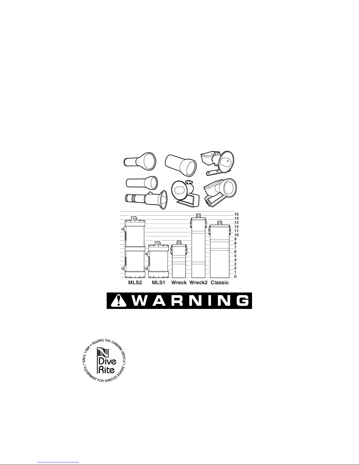
Light Systems Overview
Dive Rite light system components enable users to choose from:
➤ Three different High-Intensity Discharge (HID) light heads and four different
quartz-halogen light heads.
➤ Five different battery canister confi gurations.
➤ Two different switching mechanisms.
➤ A variety of accessories and bulbs in several different wattages.
Page 5

Light System Owner’s Manual Page 5
High-Intensity Discharge (HID) Light Heads
Dive Rite’s HID light heads enable divers to carry with them a compact, selfcontained underwater light system that is capable of providing a level of illumination
previously available only from lights using surface-supplied power. Among their key
features:
➤ To the eye, a 10-watt HID bulb’s outputs is comparable to that of a 50-watt
quartz-halogen bulb. How can this be? Due, in part, to a substantial difference in
color temperature, the perceived output and penetrating power of an HID light is
noticeably greater. Also, just as a fl uorescent bulb consumes only a fraction of the
wattage that a comparable incandescent bulb does, the HID bulb consumes but a
tiny fraction of the power a comparable quartz-halogen bulb demands.
➤ Because it requires just a fraction of the wattage a comparable quartz-halogen bulb
would, HID light system burn times are substantially longer. With a new, singlesection MLS battery pack, the recommended maximum burn time for a Compact
HID light is 300 minutes — roughly four times greater than it would be for a
50-watt quartz-halogen bulb.
➤ An HID’s light output has a color temperature of 6,000–6,500 degrees Kelvin.
This is substantially higher (and whiter) than the typical quartz-halogen light’s
color temperature of 3,000 degrees Kelvin. In fact, it is essentially the same color
temperature as the sun. As a result, an HID light is a much better choice for
underwater video — and nearly any other underwater activity.
➤ Quartz halogen bulbs normally yellow in color and/or decrease in brightness as
battery voltage drops. In contrast, an HID Light’s system circuitry helps keep
light output constant. In fact, an HID light is capable of drawing battery packs
down past recommended voltage levels, without any noticeable decrease in output.
For this reason, it is important users keep light use well within recommended
“burn” times.
Available Models Dive Rite HID light heads are available in three different models.
➤ 10-Watt Compact HID The compact HIS light head looks like a slightly thicker
(but signifi cantly shorter) version of our standard MR11, quartz-halogen light
head. The head contains not only the bulb, but the ultra-small ballast assembly
as well (there is no external “ballast box,” as is necessary on the 17- and 18-watt
models). So small and so light is this head that we do not even use a standard
or “Ergo” hand mount with it. Instead, a simple elastic band that slides over two
fi ngers enables the head to rest comfortably on the back of your hand.
➤ 18-Watt H1 HID This version uses the same test-tube style lens as the regular H1,
and accepts special versions of the compact H1 refl ector or the larger Lumedyne
video refl ector (item number 6270HID). The standard hand mount for the H1-
Page 6
Light System Owner’s Manual Page 6
style HID light head is Dive Rite’s 6126E “Ergo” mount, which attaches directly to
the refl ector collar. (A standard hand mount can also be attached to the H1 HID
light head’s ballast box, either by special order, or as an after-market item.)
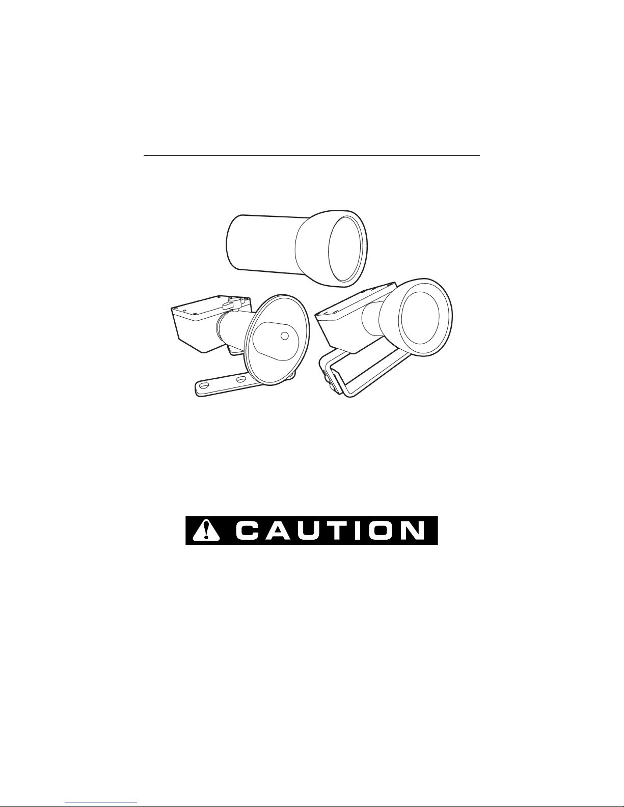
Figure 1 Compact, H1- and MR11-style HID light heads.
➤ 17-Watt MR11 HID The front half of this light head is almost indistinguishable
from its quartz-halogen cousin. The hand mount for the MR11 HID light head is
Dive Rite’s 6126 standard hand mount; this attaches directly to the ballast box.
What Make HID Bulbs Different Among the things that distinguish HID bulbs
from incandescent models is that they have no fi lament. Like a fl uorescent bulb, the
HID creates illumination by creating an arc between poles. The result is an extremely
bright and powerful beam.
The HID is designed for underwater use only. Water not only
provides the necessary cooling medium, it acts as a natural
ultraviolet (UV) fi lter. Still, users should avoid looking directly
at the bulb, even though it is under water.
Expected bulb life is 1,100 hours — provided you don’t drop it. The HID bulb is
somewhat more impact resistant than most quartz-halogen bulbs, in that there is
no fi lament to break. It is not bulletproof, however. You should not, for example,
repeatedly turn the light on and off.
Page 7

Light System Owner’s Manual Page 7
Once activated, you should give the bulb at least four minutes
to warm up to operating temperature before turning it off.
Failure to do so will damage the bulb and is not covered under
warranty. Tr eat the bulb with care, always keeping in mind that
it is among the most expensive components in the system and
fi nancially painful to replace.
Ballast Incorporated into each HID light head is a self-contained ballast assembly.
The HID ballast fulfi lls two important functions. At start-up, the it converts the
battery pack’s normal 12-volt output to the substantially higher voltage (6,000 volts!)
needed to create an arc in the HID bulb.
Following start-up, the ballast continues to function as a converter, providing
the somewhat higher voltage necessary to maintain the arc. In so doing, it maximizes
battery output, resulting in the light’s unusually long burn times.
The HID ballast box contains no user-serviceable parts. Opening
the ballast box voids all warranty coverage.
Quartz-Halogen Light Heads
Although quartz-halogen lights are not as energy effi cient as HID lights (and do
not offer the HID lights’ exceptional burn times), they do have the advantage of
costing substantially less. This makes them a good choice when initial purchase price
is a consideration.
Four different quartz-halogen light heads are available for Dive Rite light
systems. These light heads all have a military specifi cation (mil-spec) coating that
enables them to stand up to the rigors of saltwater diving. Here is a description
of each light head.
MR16 The MR16 is among the most versatile of Dive Rite light heads. MR16
bulbs provide a combination of moderately wide fl ood pattern coverage, with slightly
more intense spot coverage in the center of the beam. Wide-angle coverage bulbs are
available that provide a softer, more even coverage required for video lighting.
The aluminum casing that houses the MR16 bulb is particularly rugged. It
resists damage from crushing (although the MR16 bulb fi lament can be broken by
the impact that results from accidentally dropping the head on a hard surface). This
casing makes the MR16 head the best choice for operating in environments that are
especially hard on equipment.
Page 8
Light System Owner’s Manual Page 8
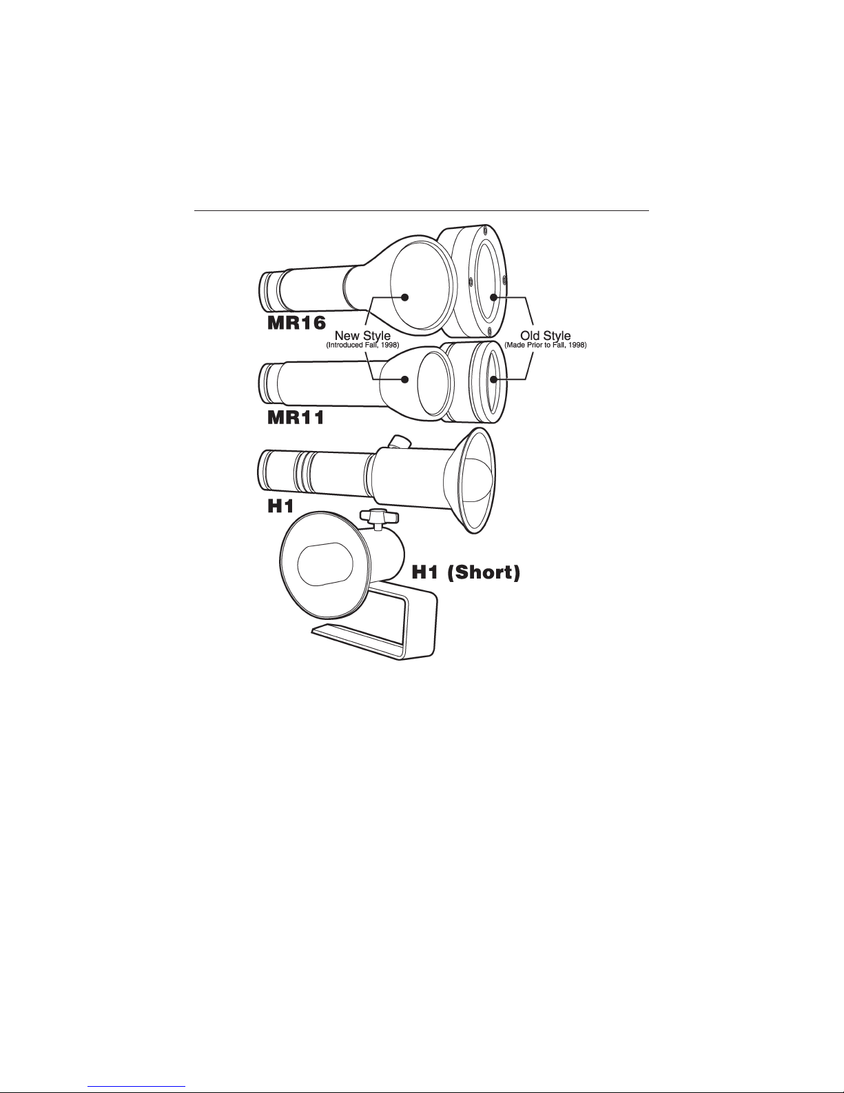
Figure 2 Quartz-Halogen light head options.
MR11 The MR11 is a compact version of the MR16. Although its beam pattern
is not as wide or as even as that of the MR16, the MR11 has the advantage of
being much more streamlined. This makes the MR11 an excellent choice for helmetmounted light heads, or light heads that will be used in high-fl ow situations.
H1 The H1 light head is designed primarily for cave diving. A compact, adjustable,
2.75-inch/70 mm refl ector allows the beam pattern to be focused from a moderately
wide fl ood to a highly penetrating pinpoint spot light that is highly suitable for
exploration. Also available is a special video refl ector (item number 6270) that
provides the widest and softest beam possible for underwater cinematography and
video.
H1 “Short” The H1 “Short” light head is an ultra-light, ultra-compact version of the
regular H1 light head, that is less than half as long as its actuator-style brother. It
Page 9
Light System Owner’s Manual Page 9
comes with its own built-in “ergo” hand mount and is a favorite among some of the
world’s most experienced cave divers. The H1 “Shorty” is available in a toggle-switch
confi guration only.
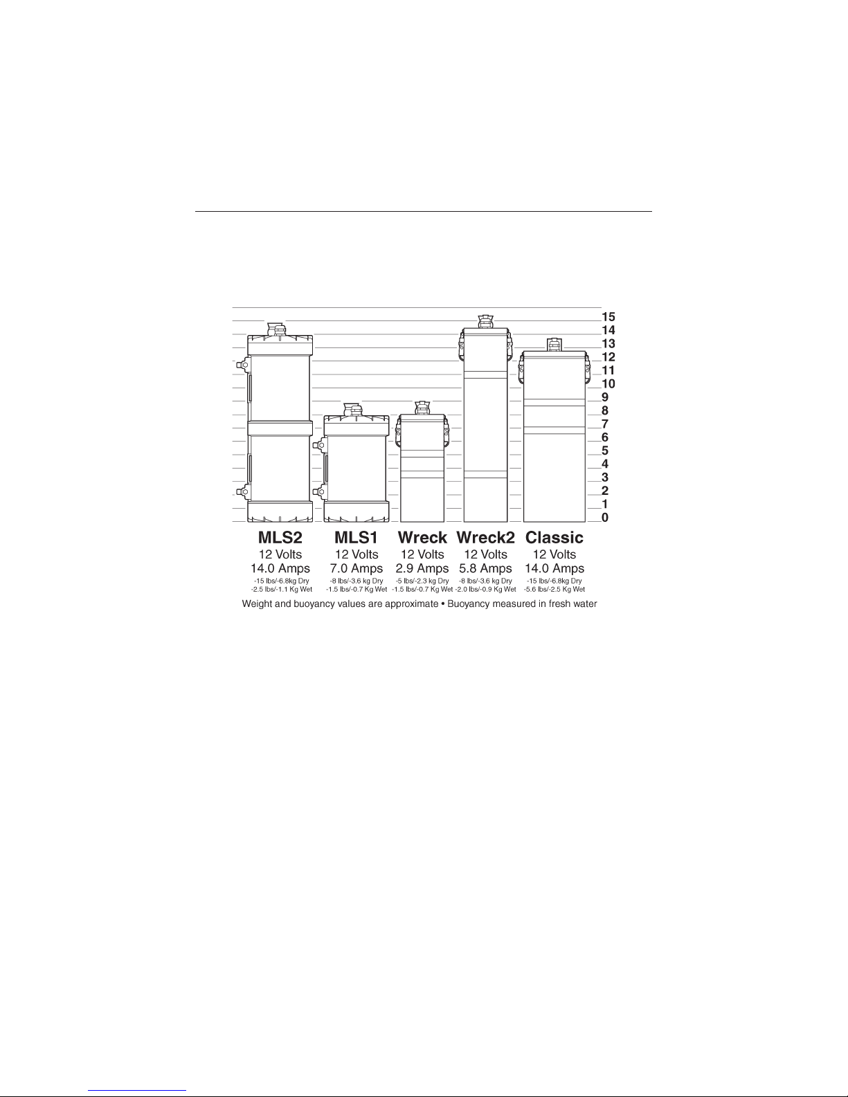
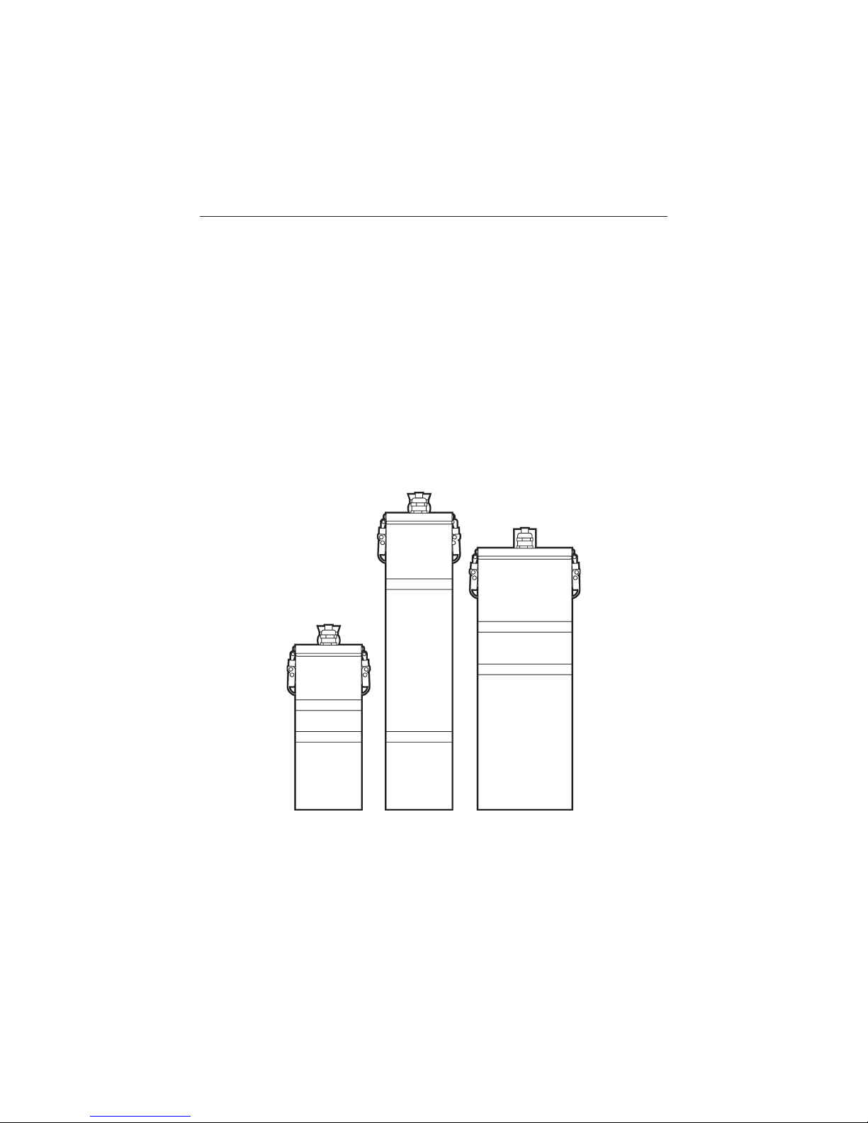
Figure 3: Dive Rite light system battery canisters.
Battery Canisters
Battery canisters house the power supply for each Dive Rite light system. Dive Rite
battery canisters fall into one of two types:
➤ MLS Canisters These house the power supplies for Dive Rite’s top-of-the line MLS1
and MLS2 light systems. No other Dive Rite lights offer as wide a choice of light
heads, or provide as many mounting options.
➤ PVC Canisters Dive Rite PVC canisters help meet special needs. For example, the
Wreck and Wreck2 lights provide a cost-effective alternative to bulky, hand-held
lights. The Classic Light satisfi es the needs of divers seeking a more traditional
exploration light.
Page 10
Light System Owner’s Manual Page 10
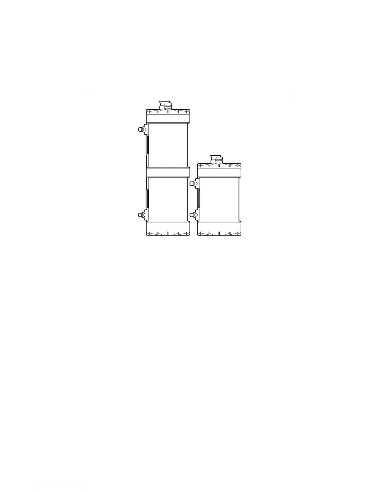
Figure 4 MLS2 (left) and MLS1 battery canisters.
MLS Battery Canisters MLS battery canister and pack combinations include:
➤ MLS2 These canisters use a battery pack containing two 12-volt/7-amp batteries,
wired in parallel to provide 12-volts at 14 amperes. In this confi guration, they can
power quartz-halogen bulbs ranging from 20 to 100 watts, for from 420 to 60
minutes, depending on bulb size.
➤ MLS1 With its compact size and diminutive profi le, the MLS1 is well-suited to
applications in which battery size and weight is a consideration. Its single 12-volt/7amp battery pack can power Compact, H1- or MR11-style HID light heads,
providing up to 300 minutes of rated “burn” time. A 50-watt bulb is standard
on quartz-halogen MLS1 lights; however, a 35-watt bulb is recommended if users
desire more than an hour of “burn” time.
On MLS2 and MLS1 lights, 50-watt bulbs are standard; however, 35-watt bulbs
are recommended if users desire more “burn” time. MLS lights are also available
with H1- or MR11-style HID light heads, providing up to 180 minutes of rated
“burn” time.
Here is a guide to the MLS canister features shown in the accompanying
illustration.
1. Canister Section MLS canisters are made from a high-strength, injection-molded,
synthetic material. It is extremely durable. Each MLS light is pressure tested at
the factory; canisters are depth rated to 500 feet/150 meters. As you have already
Page 11
Light System Owner’s Manual Page 11
seen, canister sections can be daisy-chained together, using the same O-ring seal
as is used by the lids (end caps). The design of the canister creates built-in air
spaces between the battery pack and housing. These air spaces displace water and
create lift to help offset the weight of the batteries. Without these air spaces,
the battery canisters would be up to 15.0 pounds/6.8 kg negative under water.
Because of the air spaces, the canisters are much closer to being neutrally buoy-
ant. For example, each MLS canister section, with its battery, is approximately
1.5 pounds/0.7 kg negative in fresh water — substantially less than the 8.0
pounds/3.6 kg it weighs out of water.
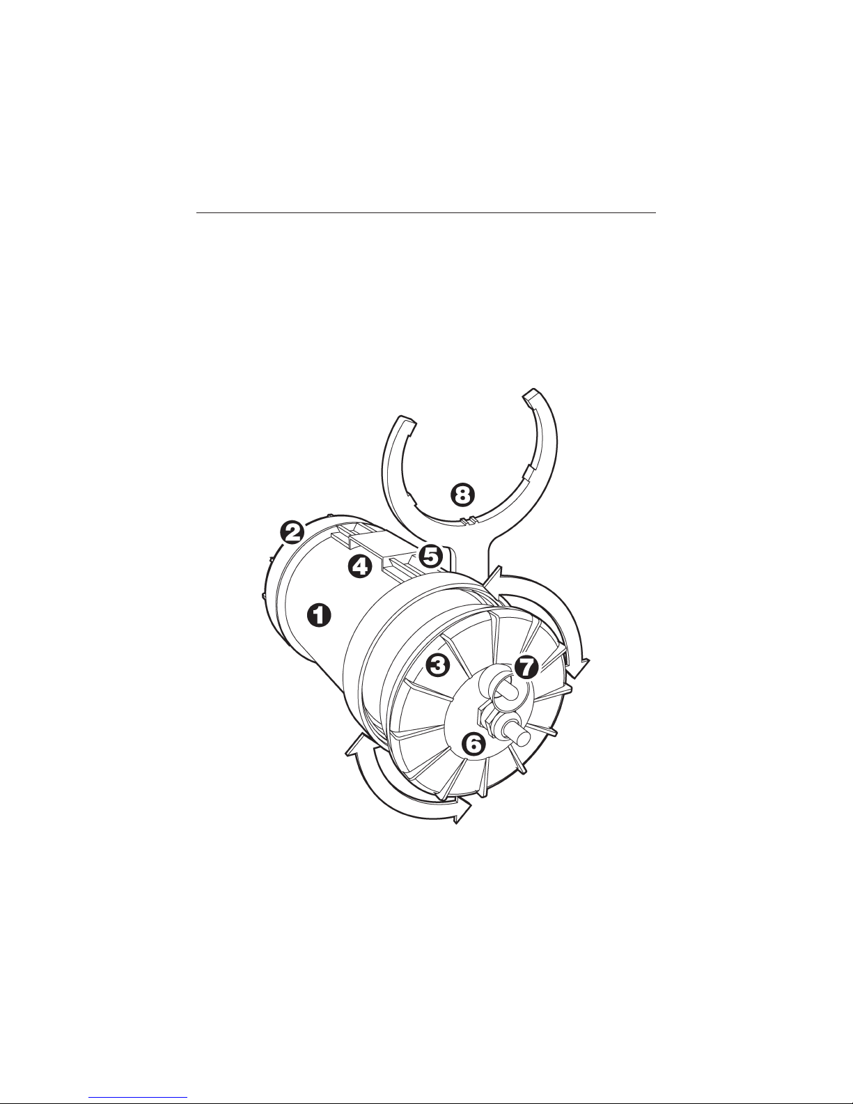
Figure 5 MLS canister features.
2. Canister Lid (Female) This lid (end cap) goes on the end of the canister opposite
the power cord. As with all canister sections and lids, it seals with a large Buna-N
Page 12

Light System Owner’s Manual Page 12
(Nitrile) O-ring. You make this seal simply by tightening the lid one quarter turn,
by hand or with the special MLS Canister Wrench described shortly.
3. Canister Lid (Male) This lid contains the sealing gland, power cord and, possibly,
the toggle switch (more on these items shortly).
4. Belt Slot The canister’s built-in belt slot accommodates standard 2.0-inch/50 mm
webbing. This allows the canister to be mounted, if desired, to weight belts,
harness waist straps, tank cam straps and similar items.
5. Dovetail Ridges The dovetail ridges on either side of the belt slot are where one
can mount the supplied attachment clamps, described below.
6. Sealing Gland and Power Cord This is what connects the battery canister to the
light head. The power cord is made from a special, heavy-duty material, designed
to stand up to the rigors of underwater use. Unlike conventional power cord
material, it is not hollow, making it diffi cult for any water that might enter a light
head or canister to travel through the power cord to other components. There
are sealing glands at both ends of the power cord. These glands help form a
watertight seal where the cord enters the canister and light head.
7. Toggle Switch The toggle switch option allows lights to be turned on and off at the
canister. You can read more about MLS switching options on page 17.
8. MLS Canister Wrench After just a few dives, divers will likely fi nd that you
can easily tighten or remove their MLS canister lids by hand. However, should
they need a little assistance removing a lid, the canister wrench (which comes
standard with every MLS1 and MLS2) provides the leverage needed to made
the job even easier.
9. Attachment Clamps A wide variety of hardware and methods are available to
attach MLS battery canisters to tanks, BCs, harnesses and other equipment. If
you are not using the built-in belt slot to attach your MLS canister to your other
equipment, you will most likely use a method that employs the MLS attachment
clamps that appear in the accompanying illustration. These clamps can be used
in conjunction with D-rings, quick links, snaps and a variety of other hardware.
They are a standard item on all MLS systems.
Page 13
Light System Owner’s Manual Page 13
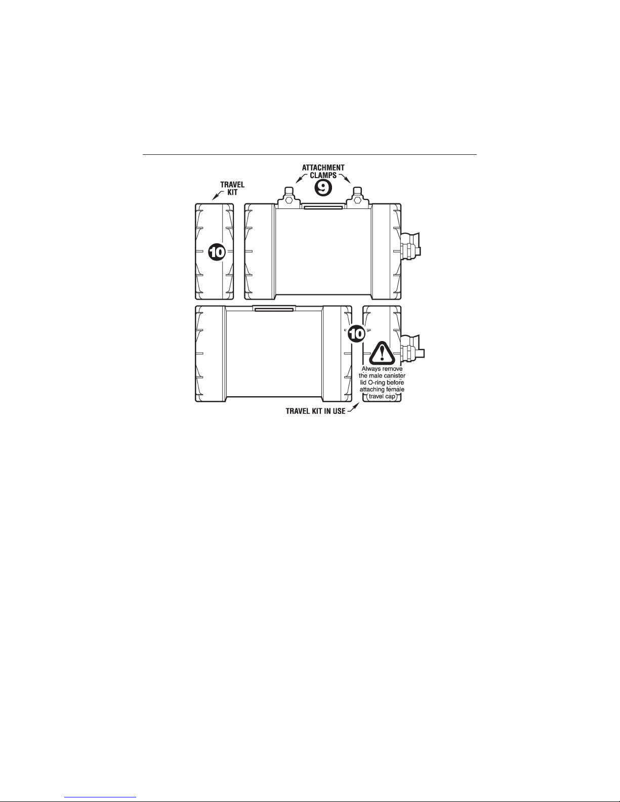
Figure 6 Additional MLS battery canister features
10. Tr av el Cap As discussed later in this manual, it is important you do not transport
your MLS1 or MLS2 with the battery connected. Doing so can result in
accidental activation of the light, which in turn can cause fi re or damage to
expensive equipment, due to the high temperatures at which the light’s quartz
halogen bulbs burn.
Additionally, you should not transport an MLS canister with the battery
inside and both canister lid O-rings in place. Doing so could allow a potentially
dangerous build-up of hydrogen gas over time.
It might seem you could avoid these problems simply by transporting MLS
batteries separate from their canisters. Unfortunately, doing so would leave a
battery pack’s connector strips exposed, and subject them to accidental shorting.
The better way to avoid these problems is to use the MLS Travel caps, shown
in the accompanying illustration. These are included with each MLS1 or MLS2.
The MLS Travel Caps consist of plain, gray male and female MLS canister lids.
(These are designed solely for surface use and cannot be taken under water.)
During transit, use the plain male lid (minus O-ring) to keep the battery pack
safely inside the canister body. At the same time, mate the plain female lid
to the male lid with the light cord, thus better protecting its contact points.
Page 14
Light System Owner’s Manual Page 14
Additionally, divers can use the small container created by joining a male and
female canister lid to store O-rings, silicone lubricant, bulbs and other spare
parts.
PVC Canisters The three available PVC canister models (Wreck, Wreck2 and
Classic) are formed from a single piece of extruded poly-vinyl chloride pipe. This
is the same material used to construct custom-made diver propulsion vehicles for
deep exploration dives. It makes an excellent pressure vessel — one that does not fl ex
at depth (and thus require battery pack bulkheads to keep the mounting hardware
from coming loose). PVC canisters are rated for depths of up to 400 feet/120 meters.
Among PVC canister features:
➤ PVC canister lights share many features in common with the MLS1 and MLS2
canisters. These features include: the use of special, solid-core power cords; and,
the use of special non-corroding sealing glands designed specifi cally for underwater
use.
Figure 7 Wreck, Wreck2 and Classic lights.
➤ PVC canisters seal using conventional quick-release latches (no special tools
required) and thick, highly-compressible O-rings. These make especially easy to
achieve an effective, water-tight seal.
Page 15

Light System Owner’s Manual Page 15
Here is additional information on each of the three PVC canister models:
➤ Wreck Light The Dive Rite Wreck Light is designed to provide a cost-effective
alternative to bulky, hand-held rechargeable lights. It gives divers the power of a
belt-, harness- or tank-mounted battery canister, combined with the freedom of a
light head that, while ultra-compact in size, provides illumination that equals or
exceeds that of nearly all top-of-the-line hand-held dive lights. Wreck lights come
with an mounting loop for 2.0-inch/50mm webbing.
Equipped with a 10-watt Compact HID light head, the Wreck Light canister
can provide up to a maximum of two hours of “burn” time. The standard quartzhalogen light head for this canister contains a 20-watt MR-11 bulb, providing up to
60 minutes of rated “burn” time from the light’s 12-volt/2.9-amp battery pack (this
is the maximum recommended wattage for this light). Sixty minutes of “burn” time
is also available when using the H1-style or MR11-style HID heads.
➤ Wreck2 Light This two-battery version of the Wreck Light is ideally suited for divers
for whom canister length is not as much of a concern as overall canister bulk
(diameter). A special mounting strap facilitates waist, tank or harness mounting.
The Wreck2 Light is available with H1, MR11 or MR16 quartz-halogen light
heads, of with H1- or MR11-style HID light heads. The standard 35-watt quartz-
halogen bulb provides up to 90 minutes of rated “burn” time from the 12-volt/5.8-
amp battery pack; 120 minutes of “burn” time is available with the HID light
heads.
➤ Classic Light The Classic Light is designed to meet the needs of divers seeking a
more traditional exploration light. It is available with H1, MR11 or MR16 quartz-
halogen light heads. The Classic Light’s standard 50-watt bulb will provide up
to 150-180 minutes of rated “burn” time from the light’s 12-volt/14-amp battery
pack. The standard mounting loop facilitate attachment to waist straps or other
2.0-inch/50mm webbing.
Batteries
Battery Type All Dive Rite light systems use sealed, lead-acid batteries (also known
as gel cells). In comparison to NiCad batteries, sealed lead-acid batteries are largely
maintenance free. After each dive, you simply connect them to their charger, plug the
charger into a wall socket, and allow them to fully recharge. It does not matter how
much or how little you used a lead-acid battery during a dive. It will not develop a
memory of a particular dive time. In fact, the only way you can seriously harm a gel
cell battery is to do the very thing you must do to maintain a NiCad battery; that is,
fully or nearly fully discharge it (a condition known as deep discharge). If you ever see
your bulb take on a yellowish appearance, turn it off immediately. Failure to do so can
severely damage the battery and charger, and substantially shorten their life.
Page 16

Light System Owner’s Manual Page 16
Better yet, consult the “burn time” chart appearing on page 45, and keep light
usage well within the times shown for the battery and bulb you are using. Doing so
will greatly extend battery life.
In summary, lead-acid batteries—while slightly heavier than their NiCad
counterparts—are considerably less of a headache to live with. They enable you to
spend your time between dives relaxing, rather than staying up late to do battery
maintenance.
Battery Packs Depending on the unit chosen, a canister will contain one or two
12-volt batteries, assembled into a single battery pack. All Dive Rite battery packs
have user-replaceable fuses so that, in the event of an accidental short or reversal in
polarity, the fuse will blow before battery damage takes place.
Figure 8 MLS1 and MLS2 battery packs.
➤ MLS1 and MLS2 battery packs reside in special MLS battery carriers. These
carriers have contact strips along the top, so that simply by sealing them inside
their respective canisters, the batteries are automatically connected and ready to
be switched on.
Page 17

Light System Owner’s Manual Page 17
Figure 9 Wreck, Wreck2 and Classic Light battery packs.
➤ PVC light system battery packs (Wreck Light, Wreck2 and Classic Light) are self-
contained and utilize a standard, two-pole “trailer plug” connection. These are
more resistant to saltwater corrosion than “banana” plugs and, unlike banana plugs,
are readily available from auto-parts and electronics stores, even in remote areas.
Switch Mechanisms
Dive Rite light systems incorporate one of two different switch mechanisms. They
are:
➤ A toggle switch…
➤ …and an actuator head.
Toggle Switch A toggle switch is a simple on/off switch mounted on the male
battery canister lid. It is ideally suited for on-camera video lights and light heads
that are normally kept in a helmet mount. In these instances, it is generally easier to
activate a toggle switch than it is to remove the light head from its holder to turn it
on. The battery canister and toggle switch, however, must be within easy reach of the
diver for this system to be effective.
Dive Rite uses special, environmentally sealed toggle switches in its lights.
This way, if any hydrogen gas escapes from the battery, the toggle switch will
minimize ignition potential. Outside the canister, a switch guard helps protect
against accidental activation.
Actuator Head To activate a light system with an actuator, you simply twist the light
head clockwise while holding on to its base. This is particularly benefi cial when the
battery canister is mounted next to or below a diver’s tank(s)—in which case getting
to a canister-mounted toggle switch would be diffi cult. An added benefi t of actuator
heads is that they enable divers to quickly switch from one type of light head to
another—in the fi eld—without special tools. Many users own two or more actuators,
so that they always have the one best suited to their next dive. Actuator mechanisms
are available on MLS quartz-halogen H1 and MR16 light heads only.
Page 18

Light System Owner’s Manual Page 18
Figure 10 To ggle and actuator switch light heads.
Light System Packages
Dive Rite light system components are available in convenient packages that include:
➤ Battery canister.
➤ Light head.
➤ Choice of switching mechanism (when available).
➤ A 115 or 230-volt AC battery charger.
Item numbers for these packages are as follows:
Wreck Wreck2 Classic
MLS1 MLS2 Light Light Light
Compact HID (Toggle) MLS1/Compact HID WRECK1/Compact HID
H1 HID (Toggle) MLS1/HID-18 WRECK2/HID
MR11 HID (Toggle) MLS1/HID-MR11 WRECK1/HID-MR11 WRECK2/HID-MR11
H1 Quar tz Halogen (Actuator) MLS1/H1.A MLS2/H1.A
H1 Quartz Halogen (Toggle, Short) MLS1/H1.TS MLS2/H1.TS WRECK-H1 Classic-H1
MR11 Quar tz Halogen (Toggle) MLS1/MR11.T MLS2/MR11.T WRECK1 WRECK2-MR11 Classic-MR11
MR16 Quartz Halogen (Actuator) MLS1/MR16.A MLS2/MR16.A
MR16 Quar tz Halogen (Toggle) MLS1/MR16.T MLS2/MR16.T WRECK2-MR16 Classic-MR16
Page 19

Light System Owner’s Manual Page 19
Light System Accessories
A wide variety of accessories are available for the Dive Rite light systems. They
include:
➤ Spare batteries and chargers.
➤ Helmets and helmet light holders.
➤ Hand mounts.
Additionally, Dive Rite makes a number of accessories that adapt light components
for underwater video applications, such as wide-angle Lumidyne refl ectors for H1
light heads, high-color temperature MR16 bulbs, wet-pluggable power cords, and
more.
Spare Batteries and Chargers Dive Rite lighting systems come standard with a
battery pack and 12-volt charger. Many light system users purchase a second battery
pack and charger. This way, they always have a second battery ready to for the next
dive. Item numbers for these components are:
Item Number Description
6119 MLS Battery Pack, MLS1
6118 MLS Battery Pack, MLS2
6309 Battery Pack, Wreck Light
6314 Battery Pack, Wreck2
6317 Battery Pack, Classic
6024 MLS Charger, for MLS
6024 Charger, for Wreck2, Classic
6310 Charger, Wreck Light
Helmets and Helmet Light Holders Dive Rite helmets (item number 2031) are
designed to help protect wearers from head impact when riding diver propulsion
vehicles (DPVs or “scooters”) and diving in overhead environments with minimal
clearance. They are also valuable in situations in which divers need both hands free,
such as when in low visibility or artifact hunting. Quick-release helmet light holders
(item number 6125) enable users to mount light heads and back-up lights of similar
diameter to these helmets.
Page 20

Light System Owner’s Manual Page 20
Figure 11 Helmet and Helmet Light Holder
The light holder allows divers to snap these light heads and back-up lights in and
out with ease. Light holders come in very handy when scootering, surveying, lobster
hunting or in any other situation that requires hands-free lighting control.
Figure 12 Hand mounts.
Hand Mounts These enable divers to attach a light head to the back of either hand,
without interfering with that hand’s ability to perform other functions.
➤ Standard Hand Mount (item number 6126) This is a rectangular handle with a
helmet light holder attached to its top. The hand mount is popular among cave
and wreck explorers.
➤ “ Ergo” Hand Mount (item number 6126E) This is a variation on the standard hand
mount that enables users to change the angle of the hand mount, relative to that
of the light holder. Many divers feel this better conforms to the natural shape
of the hand.
The H1 “Short” head comes with an “Ergo” hand mount permanently attached to
the refl ector body. This refl ector/hand mount combination (item number 6253E) is
available separately and will work with other H1 light heads as well.
Video Bulbs and Refl ectors Video lighting options for Dive Rite light systems include
special bulbs for quartz-halogen MR16 light heads, and a special video refl ector for
H1-style quart-halogen and HID light heads.
Page 21

Light System Owner’s Manual Page 21
➤ MR16 “High Color Temperature” Bulbs The 50-watt MR16 video bulb (part
number 6266WHC) outputs light with a color temperature of approximately
4,800 degrees Kelvin—much closer to that of the sun than is typical of most
quartz-halogen bulbs. It also provide a broader beam than standard MR16 bulbs
(be aware, however, there is still something of a “hot” spot in the center). Still,
due to its inherent ruggedness, the MR16 head is a good choice if a video light
is subject to potential abuse.
Figure 13 Lumedyne Refl ector
➤ Lumedyne Refl ector for H1 MLS and HID Light Heads This special 4
3
⁄4-inch
parabolic refl ector provides a soft, even diffused light, and can also be used to
provide on- or off-camera video lighting. While the parabolic refl ector provides
a substantially broader, more even beam than MR16 video bulbs, it requires a
little extra care to avoid damage. Item number are 6270 for the MLS version, and
6270HID for the HID version.
Using Your Light System
Now that you know a little about your light system, let’s get into some of the
step-by-step procedures for using it. In this section, we will cover:
➤ Tr ansporting your light system.
➤ Charging your light system.
➤ Assembling your light system.
➤ Mounting your light system.
Ironically, the one thing we won’t spend too much time discussing is how to use
your light system under water. Presumably, you’ve taken advanced, specialty or video
courses that taught you the basics of using dive lights. If you’ve not had such training,
by all means, obtain it. Other than that, the only real instructions for using your
light system under water are:
Page 22

Light System Owner’s Manual Page 22
➤ Tu rn the light on.
➤ Point it at what you want to see (or illuminate).
➤ Tr y not to shine it in your own eyes—or anyone else’s.
That last point is the one we must take somewhat seriously. Your light system may
well be several times more powerful than any dive light you’ve used prior to this. It
can blind or impair the vision of you and others for up to several minutes. This
is certainly not safe.
You should also give thought to the impact high-intensity lighting can have
on aquatic life. If you shine your light system directly in the eyes of fi sh and other
animals, you can blind them for up to several minutes. During this time, they may
severely injure themselves by bumping into coral and rocks. They will also be a the
mercy of predators, and without much of their natural defenses.
Give careful thought to the safety and comfort of other divers, marine animals
and yourself. “Watch where you point that thing—okay?”
Transporting Your Light System
If you are like most folks, you probably did not take delivery of your light system
at the dive site, just prior to going under. You most likely picked it up at your local
Dive Rite dealer, and are now (we hope!) reading this manual before going on your
next dive trip. Thus, an immediate concern is what is the safest and best way to
transport your light system to and from dive sites and home?
The Most Important Step in Transporting (and Storing) Your Light System
This single most important step in transporting your light system is this:
Do not transport your light system with the light head and
battery connected. Doing so may substantially increase the
risk of fi re or explosion, which in turn can lead to damage to
equipment, serious personal injury or death.
Why is this important? When not immersed in water, light system bulbs get hot. Very
hot. Hot enough to start fi res, melt through plastic crates and burn holes through
expensive BCs and dive suits. Trust us, we’ve seen these things happen.
The only way to prevent them from happening is to make certain your light
can not turn on accidentally while being transported to and from dive sites and
home. To do that, you need to:
➤ In the case of an MLS canister light, disconnect the battery by removing the male
canister lid and replacing it with the male Travel Kit lid.
Page 23

Light System Owner’s Manual Page 23
➤ In the case of a PVC canister light, transport the battery inside the canister, but
leave it unplugged.
Other Pearls of Transportation and Storage Wisdom This is pretty much
common sense. Don’t pack your light system so that it can fall or be damaged by
other equipment. The H1 refl ector, in particular, likes to assume unusual shapes if
you put heavy objects on top of it. Unfortunately, none of these shapes will enhance
its performance.
Even though your light system uses sealed batteries, these batteries will still
off-gas minute quantities of hydrogen gas. Larger battery packs, in particular, will
off-gas more hydrogen than their smaller counterparts. Therefore, you should never
transport or store your light system with the battery pack sealed inside the canister in
such a manner that this gas cannot escape.
Build-up of hydrogen gas inside your light system canister
over prolonged periods increases the risk of fi re or explosion,
which can in turn result in equipment damage, serious personal
injury or death. To help prevent accidental shorting of battery
contacts when transporting or storing your light system, keep
the battery pack inside its canister, but do not seal this lid
in place with an O-ring, as doing so may prevent dangerous
hydrogen gas from venting.
Charging Your Light System
By now we assume that you’ve gotten home with your light system, but it will still
be a few days (or hours) before you have the opportunity to take it diving. Before
you take your light in the water, it is important you make sure the battery is fully
charged.
Connecting the Battery and Charger Here are the steps you want to follow next:
➤ If you have not already done so, either open your light system’s canister, so that
you have access to the battery, or remove the battery pack completely from the
canister.
➤ If yours is an MLS battery, plug the connector that comes from the charger into
the block at the top of the battery, as shown on the next page.
➤ If yours is an PVC light, mate the two “trailer plug” connectors, also shown on
the next page.
Page 24

Light System Owner’s Manual Page 24
➤ After the battery and charger are connected to one another (and only then), plug
the charger and any other necessary adapters into the wall socket
Figure 14 MLS charger set up.
Figure 15 PVC charger set up.
Page 25

Light System Owner’s Manual Page 25
There are two reasons why you should connect the battery and charger before
plugging the unit into the wall.
➤ Doing so will minimize the possibility that the connectors will short out when
the wrong connector prongs accidentally touch one another with current fl owing.
(This could damage the charger’s electronic circuitry.)
➤ You also minimize the possibility that the connectors will spark when they come
into contact with one another.
How Long to Charge How long your battery will need to fully charge will depend
on a variety of factors, including the type of charger supplied with your light. Your
charger may have instructions appearing on it that tell you to charge for a specifi c
length of time. If so, follow the instructions to the letter.
In lieu of specifi c charging instructions, your chargers may have an indicator
light. If so, leave the battery and charger plugged in until the indicator light begins
to fl icker or disappears, or changes from red to green. How long will this take? If the
battery has been used, and a more signifi cant level of discharge has taken place, it
will take longer for the battery to fully charge. Charging time for a fully discharged
battery may range from four to twelve hours or more. Also, the older your battery
becomes, the longer it may take recharge after comparable periods of use.
If you will not be using your light system for some time, you should disconnect
the battery and charger before leaving them unattended. During this time, some
slight discharge will occur. For this reason, you should reconnect the charger and
bring the battery pack back up to it full voltage every 30 days, and again just before
you take you light system on a dive.
Failure to disconnect your battery and charger before leaving
them unattended for extended periods may cause damage to
these items and increase the risk of fi re or explosion.
Assembling Your Light System
You will remember that, at the beginning of this manual, we encouraged you to not
wait until you are on the verge of diving to practice assembling and disassembling
your light system. You will discover that, with just a little bit of practice, this becomes
a simple, streamlined procedure.
Disconnecting From the Charger Obviously, you can’t take the battery with you
if it is still connected to a wall socket. To safely disconnect the battery from its
charger:
Page 26

Light System Owner’s Manual Page 26
➤ Begin by unplugging the charger from the wall socket.
➤ Then disconnect the battery from the charger.
Install the battery pack inside the battery canister body, if it is not already there.
Remember, it is important you not connect the battery to the light head until you
arrive on site and are getting ready to dive.
Figure 16 Use this procedure if you need to separate two-section canisters.
MLS Canister Assembly Once on site, your next step will be to remove, clean,
inspect and, if necessary, lubricate the O-ring found on the male battery canister lid.
This is something you should do every time you assemble the canister.
To remove the O-ring, place your thumbs on the side of the O-ring, approximately 2 inches/50mm apart. Now push your thumbs together gently. Doing so
should form a bulge. You can now grasp this bulge and use it to gently roll the
O-ring out of its groove and off the lid.
After removing the O-ring, you should clean any dirt or sediment from it by
rinsing it in a stream of hot, fresh water from your faucet. Allow the hot water to
run for several minutes. The heat of the water will help cause the silicone to liquefy,
making it easier for the water to rinse off dirt, sand and salt.
After rinsing, wipe off excess water with a lint-free cloth or allow the O-ring to
air dry. Now inspect the O-ring for cuts, nicks and any other unusual signs of wear.
Replace the O-ring, if necessary.
Lubricating the canister lid O-ring is the most important step you can take in
keeping your battery canister from fl ooding. The O-ring should be evenly lubricated
Page 27

Light System Owner’s Manual Page 27
with silicone grease until it is slightly tacky. Next, put a very thin coat of silicone
on the inside lip of the canister, where the O-ring will make contact (this will help
keep the O-ring from binding as the lid screws down. By checking your O-ring
before each use, you will help avoid a build-up of grease that could attract dirt or
other contaminants.
Once you have removed, cleaned, inspected and, lubricated the O-ring, put it
gently back in its groove on the battery canister lid, as shown below.
Figure 17 Proper canister lid O-ring position.
To close the battery canister, begin by orienting the battery contacts on the male
lid to those on the battery pack, as shown below. Do not worry about getting these
contacts backwards; the lid will only close if the contacts are oriented correctly.
Figure 18 Orienting battery contacts prior to closing the lid.
Page 28

Light System Owner’s Manual Page 28
Next, position the canister lid so that its threads make contact with those of the
canister body. Turn the lid back and forth until you fi nd the point at which the
threads allow you to push the lid as far as possible into the canister, without actually
screwing it in place.
Figure 19 To seat the lid, prior to turning it, push down evenly on both sides with
your thumb.
To make sure that the lid will screw in smoothly, push down with both thumbs,
as shown above. If the lid is properly seated, you will have approximately the same
amount of gap between the lid and the canister body as shown on the next page.
Now tighten the lid by turning it one-quarter turn clockwise. When your light
is new, you may need to use the canister wrench the fi rst few times you tighten the
lid (this all but guarantees you will also need the wrench to remove the lid). After this,
you should only need to hand tighten the lid to make a good seal; using the MLS
canister wrench unnecessarily will only make the canister harder to open. If you have
diffi culty tightening the lid, try re-seating it as shown in Figure 19. It may also help
to apply a light coating of silicone grease to the canister lid threads.
If you have installed the lid correctly, you will know it; it will simply “feel”
right. If it does not feel entirely right, try repeating the steps outlined here. With
practice, you will discover that installing the canister lid quickly becomes a simple
and fairly straightforward procedure.
Page 29

Light System Owner’s Manual Page 29
Figure 20 The correct amount of gap between the lid and canister body, both just before
(left) and after (right) tightening.
PVC Light Assembly This is a fairly straightforward operation (see illustration, next
page). The steps are:
➤ Remove and inspect the canister lid O-ring. Remove any dirt or grease by rinsing
the O-ring in warm, soapy water, then drying with a lint-free wipe. Make certain
the seating surfaces on the canister and lid are equally clean.
➤ If the O-ring appears abnormally dry, apply a very light coating of silicone grease.
Use only enough grease so that the O-ring has a dull sheen. Excess grease will
only serve to attract dirt.
➤ Replace the O-ring on the canister lid.
➤ Plug the connector coming from the canister lid into its counterpart on the battery
wiring harness.
➤ Tu ck the connectors and wiring harness inside the canister, along with the foam
spacer that keeps the battery from moving around, if one was provided with your
light.
➤ Use the latches to close and seal the lid. As you do, be sure to push down on both
latches simultaneously, to help ensure you put pressure on the O-ring evenly.
Page 30

Light System Owner’s Manual Page 30
Figure 21 PVC light assembly.
H1 Lens Inspection Dive lights equipped with HI heads (both quartz-halogen and
HID models) require a further step. Prior to taking these lights under water, remove
the refl ector and make certain the base of the lens (test tube) is resting tightly against
its contact point on the metal light head body. If you detect any sort of a gap here,
push in on the top of the lens to move it back into place.
Failure to ensure that H1 lenses are in their proper position,
prior to taking a light under water, can result in serious equip-
ment damage that is not covered under warranty.
Page 31

Light System Owner’s Manual Page 31
Testing Light Operation
After closing the battery canister, you will want to check to make certain that the
light is operating properly. If your canister is fi tted with a toggle switch mechanism,
this is fairly easy. Simply move the toggle switch into the “on” position for one or two
seconds—just long enough to make sure the light is functioning correctly.
Do not attempt to test HID light operation out of the water.
When not immersed in water, HID bulbs output signifi cant UV
radiation, and can cause serious eye damage.
Additionally, once activated, HID bulbs must burn for at least four minutes, to allow
the bulb to come up to full operating temperature. If you turn an HID bulb on,
then turn it immediately off again, as you would with a quartz-halogen bulb, you
risk severely damaging the bulb.
If you own an HID light, you must accept the fact you can only test its
operation as you enter the water, or immediately prior to descending. Once your
HID light is turned on, leave it on until the end of the dive.
Even with quartz-halogen lights, you should not let your light system burn
out of water, except for brief intervals to check light function. Extended out-of-water
burn time can damage the light.
Figure 22 Actuator head orientation.
Page 32

Light System Owner’s Manual Page 32
Actuator Head Testing/Operation If your light system is equipped with an actuator
head, you will want to familiarize yourself with its on/off positioning before entering
the water. The illustration on the previous page shows which way to rotate the
actuator to turn the light on and off. If you look straight down at the tip of the
actuator, clockwise is “on;” counter-clockwise is “off.”
Rotate the actuator until the light comes on. Now back off one-quarter turn.
If you forget which way is “on,” under water, rotate the actuator no more than a
half-turn in either direction. If the light fails to come on, rotate it no more than a full
turn in the opposite direction to see if it illuminates.
Under no circumstances rotate the actuator more than one full
turn under water, without being absolutely certain you know
which direction is on and off. If you continue to rotate the
actuator in the wrong direction, you will eventually remove
it and water will fl ood the sensitive connection points inside.
This can seriously damage the light.
Conversely, you should never tighten the actuator until
it can no longer turn. Doing so may jam the two actuator
components together so hard they cannot be unlocked. It is only
necessary to turn the actuator one-quarter turn past the point
at which the bulb comes on.
Also, on the H1 head, do not use the refl ector adjustment screw as leverage to turn
the actuator on and off. Doing so may cause the adjustment screw mounting to
break. If the actuator does not turn easily, the O-rings or threads probably need
lubrication. See page 38 for more information on actuator O-ring lubrication.
Mounting Your Light System
Before taking your light system under water, you will have to determine the best
way to mount the battery canister to the rest of your equipment. There are a nearly
infi nite number of ways to do this. This section will cover some of the most common
mounting techniques, including:
➤ Waist and tank mounting.
➤ Tr anspac mounting.
Dive Rite sells a wide variety of snaps, clips, D-rings and other mounting hardware
to facilitate the process.
Waist Mounting All Dive Rite light system canisters are equipped with a loop or
slot for waist mounting. If your tank harness utilizes an exposed, 2.0-inch/50 mm
Page 33

Light System Owner’s Manual Page 33
waist strap—or you have suffi cient room on your waist for an additional 2.0-inch/50
mm waist strap—you can simply slide this strap through this loop or slot. (A special
adapter, part number 6299, is available for waist mounting MLS2 canisters; this
adapter places a waist-band slot at the mid point between the two canister sections.)
Figure 23 Wa ist mounting MLS canisters.
As shown in the accompanying illustrations, to keep the light system from sliding
back and forth on this strap, you can use an additional two-inch quick-release buckle
to lock the canister in place.
Page 34

Light System Owner’s Manual Page 34
Figure 24 Wa ist mounting PVC light canisters.
Tank Mounting Yo ur light system waist mounting loop/slot can also be used to
attach it to 2.0-inch/50 mm tank cam straps. This method is well suited to divers
using single cylinders.
When tank mounting a light system canister, try to keep the battery pack as
close to the body as possible, so as not to throw off your center of gravity. Some
BC tank bands are not well suited for tank mounting light system canisters. If yours
is among these BCs, you may be able to solve the problem by using a separate
2.0-inch/50 mm tank strap (part number 2032), just to hold the light to the tank.
Transpac Mounting If you own a Dive Rite Transpac, you can also use two of the
six, 1.0-inch/25 mm D-rings on the back side of the BC to attach your light to, as
shown in the accompanying illustrations.
Page 35

Light System Owner’s Manual Page 35
Figure 25 One method of attaching MLS canisters to Dive Rite Transpac harnesses/
Some of the hardware you use to accomplish this may include carabiners, doubleended sliding-bolt snaps and surgical tubing. Due to the wide variation in human
sizes and shapes, you will likely need to experiment to fi nd the ideal combination of
mounting hardware. When you get it right, however, the canister will seem to fl oat in
the “valley” between your Transpac air cell and the side of your body.
Figure 26 Attaching PVC light canisters to Dive Rite Transpac harnesses.
Page 36

Light System Owner’s Manual Page 36
Figure 27 Wreck2 lights have special attachment strap which can be used for waist, tank
or Transpac mounting.
Attaching Clips to Light Heads In addition to mounting their battery canister to
waist straps, BCs or tanks, most light system users attach a small snap to the light
head, so that they can clip the head to a D-ring on their BC or tank harness when
it is not in their hand.
Maintaining Your
Light System
Having invested in your light system, you undoubtedly want it to last. This section
covers how to care for your light system so that it gives you years of relatively
trouble-free service. In this section, we will discuss:
➤ Post-diving maintenance and care.
➤ Changing actuators.
➤ Changing or replacing bulbs.
➤ Making batteries last.
➤ Dealing with fl ooding or other damage.
As we mentioned earlier, if you have questions whose answers you cannot fi nd in this
manual, contact your local authorized Dive Rite dealer, or contact Dive Rite directly,
using the information appearing on the front cover.
Page 37

Light System Owner’s Manual Page 37
Post Dive Maintenance and Care
Immediately upon surfacing from every dive, perform the following steps:
➤ Inspect your light system for signs of leakage or other damage. (Your light system
may have continued to function normally, even though water was inside.)
➤ Rinse the unit thoroughly in fresh water and allow it to dry.
➤ Open the canister lid. After doing so, remove the O-ring and store it separately
(this will allow hydrogen gas to escape during transit). One convenient place to
store MLS canister O-rings is to wrap the O-ring twice around the batter contact
posts inside the lid). Removing canister lid O-rings further helps prolong its life.
Doing so also helps ensure that MLS O-rings are not in place when you attach the
female travel cap to the canister lid. Were you to attach the female travel cap with
the O-ring in place, removing it later could be diffi cult.
As you can see, these steps are pretty much common sense.
Changing Actuators
Changing actuators is a very simple and straightforward procedure. The most important step is to remember to do it above water! (Okay, we’re kidding—for the most
part. Nevertheless, there are people out there who have tried to change fi lm in their
Nikonos under water, so you never know…) Here are the steps to follow:
➤ Make certain that the light head has been thoroughly rinsed and dried following
the previous dive.
➤ If you have not already done so, disconnect the battery by removing the canister lid
and putting the female travel cap in place.
➤ Unscrew the actuator head you wish replace by turning it counter-clockwise until
it comes free from its base.
➤ Carefully lift the actuator head off its base.
Once the actuator is off the base, you will notice the grounding spring wrapped
around the threads on the base.
Ta ke care not to lose this spring, or to contaminate it with
dirt or grease.
➤ Inspect the two O-rings at the base of the actuator for a build up of dirt or
sediment. If necessary, wipe this area clean with a lint-free cloth, then remove and
re-lube the O-rings.
Page 38

Light System Owner’s Manual Page 38
➤ Screw the new actuator back in place, by turning it clockwise.
➤ Re-connect the battery and test the light to make certain it turns on and off.
O-ring Lubrication Whether installing a new actuator, or simply turning your light
system on and off, the light head should turn easily. If it does not, the O-rings at the
base of the actuator most likely need lubrication. Here are the steps to follow:
➤ Remove the actuator head, following the steps outlined previously.
➤ Remove the grounding spring and put it in a safe place, taking care not to get
grease or dirt on it.
➤ Remove the two O-rings from their grooves by fi rst pinching them so a small bulge
appears, and them rolling them off the end of the actuator.
➤ Clean any dirt or grease from the O-ring grooves with a cotton swab.
➤ Wipe any excess grease or dirt from the O-rings using a lint-free cloth, then inspect
the O-rings carefully for nicks, cracks or deformities. (Replace any O-rings that
show signs of damage.)
➤ Lubricate the O-rings by placing a small dab of silicone grease (part number 2052)
on your fi nger tips and working this into the O-rings. Remember, you only want
to have enough lubricant on the O-rings so that they present a uniform, shiny
appearance. Wipe any excess grease from the O-rings with a lint-free cloth.
➤ Replace the O-rings into their grooves, taking care not to damage them.
➤ Lubricate the actuator base threads with a small dab of silicone lubricant. You
should lubricate these threads on a regular basis; however, do not wipe off the
electrically conductive, anti-seize lubricant that we install on the threads at the
factory. This should remain in place for the life of the light; apply silicone lubricant
on top of it.
➤ Put the grounding spring back in place, taking care not to contaminate it with
dirt or grease.
➤ Reinstall the actuator head by screwing it on clockwise.
The actuator should now turn easily.
Changing or Replacing Bulbs
The ability to easily change or replace bulbs is among the keys to the light system’s
versatility. In the case of quartz-halogen lights, you can switch to lower-wattage bulbs
to extend burn time, or to higher-wattage bulbs to increase light output. You can also
easily replace bulbs that no longer function due to normal wear or impact damage.
Page 39

Light System Owner’s Manual Page 39
Only quartz-halogen bulbs and 10- watt Compact HID bulbs
are user-replaceable. Both 17- and 18-watt HID lights must be
returned to Dive Rite for bulb replacement.
H1 Bulbs Here are the steps to follow to change H1 bulbs:
➤ Make certain that the light head has been thoroughly rinsed and dried following
the previous dive.
➤ If you have not already done so, disconnect the battery by removing the canister lid
and putting the female travel cap in place.
➤ Remove the refl ector from the actuator by turning the locking screw counter-
clockwise until the refl ector slides off easily.
➤ Now, fi rmly pull the glass lens (test tube) off the end of the actuator. Do not twist
the lens during this process as it may tear one or both of the O-rings. If a tear does
occur, immediately replace the O-ring. (A tear may cause the light to leak.)
➤ The bulb will now be exposed. Hold the socket fi rmly with one hand and pull
the bulb out with the other. If you plan to re-use the bulb you are removing, take
care not to get fi ngerprints on it. (Fingerprint grease will cause bulbs to burn out
prematurely.) Grasp the bulb with a lint-free cloth, if need be, to prevent this from
happening. If you do get grease on a bulb, you can clean it off with alcohol.
Figure 28 Changing H1 bulbs.
➤ Examine the bulb contacts for signs of corrosion or any other indicators that water
may have gotten into the light head.
You are now ready to install the replacement bulb. Remember to inspect the replace-
ment carefully to ensure it is the correct voltage and wattage.
➤ Remove the replacement bulb from its package. Hold the bulb with a tissue or with
the wrapper, to avoid getting fi ngerprint grease on it.
➤ Next, fi rmly push the new bulb into the socket. Be careful to not put too much
side pressure on the bulb. This excessive pressure may cause the base of the bulb
to crack.
Page 40

Light System Owner’s Manual Page 40
At this point, you are probably thinking about lubricating the
lens O-rings. Don’ t do it. The heat of the bulb is suffi cient
to evaporate the lubricant, creating so much gas pressure that
the lens pops off under water. The O-rings should be clean and
shiny—but free of any lubricant.
➤ Now clean the inside of the lens, if required, to remove any dirt or grease. Examine
the lens for chips or cracks. If any problems exist, replace the lens because, if you
don’t, the waterproof seal may fail.
➤ Now, push the lens back into its correct position on the light head. To check if
the lens is in the correct position, look to make sure that the bottom of the lens
rests against the O-ring at the base of the light head, and that the lens O-rings
are fl at against the inside of the lens (they should form a solid black line all the
way around).
➤ Next, replace the refl ector by sliding it down onto the actuator body and tighten
the lock down screw in the guide slot.
➤ Finally, reconnect the battery to the wiring harness.
Test the light to make sure it comes on. If the light does not come on, check the fuse
you’ll fi nd on the battery pack wiring harness.
Do not bypass the fuse, as doing so may cause severe battery damage. (The fuses
help protect batteries from faulty chargers.) You will fi nd fuse fi ttings located on each
battery pack wiring harness. They take standard 15-amp automotive fuses.
Changing MR16 Bulbs (Old Style) Changing bulbs on older-style MR16 light
heads (those made prior to Fall, 1998) is a little different than changing H1 bulbs.
Here are the steps to follow:
➤ Make certain that the light head has been thoroughly rinsed and dried following
the previous dive.
➤ If you have not already done so, disconnect the battery by removing the canister lid
and putting the female travel cap in place.
➤ Remove the lens from the light head by fi rst unfastening the four screws that
hold it in place. To do so, you will need a 7⁄64-inch Allen wrench (closest metric
equivalent is 3 mm). Set the screws aside, taking care not to lose any of them.
➤ Remove and inspect the O-ring that surrounds the bulb. If it is damaged, obtain a
replacement. Otherwise, set it aside for re-installation later.
Page 41

Light System Owner’s Manual Page 41
➤ The bulb will now be exposed. Pull it out a few inches from the light head, as
shown below.
Figure 29 Changing MR16 bulbs.
➤ Hold the socket fi rmly with one hand and pull the bulb out with the other (the
bulb and refl ector are one piece). If you plan to re-use the bulb you are removing,
take care not to get fi ngerprints on it. (Fingerprint grease will cause bulbs to burn
out prematurely.) Grasp the bulb with a lint-free cloth, if need be, to prevent this
from happening.
➤ Examine the bulb contacts for signs of corrosion or any other indicators that water
may have gotten into the light head.
You are now ready to install the replacement bulb. Remember to inspect the replace-
ment carefully to ensure it is the correct voltage and wattage.
➤ Remove the replacement bulb from its box. Hold the bulb with a tissue or with the
wrapper, to avoid getting fi ngerprint grease on it.
➤ Next, fi rmly push the new bulb into the socket. When doing so, rest the edge of
the socket against the side of the light head, as shown in Figure 21. Be careful
to not put too much side pressure on the bulb. This excessive pressure may cause
the base of the bulb to crack.
➤ Push the bulb back into its recessed opening. A twisting motion will help keep
the wires from interfering.
➤ Clean and lubricate the lens O-ring and put it back in place. Take care not to get
grease on the bulb or refl ector.
➤ Now clean the inside of the lens, if required, to remove any dirt or grease. Examine
the lens for chips or cracks. If any problems exist, replace the lens because, if you
don’t, the waterproof seal may fail.
➤ Re-install the lens, using the four screws you previously set aside. Lubricate the
screws with silicone grease or “anti-seize.” Then tighten the screws by hand, as far
Page 42

Light System Owner’s Manual Page 42
as they will go. Next, use your
7
⁄64-inch/3 mm Allen wrench to tighten them a few
turns at a time. Use a rotation pattern, much as you would when putting a wheel
on a car. Make sure the screws are tightened evenly all around
➤ Finally, reconnect the battery to the wiring harness.
Test the light to make sure it comes on. If the light does not come on, check the fuse
inside the battery canister. If the fuse is blown, replace it. Do not bypass the fuse, as
doing so may cause severe battery damage.
Changing MR11 Bulbs (Old Style) The procedure for changing bulbs in older-
style MR11 light heads is largely the same as previously outlined for changing MR16
bulbs. The key difference is that, where older-style MR16 lenses are held in place by
four screws, older-style MR11 lenses come off simply by unscrewing their retaining
rings like the lid of a jar.
Be aware that, where older-style MR16 lenses are siliconed to their retaining
rings, older-style MR11 lenses are not. There is also a gasket between older-style
MR11 lenses and their retaining rings that does not exist on older-style MR16
heads. When removing these items, take care not to drop or lose them. Lubricate the
retaining ring threads with silicone grease when reinstalling it.
Changing Compact HID/MR11/MR16 Bulbs (New Style) In Fall, 1998, Dive Rite
introduced a new style of MR11 and MR16 light head. Although identical to their
predecessors in term purpose and function, these new heads employ a noticeably
different method of changing bulbs.
Figure 30 Cross section of new-style MR11 and MR16 light heads.
As the accompanying illustration shows, there is an O-ring on each side of the lens.
The inner O-ring forms a water-tight seal; the outer O-ring locks the lens in place.
Page 43

Light System Owner’s Manual Page 43
Figure 31 Removing new-style MR11/MR16 lens.
To change bulbs on either of these new-style light heads, you begin by removing the
lens. To do so, pry the outer O-ring from its groove, as shown in Figure 23. Although
this particular O-ring is not responsible for making a water-tight seal, take care to
avoid cutting or nicking it.
Once this O-ring is removed, the lens should drop right out. At this point, you
can change the MR11 or MR16 bulb as outlined earlier.
The socket for the 10-watt Compact HID bulb will not move
around inside the light head; pull the bulb straight and push
it’s replacement straight in. Use caution when doing so; HID
bulbs are very expensive and not covered under warranty.
Before replacing the lens, inspect the sealing O-ring. If there is any build-up of sand,
salt or sediment, or if it lacks the slightly shiny appearance of a properly-lubricated
O-ring, remove the sealing O-ring from its groove. Clean the groove thoroughly with
a cotton swab. Wash the O-ring in soap and water, dry it with a clean cloth and apply
a light coating of silicone grease. Now place the O-ring back in its groove.
After putting the lens back in place, re-insert the locking O-ring in its groove.
The fi rst time you do, you may need to take a while to master the knack of working
the locking O-ring in place. At fi rst, there will likely be a distinct bulge, such as
appears in Figure 31. After you mash this bulge down, two smaller ones will tend to
appear in its place. Keep pushing down on these bulges until they all disappear. With
a little practice, it will become easy.
Page 44

Light System Owner’s Manual Page 44
Making Batteries Last
Dive light batteries will not last forever. Nevertheless, with conscientious care, they
can power dive lights for dozens of dives before needing replacement. If you use
Dive Rite light systems, it is important you understand the steps you must take to
prolong battery life. If you sell Dive Rite lights, it is important you help educate your
customers about these important steps. Just how long a dive light battery will last
depends on a variety of factors, including:
➤ Has the Battery Been Completely Discharged? Doing so will utterly destroy a gel-cell
battery, such as those used in Dive Rite lights — even if the battery is brand
new. These batteries are not NiCads; they will not develop a “memory” if not
completely discharged. Completely discharging a battery will only serve to destroy
its usefulness and void warranty coverage.
➤ Has the Battery Been Drained Below 10.5 Volts? This is the point at which a quartz-
halogen bulb’s output turns noticeably yellow. Continuing to use a dive light
beyond this point will seriously damage the battery and is nearly as bad a thing to
do as completely draining the battery. As soon as a diver sees his or her dive light’s
bulb go yellow, he or she must turn it off immediately to prevent further damage.
Better yet, divers should keep light use well within the expected “burn” time, to
prevent such an occurrence. (More on this shortly.)
➤ Has the Battery Been Properly Charged? A battery must be fully recharged immedi-
ately after use, then at least once every 30 days and again prior to use.
➤ How Old is the Battery? Battery life will diminish over time, regardless of whether
the battery is used. A three-year-old battery with 30 dives on it will most likely not
provide the burn time that a six-month-old battery with the same number of dives
will — even if properly maintained.
➤ Has the Light Been Properly Assembled? Flooding can result in all sorts of dive light
damage — including damage to batteries. All Dive Rite light systems are pressure
tested at the factory prior to delivery. When light systems are returned to Dive
Rite for warranty service, the fi rst thing we do is assemble the light precisely as
outlined in the owner’s manual, including proper lubrication and installation of
O-rings. We then pressure test the light, just as we did when new. If the light
passes this second pressure test, we have to assume that any reported fl ooding must
have resulted from failure to properly assemble the light as outlined in the owner’s
manual — in which case no warranty coverage is provided.
Page 45

Light System Owner’s Manual Page 45
Among the greatest factors affecting battery life is how far you keep actual battery use
within the battery’s expected burn time. If divers consistently use their batteries for
close to 100 percent of the expected burn time, battery life will be relatively short.
Color Wreck Light Wreck2 MLS1 MLS2/Classic
Temperature Average Expected Expected Expected Expected
Part in Degrees Bulb Life Burn Time Burn Time Burn Time Burn Time
Number Wattage Kelvin in Hours in Minutes in Minutes in Minutes in Minutes
HID Bulbs
Compact) 10 6000 1100 120 300
6315 (MR11) 17 6500 1100 60 120 180 360
6302 (H1) 18 6500 1100 60 120 180 360
MR16 Bulbs
6106 20 2950 3500 60 110 210 420
6128 35 2950 3500 90 120 240
6107 50 2950 3500 50 60 150
6107HC 50 4800 3500 50 60 150
6266 501 4800 3500 50 60 150
6266WHC 502 4800 3500 50 60 150
6108 75 2950 3500 45 100
6135 1003 3350 50 35 60
MR11 Bulbs
6226 20 2950 2000 60 110 210 420
6225 35 2950 2000 90 120 240
H1 Bulbs
6293 20 2850 2000 60 110 210 420
6283 35 2900 2000 90 120 240
6132 50 3300 50 50 75 180
6133 100 3300 50 35 60
1. Special high-color-temperature bulb (10° spot); works only with newer-style heads
2. Special high-color-temperature bulb (wide-angle); works only with newer-style heads
3. Special wide-angle video bulb
Page 46

Light System Owner’s Manual Page 46
On the other hand, if users keep actual battery use well within expected burn times,
battery life can be dozens upon dozens of dives — potentially exceeding 100 or
more dives. The table on the preceding page will help you determine the expected
burn time of a dive light when new. The times listed represent average maximum
expected burn times for new batteries in good condition. You should bear in mind,
however:
➤ We base the information appearing here on data supplied by the batteries’ manufac-
turer, and upon our own tests of how long it takes a properly charged battery,
under load, to reach an output of 10.5 volts. Battery manufacturers, however, may
change product specifi cations at any time, without warning. As a consequence the
information appearing here may not be true in the future.
➤ Batteries are not manufactured to the same tolerances as machined parts. New
batteries can easily provide more or less potential burn time than appears here.
(Which is one more reason to keep actual use well within rated burn times.)➤
Potential burn time will diminish over the life of the battery. You should not
assume that a battery which has been used several times, or which is more than
a few months old, will have the same potential burn time as a battery that is
brand new. (Information on how to “burn test” dive light batteries is available
from Dive Rite’s website.)
➤ HID bulbs do not diminish in output as the battery drains. They will continue
to output light of the same color temperature and intensity until the battery
drains to approximately 7.5 volts. At this point, the light will abruptly shut
down. Unfortunately, this will occur after serious battery damage has taken place.
Therefore, it is essential users not take their HID lights past, or even close to the
rated burn time, as the bulb will provide no warning of potential battery damage.
Dive Rite warranties batteries for 90 days against defects in workmanship and
materials. This means problems such as broken terminals — not loss of burn time.
Loss of burn time is something that results exclusively from misuse or neglect; it is
not covered under warranty.
Attempting to charge batteries damaged by overuse or abuse can cause permanent damage to battery chargers. Attempting to charge a new battery with a damaged
charger can further cause damage to the new battery. Neither situation is covered
under warranty.
Dealing with Flooding or Other Damage
Flooding. As the bumper stickers say, “It Happens.” (Or words to that effect.)
Obviously, you can minimize or eliminate the risk of fl ooding by following the
procedures outlined in this manual. Still, not everything unpleasant in life is totally
avoidable.
Page 47

Light System Owner’s Manual Page 47
At times, the signs of fl ooding are obvious. You open you battery canister and
several pints or litres of water fall out. You notice your light dimming during a dive
and, upon examining the lens, fi nd it fi lled with water.
Signs of fl ooding may also be subtle. You notice water droplets where they do
not belong when changing actuators. There is condensation on the inside of your
lens. You see corrosion on the prongs of the bulb you are changing.
If you have reason to suspect fl ooding, do not continue to use the light.
Arrange with your dealer to send it back to Dive Rite immediately for repair. Flooding damage is not something that can be corrected in the fi eld. Continuing to use the
light can make things substantially worse.
Dealing with a Catastrophic Flood A catastrophic fl ood is when your canister or
light head contains more than just signs of moisture. This type of fl ooding means
you can open up your light and pour water out. Here is what to do:
➤ Tu rn the light off and switch to your back-up lights. The longer current fl ows, the
more damage can take place.
➤ Surface as soon as possible, but do not take unnecessary risks. (Fixing a light is
cheaper and considerably less painful than a ride in the chamber.)
➤ As soon as you can after surfacing, disconnect and remove the battery. Again, the
longer current can fl ow, the more damage can be done.
➤ Open up all parts of the light, and pour out any water. Although unlikely, may
travel up or down the light cord, so don’t assume that just because it was your
canister that fl ooded, there will be no water in the light head (and vice versa).
➤ Rinse all parts that have been exposed to fl ooding with fresh water. Take care not to
force water into parts of the light that have not been affected, however.
➤ Once you have thoroughly rinsed the affected parts, towel them dry.
➤ Before salt and minerals have a chance to crystallize, seal the affected light compo-
nents in plastic bags, so that water trapped in nooks and crannies you can’t get to
will not have a chance to dry.
Send all affected parts back to Dive Rite for repair. Don’t delay in doing so.
The good news is that fl ooding a light system is nowhere near as catastrophic
as, say, fl ooding a camera. (It is also fairly uncommon.) No matter or bad the damage
may initially appear, your light will be salvageable. The faster you act, though, the
less costly the repair bill will be.
Other Damage Dive Rite light system components are pretty rugged. Outside of
fl ooding, the only other damage that is likely to occur will result from accidentally
dropping the light head. This will usually cost you a bulb replacement, although
sometimes it will result in a cracked lens.
Page 48

Light System Owner’s Manual Page 48
If you do suspect impact damage, inspect the affected part carefully. Connect
the battery and test the light for function. Replace any cracked lenses immediately.
Be aware that older MR16 lenses may be siliconed in place, so you must replace the
lens and retaining ring as a unit.
If you have questions, contact your local authorized Dive Rite dealer, or Dive
Rite itself, using the contact information on the front cover.
 Loading...