

DITTEL S6000 Operation Manual
Installation- and Operation Manual
Covers S6000, Article Number O830L614001 (A/N F62005)
Date of Issue: May 2021
Issue: 6
Article Number: ODNFL61EN01 (D62022)
S6000
Acoustic Emission Monitoring Module
Dittel Messtechnik GmbH is certified according to DIN EN ISO 9001 and DIN EN ISO 14001
Acoustic Emission Monitoring
S6000
Installation and
Operation Manual
ODNFL61EN01 (D62022): S6000, A/N O830L614001 (A/N F62005)
This Installation and Operation Manual was originally published in German.
In case of any disputes due to the translation, the reference will be solely the
German text.
Issue
6
Valid with DSCC
Software
Version V 3.71 or later
Valid with Module
Software
Version 1.1, Build Number T0.08 or later
(see Module Mode S6000 Settings Identification)
Supplementary
documents
Programming Interface ................ A/N ODNDL03EN01 (A/N D60020)
DS6000 Proxy Service ................ A/N ODNDL03EN02 (A/N D60021)
PROFIBUS Communication ........ A/N ODNDL03EN04 (A/N D60023)
Issue
DESCRIPTION/REASON FOR CHANGE
Date
1
Translation of “Installations- und Betriebsanleitung S6000, A/N
D62012”, Issue 2, January 2009, from German into English.
April 2009
2
DECLARATION of CONFORMITY added
January 2010
3
“Series Start-up” added
April 2010
4
Acquisition of full ownership by MARPOSS S.p.A., Italy
August 2012
5
Introduction of DSCC software version 3.60, MARPOSS MHIS/P7
software integration, adaption to Windows® 7
May 2014
6
Small modifications, adaption to Windows® 10
May 2021
Before operating the unit, please read this Installation and
Operation Manual thoroughly!
Please observe the Safety Information!
Keep this document at your workplace for further use!
Manual Revision History
This list gives you a description of the last changes of the «Installation and
Operation Manual» due to new software, new hardware, mistakes, or
errors.
2 of 120 DITTEL – ODNFL61EN01 May 2021

S6000
Acoustic Emission Monitoring
Table of Contents
Manual Revision History ............................................................................ 2
Table of Contents ....................................................................................... 3
1 For Your Safety ................................................................................ 6
1.1 General ........................................................................................................... 6
1.2 Intended Use .................................................................................................. 7
1.3 Symbols used ................................................................................................. 7
2 Introduction ..................................................................................... 8
2.1 Purpose of the S6000 ..................................................................................... 8
2.2 Application of the S6000 ................................................................................ 9
2.2.1 General ........................................................................................................... 9
2.2.2 Reducing the Air Grinding Time ..................................................................... 9
2.2.3 Touch Dressing ............................................................................................ 10
2.2.4 Monitoring the Dressing Process ................................................................. 11
2.2.5 Crash Control ............................................................................................... 12
2.2.6 Example of Monitoring the Dressing and Grinding Process by means of two
AE Sensors .................................................................................................. 13
2.3 Components of an S6000 AE Monitoring System ........................................ 13
2.4 Connection of several DS6000 Modules to a S6000 Module ...................... 14
3 Installation ..................................................................................... 16
3.1 Mechanical Installation ................................................................................. 16
3.1.1 Acoustic Emission (AE) Monitoring Module S6000 ...................................... 16
3.1.2 Installation of AE sensors ............................................................................. 18
General ......................................................................................................... 18
AE sensor ‘S’ or Magnetic Type AE sensor ‘MGP1’ .................................... 19
Centre Mounted AE sensor ‘M’ or AE Ring sensor ‘R’ ................................. 19
AE Fluid sensor ............................................................................................ 20
Custom-designed AE sensors, e.g. ID sensors ........................................... 20
3.2 Electrical Installation ..................................................................................... 21
3.2.1 General ......................................................................................................... 21
3.2.2 Connector # 1, 24 Vdc Supply ..................................................................... 21
3.2.3 Connector # 2, Hardwire Interface of AE Monitoring ................................... 22
3.2.4 Connector # 5 ............................................................................................... 25
3.2.5 Connectors # 9 and # 10 .............................................................................. 26
3.2.6 Connector # 13, PROFIBUS Interface of AE Monitoring ............................. 27
3.2.7 Connectors # 21 and # 22 ............................................................................ 28
3.2.8 Ground terminal, stud M4 and hex nut ......................................................... 28
3.3 Settings before getting started ..................................................................... 29
3.3.1 Setting the DIP-Switch # 6 ........................................................................... 29
3.3.2 Rotary Decode Switches # 11 and # 12 ....................................................... 30
3.4 LED Displays while operating ...................................................................... 31
4 Dittel System Control Center Software ................................ ........ 32
4.1 General ......................................................................................................... 32
4.1.1 Hardware Requirements .............................................................................. 32
May 2021 DITTEL – ODNFL61EN01 3 of 120

Acoustic Emission Monitoring
S6000
4.1.2 Supported Operating Systems / System Requirements ............................... 32
4.1.3 Directory Structure ........................................................................................ 33
4.1.4 Running set-up program using CD-ROM or DVD ........................................ 33
4.2 Software Installation ..................................................................................... 34
4.2.1 Standard Windows® ...................................................................................... 34
4.2.2 SINUMERIK® 840D ..................................................................................... 37
PCU 50 ......................................................................................................... 37
PCU 50.3 ...................................................................................................... 37
PCU 50.5 ...................................................................................................... 37
SINUMERIK HMI Advanced ......................................................................... 40
SINUMERIK Operate .................................................................................... 42
4.3 Software Update ........................................................................................... 43
4.3.1 Changing the Installation Directory .............................................................. 43
4.4 Delete the DSCC Software ........................................................................... 45
5 General Settings ........................................................................... 46
5.1 Starting the Program .................................................................................... 46
5.1.1 Requirements to configure the RS-232 interface ......................................... 47
5.2 General Settings ........................................................................................... 48
5.2.1 General Settings: Language ......................................................................... 48
5.2.2 General Settings: Communication Parameters 1 ......................................... 51
Setting the IP Address of an Ethernet Interface Converter .......................... 53
5.2.3 General Settings: Communication Parameters 2 ......................................... 55
5.2.4 General Settings: Access Rights .................................................................. 56
5.2.5 General Settings: Menu Bar ......................................................................... 60
5.2.6 General Settings: OPC Settings ................................................................... 65
6 Module specific Settings .............................................................. 66
6.1 Precondition .................................................................................................. 66
6.2 Starting the Program .................................................................................... 66
6.2.1 Start Screen .................................................................................................. 67
6.2.2 Activating the Module(s) ............................................................................... 68
6.2.3 Module View – highlighting, positioning and scaling .................................... 71
6.2.4 Create different Display Layers .................................................................... 72
6.2.5 Delete Module View(s) ................................................................................. 73
7 Starting up ..................................................................................... 74
7.1 Prerequisite .................................................................................................. 74
7.2 Starting Up .................................................................................................... 75
7.2.1 Adjusting the Set .......................................................................................... 78
7.2.2 Adjusting the Frequency Range ................................................................... 79
7.2.3 Adjusting the Sensor Parameters ................................................................. 80
7.2.4 Adjusting the AE Signal Gain ....................................................................... 82
7.2.5 Adjusting the Offset ...................................................................................... 84
7.2.6 Adjusting the Crash Gain ............................................................................. 85
8 Automatic Operation ..................................................................... 86
8.1 Prerequisite .................................................................................................. 86
8.2 Shortening the Air Grinding Time ................................................................. 88
8.3 Monitoring the Dressing Process ................................................................. 88
8.4 Combination of “Shortening the Air Grinding Time” and “Monitoring the
Dressing Process” ........................................................................................ 89
4 of 120 DITTEL – ODNFL61EN01 May 2021

S6000
Acoustic Emission Monitoring
9 Placing the Access Rights – Series Start-up ............................... 90
9.1 Placing the Access Rights ............................................................................ 90
9.1.1 Placing a password the very first time .......................................................... 90
9.1.2 Change actual Access Level ........................................................................ 92
9.1.3 Change your Password ................................................................................ 93
9.2 Series Start-up ............................................................................................. 94
9.2.1 Creating a Series Start-up File ..................................................................... 94
9.2.2 Importing the Series Start-up File ................................................................ 95
Appendix A MHIS Software - MARPOSS Human Interface SW ............ 98
A.1 Integration of MARPOSS MHIS Software .................................................... 98
A.1.1 Requirement ............................................................................................... 98
A.1.2 DSCC Software Installation ....................................................................... 98
A.1.3 Starting the Program .................................................................................. 99
Appendix B Troubleshooting Guide .................................................... 102
B.1 Hardware Troubleshooting ......................................................................... 102
B.2 Software Troubleshooting .......................................................................... 104
B.2.1 General ....................................................................................................... 104
Message »New hardware found (serial mouse)« .................................. 104
Message »Could not connect to the destination« ................................ 104
Windows
B.2.2 SINUMERIK® .............................................................................................. 105
Pressing the softkey does not start the software, or when starting, an error
message appears: ...................................................................................... 105
®
XP / 7 / 10 Management of Rights ........................................ 104
Appendix C Cleaning, Maintenance and Environmental Protection . 106
C.1 Cleaning ..................................................................................................... 106
C.2 Maintenance ............................................................................................... 106
C.3 Environmental Protection ........................................................................... 107
Appendix D Technical Specifications S6000 ...................................... 108
Appendix E Abstract of PROFIBUS Interface S6000 .......................... 110
E.1 Data Format S6000 .................................................................................... 110
E.1.1 Control to S6000 Module (Inputs) .............................................................. 110
E.1.2 S6000 Module (Outputs) to Control ........................................................... 111
E.1.3 Truth Table to select or confirm the appropriate Memory Sets .................. 111
Appendix F Glossary – Abbreviations – Index ................................... 112
F.1 Glossary ..................................................................................................... 112
F.2 Abbreviations .............................................................................................. 114
F.3 Index ........................................................................................................... 116
Copyright – Service Information ............................................................ 118
May 2021 DITTEL – ODNFL61EN01 5 of 120

1 For Your Safety
S6000
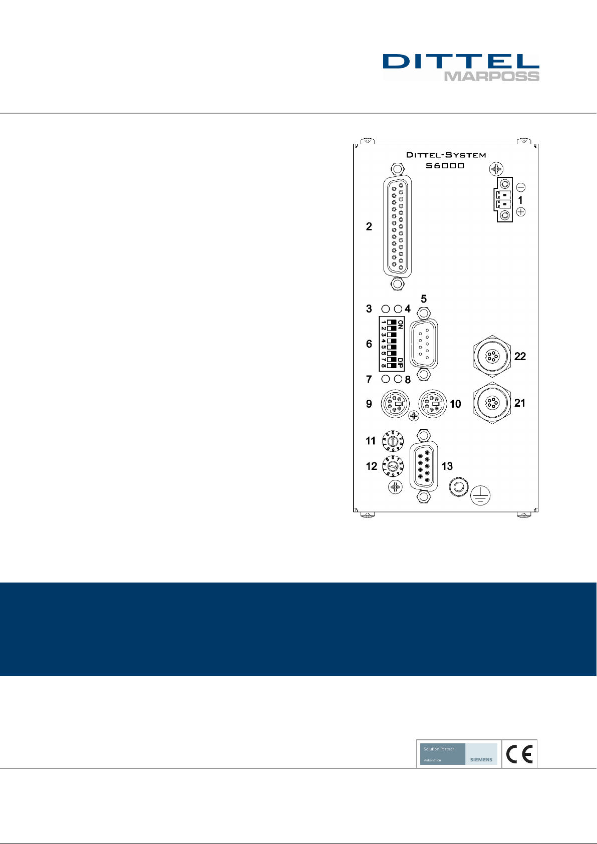
The Dittel-System S6000 is a state-of-the-art Acoustic Emission
Monitoring Module developed and produced according to
recognised safety directives, rules, standards, and regulations. To
preserve this standard and in order to maintain safety, you as a
user must adhere to this Operation Manual.
The Module S6000 must be powered from a 24 Vdc supply only!
The power source must comply with EN 60950 SELV (Safety Extra
Low Voltage). Applying a higher voltage can cause a damage of
the device.
According to EN 61010-1:2010 the 24 Vdc power lines must be
protected by a 4 amps fuse, time-lag.
NEVER operate a machine tool without all proper safety guarding
in place. Be sure to read all information and safety instructions
given by the manufacturer of the machine tool.
Switch OFF the machine tool when installing or adjusting
components of the Process Monitoring System! Be sure the
machine spindle has come to a standstill before working on it!
Secure the machine against unauthorized or accidental switching
on!
Do not put any solid objects or liquids such as water into the unit.
In case of an accident cut off the power supply. Using the unit with
any object inside may cause fire or electric shock!
Do not remove the cover. Refer servicing to qualified personnel
only!
Do not pull or bend the power cable and the signal cables.
Replace damaged cables right away! Unused ports and
connectors must remain covered with protecting ESD caps.
Only personnel ordered and instructed by the management may
operate the S6000.
The management must
- make the Operation Manual accessible to the operator and
- make sure that the operator has read and understood it.
This Operation Manual is an integral part of the Module S6000. So
if the S6000 is sold, disposed of, or rented out, always include this
Operation Manual with the S6000.
1 For Your Safety
1.1 General
6 of 120 DITTEL – ODNFL61EN01 May 2021
S6000
1 For Your Safety
Use the S6000 exclusively to monitor grinding and dressing
processes by means of acoustic emission signals!
The device is not a safety component in accordance with the EU
machine directive.
Operate the Module in industrial environment only!
The device is suitable for indoor use only.
Operate the S6000 device only with original Dittel Messtechnik
GmbH accessories.
Do not operate the device in explosive areas! Operation of the
S6000 in such an environment means an essential endangering of
safety!
Unauthorized modifications and changes of the system are
forbidden. When replacing defective parts use only original spare
parts or standard parts recommended by the manufacturer.
In this Operation and Installation Manual the following symbols can
be used:
DANGER
This warning note indicates a hazardous situation, which if not
avoided, will result in death or serious injury.
WARNING
This warning note indicates a hazardous situation, which if not
avoided, could result in death or serious injury.
CAUTION
This warning note indicates a hazardous situation, which if not
avoided, may result in minor or moderate injury.
NOTICE
This note describes particularly important application notes and facts.
Failing to observe the note may cause in property damage or an
unsatisfactorily working device.
indicates a work step which must be executed.
[ squared bracket ]
indicates soft keys or buttons on the screen or keys of the keyboard.
This font
indicates program names or commands.
This font
shows program lines.
1.2 Intended Use
1.3 Symbols used
May 2021 DITTEL – ODNFL61EN01 7 of 120

2 Introduction
S6000
This Installation and Operation Manual contains notes for the
installation, setup, and operation of the Acoustic Emission Monitoring
Module S6000 out of the Dittel-System (DS) 6000 Series.
Consistent high quality, automation, increased productivity reduction
of downtimes – these are the demands of the machine tool industry
for production processes. During grinding or dressing sequences, it is
a necessity that the process is both safe and also able to achieve
consistent work piece quality. Even when the cycle is optimised a
completely safe and trouble free run cannot be guaranteed, thus the
need to monitor the process becomes essential. The acoustic
emission (AE) signal is an ideal and safe criterion for such an
evaluation.
During a grinding or dressing process the high sensitive Acoustic
Emission Monitoring Module S6000 monitors and/or controls –
depending on use – first touch signal, touch dressing control, air
grinding time, and/or Crash Control. For use on surface, external and
internal grinding machines a variety of AE sensors are available. The
AE signal is picked up at the source – e.g. in the centre of a rotating
spindle – and fed to the unit for analysis.
Up to two AE sensors may be connected to the Module. The selection
of the AE input is carried out manually or externally by switching over
from the automation system. Using the AE function a Crash signal
(using the same AE sensor) can be displayed additionally.
All settings, display and operation of the S6000 are exclusively
carried out on a PC integrated Automation System for machine tools
or a standard PC based on Microsoft Windows®. Predefined,
individual adjustable user levels are provided like Service /
Administrator / Expert / Operator / Observer. The display window can
be specified individually as well with regard to graphic representation,
or windows width.
By additional Process Monitoring Modules S6000 it is possible to
supervise and to control many machine spindles at the same time;
complicated switching-over is dropped. Just as simple is the
extension by one or more Balancing Modules for the spindles, either
operated mechanically (M6000) or by using the coolant as balancing
medium (H6000).
The total number of all modules and control units (PC, Automation
System) is restricted to 15.
PROFIBUS and Ethernet (optional, external) are additional interfaces
besides the present serial and parallel ports.
2 Introduction
2.1 Purpose of the S6000
8 of 120 DITTEL – ODNFL61EN01 May 2021

S6000
2 Introduction
During any grinding or dressing process, the grinding wheel and
workpiece/dressing wheel both produce a noise (Acoustic Emission =
AE) whose spectral frequency distribution is, for the main proportion,
in the ultrasonic range. Additional noises, produced by components
such as gearbox, bearings, hydraulic components, etc., are mainly
composed of lower frequencies. Consequently the frequency
separation between grinding noise and machine noise is sufficient to
monitor the grinding noise only. So, when the grinding wheel touches
the workpiece or the dresser the ultrasonic level increases
dramatically and a reliable evaluation criterion is received.
During conventional grinding, the infeed speed must - for safety
reasons - be reduced to Process Grinding Speed some time before
the grinding wheel touches the workpiece.
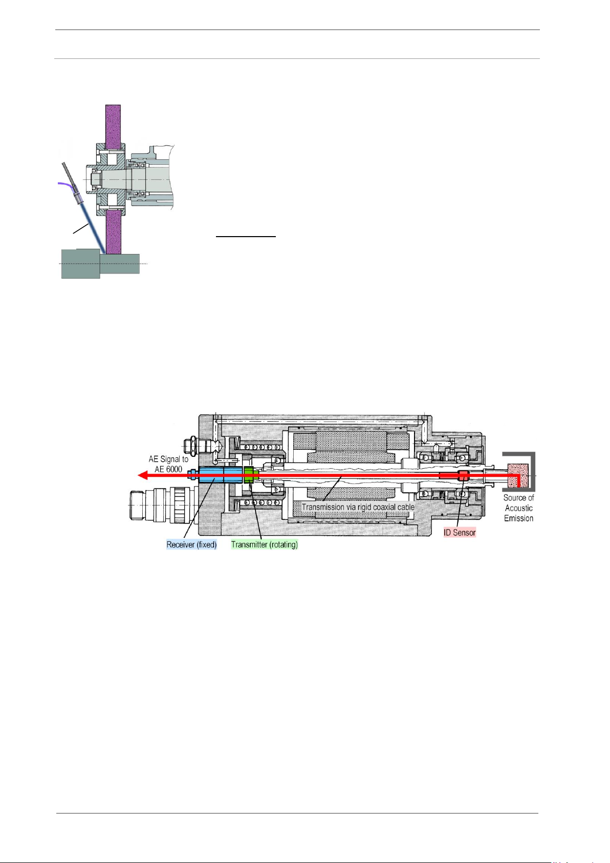
With a S6000 fitted to the machine the noise emission of the grinding
or dressing wheel is picked up by an AE Sensor which is placed e.g.
on the bearing housing and fed via cable to the electronic unit. The
AE Sensor can be placed also in the centre of the spindle nose and
connected to the transmitter at the end of the spindle. The AE signals
are fed contact free to a fixed receiver and passed on via cable to the
AE Evaluation Unit.
At the beginning of a grinding/dressing cycle the grinding
wheel/dresser is fed with rapid infeed speed to a certain safety
position to the workpiece or grinding wheel. The automation system
gives a command to change the infeed to the (slower) Air
Grinding/Dressing Speed. The AE Sensor picks up the basic machine
noise which is made visible on the screen of the automation system.
As soon as the grinding wheel/dresser touches the
workpiece/grinding wheel the Acoustic Emission (ultrasonic noise)
increases instantaneously and exceeds a pre-set threshold value.
Within 12 milliseconds the S6000 gives a LOW signal to the
automation system. This causes the automation system to reduce the
machine’s infeed from Air Grinding/Dressing Speed to Process
Grinding/Dressing Speed.
This application is suitable for surface and external cylindrical
grinding machines as well as for ID grinding and dresser spindles.
2.2 Application of the S6000
2.2.1 General
2.2.2 Reducing the Air Grinding Time
May 2021 DITTEL – ODNFL61EN01 9 of 120
2 Introduction
S6000
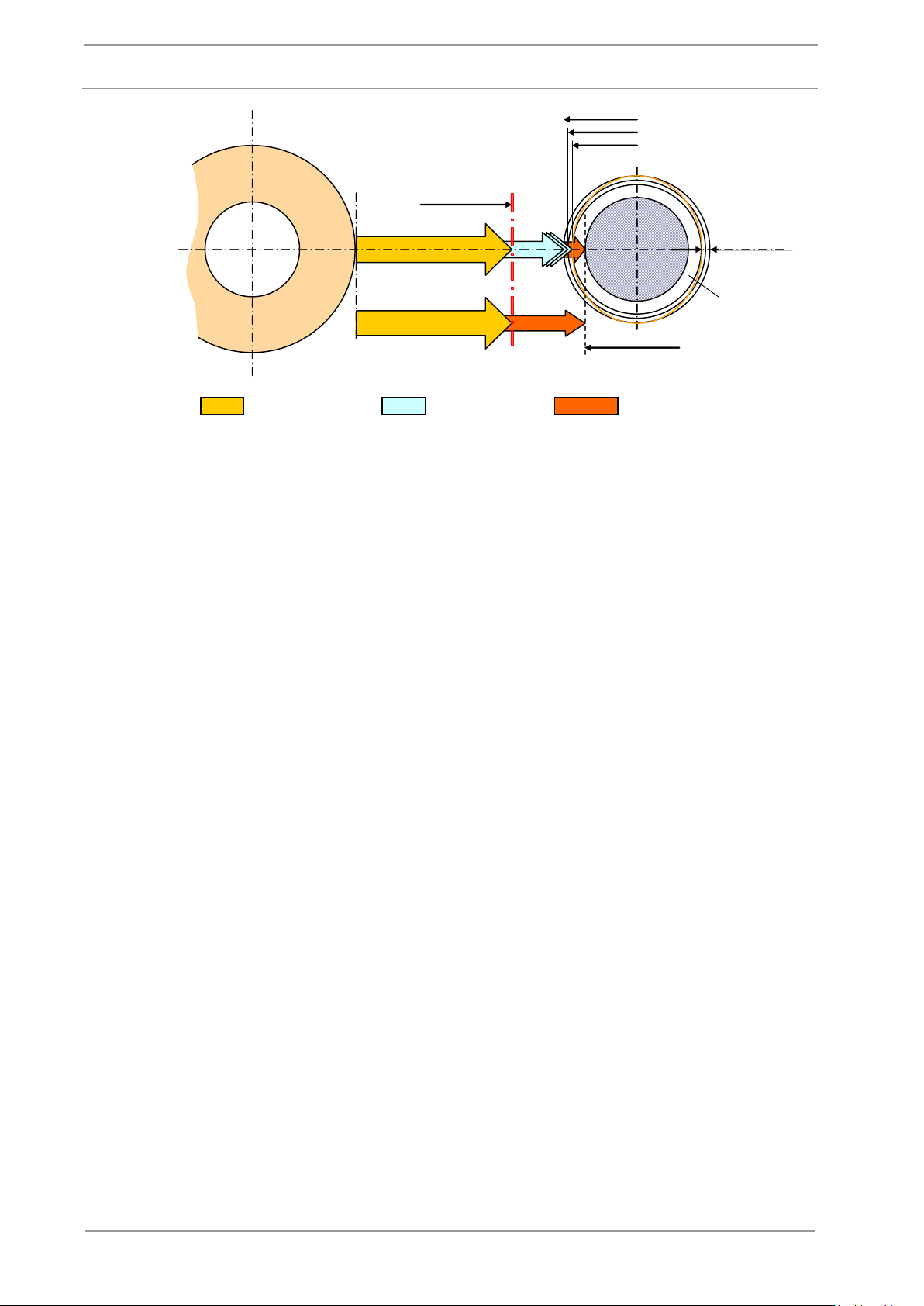
First
contact
Tolerance of
workpiece radius
Process finished
Safety Position
Workpiece
Rapid Infeed
Air Grinding Speed
Process Grinding Speed
Infeed monitored by S6000
Conventional Infeed
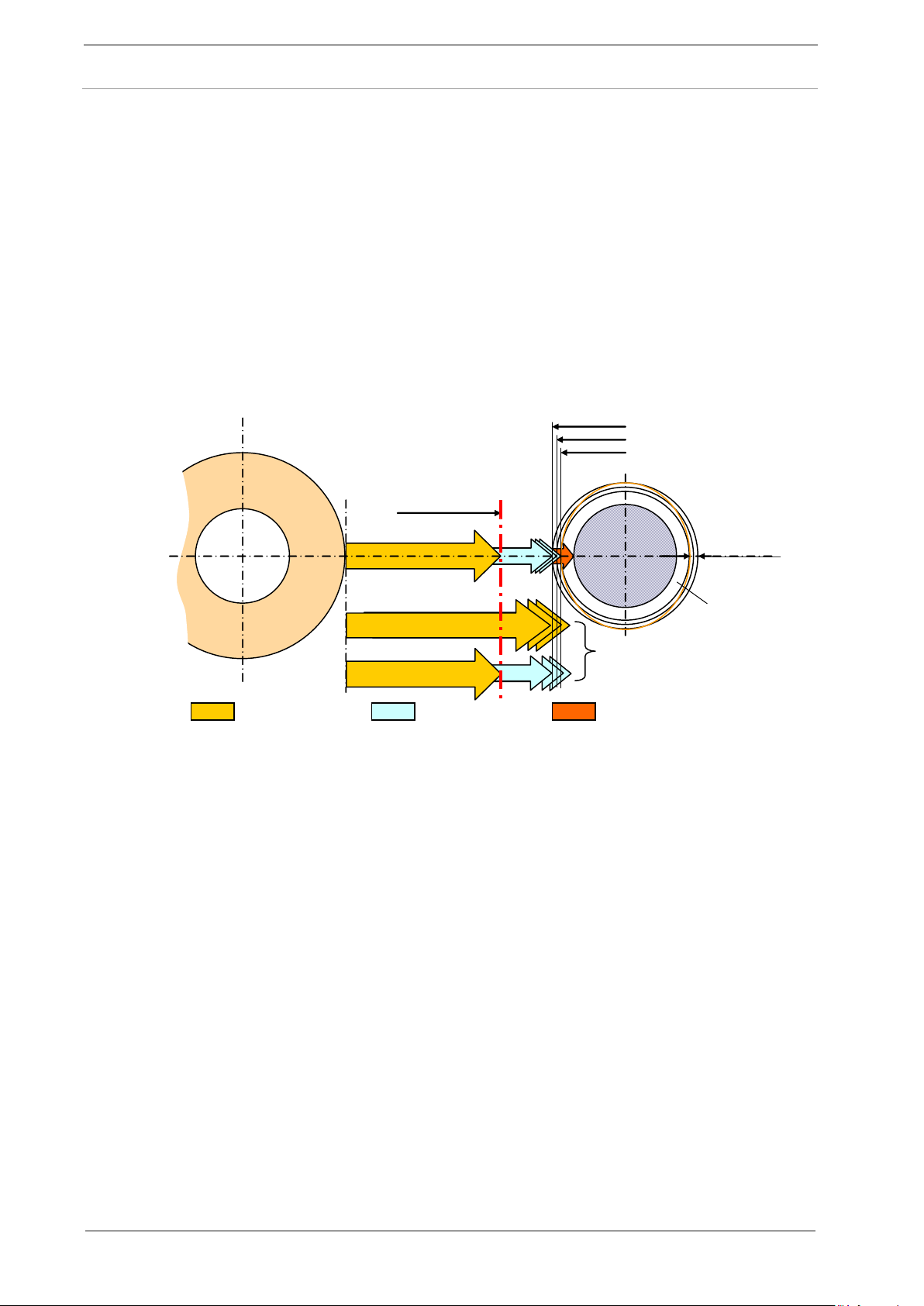
Particularly when dressing CBN grinding wheels the recognition of the
first touch is very important in order to remove as little material as
necessary. This maintains the chip space of the wheel and frequent
re-sharpening is reduced.
The sensor, mounted centrically on the rotating dresser or grinding
wheel shaft (for centreless applications the sensor can be ring
shaped), picks up the AE Signal at its source and transmits it to the
fixed receiver unit. This technology considerably increases the
grinding noise against the machine noise ratio, and consequently
improves the safety of the system. Through a shielded cable the
signal is then fed to the S6000 and evaluated. Connected to the
automation system, sharpness and profile of the grinding wheel may
be controlled by defined infeed increments.
Figure 2-1
2.2.3 Touch Dressing
10 of 120 DITTEL – ODNFL61EN01 May 2021
S6000
2 Introduction
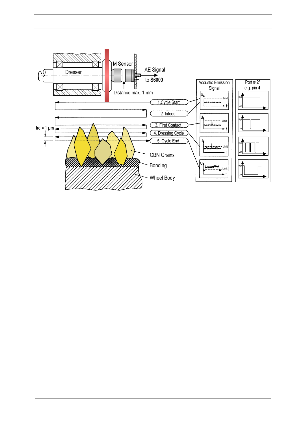
The S6000 in conjunction with the automation system is able to
recognise whether the dressing unit is in touch over the whole width
of the grinding wheel. If the dresser loses contact, the noise emission
decreases and a HIGH-signal is fed via pin 4 of connector #11 to the
automation system.
The HIGH- or LOW signal lasts at least 50 milliseconds to give the
automation system the possibility to recognise 'contact lost' or
'contact'. If there is any irregularity the automation system signals
another infeed of the dressing wheel or diamond till the contact, and
therefore the Acoustic Signal, is available over the whole width of the
grinding wheel.
2.2.4 Monitoring the Dressing Process
IWF-Technical University Braunschweig
Figure 2-2
May 2021 DITTEL – ODNFL61EN01 11 of 120
2 Introduction
S6000
The S6000 includes a Crash Control (collision monitoring) and
therefore an additional safety facility.
Should the detection of the very first contact of the grinding wheel and
the workpiece or dressing roller fail, the Crash Control reacts
instantaneously. A “Crash Limit exceeded” signal is given to the
automation system (via connector # 2 pin 10), which should initiate a
quick return and/or an emergency stop. Damage of the grinding
wheel, spindle and workpiece is therefore avoided.
First
contact
Tolerance of
workpiece radius
Safety Position
Workpiece
Rapid Infeed
Air Grinding Speed
Process Grinding Speed
Standard Infeed
CRASH!
2.2.5 Crash Control
Figure 2-3
12 of 120 DITTEL – ODNFL61EN01 May 2021
S6000
2 Introduction
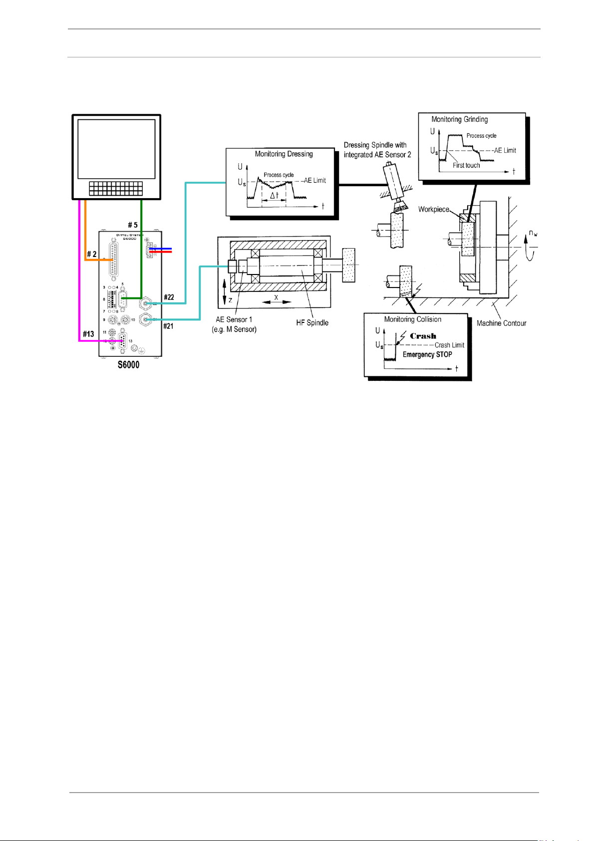
To monitor and evaluate an AE signal, caused by dressing or grinding
processes, the following components are required:
An AE Monitoring Module S6000,
An Automation System or a standard PC, based on Windows®,
and corresponding hardware.
A Dittel System Control Center (DSCC) Software,
Up to two AE sensors, active or passive, for example ‘S’, ‘M’, ‘Mini-
M’ or ‘R’ Type, customer designed ID sensors, AE sensors
integrated in the fixing flange of a balancing unit, etc.),
Connection and extension cables, as required.
CNC Machine Control
2.2.6 Example of Monitoring the Dressing and Grinding Process by means of two AE Sensors
IWF-Technical University Braunschweig
Figure 2-4
2.3 Components of an S6000 AE Monitoring System
May 2021 DITTEL – ODNFL61EN01 13 of 120
2 Introduction
S6000
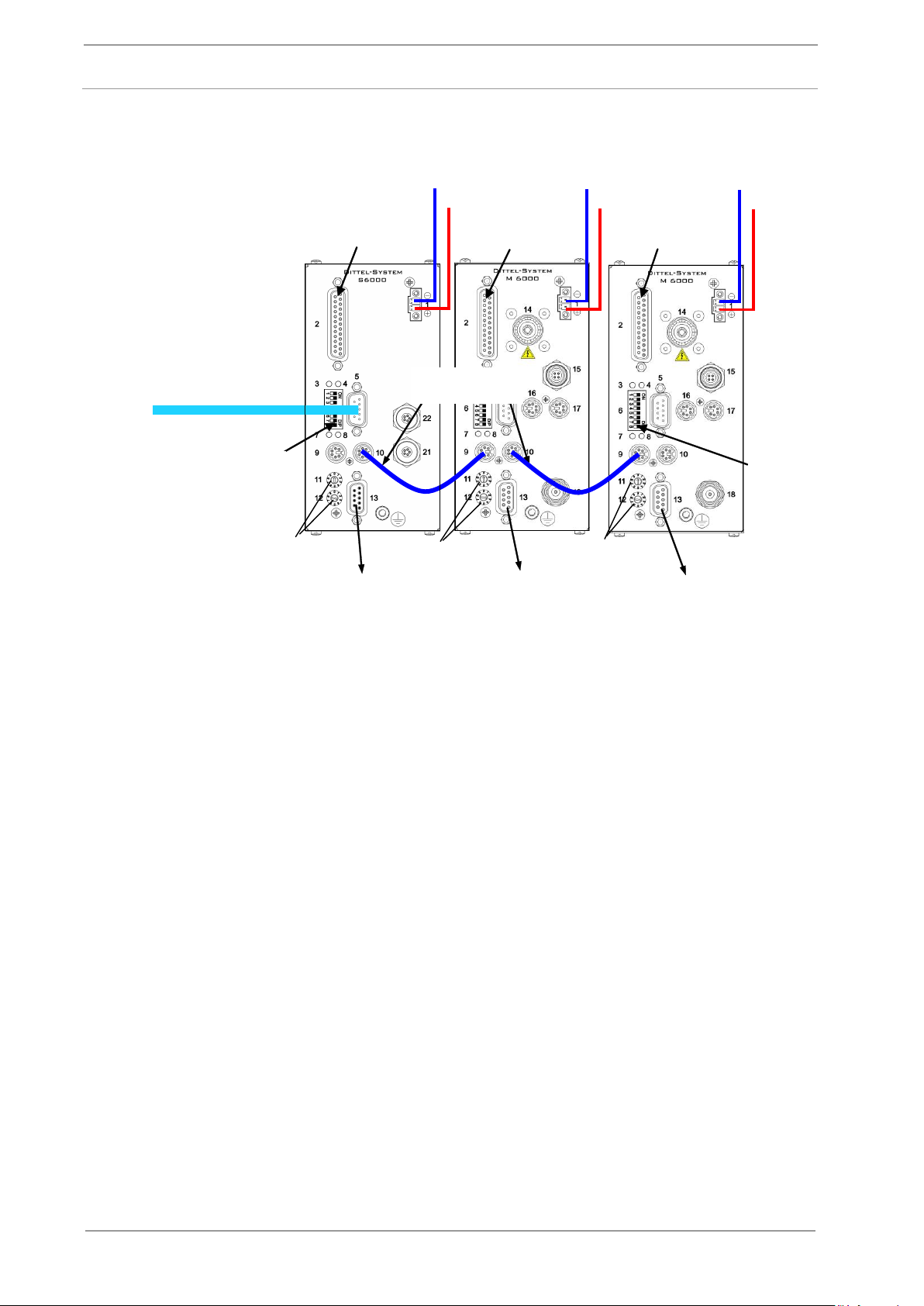
Adjust Address,
e.g. 03
Adjust Address,
e.g. 04
Adjust Address,
e.g. 05
Hardwire Interface
S6000
Hardwire Interface
M6000
Set Switch 8
to ON
Set Switch 8
to ON
Hardwire Interface
M6000
PROFIBUS
S6000
PROFIBUS
M6000
PROFIBUS
M6000
24 Vdc
24 Vdc
24 Vdc
RS-232 Interface Cable
to PC or Automation
System
Patch Cord
A/N O67L0020018
2.4 Connection of several DS6000 Modules to a S6000 Module
Figure 2-5
14 of 120 DITTEL – ODNFL61EN01 May 2021

S6000
2 Introduction
May 2021 DITTEL – ODNFL61EN01 15 of 120

3 Installation
S6000
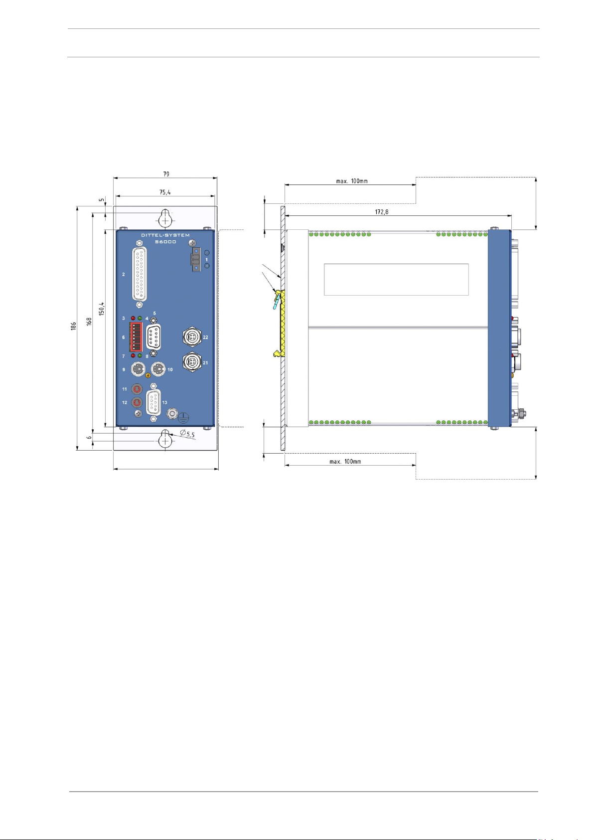
The ventilation holes of the S6000 should provide sufficient airflow.
Therefore do not cover the ventilation holes!
To allow adequate air circulation, place the next Module at least
20 mm (0.8”) / 50 mm (2”) away from the Module's top and
underside (see Figure 3-1, Dimensions).
The installation locality should fulfil the following conditions:
Environmental temperature 0 °C +50 °C / 32 °F … 122 °F,
Relative humidity 20% … 80%,
Altitude 0 2,000 m / 0 … 6,600 ft.,
No direct sunlight.
Atmosphere must be free of conductive substances, corrosive
gases, vapours, oily mist and dripping water. In addition, avoid
salty air as well as localities where condensation can appear by
temperature variation.
The Module S6000 is intended to be installed in control cubicles.
Mounting hardware is available for installation on vertical surfaces,
either a mounting panel (Mounting Set 6000-rear panel, article
number O10L0001001, formerly A/N E59420) or a clamping device
for DIN mounting rails (Mounting Set 6000-clamping device, article
number O20L0001001, formerly A/N E59474).
3 Installation
3.1 Mechanical Installation
3.1.1 Acoustic Emission (AE) Monitoring Module S6000
16 of 120 DITTEL – ODNFL61EN01 May 2021
S6000
3 Installation
Clearance
at least. 20 mm
Clearance
at least 20 mm
Clearance
at least 50 mm
Clearance
at least 50 mm
Optional
mounting
hardware
Distance at least 80 mm
Figure 3-1 S6000
Dimensions
May 2021 DITTEL – ODNFL61EN01 17 of 120
3 Installation
S6000
Contact MARPOSS S.p.A. or your nearest MARPOSS Agency for
application assistance!
Dimensions and illustration of our standard AE sensors are
available on request.
Risk of injuries by rotating parts!
Switch OFF the machine when installing or adjusting AE sensors!
Ensure that the machine spindle has stopped before working on it!
Protect the machine against unauthorised or accidental switching
ON!
NEVER operate a machine tool without all proper safety guarding
in place.
The location and installation of the AE sensor is crucial to
successful operation of the S6000 AE Monitoring!
NEVER mount the AE sensor on thin or loosely attached machine
parts like wheel guards. Take care to have only little numbers of
joints between the source of the signal (e.g. wheel or work piece)
and the sensor.
Ensure that suitable bonding straps bond all sensitive components
to a common local earth (ground).
The standard AE sensors can be mounted on the machine tool or
spindle either permanently stud mounted or kept by magnetic force
(type MGP 1).
The sensor location should be flat, smooth, and free of paint, and
must be free of foreign matter such as burrs or cuttings. Apply a thin
layer of silicone grease before mounting to achieve minimal loss of
the AE signal.
When choosing the position of the AE sensor(s) please be aware that
any blast of compressed air, or any heavy 'metal to metal contact',
may cause the S6000 to feed a "Crash" signal to the automation
system, which may initiate an "Emergency Stop".
3.1.2 Installation of AE sensors
General
18 of 120 DITTEL – ODNFL61EN01 May 2021
S6000
3 Installation
These AE sensors consist of one part and are connected directly to
the AE Monitoring Module. The AE signal is picked up via the base
plate.
The AE sensor with magnetic base plate MGP1 needs only a flat spot
with at least 40 mm diameter. The pull-off strength is approximately
60 N.
To fix the AE sensor ‘S’ a flat spot with at least 22 mm diameter and a
threaded M6 hole, depth at least 8 mm, is necessary.
To obtain a good "signal to noise ratio" the following locations are
recommended for both types of sensors:
Tailstock close to the work piece axis,
Work piece headstock near the spindle,
Grinding machine's headstock close to the wheel axis.
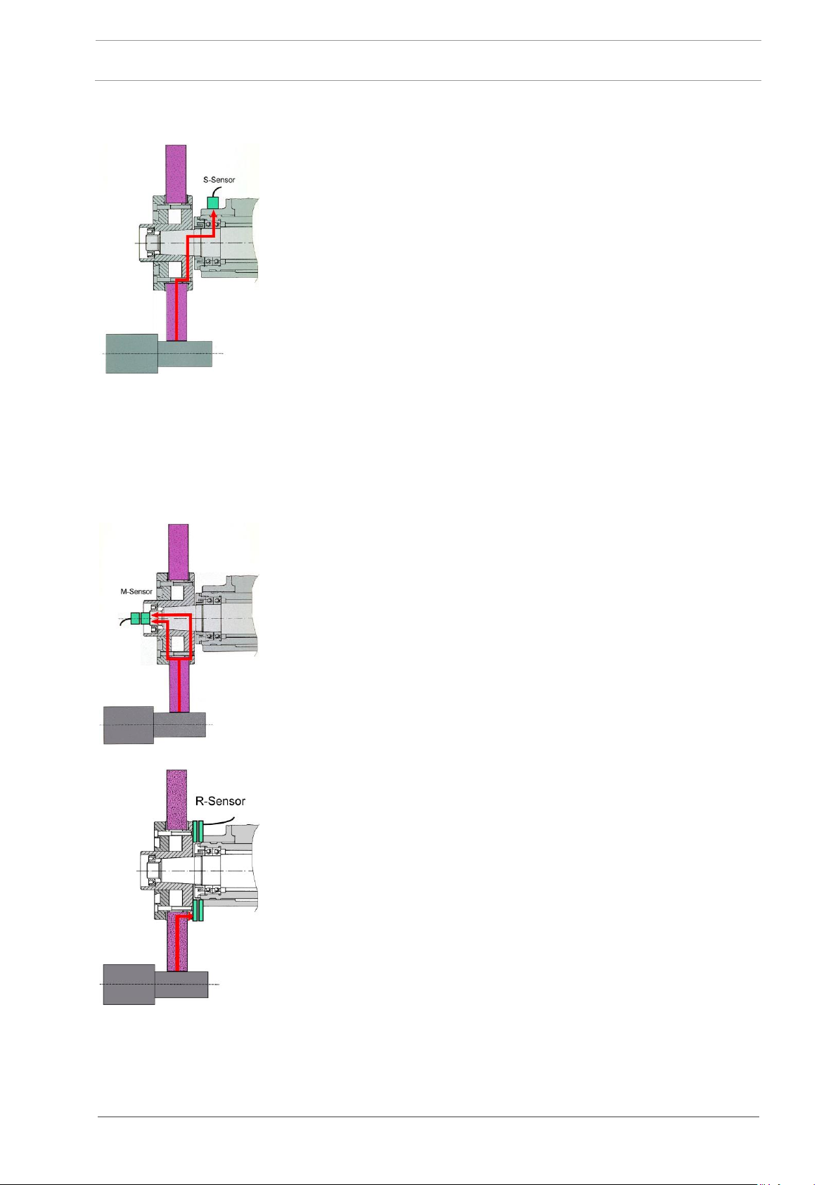
These sensors consist of two parts:
A rotating part, mounted on or in the spindle,
and a fixed part which receives the AE signal contact free from the
rotating sensor.
To fix the AE sensor "M" a threaded M6 hole, depth at least 8 mm, is
necessary. The appropriate sensor receiver must be fixed centrally
within a distance of 0.5 to 1.0 mm by means of two M3 screws (for
standard dimensions please contact our nearest representative).
Ring shaped AE sensors are manufactured according to customer's
specification. Therefore they differ in mounting and size (for minimum
dimensions please contact our nearest representative).
The following locations are recommended for both types of sensors:
Spindle or flange of dressing unit (esp. for monitoring of Touch
Dressing),
Grinding wheel spindle,
Work piece spindle.
AE sensor ‘S’ or Magnetic Type AE sensor ‘MGP1’
Centre Mounted AE sensor ‘M’ or AE Ring sensor ‘R’
May 2021 DITTEL – ODNFL61EN01 19 of 120
3 Installation
S6000
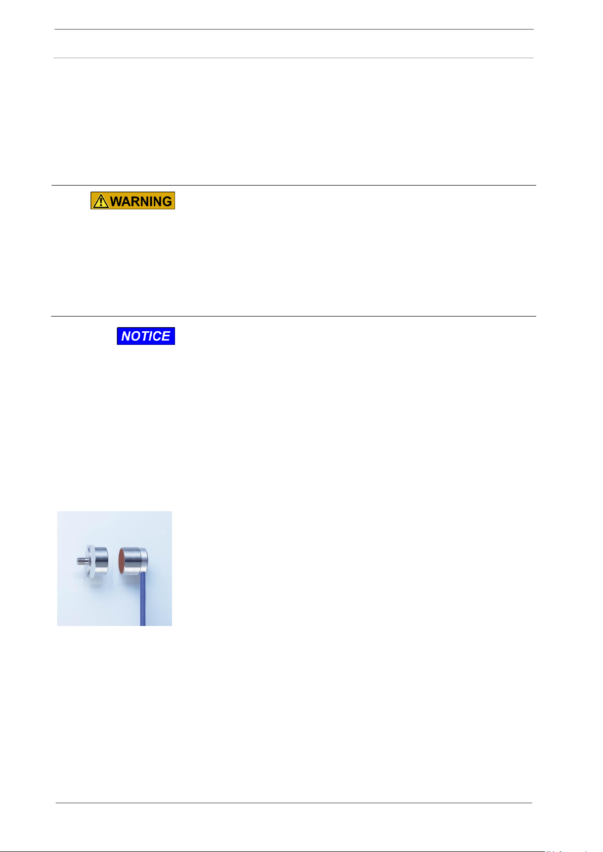
This AE sensor consists of one part and is connected electrically
direct to the AE Monitoring Module. The AE signal is picked up via the
coolant steam.
Attach the AE Fluid sensor so that its coolant stream hits directly
the monitored process.
Perfect results are obtained when coupling the measuring stream
to non-rotating surfaces (e.g. workpiece when surface grinded).
The mounting of custom-designed sensors is carried out according
local conditions.
Fluid-Sensor
Coolant
stream
AE Fluid sensor
Custom-designed AE sensors, e.g. ID sensors
20 of 120 DITTEL – ODNFL61EN01 May 2021
S6000
3 Installation
To ensure proper function of the S6000 Module(s) please use
only connection cables or extension cables supplied by Dittel
Messtechnik GmbH.
To reduce electrical interference make sure that the Module
S6000, all sensors and the machine CNC control are on a
common mass potential. If this is not guaranteed by the
installation on the machine, all components must be bonded by
suitable bonding straps to a common local earth (ground).
Secure all Standard DB Connectors by using the provided screw
locks.
Please safeguard cables with strain relief. Make sure that no
tensile stress is exerted on the connectors by the connected
cables.
Wiring the supply must be made by qualified staff of the customer!
Power the device from a 24 Vdc supply only! The power source
must comply with EN 60950 SELV (Safety Extra Low Voltage).
Applying a higher voltage can cause a damage of the device.
The S6000 module must be protected by an external fuse of
4 amps time-lag (T4A).
This fuse must comply with IEC 60127 and must blow within
120 sec or less at a current of 8.4 amps.
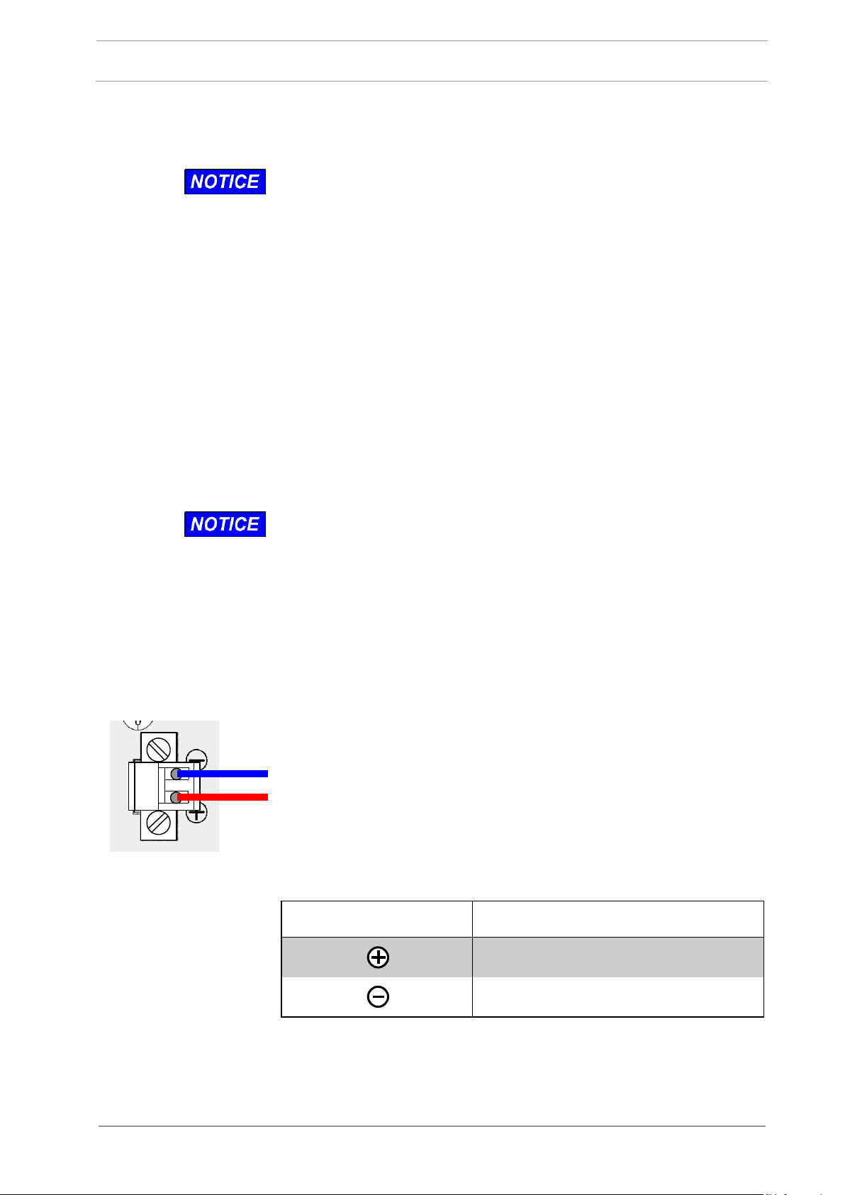
The supplied 2-pole DC plug with coded lugs fits the DC input of
the S6000. For wiring, use stranded wires, cross section 1.0 to
1.5 mm², and wire-end sleeves. Fix plug with both screws!
The S6000 is switched ON and OFF by the external power supply,
the Module itself contains no ON/OFF switch.
Lack of supply voltage does not result in loss of information in the
memory.
Contact
Signal
+ 24 Vdc ± 6 Vdc
Power Ground
3.2 Electrical Installation
3.2.1 General
3.2.2 Connector # 1, 24 Vdc Supply
May 2021 DITTEL – ODNFL61EN01 21 of 120
3 Installation
S6000
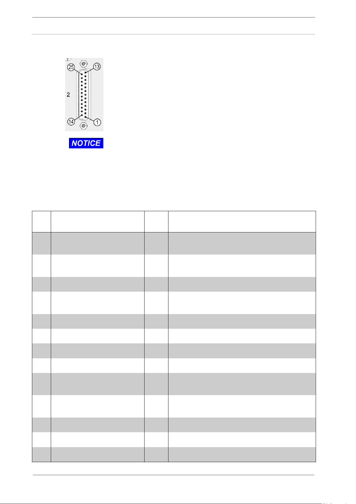
Type: Standard DB-25 Connector, female
Static interface of the AE Monitoring to the Automation System.
Via the inputs, the Automation System using HIGH or LOW signals
can control the AE Monitoring Module S6000.
Via the outputs, the Automation System receives various
messages from the S6000 as HIGH or LOW signals.
Wiring the interface mating plug # 2 (supplied) to the Automation
System must be made by qualified staff.
Use only shielded cable (shield connected to plug housing),
cross-section of the cable 0.25 sq mm (#24 AWG) minimum.
Cover the solder joints on the 25-pole mating plug with shrinking
tube.
Safeguard cables with strain relief.
Pin #
Function
Input/
Output
Signal / Action
1
Status
O
S6000 operating: HIGH at the output
S6000 not operating: LOW at the output
2
Monitoring AE/Crash sensor
O
Selected sensor OK: HIGH at the output
No sensor signal: LOW at the output
3
Reserved
X
Do not wire!
4
Monitoring AE Limit of
selected set
O
AE signal below Limit: HIGH at the output
AE signal above Limit: LOW at the output
5
Reserved
X
Do not wire!
6
Reserved
X
Do not wire!
7
Reserved
X
Do not wire!
8
Reserved
X
Do not wire!
9
CM
I
+24 Vdc supply, must fulfil EN 60950 SELV,
for example from the CNC Control
10
Monitoring Crash Limit of
selected set
O
Crash signal below Limit: HIGH at the output
Crash signal above Limit: LOW at the output
11
Reserved
X
Do not wire!
12
Reserved
X
Do not wire!
13
Reserved
X
Do not wire!
3.2.3 Connector # 2, Hardwire Interface of AE Monitoring
22 of 120 DITTEL – ODNFL61EN01 May 2021
S6000
3 Installation
Pin #
Function
Input/
Output
Signal / Action
14
Operation via keys or buttons
inhibit
I
Static HIGH Signal: Operator actions on the PC
or Automation System keyboard/softkeys are
disabled
15
Selects Set No.
I
Truth table, see below
16
Selects Set No.
I
Truth table, see below
17
Reserved
X
Do not wire!
18
Reserved
X
Do not wire!
19
Reserved
X
Do not wire!
20
Ground
X
Do not wire!
21
Reserved
X
Do not wire!
22
Reserved
X
Do not wire!
23
Reserved
X
Do not wire!
24
Reserved
X
Do not wire!
25
Reserved
X
Do not wire!
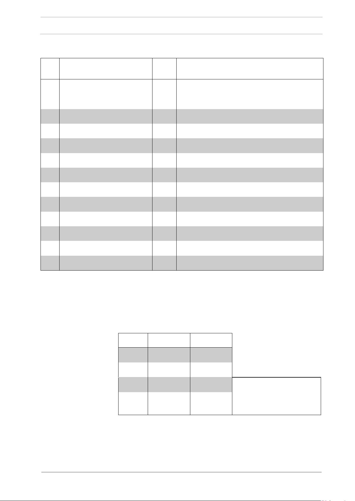
Set No.
# 11/pin 15
# 11/pin 16
1
HIGH
LOW
2
LOW
HIGH
LOW
LOW
Automation system signals
will not cause any change of
the actual Set Number
setting
HIGH
HIGH
Connector # 2, Hardwire Interface of AE Monitoring
X = not specified!
Connector # 2,
Truth table, to select appropriate Set no. by the machine CNC
control:
May 2021 DITTEL – ODNFL61EN01 23 of 120
3 Installation
S6000
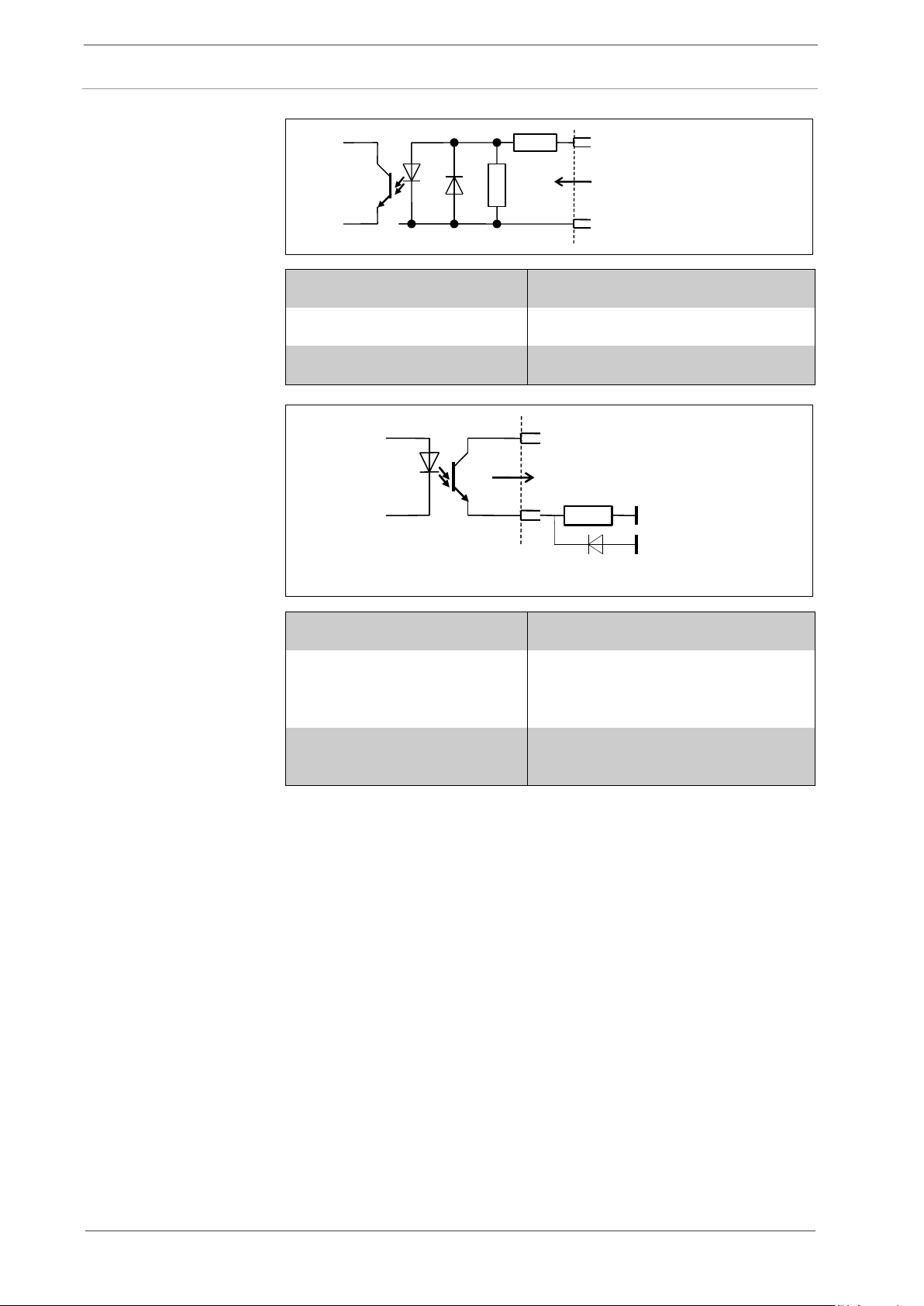
Connector # 2,
specification of digital
inputs, refer to pins 14,
15 and 16:
3K9
1
K
0
Input
20 Ground
From Machine
CNC Control
Digital
Inputs:
Input Signal LOW:
-30 Vdc … +3 Vdc
Input Signal HIGH:
+13 Vdc … +30 Vdc
Input Current:
typical 5.5 mA at 24 Vdc
Connector # 2,
specification of digital
outputs, refer to pins 1,
2, 4 and 10:
9 CM + 24 Vdc
Output
To machine CNC
Control
Digital
Outputs:
Load
Clamping Diode,
if required
Output Current:
10 mA
Recommended Load:
2.2 kΩ – 4.7 kΩ at 24 Vdc
Drive inductive load with clamping
diode only!
Power dissipation of
Switching Transistor:
75 mW maximum
24 of 120 DITTEL – ODNFL61EN01 May 2021
S6000
3 Installation
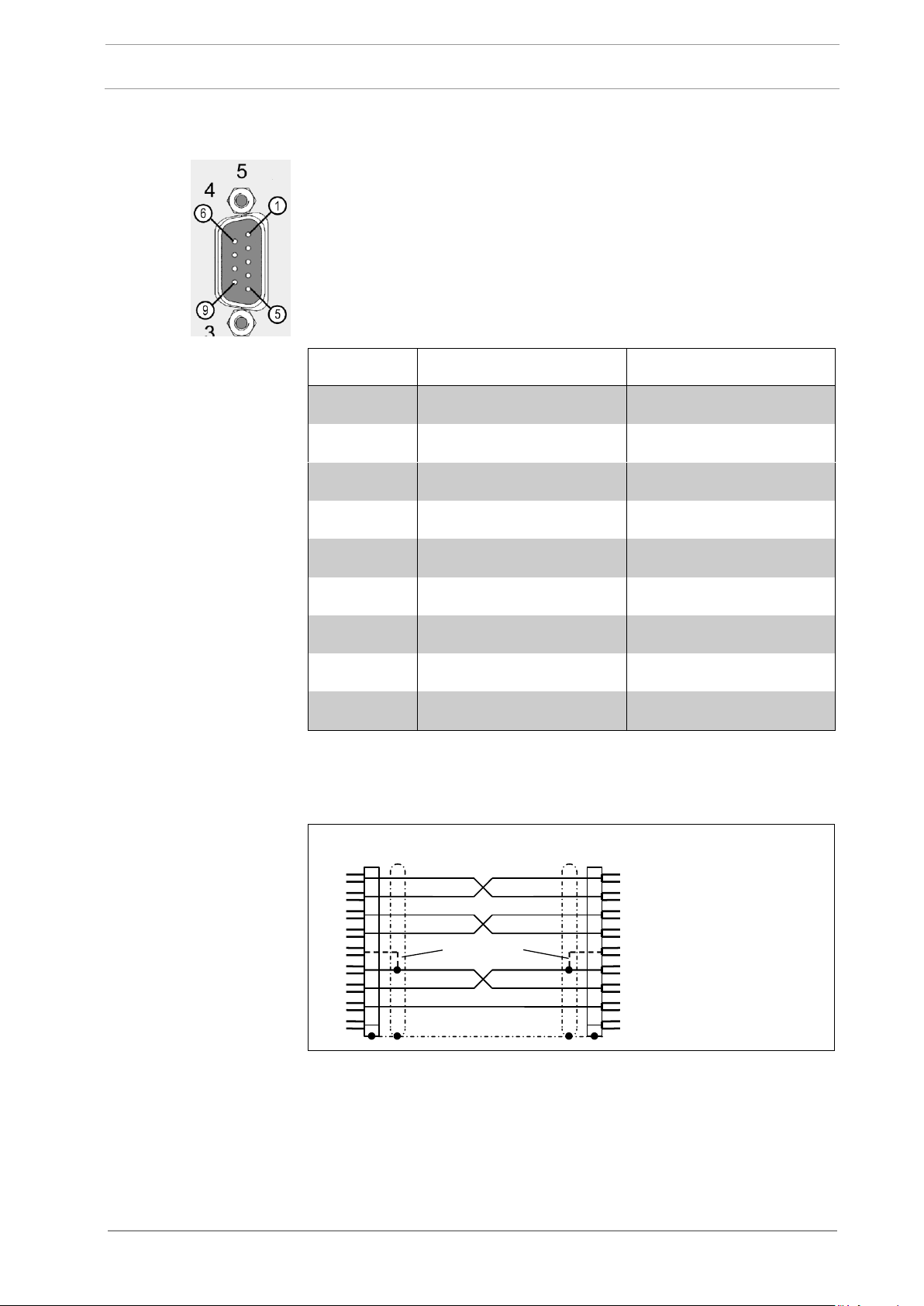
Type: Standard DB-9 Connector, male
RS-232-C Software Interface to operate the S6000 Module
through a computer based Automation System or a standard
Windows® Computer (Windows® XP/7/10) and additional Dittel
System Control Center Software.
Pin #
Input / Output
Signal
1 I DCD 2 I
RxD
3 O TxD
4 O DTR
5 - Signal GND
6 I DSR 7 O
RTS
8 I CTS
9 - not wired
Connect Module’s Connector # 5 by a shielded 9-pole Serial
Interface cable to an available serial port of your Automation
System or Computer.
Serial Interface Cable to
connect a computer or
Automation System
Not required
3 TxD
2 RxD
7 RTS
8 CTS
1 DCD
6 DSR
4 DTR
5 Signal GND
9 NOT WIRED
3
2
7
8
1
6
4
5
9
Standard DB-9, female
Screen
Standard DB-9, female
Serial Interface Cable
5 m A/N O67L0010500 10 m A/N O67L0011000
(A/N K0010500) (A/N K0011000)
15 m A/N O67L0011500 20 m A/N O67L0012000
(A/N K0011500) (A/N K0012000)
3.2.4 Connector # 5
May 2021 DITTEL – ODNFL61EN01 25 of 120
3 Installation
S6000
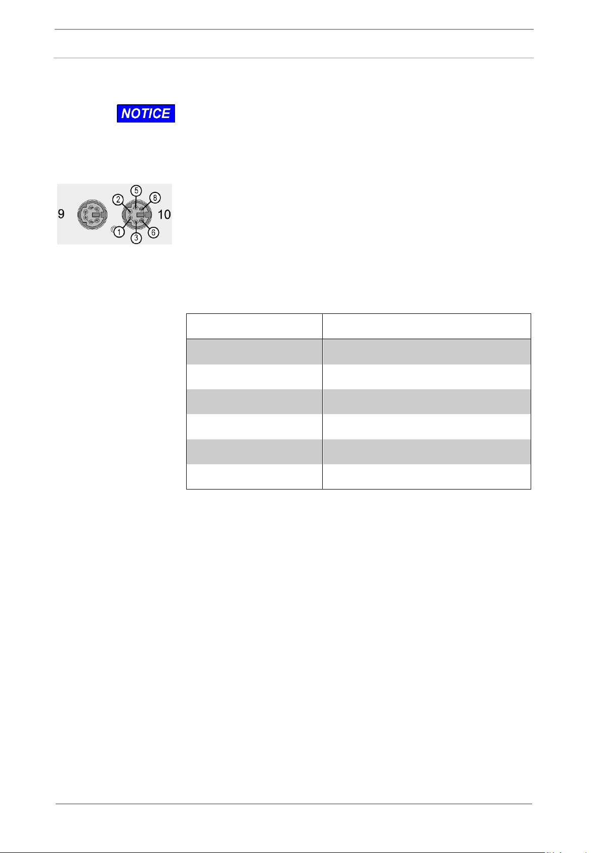
These sockets are used to connect up more than one DS6000
Module!
The first and last Module of the network has to be terminated
(refer to 3.3.1 Setting the DIP-Switch # 6, switch SW8 = ON).
Type: 6-pole Miniature DIN-Sockets
When operating more than one DS6000 Module they must be
connected up by special Patch Cords, length e.g. 18 cm/ 7” (A/N
O67L0020018, formerly A/N K0020018). At Modules placed side
by side, practically Connector # 9 is connected to Connector # 10
of the next Module and so on. However, connecting Connector # 9
to # 9 or Connector # 10 to # 10 is permitted as well.
Pin no.
Signal name
1
not connected
2
not connected
3
CAN-H
5
COMM GND
6
not connected
8
CAN-L
3.2.5 Connectors # 9 and # 10
26 of 120 DITTEL – ODNFL61EN01 May 2021
S6000
3 Installation
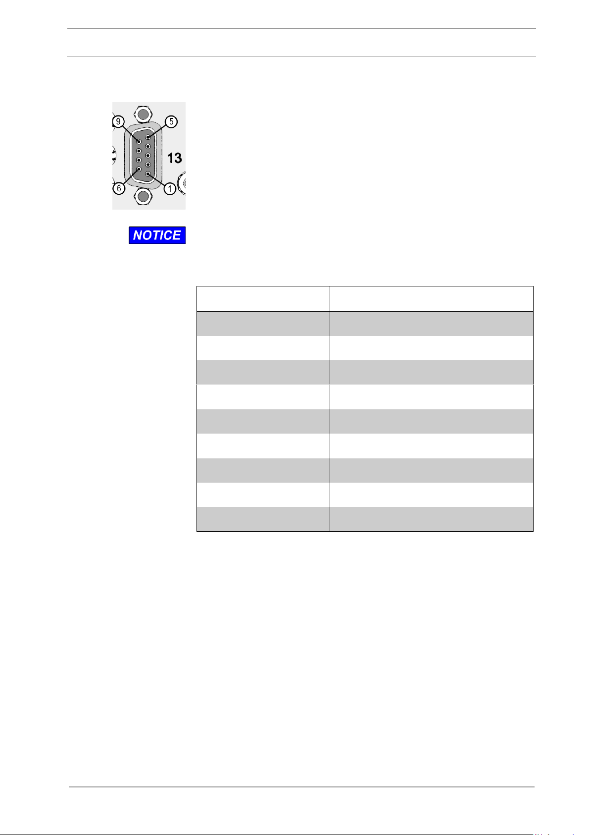
Type: Standard DB-9 Connector, female
Replaces among others all digital inputs and outputs of the
Hardwire Interface, Connector # 2.
Connection to a PROFIBUS Interface of an Automation System or
PC requires special PROFIBUS-cable and -plug.
Qualified staff of the customer must make the wiring of the
PROFIBUS Interface, Connector # 13, to the PC or Automation
System!
Pin no.
Signal name
1
not connected
2
not connected
3
RxD/TxD-P (Data line B)
4
CNTR-P
5
DGND (Data reference potential)
6
VP (Power supply plus)
7
not connected
8
RxD/TxD-N (Data line A)
9
not connected
3.2.6 Connector # 13, PROFIBUS Interface of AE Monitoring
May 2021 DITTEL – ODNFL61EN01 27 of 120
3 Installation
S6000
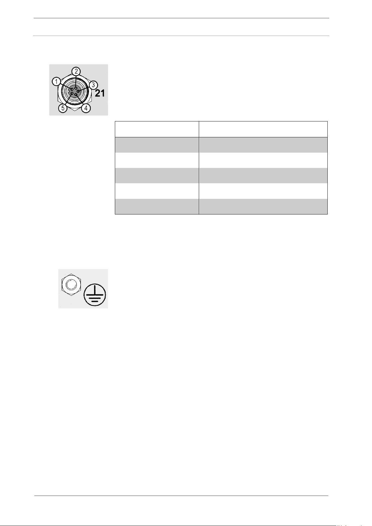
Type: 5-pole Miniature Sockets
To connect an AE sensor each.
Pin no.
Signal name
1
+ Supply of an Active Sensor
2
+ AE Sensor Signal
3
- AE Sensor Signal
4
RESERVED
5
- Supply of an Active Sensor
To reduce electrical interference make sure that the Module S6000,
all sensors and the machine CNC control are on a common mass
potential. If this is not guaranteed by the installation on the machine
all components must be bonded by suitable bonding straps to a
common local earth (ground).
Bonding of the S6000 is done via the ground terminal M4. Use a
bonding strap with ring-type cable lug.
The bonding straps should be as short as possible, the cross
section as big as possible.
3.2.7 Connectors # 21 and # 22
3.2.8 Ground terminal, stud M4 and hex nut
28 of 120 DITTEL – ODNFL61EN01 May 2021
S6000
3 Installation
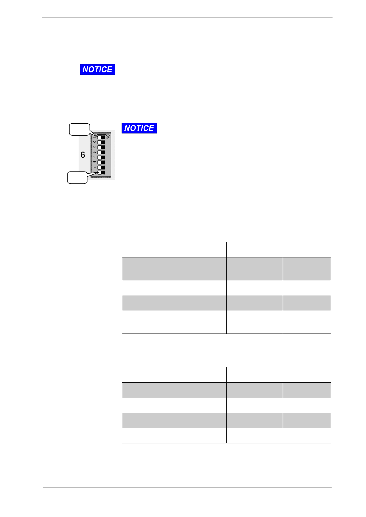
Every change of the switches # 6, # 11, and # 12 (except SW8 of
DIP-Switch # 6) gets effective only after switching OFF and ON again
the supply voltage of the Module!
SW1
SW8
Before getting started the S6000, some settings must
be carried out with the eight switches, if applicable!
Setting the RS-232
Baud Rate:
The Baud Rate to be adjusted here must agree with the RS-232
interface of your PC or Automation System (always 57600) or agree
with the external interface converter (serial/Ethernet).
SW1
SW2
Standard Setting: 57,600,
1 Stop bit, no Parity:
OFF
OFF
38,400, 1 Stop bit, no Parity:
ON
OFF
19,200, 1 Stop bit, no Parity:
OFF
ON
programmable from PC
(Default Setting: 208,333)
ON
ON
Setting the CAN Baud
Rate:
Required if more than one Module is used!
SW3
SW4 Default Setting: 500k:
OFF
OFF
250k:
ON
OFF
125k:
OFF
ON
1M:
ON
ON
3.3 Settings before getting started
3.3.1 Setting the DIP-Switch # 6
May 2021 DITTEL – ODNFL61EN01 29 of 120
3 Installation
S6000
SW5
SW6
Default setting NORMAL:
OFF
OFF
For future use:
ON
OFF
Reset to Factory Setting (for
authorised personnel only):
OFF
ON
For future use:
ON
ON
Bootstrap Loader
Mode:
For authorised personnel only!
SW7:
Standard: OFF
CAN Terminator:
The first and last Module of a module network must be terminated, i.e. switch SW8 of these Modules must be set to ON!
SW8:
ON / OFF
Default Setting: OFF
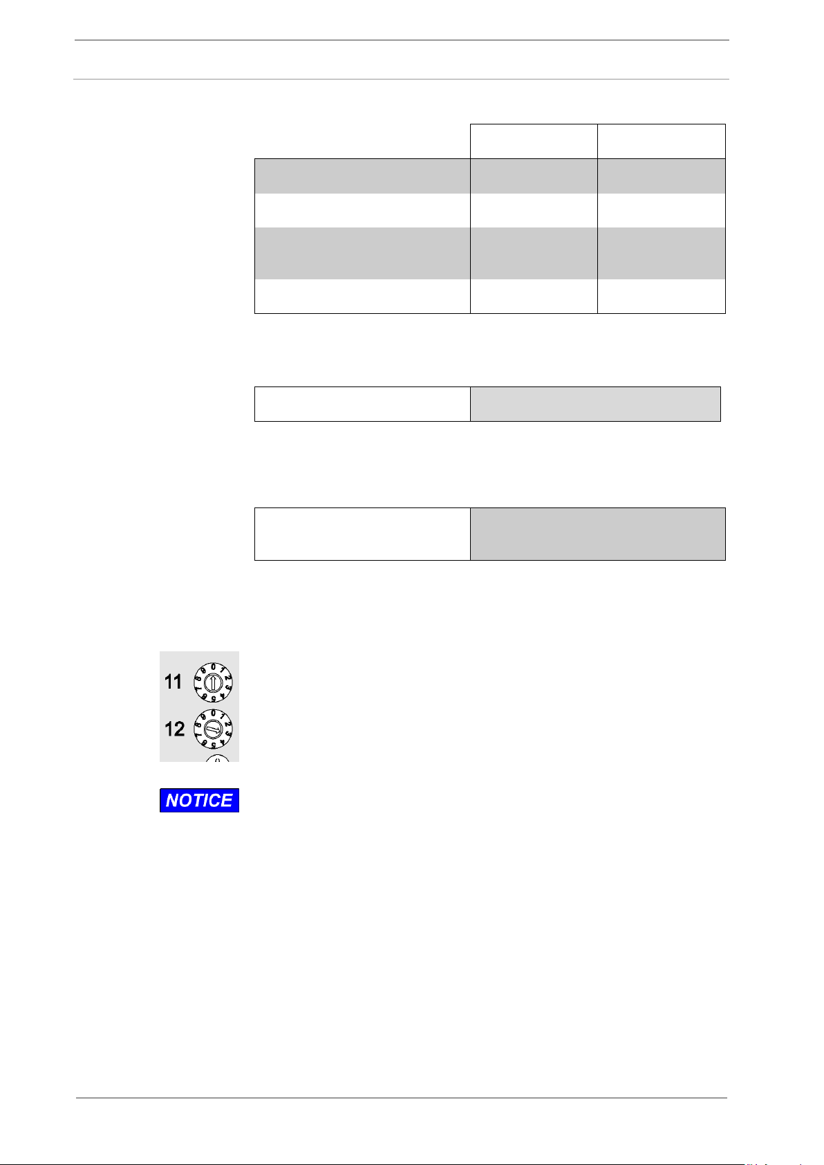
Factory setting: Module Address ‘03’!
By using the rotary decode switches # 11 (tens) and # 12 (units) the
Module Address (03 … 99) is set.
At several Modules set on every Module another Module Address
except ‘00’!
When setting the Module Address ‘00’, the LEDs #3 and #7 are
flashing slowly and alternately; the Module S6000 is not
operational!
The Module Address complies with the PROFIBUS address. When
operating the S6000 Module via PROFIBUS Interface notice
addresses of other PROFIBUS user.
Every change of the Module Address gets effective only after
switching OFF and ON again the supply voltage of the Module!
Operation Mode:
3.3.2 Rotary Decode Switches # 11 and # 12
30 of 120 DITTEL – ODNFL61EN01 May 2021
 Loading...