

Dittel FSG 90 PC Operator's Manual
FCC ID:
BVYFSG90
FAA: TSO C37d
TSO C38d
No. LBA.O.10.911/98 JTSO
replaced by:
ETSO: EASA.21O.1305
DFS-No.: B-7850/97
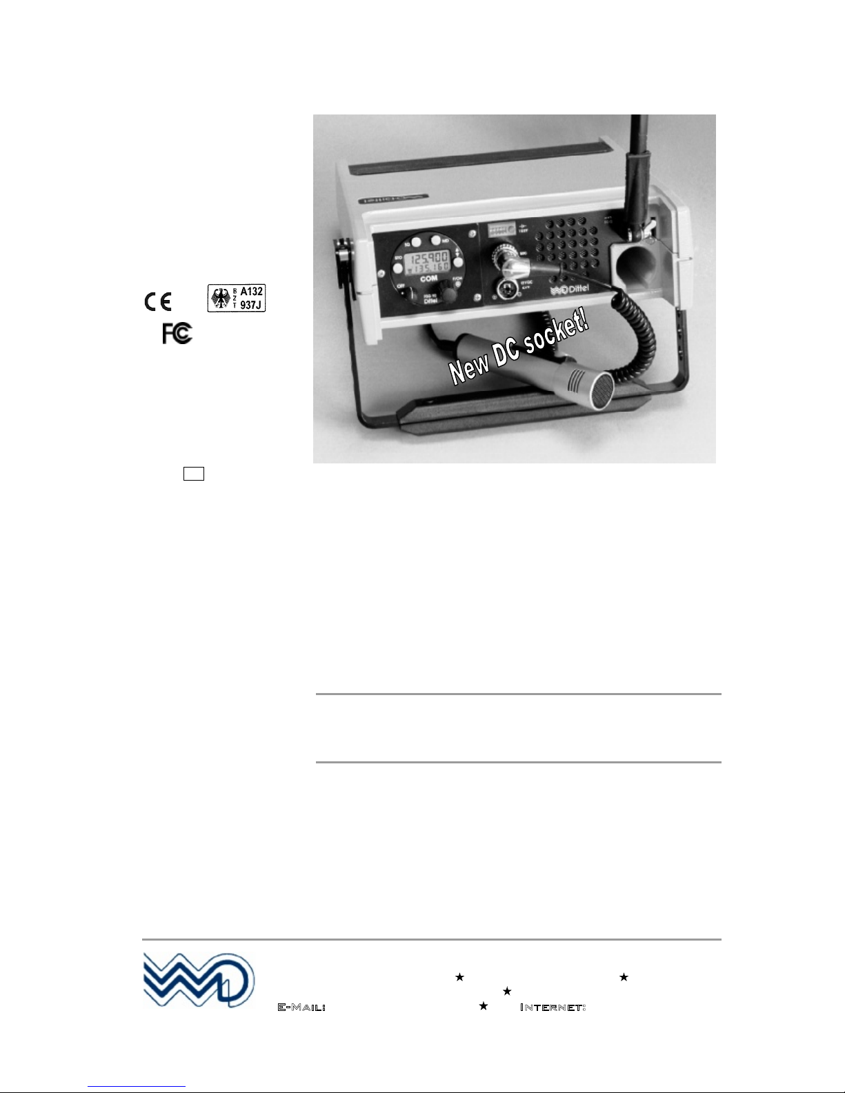
FSG 90 PC
Dual Mode VHF/AM
FIXED/PORTABLE/MOBILE
AIRBAND TRANSCEIVER
OPERATOR'S MANUAL
Before operating the Transceiver, please read
this manual thoroughly!
Please observe the Safety Information!
Keep for further use!
Date of Issue May 2010
Document no.: BA 154.90-EN Article no. D10075
Dittel Messtechnik GmbH
Avionics Division
Erpftinger Straße 36 86899 Landsberg Germany
Telephone +49 (0)8191/ 3351-0 Fax +49 (0)8191/ 3351-49
E-Mail: info@dittel.com Internet: www.dittel.com
Dittel Messtechnik GmbH is certified to DIN EN ISO 9001:2000 and DIN EN ISO 14001:2005. It is an accredited manufacturer of aeronautical equipment
DE.21G.0100, maintenance facility DE.145.0245, and development facility ETSO-2C37e/ETSO-2C38e.
e1
03 5042
KBA:

PORTABLE TRANSCEIVER FSG 90PC
Operator's Manual
2
DITTEL D10075 May 2010
Copyright - Service
Copyright 2010
Dittel Messtechnik GmbH
All rights reserved. This document contains proprietary information and such
information may not be disclosed to others for any purpose nor used for
manufacturing purposes without prior written permission of the manufacturer
Dittel Messtechnik GmbH, 86899 Landsberg am Lech, Germany.
In this document no mention is made of patents, trademark rights, or other
proprietary rights which may attach to certain words or entries. The absence
of such mention, however, in no way implies that the words or entries in
question are exempt from such rights.
Service Information
Should any unusual problem arise or further information be desired, please
contact your nearest DITTEL representative or the Dittel Messtechnik
GmbH, Avionics Division, Erpftinger Strasse 36, 86899 Landsberg,
Germany.
The information in this Operator's Manual does not profess to include all the details of
design, production, or variation of the equipment, or to cover all the possible
contingencies which may arise during operation or maintenance. We welcome your
comments concerning this Manual. Although every effort has been made to keep it
free of errors, some may occur. When reporting a specific problem, please describe it
briefly and include the Operator's Manual article number, paragraph or figure
number, and the page number.
Send your comments to Publications Department
Dittel Messtechnik GmbH
Erpftinger Strasse 36
86899 Landsberg am Lech
Germany
or via e-mail to: info@dittel.com
Subject to technical changes Printed in Germany

PORTABLE TRANSCEIVER FSG 90PC
Safety Information
May 2010
DITTEL D10075
3
Safety Information
Every radio, when transmitting, radiates energy into the atmosphere
that may, under certain conditions, cause the generation of sparks. All
users of our radios should be aware of the following warning:
Do not operate this radio in an explosive atmosphere (petroleum
fuels, solvents, dust, etc.)!
During normal use, the radio will subject you to radio energy
substantially below the level where any kind of harm is reported.
TO ENSURE
PERSONAL SAFETY
Please observe the following simple rules:
Only persons entitled may operate the
FSG 90 PC
!
DO NOT lean over the equipment when opening the cover! If not
properly tightened the spring steel band antenna may bounce out!
DO NOT transmit when the antenna is very close to, or touching,
exposed parts of the body, especially the face and eyes.
DO NOT transmit on a busy channel!
DO NOT transmit in closed vehicles, aircraft or inside buildings
with the spring steel band antenna! This may cause malfunction of
the avionics, trigger the airbag or confuse electronic equipment!
Always operate the radio with a suitable external antenna! Assure
appropriate lightning protection where elevated outdoor antennas
are used.
DO NOT
press the transmit (PTT) key when not actually desiring
to transmit.
DO NOT allow children to play with any radio equipment
containing a transmitter.
DO NOT operate the radio whilst driving. It should also be noticed
that the use of a hand held microphone while driving could
constitute an offence under the Road Traffic Regulations in certain
countries.
DO NOT dispose worn out lead batteries with the household
garbage.
Always switch OFF the radio when plugging or unplugging the
receptacle!
Always switch OFF the radio first when starting an engine or
vehicle!
The FSG 90 PC may be used exclusively for communication on the
airband frequencies.
Unauthorized modifications and changes of the system are
forbidden.
When replacing defective parts use only original spare parts or
standard parts recommended by the manufacturer!
PORTABLE TRANSCEIVER FSG 90PC
Safety Information
4
DITTEL D10075 May 2010
Used Symbols
In this manual the following symbols are used:
DANGER!
describes an immediate threatening danger! Failing to observe the
note may cause death or heaviest injuries.
WARNING!
This warning note describes a dangerous high voltage. Failing to
observe the note may cause death or severe injury!
CAUTION!
describes a special note for operation. Failing to observe the note
may cause damage of the transceiver and/or stored data may be
deleted!
IMPORTANT!
describes explanations and other useful hints. Failing to observe
the note may cause degraded performance and/or unsatisfying
operation!
Environmental Protection
After the implementation of the European Directive 2002/96/EU in the
national legal system, the following applies:
Electrical and electronic devices may not be disposed of with
domestic waste. Consumers are obliged by law to return electrical
and electronic devices at the end of their service lives to the public
collecting points set up for this purpose or point of sale. Details to this
are defined by the national law of the respective country. This symbol
on the product, the instruction manual or the package indicates that a
product is subject to these regulations. By recycling, reusing the
materials or other forms of utilizing old devices, you are making an
important contribution to protecting our environment.
Pb
The portable airband transceiver FSG 90 PC
contains a sealed
lead-acid battery (identification "Pb").
In most countries it is illegal to discard a lead-acid battery except
by delivery to a retailer, a distributor, a manufacturer, or a
collection, recycling, or smelting facility approved by the
department.
NEVER dispose worn out lead-acid batteries with the household
garbage.

PORTABLE TRANSCEIVER FSG 90PC
Table of Contents
May 2010
DITTEL D10075
5
Table of Contents
Copyright - Service................................................................2
Safety Information .................................................................3
Table of Contents ..................................................................5
1 General Description ............................................................7
1.1 Introduction.................................................................................................7
1.2 Application & Description of the FSG 90 PC...............................................7
1.3 Scope of Delivery.......................................................................................8
1.4 Operating License......................................................................................7
1.5 System and Type Approval Information.....................................................8
1.6 Optional Accessories................................................................................10
2 Functional Description......................................................11
2.1 Introduction...............................................................................................11
2.2 Operator's Controls and Indicators...........................................................11
3 Set-up Procedure...............................................................19
3.1 Calling SET-UP without password...........................................................20
3.2 Calling SET-UP with password................................................................20
3.3 Interrupt the SET-UP procedure ..............................................................21
3.4 SET-UP procedure...................................................................................21
3.4.1 Adjusting the automatic squelch threshold ............................................. 22
3.4.2 Adjusting the microphone sensitivity....................................................... 22
3.4.3 Adjusting the Intercom volume................................................................ 23
3.4.4 Adjusting the Sidetone volume................................................................ 23
3.4.5 Adjusting the headset volume (receive).................................................. 24
3.4.6 Selecting '25 kHz only' or combined 8.33/25 kHz channel spacing........ 24
3.4.7 Deleting occupied channel memories..................................................... 25
3.4.8 Selecting AF EXTERNAL (ON/OFF)....................................................... 25
3.4.9 Selecting 'CHANNEL MODE ONLY' or 'NO RESTRICTION'.................. 26
3.4.10 Selecting 'TX disabled' during receive (ON/OFF) ................................... 26
3.4.11 Service (ON/OFF) ...................................................................................27
3.4.12 Optional module (ON/OFF)..................................................................... 27
3.4.13 Entering a password................................................................................ 27
3.4.14 Reset....................................................................................................... 28
4 Operation............................................................................29
4.1 Introduction...............................................................................................29
4.2 Battery Check...........................................................................................29
4.3 Battery Charging ......................................................................................30
4.4 Antenna - Antenna Jack SO 239..............................................................31
4.5 Microphone...............................................................................................31
4.6 Switching ON - Selecting Frequency/Channel Name - Volume...............32
4.7 Receive (Listen) Operation ......................................................................34
4.8 Transmit (Talk) Operation ........................................................................34
4.9 Storing a new Frequency/Channel Name................................................36
4.10 Recall of stored frequencies/channel names:..........................................36

PORTABLE TRANSCEIVER FSG 90PC
Table of Contents
6
DITTEL D10075 May 2010
Table of Contents
4.11 Lighting the Frequency Display...............................................................37
4.12 Turning OFF the radio.............................................................................37
4.13 External Power Supply............................................................................37
4.14 Removing & Installing the Transceiver....................................................37
4.15 Battery Operating Times ......................................................................... 38
4.16 Siting........................................................................................................38
4.17 Base Operation........................................................................................38
4.18 Functional Checks................................................................................... 39
5 ICAO Frequency / Channel Name Assignment in the
combined 8.33 kHz / 25 kHz Operation ........................... 40
6 Technical Summary FSG 90 PC........................................ 41
6.1 General.................................................................................................... 41
6.2 Approvals.................................................................................................42
6.3 Detailed Receiver Characteristics...........................................................42
6.4 Detailed Transmitter Characteristics.......................................................44
6.5 Environmental Performance Classification .............................................45
Certificates ........................................................................ 49

PORTABLE TRANSCEIVER FSG 90PC
1 General Description
May 2010
DITTEL D10075
7
Section 1 General Description
1.1 Introduction
This operator's manual contains operating instructions for the fixed/
portable/ mobile VHF/AM Airband Transceiver FSG 90 PC of
Dittel Messtechnik GmbH, 86899 Landsberg am Lech, Germany.
1.2 Application & Description of the FSG 90 PC
The portable VHF/AM Airband Transceiver FSG 90 PC allows
independent operation as an airborne or ground radio. Stationary,
portable or mobile applications are possible. It consists of a portable
case PC 90 and a Dual Mode VHF/AM COM Transceiver FSG 90 or
FSG 90-H1, which can be simply inserted and positioned.
This radio is working within the airband frequency range of 118.000
MHz to 136.975 MHz in either combined 8.33 kHz/25 kHz increments
(2,278 channels) or '25 kHz only' increments (760 channels). The
operating mode is Simplex, i.e. transmitting or receiving only in turns
(two way communication). The RF output power of the radio FSG 90
is 6 Watt into 50 Ohms at 13.8 Vdc, the FSG 90-H1 is transmitting
with 10 Watt into 50 Ohms at a power supply of 14.0 Vdc.
The built-in rechargeable battery allows an independent operation of
up to 85 hours (refer to paragraph 4.15, Battery Operating Times).
Continuous operation is possible by the built-in charging unit or,
externally, from a vehicle or aircraft DC supply. Microphone and
antenna are retractable. External antennas, too, can be
advantageously used.
The unit features 99 non-volatile channel memories each in combined
8.33/25 kHz and in '25 kHz only' operation, 3 display modes, true
Sidetone via headphone, TX and supply voltage indicator at the backlit display, TX time-out timer (2 minutes), a battery supply test, and a
built-in loudspeaker. The lock-in type carrying handle and a protecting
hood completes our PC 90 unit.

PORTABLE TRANSCEIVER FSG 90PC
1 General Description
8
DITTEL D10075 May 2010
1.3 Scope of Delivery
A complete Portable VHF/AM Airband Base Station FSG 90 PC
consists of:
A portable case PC 90 (A/N F10387), containing 12 Vdc/7.2 Ah
lead calcium battery, charger for 115 Vac/230 Vac, 50 - 60 Hz, DC
supply indicator, DC supply socket, microphone socket, antenna
socket, loudspeaker, Snap-On cover - fits on top or bottom, and a
Operator's Manual.
a Dual Mode VHF/AM COM Transceiver FSG 90 or FSG 90-H1.
a suitable, vertically polarized VHF airband antenna, frequency
range minimum 118 to 137 MHz, 50 Ohm, e.g., spring steel band
antenna A/N F10345, and
a microphone, e.g., hand-hold dynamic microphone with PTT-
switch A/N F10041.
When operating on 24 Vdc sources a suitable 24 Vdc/12 Vdc
Converter of at least 4 Amps must be used!
1.4 Operating License
IMPORTANT!
Ground operation always requires an individual
operating license. Depending on national regulations,
such license must be applied for at appropriate National
Authorities, using suitable application forms.
1.5 System and Type Approval Information
The Dual Mode VHF/AM Airband Transceiver
FSG 90(X) complies for
both the 8.33 kHz/25 kHz as well as 25 kHz channel spacing with all
applicable National and International Type Approval requirements, for
any airborne and ground operation.
JTSO Authorization No. LBA.O.10.911/98 JTSO (LBA Luftfahrt-
Bundesamt) based on *EUROCAE ED-23B Airborne requirement
is met besides 8.33 kHz requirements also for the 25 kHz ONLY
channel spacing. This JTSO Authorisation was replaced by ETSO
Authorization EASA.21O.1305 in July 2009.
This also includes Immunity according to ICAO ANNEX 10 against
FM Broadcast Interference.
This also includes fulfillment of specific audio filtering required in
areas with CLIMAX operation in 25 kHz channel spacing.
* Associated EUROCAE ED-14C / RTCA DO-160C Environmental
requirements.
* Associated EUROCAE ED-12B Software requirements based on
ED-23B.

PORTABLE TRANSCEIVER FSG 90PC
1 General Description
May 2010
DITTEL D10075
9
Reg TP No. A132937J, stringent German Type Approval
requirements Reg TP 321 ZV 034 (airborne) and Reg TP 321 ZV
039 (ground).
DFS (Deutsche Flugsicherung) No. B-7850/97 (ground) German
Type Approval requirements.
BZT No. B132705J, CE Conformity,
* Associated with DIN/ISO 7637-1 DC supply in 12 V vehicle.
FCC Compliance with Part 15 (receiver) and Part 87 (transmitter).
EC-Type-Approval of a type of component with regard to Directive
72/245/EEC, as last amended by Directive 2006/28/EG.
IMPORTANT!
For the first time after one year, then every 2nd year, ground
applications using 8.33 kHz channel spacing require checking
of the high precision reference frequency (tolerance less than
± 1.5 ppm) and recalibration, if necessary!
Every 4th year, airborne applications using 8.33 kHz channel
spacing require checking of the high precision reference
frequency (tolerance less than ± 5 ppm) and recalibration, if
necessary!
All applications in the 25 kHz channel spacing require no
recalibration (frequency accuracy tolerance less than ± 20
ppm).
All tolerances include the full operating temperature range of
-20°C ... +55°C / -4°F ... +131°F.
Checking and recalibration must be performed by the
equipment manufacturer or through authorized and approved
avionics services. This requires use of specified test
equipment as well as applicable test procedures (software)
released by the manufacturer.

PORTABLE TRANSCEIVER FSG 90PC
1 General Description
10
DITTEL D10075 May 2010
1.6 Optional Accessories
Article-No. Description
F10345 Spring steel band antenna, swivel type, PL-259 connector
W00043 Magnet mount vehicle rod antenna, incl. 4 m/13 ft cable, and UHF
connector PL-259
W00066 Mobile Whip Antenna with shock spring, 118 - 137 MHz, incl. 5 m/
16.5 ft cable, w/out UHF connector PL-259
F10314 Balloon antenna, 118-137 MHz, weatherproof - flexible - high
efficiency, including 3 m/10 ft cable and UHF connector PL-259
W00013 Roof mounted weatherproof folded-top fiberglass antenna, UHF-
connector, anti static, 1" mount
E57328 UHF antenna connector PL-259 for antenna cable RG-213/U
B01116 Antenna cable RG-213/U, low loss, for roof antenna W00013,
please state length (in meters)
F10041 Dyn. hand-held microphone incl. PTT-switch, coiled cord and
5-pole plug
F10042 Dyn. hand-microphone/loudspeaker with PTT-switch, coiled cord
and 5-pole plug
F10125 Inline PTT-switch (U-94 A/U), coiled cord, 5-pole plug, to connect
headset W00048, clip allows attaching to clothing
W00048 Dynamic headset with PJ-plug, fits inline PTT-switch
F10393 Car Cable, coiled cord, incl. 3-pole plug to supply station from
12 Vdc car battery (fits cigarette lighter socket, minus = ground)
S20000 Converter 24 Vdc to 12 Vdc, 4 Amps, to operate the base Station
from 24 Vdc sources like truck batteries etc.
E61933 3-pole twist-lock DIN Connector, to fit into "12 V DC EXT." socket of
carrying case PC 90.
E08834 5-pole twist-lock DIN Connector, to fit into "MIC" socket of carrying
case PC 90.
E58411 Sealed lead accumulator, nominal 7.2 Ah, 12 VDC

PORTABLE TRANSCEIVER FSG 90PC
2 Functional Description
May 2010
DITTEL D10075
11
Section 2 Functional Description
2.1 Introduction
This section includes a functional description of each switch, push
button, knob, socket, indicator and display located on the front or rear
panel of the FSG 90 PC, together with operating instructions.
After removing the Snap-On cover all controls to operate the
transceiver are accessible. The cover can be pushed onto the rear
side of the carrying case.
DANGER!
DO NOT lean over the equipment when opening the cover! If
not properly tightened the spring steel band antenna may
bounce out!
2.2 Operator's Controls and Indicators
A front and back view of the FSG 90 PC is given on the last page of
this manual. Please fold out the back flap when reading the operating
instructions. Each position number of a control, knob, switch, etc.,
corresponds to the number of control, knob, switch, etc., given below.
1
ON/OFF-VOL Rotary step switch
To turn ON the radio rotate the ON/OFF-VOL knob clockwise from the
OFF position (dot).
When power is activated
all segments of the display are momentarily visible,
he automatic squelch is activated
the display shows the frequency/ channel name in that operating
mode, which was used before last turning OFF.
Rotating the ON/OFF-VOL knob clockwise increases - turning counterclockwise decreases the audio volume audible in the built-in
loudspeaker (Receive only) or connected headphone (TX Sidetone
and Receive).
To turn OFF the radio rotate the ON/OFF-VOL knob fully counterclockwise (ccw) to the OFF position (dot). Blank display.
2
STO
Push button
With the VHF/AM COM Transceiver FSG 90(X), up to 99
frequencies/channel names in each operating mode (combined
8.33/25 kHz mode or '25 kHz only' mode) may be stored in a nonvolatile memory. The channel memory numbers (1 99) are user
programmable.
PORTABLE TRANSCEIVER FSG 90PC
2 Functional Description
12
DITTEL D10075 May 2010
2
STO
continued
Programming a frequency:
1. Set the frequency or channel name to be stored in the upper line
at the display!
2. Initialize storing by pressing the STO button.
3. The last used channel memory number is displayed in the lower
line.
4. A flashing "CH" shows "ready to store".
5. Select appropriate (new) channel memory number (1 to 99) by
rotating the F/CH knob.
6. On a free channel memory an additional "F" (free) is displayed.
7. To enter the new frequency/channel name press the STO-button.
The frequency/channel name will be stored under the adjusted
channel memory number.
8. A previously stored frequency/ channel name will be overwritten.
9. The last used display mode is displayed.
Programming in the SET-UP mode:
In the SET-UP mode all settings must individually be confirmed by
pressing the STO button. Otherwise the settings are not permanently
stored.
3
SQ (SQUELCH) Push button
After turning ON the radio FSG 90(X) the automatic squelch is always
active.
Momentarily pressing the SQ-Button
puts the radio in the SQ-OFF mode (overrides the automatic
squelch). Basic receiving noise is also audible during standby.
Maximum receiving range. Increased current consumption.
'TX Disabled' is inactive, i.e. transmitting is possible even if the
channel is busy.
Momentarily pressing the SQ-Button once more
puts the radio in the standard display mode, automatic squelch is
active. No receiving noise during standby. Only reception of
signals above SQ threshold to be heard.
When the squelch is active 'TX Disabled' is active, i.e. transmitting
is only possible if the channel is not busy.
Note: For certain purposes 'TX Disabled' may be permanently
switched OFF during SET-UP procedure.
PORTABLE TRANSCEIVER FSG 90PC
2 Functional Description
May 2010
DITTEL D10075
13
4
MD
Push button
Repeatedly pressing the MD (mode)-button alters the display mode
and display respectively:
Use/STBY Mode: upper line USE frequency
lower line STBY frequency
Channel Mode: upper line USE frequency
lower line channel memory number
Direct Tune Mode: upper line USE frequency
lower line blank
5
TRANSFER Push button
Momentarily pressing the Transfer button
while in CHANNEL or DIRECT TUNE mode will return the radio to
USE/STBY mode, or
while in USE/STBY mode the last USE frequency will become the
new STBY frequency and the last STBY frequency will become the
new USE frequency, or
while in the SET-UP mode will return the radio to the operation
mode used before without power down. Only programmed settings
stored previously by pressing the STO-button will be active.
6
F/CH
Rotary control and push-button = dual function
Momentarily pressing the F/CH knob
while in the USE/STBY or DIRECT TUNE mode changes the
access from kHz to MHz or vice versa.
If there is no activity for 30 seconds the F/CH knob will return to
the kHz access.
While in the CHANNEL mode pressing the F/CH knob is without
function.
Rotating the F/CH knob
while in the USE/STBY mode will increment or decrement the MHz
or kHz portion of the STBY frequency with rollover at each band
edge,
while in the CHANNEL mode changes the channel memory
number and corresponding frequency. Only channel numbers
which were programmed before will appear,
while in the DIRECT TUNE mode will increment or decrement the
MHz or kHz portion of the USE frequency with rollover at each
band edge.
PORTABLE TRANSCEIVER FSG 90PC
2 Functional Description
14
DITTEL D10075 May 2010
7
Frequency Display 5-digit or 6-digit liquid crystal display (LCD), two lines, may be back-lit
by pressing the "Test" button.
IMPORTANT!
When the FSG 90(X)
is operating in the combined 8.33/25 kHz
mode the channel name is displayed with 6 digits.
When the FSG 90(X) is operating in the '25 kHz only' mode the
frequency is displayed with 5 digits.
Display of frequency and channel name corresponds to ICAO
recommendations!
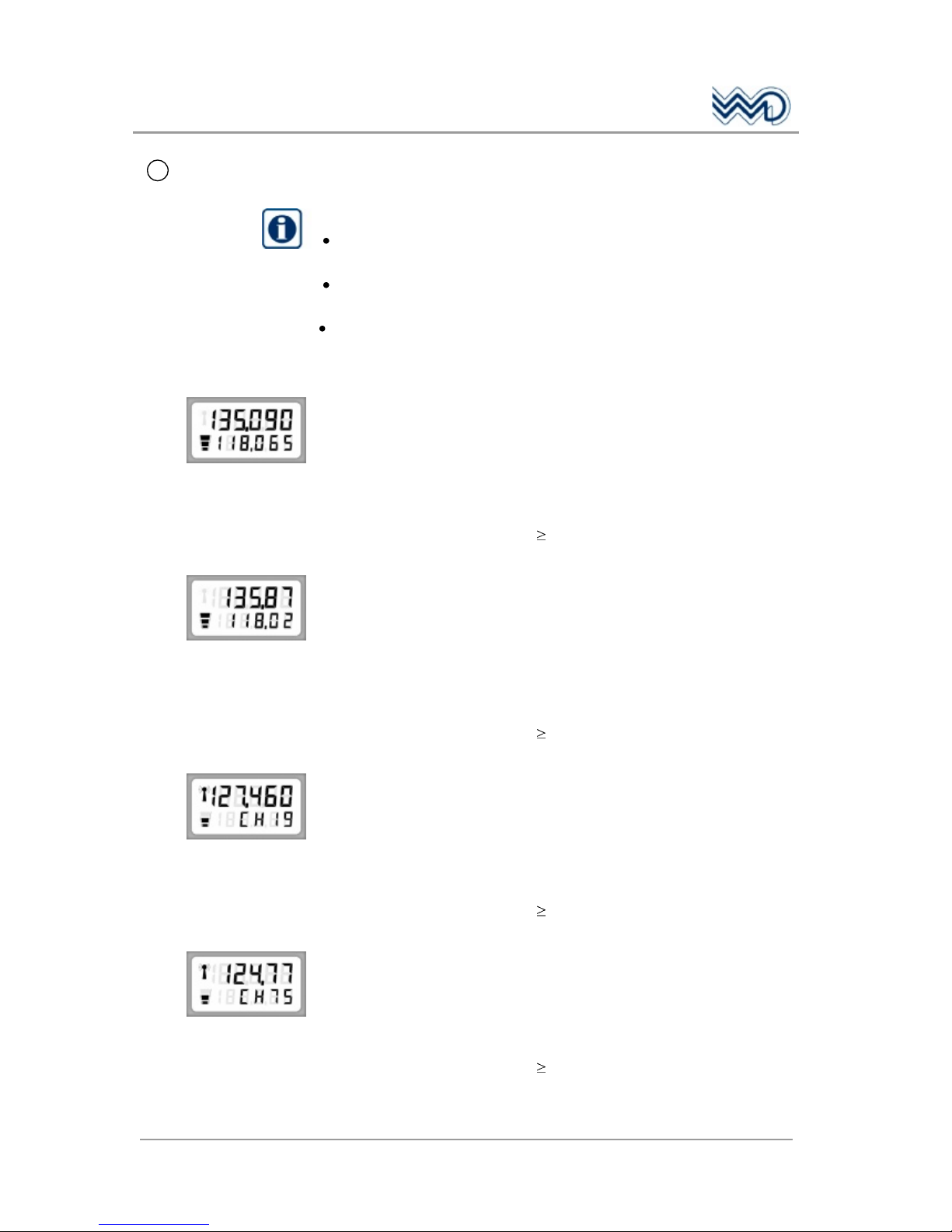
Examples:
Transceiver operates in the combined
8.33/25 kHz mode (6-digit display)
Upper line: USE channel name (display 135.090 = 135.0916
MHz transmit and receive frequency)
Lower line: STBY channel name (display 118.065 = 118.0666
MHz transmit and receive frequency)
Supply indicator: 3 segments: 12.7 Vdc, supply OK
TX indicator: OFF, radio receives.
Transceiver operates in the '25 kHz only' mode
(5-digit display)
Upper line: USE frequency (display
135.87 = 135.875 MHz transmit and receive
frequency)
Lower line: STBY frequency (display 118.02 =
118.025 MHz transmit and receive frequency)
Supply indicator: 3 segments: 12.7 Vdc, supply OK
TX indicator: OFF, radio receives.
Transceiver operates in the combined
8.33/25 kHz mode (6-digit display)
Upper line: USE channel name (display 127.460 = 127.4583
MHz transmit and receive frequency)
Lower line: Channel memory number (19) associated with the
above USE channel name
Supply indicator: 2 segments: 12.0 Vdc, battery ½ charged
TX indicator: ON, radio transmits.
Transceiver operates in the '25 kHz only' mode (5-digit display)
Upper line: USE frequency (display 124.77 = 124.775 MHz
transmit and receive frequency)
Lower line: Channel memory number (75) associated with the
above USE frequency
Supply indicator: 2 segments: 12.0 Vdc, battery ½ charged
TX indicator: ON
, radio transmits.

PORTABLE TRANSCEIVER FSG 90PC
2 Functional Description
May 2010
DITTEL D10075
15
STO button was pressed.
Upper line: Channel name to be stored
Lower line: Free channel memory number 07 (CH is flashing)
After pressing the STO button once more the channel name 121.875
(= 121.875 MHz) will be stored in the channel memory 07.
The last used display mode is displayed.
STO button was pressed.
Upper line: Channel name to be stored
Lower line: Channel memory number 17 (CH is flashing)
After pressing the STO button once more the channel name 121.375
(= 121.375 MHz) will be stored in the channel memory 17. A
previously stored channel name will be overwritten.
The last used display mode is displayed.
8
DC supply
Indicator
LED indicator to check the capacity of the built-in battery or external
DC supply.
When the red push-button is pressed
at least 3 LEDs should light up to indicate sufficient capacity of the
battery or DC supply.
and only two or less LEDs light up either the battery should be
recharged or the station should be powered by an external DC
source of sufficient capacity (e.g. vehicle battery).
the display of the transceiver is back-lit.
9
Loudspeaker 8 Ohm, 3 Watt, tropics-proof.
To make received signals audible; volume adjustable with
ON/OFF-VOL
control 1. Is not switched OFF when using a headset connected to
13
.
10
DANGER!
NEVER TRANSMIT inside airplanes, vehicles or
buildings without external antenna! Otherwise
electronic equipment can be interfered.
Antenna socket
CAUTION!
NEVER operate the radio without any antenna!
UHF type antenna socket SO 239, 50 Ohms.
Any 50 Ohms antenna with UHF type cable plug PL-259 and a
frequency range of 118 137 MHz minimum may be connected to
this antenna jack.
For portable use in the open field we recommend our spring steel
band antenna.
In aircraft or ground vehicles, an external antenna must be used.
For long range operation a base station folded top antenna,
grounded for lightning protection, is recommended.
PORTABLE TRANSCEIVER FSG 90PC
2 Functional Description
16
DITTEL D10075 May 2010
11
Antenna
compartment
When using our spring steel band antenna, A/N F10345, this antenna
can be kept there without disconnecting.
12
Microphone
compartment
When using our hand-hold microphone with built-in push-to-talk
switch, A/N F10041, this microphone can be kept there without
disconnecting.
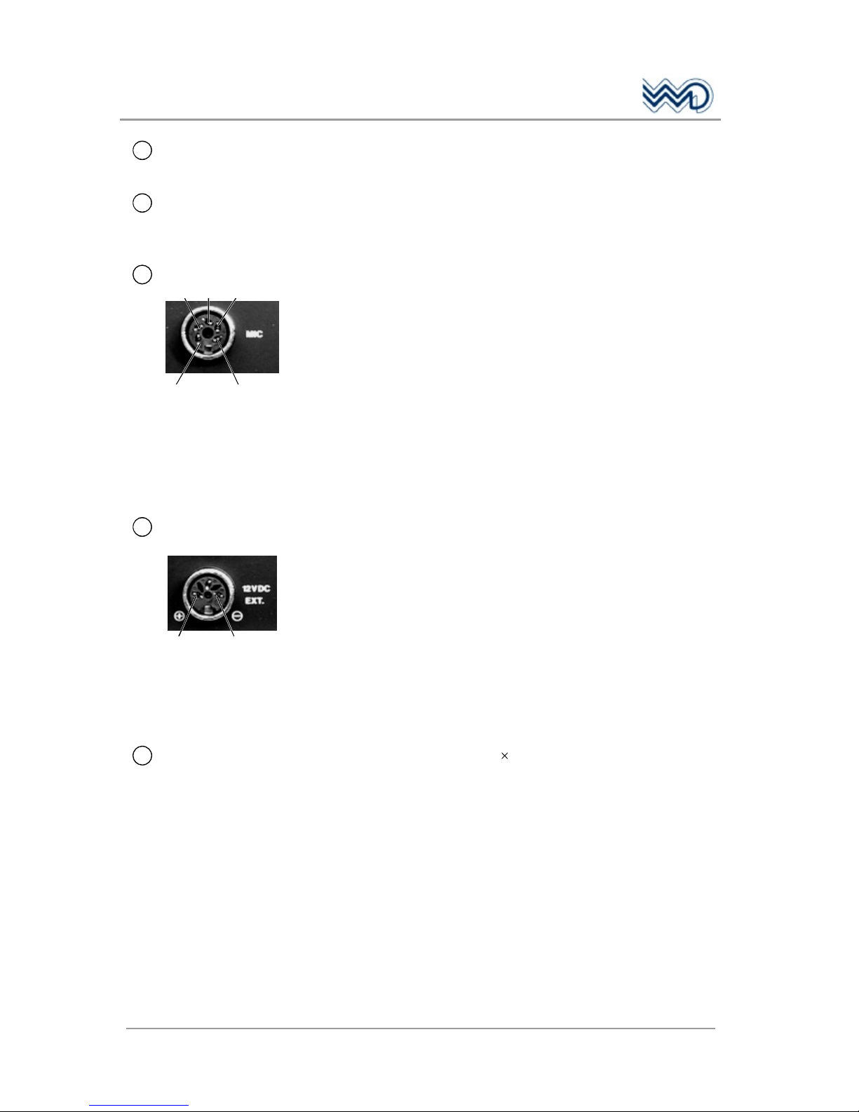
13
Microphone socket
(1)
(2) (3) (4)
(5)
5-pole twist-lock DIN socket to connect microphone, headphone and
PTT-switch.
Mating plug: article No. E08834
Any dynamic microphone (200 to 600 Ohms), headphone (ca.
300 Ohms), push-to-talk key, or dynamic type head-set can be
connected to this socket. Wiring refer to Section 6, "90 PC, Circuit
Diagram".
(1) Common Ground (PTT switch/Headphone)
(2) Dynamic microphone
(3) Headphone
(4) Microphone Ground
(5) Push-to-talk key
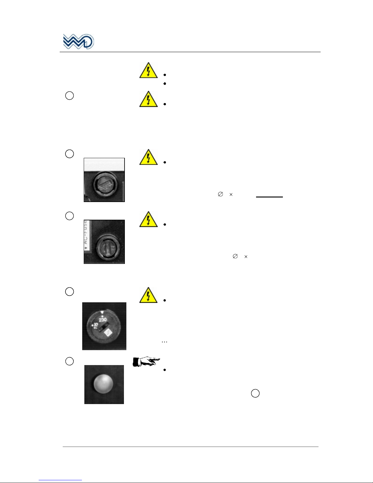
14
NEW SOCKET!
External Supply
(1) (3)
3-pole twist-lock DIN socket to supply the radio by external 12 Vdc
sources.
Mating plug: article No. E61933
The capacity of the built-in battery may not be adequate due to
frequent transmitting operations or very long operating times without
possibility to recharge. Radio operation can be enabled through an
external 12 Vdc power source such as an automobile battery via our
Car Cable F10393 which fits into the cigarette lighter socket of most
cars (minus on common ground).
(1) Plus 12 Vdc
(3) Minus 12 Vdc (Ground)
15
Fixing screws
Three cross recessed screws, M 3 8, to fix the transceiver in the
case.
PORTABLE TRANSCEIVER FSG 90PC
2 Functional Description
May 2010
DITTEL D10075
17
Rear panel:
WARNING!
Risk of electric shock!
DO NOT OPEN!
16
Mains cable
compartment
WARNING!
Changing the plug may only carried out by a
trained specialist -electrician-! Please observe
national safety regulations!
Contains the mains cable of the built-in battery charger, length of
cable: ca. 1.2 m.
17
WARNING!
Always turn OFF radio and disconnect mains plug
when replacing fuses!
DC Fuse
Fuse to protect the transceiver in case of heavy current.
Contains 1 glass cartridge fuse, 5 20 mm, 6,3 Amps, time-lag.
18
WARNING!
Always turn OFF radio and disconnect mains plug
when replacing fuses!
Mains Fuses
Fuses to protect the charging unit.
Contains 1 glass cartridge fuse each, 5 20 mm, 0.04 A time-lag.
The fuses fit for both mains voltages, no change required.
19
WARNING!
Always turn OFF radio and disconnect mains plug
when changing the mains voltage!
Mains selector
switch
The charging unit is factory set to 230 Vac mains voltage (position
230).
When 110 115 Vac mains is available, set the mains selector
switch by means of a coin or screwdriver to the 115 position.
20
CAUTION!
Always turn OFF the radio first when removing
from its case!
Ejector knob
After removing three cross-recessed screws 15 and the matching
plate on the front, the transceiver may be dismounted from its case by
pressing this ejector knob.

PORTABLE TRANSCEIVER FSG 90PC
2 Functional Description
18
DITTEL D10075 May 2010
 Loading...