

Page 1
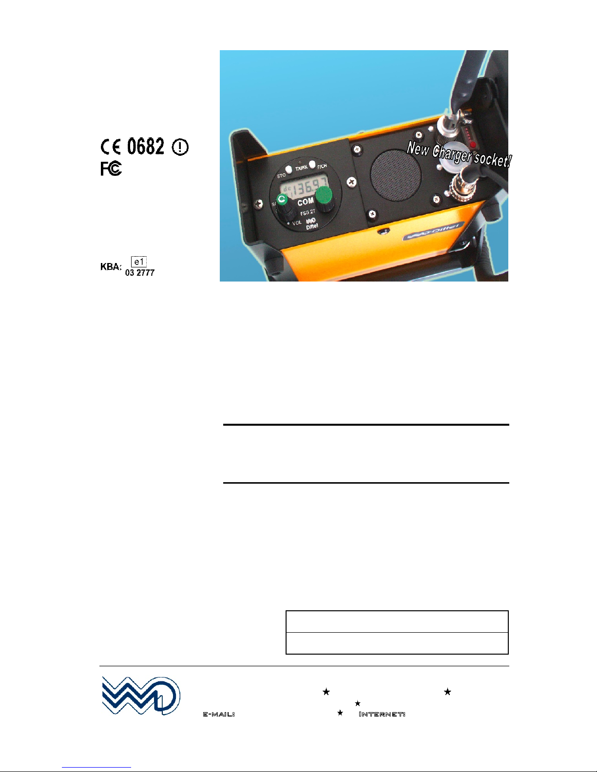
FSG 2T:
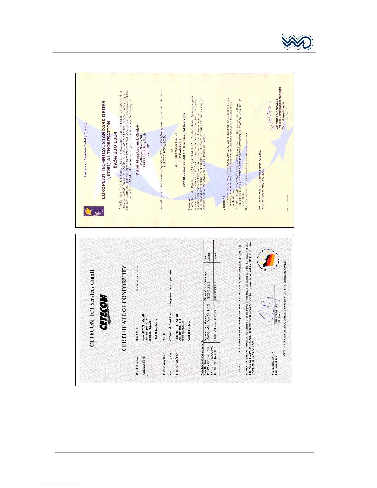
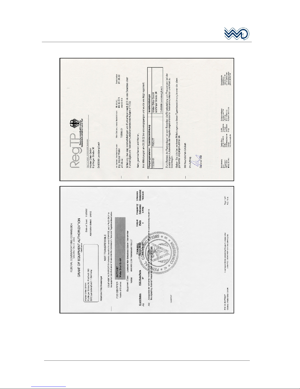
FCC ID: BVYFSG2T
LBA.O.10.911/103 JTSO
replaced by:
ESTO: EASA.21O.1304
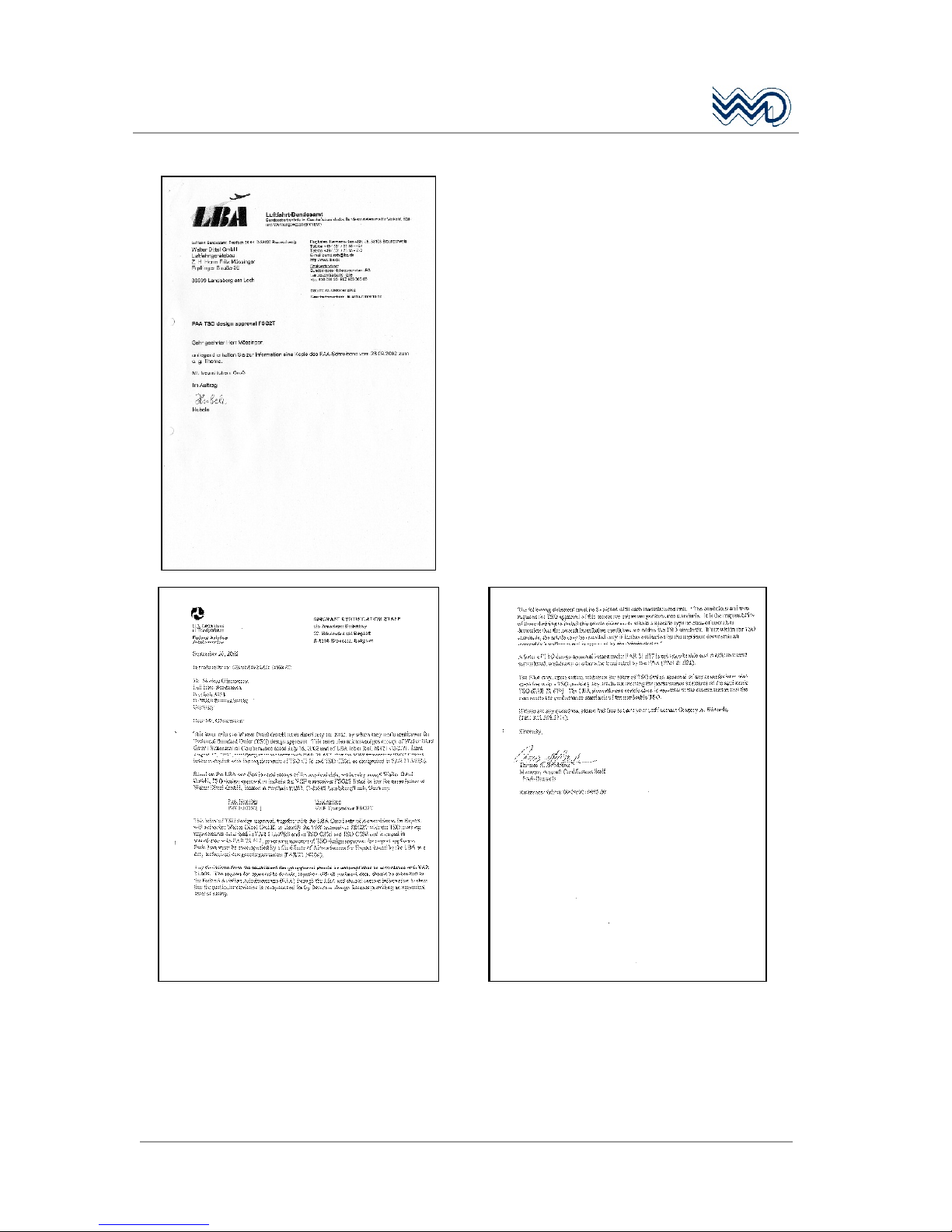
FAA: TSO C37d
TSO C38d
DFS-Nr.: D - 0002/2002
FSG 2T PS
Fixed / Portable / Mobile
VHF/AM Airband Transceiver
5 Watt 118.000 136.975 MHz
Operators Manual
Before operating the Transceiver, please
read this manual thoroughly!
Please observe the Safety Information!
Keep for further use!
Date of Issue May 2010
Revision 04
Document no.: OM 145.2T-EN Article no.: D10077
Owners Name:
Serial No. 2T PS:
Dittel Messtechnik GmbH
Avionics Division
Erpftinger Straße 36 86899 Landsberg Germany
Telephone +49 (0)8191 / 3351-0 Fax +49 (0)8191 / 3351-49
e-mail: [email protected] Internet: www.dittel.com
Dittel Messtechnik GmbH is certified to DIN EN ISO 9001:2000 and DIN EN ISO 14001:2005. It is an accredited manufacturer of
aeronautical equipment DE.21G.0100, maintenance facility DE.145.0245, and development facility ETSO-2C37e/ETSO-2C38e.
Page 2
FSG 2T PS
Portable VHF/AM Airband Transceiver
2
DITTEL D10077 May 2010
Manual Revision History
MANUAL OM 145.2T-EN
REVISION 04
This list gives you a RECORD OF REVISIONS of the
«Operators Manual»
due to
new hardware, mistakes or errors.
Revision DESCRIPTION/REASON FOR CHANGE Date
- NEW March 2003
01 New version of documen t Declaratio n of Conform ity appropriate to
the Germa n law (FTEG) of radio an d telecom te rminal equip ment. 12/05/03
02 FAA TSO numbers added at front page 17/09/03
03 Section 6, option cha nnel only mode added May 2005
04
Companys name changed into Dittel Messtechnik GmbH;
Extension of EC-Type Approval (Kraftfahrt-Bundesamt); new ESTO
document; 2-pole DC connector changed into 3-pole DC connector
due to ceased production, resulting in some new article numbers
May 2010
Page 3

FSG 2T PS
Portable VHF/AM Airband Transceiver
May 2010 DITTEL D10077
3
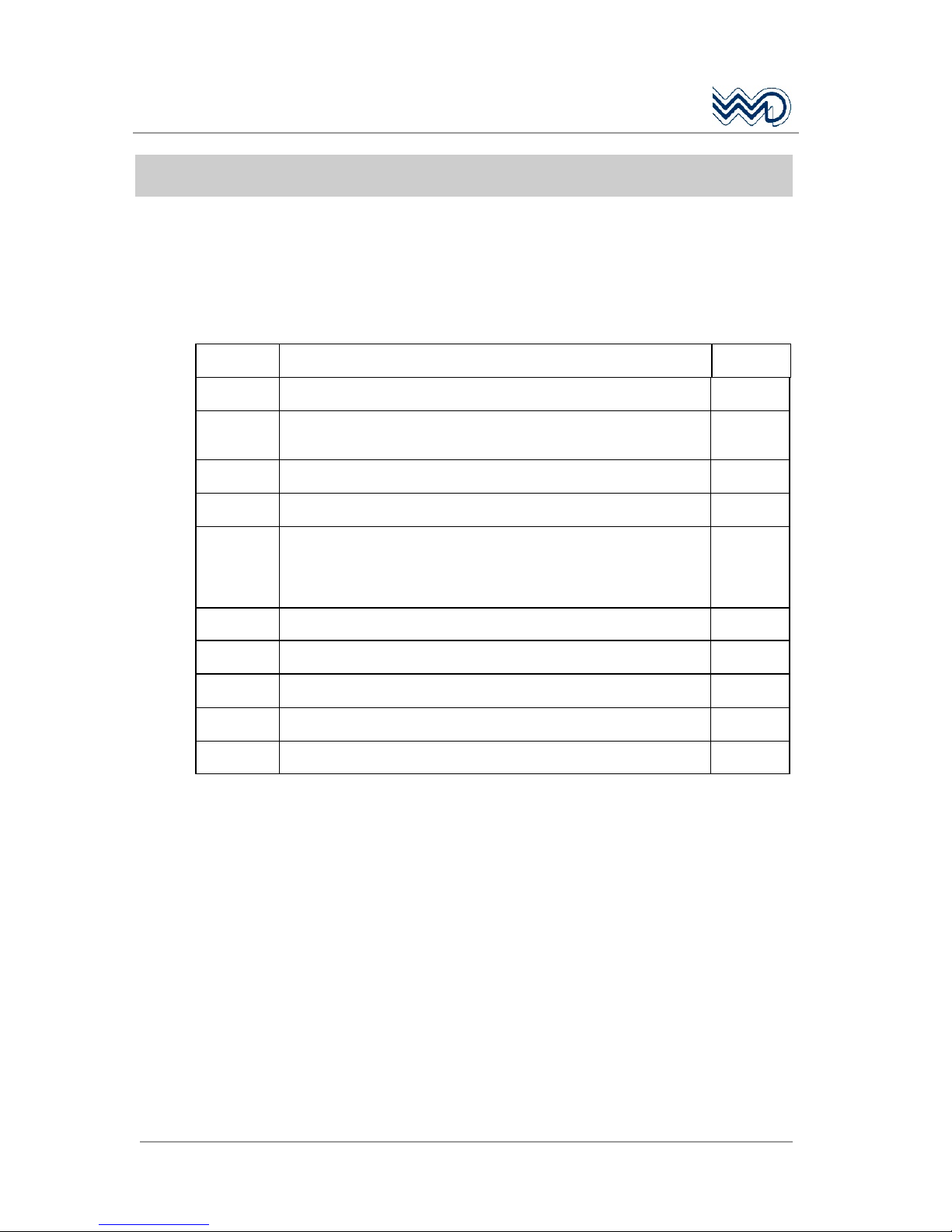
Table of Contents
Manual Revision History....................................................................2
Table of Contents...............................................................................3
Abbreviations.....................................................................................5
1 For Your Safety........................................................................7
1.1 Used Symbols....................................................................................9
2 General Description ..............................................................11
2.1 About this document.........................................................................11
2.2 Application & Description of the FSG 2T PS.................................... 11
2.3 Equipment required but not supplied................................................12
2.4 System and Type Approval Information ...........................................12
2.5 Re-calibration Information ................................................................13
2.6 Operating License............................................................................ 13
2.7 Optional Accessories and Spare Parts.............................................14
3 Functional Description..........................................................15
3.1 Introduction....................................................................................... 15
3.2 Operator's Controls and Indicators................................................... 15
3.3 Frequency Display............................................................................ 20
3.4 Error Codes ......................................................................................21
4 Operation................................................................................23
4.1 Introduction....................................................................................... 23
4.2 Battery Check................................................................................... 23
4.3 Battery Charging...............................................................................25
4.4 Antenna - Antenna jack SO 239....................................................... 26
4.5 Microphone Socket........................................................................... 26
4.6 Turning ON - Selecting Frequency - Audio Volume..........................27
4.7 Receive (Listen) Operation............................................................... 29
4.8 Transmit (Talk) Operation.................................................................30
4.9 Memory Programming...................................................................... 32
4.9.1 Programming while in the DIRECT TUNE MODE:........................... 32
4.9.2 Programming while in the CHANNEL MODE:.................................. 33
4.10 Lighting the Frequency Display and Front Panel.............................. 34
4.11 Turning OFF the radio...................................................................... 34
4.12 External Power Supply..................................................................... 34
4.13 Removing & Installing the Transceiver............................................. 34
4.14 Battery Operating Times................................................................... 35
4.15 Emergency Operation....................................................................... 35
4.16 Siting................................................................................................. 36
4.17 Base Operation................................................................................. 36
4.18 Troubleshooting................................................................................ 36
Page 4

FSG 2T PS
Portable VHF/AM Airband Transceiver
4
DITTEL D10077 May 2010
Table of Contents
5 Technical Data FSG 2T PS ................................................... 39
5.1 General .............................................................................................39
5.2 Dimensions, Weight ..........................................................................39
5.3 Power Supply, Fuses ........................................................................39
5.4 Detailed Receiver Specification.........................................................40
5.5 Detailed Transmitter Specification.....................................................41
5.6 Environmental Performance Classification........................................42
6 Option "Channel ONLY Mode" ............................................ 45
6.1 Activating the option "Channel only Mode".......................................45
Appendix, Certificates..................................................................... 47
Copyright Service Information .................................................... 55
Page 5

FSG 2T PS
Portable VHF/AM Airband Transceiver
May 2010 DITTEL D10077
5
Abbreviations
Ohm
°C Degrees Centigrade
°F Degrees Fahrenheit
A/C
Aircraft
A/N Article Number
(Dittel Messtechnik
GmbH)
AGC Automatic Gain Control
Ah Ampere hour
AM Amplitude Modulation
ANT Antenna
Ass'y Assembly
AWG American Wire Gauge
ccw
Counter-clockwise (turn left )
CH Channel
cw
Clockwise (turn right )
dB Decibel
dia. Diameter
EMF Electromotive Force (voltage of
an open circuit)
F/CH Frequency/Channel
FL Flight Level
g Acceleration due to gravity
GND Ground
HI High Power
Hz Hertz
ICAO
International Civil Aviation
Organization
IF Intermediate Frequency
kHz Kilohertz
LCD Liquid Crystal Display
LED Light Emitting Diode
LO Low Power
LOS Line-Of-Sight
m Modulation
mA
Milliampere
MD Mode
MHz Megahertz
MIC Microphone
mW Milliwatt
NM Nautical miles (1.852 km)
nW Nanowatt (10-9)
PEP Peak Envelope Power
PLL Phase-Locked Loop
ppm Parts per million
PTT Push-To-Talk
pW Picowatt (10
-12
)
RF Radio Frequency
rms
Effective value
(root mean square)
RX Receive
S+N/N Signal-to-Noise Ratio
SINAD
Ratio:
Signal noise distortion
noise distortion
SPKR Loudspeaker
SQ Squelch
STBY Standby
STO Store
SWR Standing-Wave Ratio
THD Total Harmonic Distortion
TOT Time out timer
TX Transmit
VA Volt-ampere, apparent power
Vac Volts, alternating current
VCO Voltage-Controlled Oscillator
Vdc Volts, direct current
VFO Variable-frequency oscillator
VHF Very-High Frequency
VOL Volume
VSWR Voltage Standing-Wave Ratio
W Watt, real power
Page 6

FSG 2T PS
Portable VHF/AM Airband Transceiver
6
DITTEL D10077 May 2010
Notes:
Page 7
FSG 2T PS
Portable VHF/AM Airband Transceiver
May 2010 DITTEL D10077
7
1 For Your Safety
Every radio, when transmitting, radiates energy into the atmosphere
that may, under certain conditions, cause the generation of sparks. All
users of our portable radios should be aware of the following warning:
Do not operate this portable radio in an explosive atmosphere
(petroleum fuels, solvents, dust, etc.)!
During normal use, the radio will subject you to radio frequency
energy substantially below the level where any kind of harm is
reported.
There are no user replaceable parts inside the FSG 2T PS! If the
radio fails it must be returned to a Dittel Messtechnik GmbH
approved repair facility!
The licensee of a radio station is responsible at all times for the
proper operation of the station. Radio operators should use the
following guidelines to make this radio a useful tool for safe and
efficient communication:
DO NOT transmit when the antenna is very close to, or touching,
exposed parts of the body, especially the face and eyes. Persons
with pacemakers should be aware that proper functioning may be
affected when in the vicinity of the antenna!
DO NOT transmit without antenna connected.
DO NOT operate the radio on an unprotected power supply.
Replace a blown fuse only against correct type with specified
nominal value. Investigate the cause.
DO NOT transmit on a busy channel.
DO NOT press the transmit (PTT) key when not actually desiring
to transmit.
DO NOT transmit with the antenna inside aircraft or vehicle. This
may cause malfunction of onboard avionics, trigger the vehicle
airbag or interfere onboard instruments! Always operate the
portable radio FSG 2T PS with a suitable outdoor / external
antenna! Assure appropriate lightning protection / grounding where
(elevated) outdoor antennas are used.
DO NOT operate the radio whilst driving. It should also be noticed
that even the use of a hand held microphone while driving could
constitute an offence under the Road Traffic Regulations in certain
countries.
DO NOT allow children to play with any radio equipment
containing a transmitter.
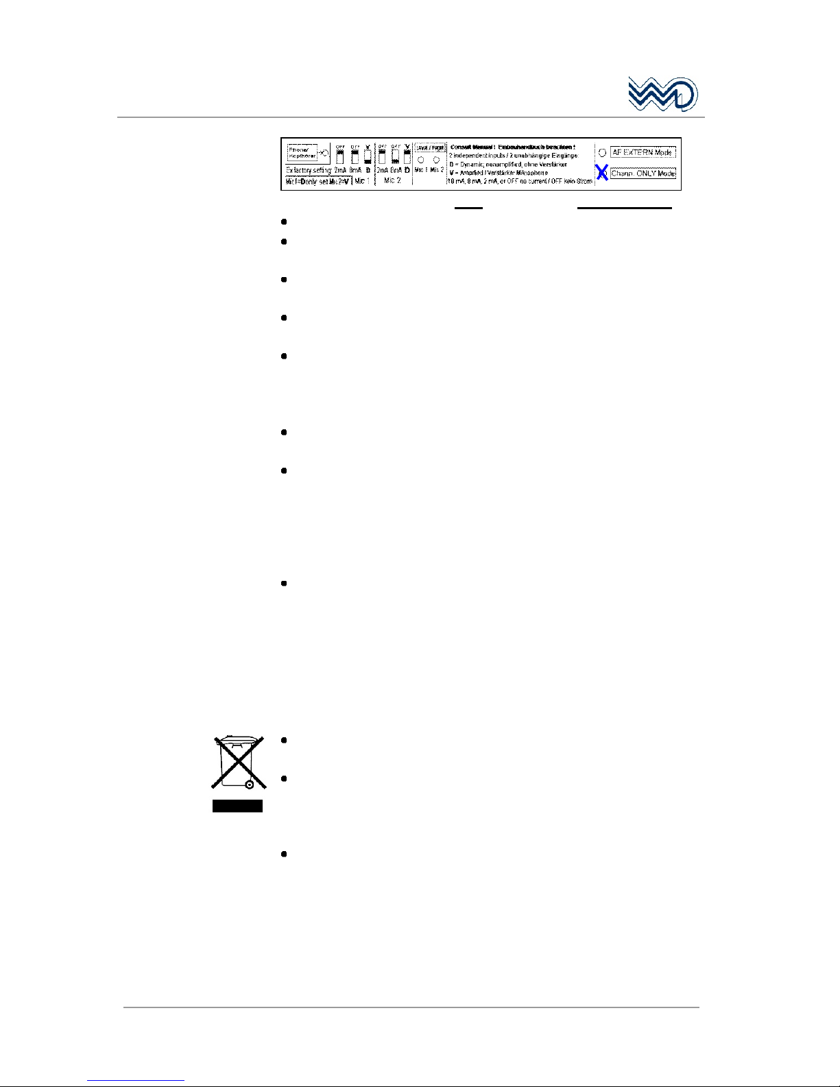
DO NOT use a radio FSG 2T for airborne operation which is
marked as Chann. ONLY Mode:
Page 8
FSG 2T PS
Portable VHF/AM Airband Transceiver
8
DITTEL D10077 May 2010
Such a radio is allowed only for the use as ground station!
Always turn OFF the radio when installing or removing the unit!
Always turn OFF the radio when starting nearby engines or
vehicles!
The FSG 2T PS should be used exclusively for aviation related
communication purposes.
Unauthorized modifications and changes of the system are
forbidden.
Sufficient speech volume is very important. While the lips are very
close and facing the microphone, speak loud and clear. Proper
speech level is indicated by the yellow flickering LED on the
FSG 2T front panel.
In vehicles a suitable noise canceling microphone or headset shall
be used.
Prior to any use verify proper FSG 2T PS functions by means of a
short radio check. It has however to be taken into account that with
a faulty antenna or its cable this communication test may
absolutely turn out positive at the airfield or in short distance to the
ground station. But at a distance of 2 to 6 miles, a faulty antenna
and / or cables will cause communication breakdown!
Push-to-Talk keys may stick occasionally.
The transmission signaling RED or flickering YELLOW LED shall
be turn to CLEAR or GREEN when releasing the PTT key.
However, after more than two minutes continuous transmitting (by
stuck button or operator caused), the built-in transmit time-outtimer disables the transmitter in order to avoid continuous channel
blocking. A continuously flashing display warns the user. Refer to
appropriate hints in this manual.
PB
The portable airband transceiver FSG 2T PS contains a sealed
lead-acid battery (identification "Pb").
In most countries it is illegal to discard a lead-acid battery except
by delivery to a retailer, a distributor, a manufacturer, or a
collection, recycling, or smelting facility approved by the
department.
NEVER dispose worn out lead-acid batteries with the household
garbage.
Page 9
FSG 2T PS
Portable VHF/AM Airband Transceiver
May 2010 DITTEL D10077
9
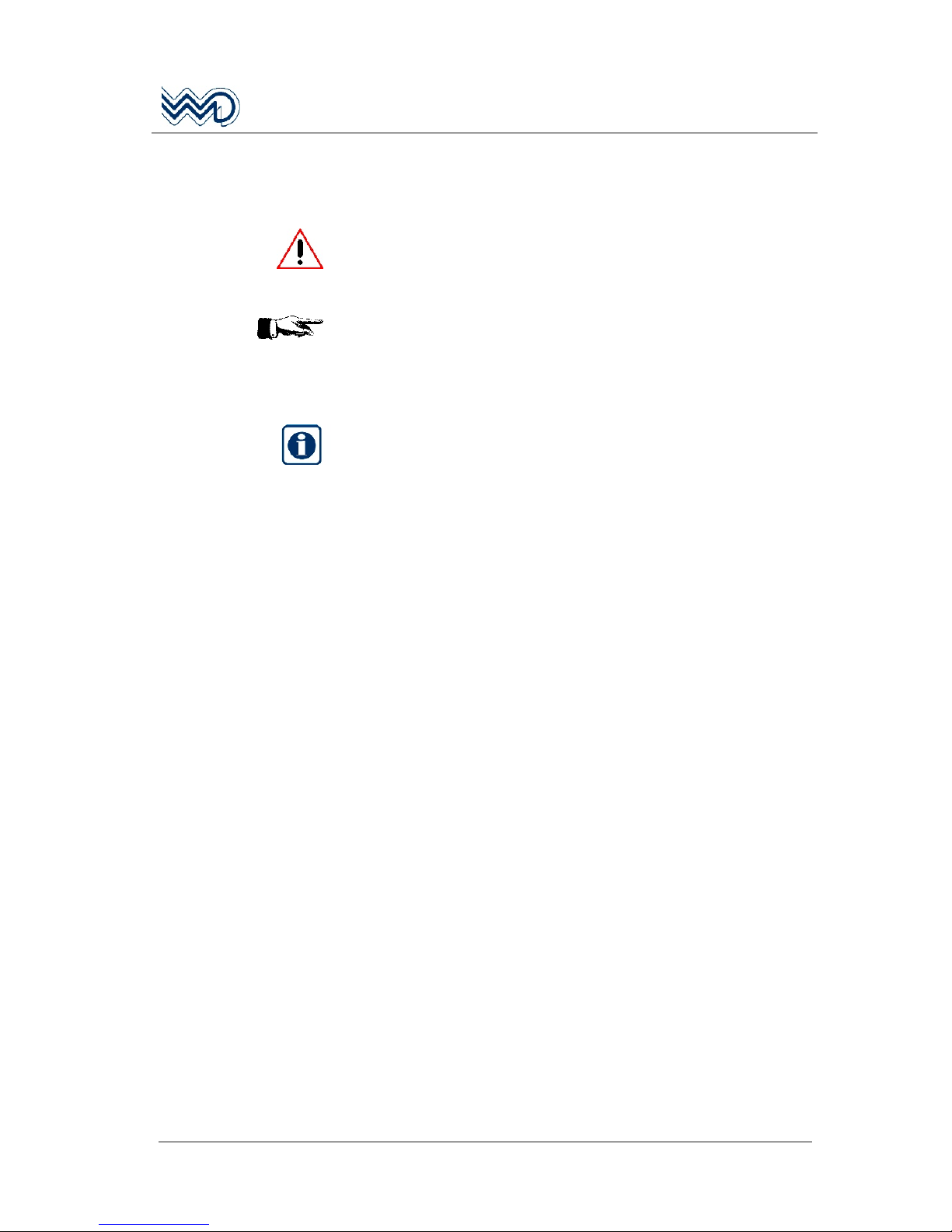
1.1 Used Symbols
In this manual the following symbols are used:
WARNING!
describes an immediate threatening danger! Failing to observe the
note may cause death or heaviest injuries.
CAUTION!
describes a special note for operation. Failing to observe the note
may cause damage of the transceiver and / or stored data may be
deleted!
IMPORTANT!
describes explanations and other useful hints. Failing to observe the
note may cause degraded performance and / or unsatisfying
operation!
Page 10

FSG 2T PS
Portable VHF/AM Airband Transceiver
10
DITTEL D10077 May 2010
Page 11

FSG 2T PS
Portable VHF/AM Airband Transceiver
May 2010 DITTEL D10077
11
2 General Description
2.1 About this document
This operator's manual contains operating instructions for the fixed/
portable/ mobile VHF/AM Airband Transceiver FSG 2T PS of Dittel
Messtechnik GmbH, 86899 Landsberg, Germany.
2.2 Application & Description of the FSG 2T PS
The portable battery powered VHF/AM Airband Transceiver
FSG 2T PS allows independent operation as an airborne or ground
radio. Stationary, portable or mobile applications are possible. It
consists of a portable case PS (A/N F10386) and a VHF/AM COM
Transceiver FSG 2T (A/N F10350), which can be simply inserted and
positioned.
This radio is working within the airband frequency range of 118.000
MHz to 136.975 MHz in 25 kHz increments (760 channels). The
operating mode is Simplex, i.e. transmitting or receiving only in turns
(two way communication).
The built-in rechargeable battery allows an independent operation of
up to 130 hours (refer to paragraph 4.14, Battery Operating Times).
Continuous operation is possible by supplying the radio externally,
from a vehicle or aircraft DC supply. Microphone and antenna are
plugged via twist locked and screwed cap connectors. External
antennas, too, can be advantageously used.
For airborne and ground application two display modes are user
selectable:
FREQUENCY MODE:
Active Frequency and actual supply voltage are shown at the
display. Turning / pushing the F/CH knob changes frequency.
CHANNEL MODE:
Active Channel Number (1 20) and associated Frequency are
shown at the display. Turning the F/CH knob changes preset Channel
Number and associated Frequency. Reprogramming without
restriction.
Only for ground based
operation (CH ONLY Mode):
Optionally a particular mode can be set where the operation is limited
to use only preset channels. To set this mode the radio has to be
opened. This may only be performed by an approved repair
facility!
The unit features 20 non-volatile channel memories, 2 display modes,
Sidetone via headphone, three color status LED, supply voltage
indication at the back-lit display, TX time-out timer (2 minutes), a
battery supply test, DIN connectors to plug dynamic, non-amplified
Page 12

FSG 2T PS
Portable VHF/AM Airband Transceiver
12
DITTEL D10077 May 2010
microphones and external power supply, and a built-in loudspeaker.
The lock-in type carrying handle completes our robust FSG 2T PS
unit.
2.3 Equipment required but not supplied
Vertically polarized VHF airband antenna, frequency range
minimum 118 to 137 MHz, 50 Ohm, e.g., DITTEL spring steel band
antenna, A/N F10345.
Dynamic Microphone 30 to 600 Ohm, e.g., WD handheld dynamic
microphone with PTT-key, 5-pole DIN plug and coiled cord, A/N
F10346.
Automatic Battery Charger, e.g. DITTEL DL-50A, 115 Vac /
230 Vac, output 13.8 Vdc / 600 mA, A/N F10385.
When operating the unit on a 24 Vdc source a suitable 14
Vdc/12 Vdc Converter of at least 3 Amps must be used!
2.4 System and Type Approval Information
The VHF/AM Airband Transceiver FSG 2T complies with ICAO 25 kHz
channel spacing and also meets applicable National and International
Type Approval requirements, for any airborne and ground operation:
JTSO Authorization LBA.O.10.911/103 JTSO (LBA Luftfahrt-
Bundesamt), replaced by ETSO Authorization EASA.21O.1304
(2009), is based on EUROCAE ED-23B Airborne requirement (25
kHz ONLY CH spacing).
FM Immunity requirements according to ICAO ANNEX 10 against
FM Broadcast RF Interference.
Audio filtering required in areas with CLIMAX operation in 25 kHz
channel spacing.
Associated EUROCAE ED-14D / RTCA DO-160D Environmental
requirements for Fixed Wing and Helicopter aircraft.
Associated EUROCAE ED-12B Software requirements based on
ED-12B, Level C.
Type Approval requirements for ground operation, meeting ETSI
EN 300 676.
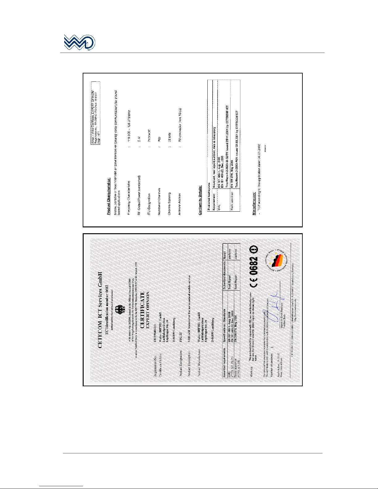
CE Conformity requirements for ground operation, meeting ETSI
EN 301 489-1 and -22.
DFS (Deutsche Flugsicherung) No. D - 0002/2002 German
(ground) Type Approval.
DIN / ISO 7637-1 Dc supply in 12 Vdc vehicle,
KBA No.: e1 03 2777.
FCC Compliance with Part 15 (receiver) and Part 87 (transmitter),
FCC ID: BVYFSG2T.
FAA / TSO Authorization
Page 13
FSG 2T PS
Portable VHF/AM Airband Transceiver
May 2010 DITTEL D10077
13
2.5 Re-calibration Information
IMPORTANT!
For the first time after three years, FSG 2T equipment for
ground applications requires checking and re-calibration of
the high precision reference frequency (tolerance better than
±10 ppm).
For airborne applications, no frequency re-calibration is
necessary, since applications in the 25 kHz channel spacing
require a frequency accuracy tolerance of less than ± 20 ppm.
All tolerances include the full operating temperature range of
-20°C ... +55°C / -4°F ... +131°F.
Checking and re-calibration must be performed by the
equipment manufacturer or through authorized and approved
avionics services!
2.6 Operating License
IMPORTANT!
Depending on national regulations, VHF/AM ground and / or
VHF/AM airborne operation may require an individual national
operating license. Such license is usually granted by the
responsible National Telecommunications Authority, through
suitable application forms.
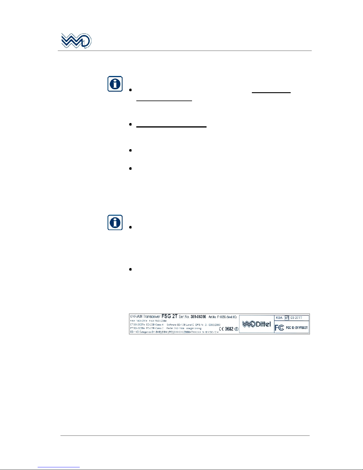
Aircraft registration, operator's name, address and operating
license payment details, radio type / model, Serial number,
ESTO number EASA.21O.1304, and DFS number D-0002/2002,
or, when applicable, the FCC ID number BVYFSG2T.
Example:
Page 14

FSG 2T PS
Portable VHF/AM Airband Transceiver
14
DITTEL D10077 May 2010
2.7 Optional Accessories and Spare Parts
A/N Description
F10385
DL-50A, automatic lead-acid battery charger, input: 115 Vac/230 Vac,
output: 13.8 Vdc/600 mA, cable and 3-pole DIN plug
F10345 Spring steel band antenna 118 - 137 MHz, swivel type, UHF-
connector PL-259
W00043 Magnet mount vehicle rod antenna 118 - 137 MHz, incl. 4 m/13 ft
cable, and UHF connector PL-259
W00114 Mobile Whip Antenna with shock spring, 118 - 137 MHz, incl. 5 m/
16.5 ft cable, w/out UHF connector PL-259
F10314
Balloon antenna BFA 1, 118 - 137 MHz, weatherproof - flexible - high
efficiency, including 3 m/10 ft cable and UHF connector PL-259
F10346 Dynamic hand-held microphone incl. PTT-switch, coiled cord and
5-pole plug
F10042 Dyn. hand-microphone/loudspeaker with PTT-switch, coiled cord and
5-pole DIN plug
F10125 Inline PTT-switch (U-94 A/U), coiled cord, 5-pole DIN plug, to connect
headset W00048, clip allows attaching to clothing
W00048 Dynamic headset with PJ-plug, fits inline PTT-switch
F10393 Car Cable, coiled cord, incl. 3-pole DIN plug to supply station from
12 Vdc car battery (fits cigarette lighter socket, minus = ground)
S20000 Converter 24 Vdc to 12 Vdc, 4 Amps, to operate the base Station
from 24 Vdc sources like truck batteries etc.
E61933 3-pole twist-lock DIN Connector, to fit into 12 Vdc socket of carrying
case PS.
E08834 5-pole twist-lock DIN Connector, to fit into MIC socket of carrying
case PS.
E61181 Valve-regulated lead acid battery, 12 Vdc, rated capacity 7.2 Ah
Page 15
FSG 2T PS
Portable VHF/AM Airband Transceiver
May 2010 DITTEL D10077
15
3 Functional Description
3.1 Introduction
This section includes a functional description of each switch, push
button, knob, socket, indicator and display located on the front of the
FSG 2T PS,
together with operating instructions.
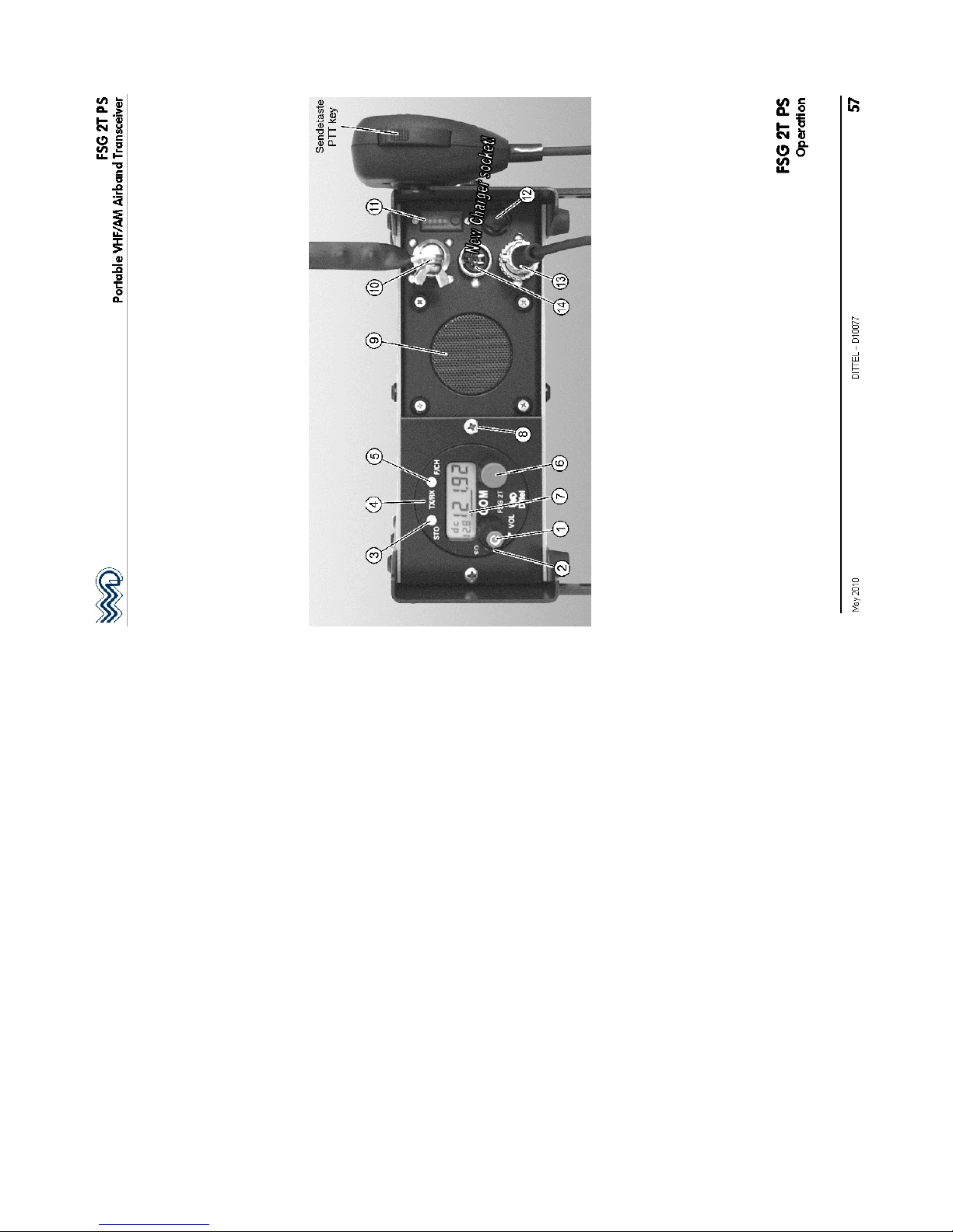
3.2 Operator's Controls and Indicators
A front view of the FSG 2T PS is given on the last page of this manual.
Please fold out the back flap when reading the operating instructions.
Each position number of a control, knob, switch, etc., corresponds to
the number of control, knob, switch, etc., given below.
Control Description / Function
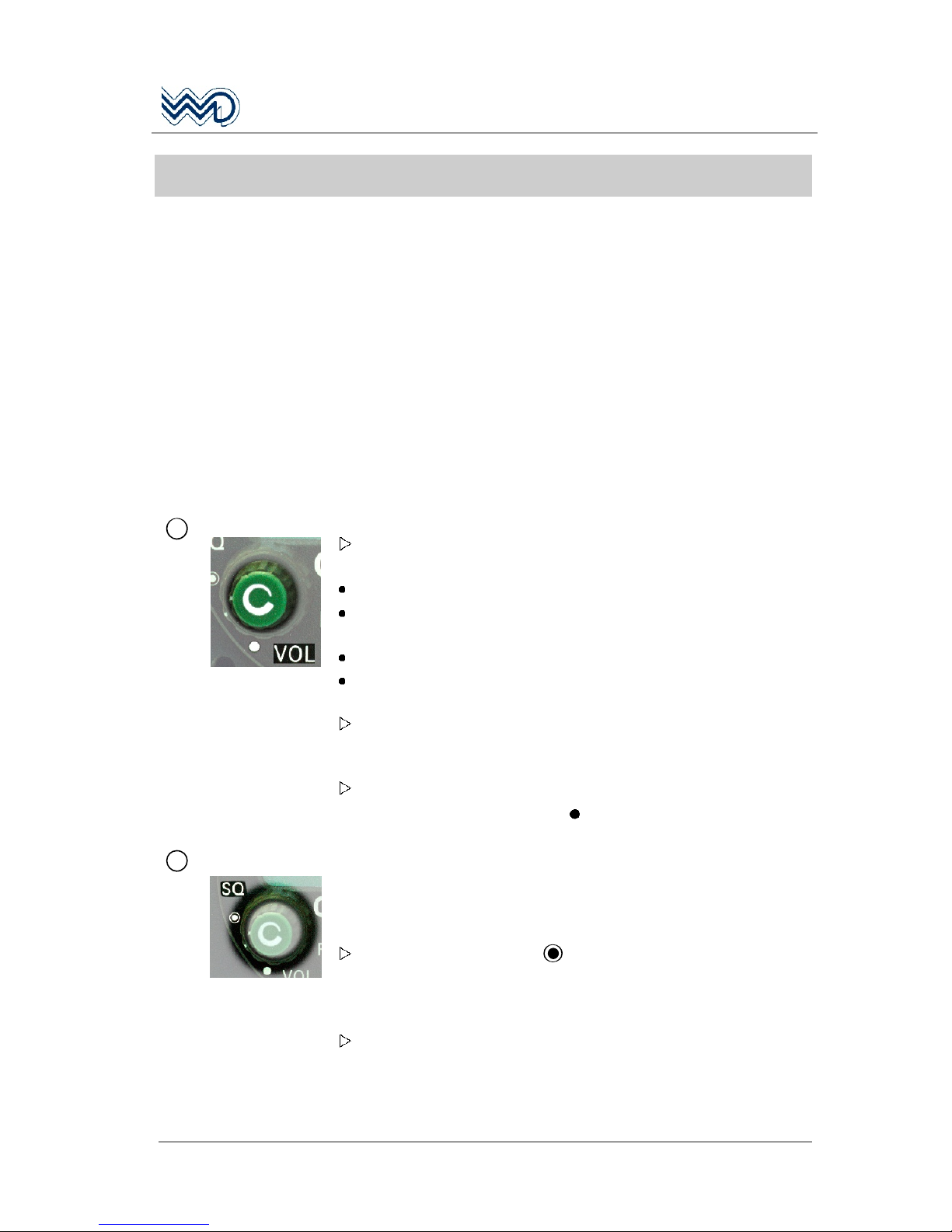
1
VOL
Rotary switch and control (inner knob)
To turn ON the radio, rotate the VOL knob clockwise from the OFF
position (dot). When power is activated
the front panel TX/RX LED lights up green momentarily, then
all segments of the display are visible for a short time, to verify
their operation.
The display shows the firmware version and then
the operating mode, which was used before last turning OFF or
Power OFF: The radio is now ready for use.
Rotating the VOL knob clockwise (cw) increases - turning counter-
clockwise (ccw) decreases the audio volume audible via the built-
in loudspeaker or a connected headphone.
To turn OFF the radio rotate the VOL knob fully counter-clockwise
(ccw) to the OFF position (dot ). Blank display.
2
SQ
(SQUELCH)
Rotary control (outer ring)
After turning ON the radio FSG 2T the automatic squelch is active
depending on the SQ knob position.
Standard Operating Mode:
Set the SQ
knob to the dot position, the Squelch (mute)
threshold is approximately 1 µV. No Receiver noise should be
audible during Standby. Only received signals above the SQ
threshold are audible.
Rotating the SQ knob fully counter-clockwise (ccw) puts the radio
into the SQ-OFF mode (overrides the automatic squelch). Basic
receiving noise is then audible during Standby. This adjustment
gives maximum receiving range. Slightly increased current
Page 16
FSG 2T PS
Portable VHF/AM Airband Transceiver
16
DITTEL D10077 May 2010
consumption.
Rotating the SQ knob clockwise (cw) achieves Receiver muting.
To eliminate ignition noise or RF interference adjust the SQ knob
up to the full clockwise (cw) position. This gradually increases the
required RF signal to exceed the SQ threshold (max. threshold
5 µV / -93 dBm).
3
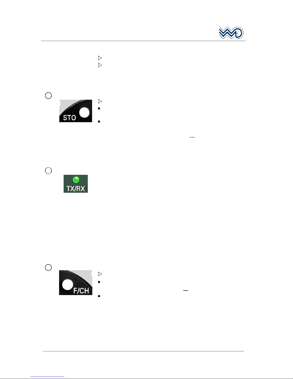
STO (STORE) Push button
When pressing the STO button (within approx. one minute)
storing of a frequency in one of the memory channels is initiated,
or
storing of a frequency is confirmed (at least 1 sec).
20 frequencies may be programmed in non-volatile memory
channels. The channel memory numbers (1 20) are user
programmable.
If the FSG 2T is set to CH ONLY Mode this STO button is without
function!
4
TX/RX LED
The TX/RX 3-color Status LED on the front panel indicates the
following:
CLEAR...................indicates a Standby condition or radio is OFF.
STEADY RED ..........indicates a Transmit condition without or too low
modulation.
FLICKERING
YELLOW.................indicates a Transmit condition with proper
microphone signal / modulation.
STEADY
YELLOW.................indicates a Transmit condition with too much
modulation or background noise (microphone
sensitivity too high)
STEADY GREEN......indicates a Receive condition; Squelch is open
automatically (or set OFF manually).
5
F/CH Button Push button
When pressing the F/CH button
while in DIRECT TUNE MODE (MHz or kHz is underscored), this will
change the radio into CHANNEL MODE, or
while in CHANNEL MODE (Channel number is underscored), this will
change the radio into DIRECT TUNE MODE.
The last used frequency in each mode remains. This allows toggling
between two operational frequencies by just pressing the F/CH button.
If the FSG 2T is set to CH ONLY Mode pressing the F/CH button will
show the DC supply voltage for 5 seconds (instead of continuous
channel number).
Page 17
FSG 2T PS
Portable VHF/AM Airband Transceiver
May 2010 DITTEL D10077
17
6
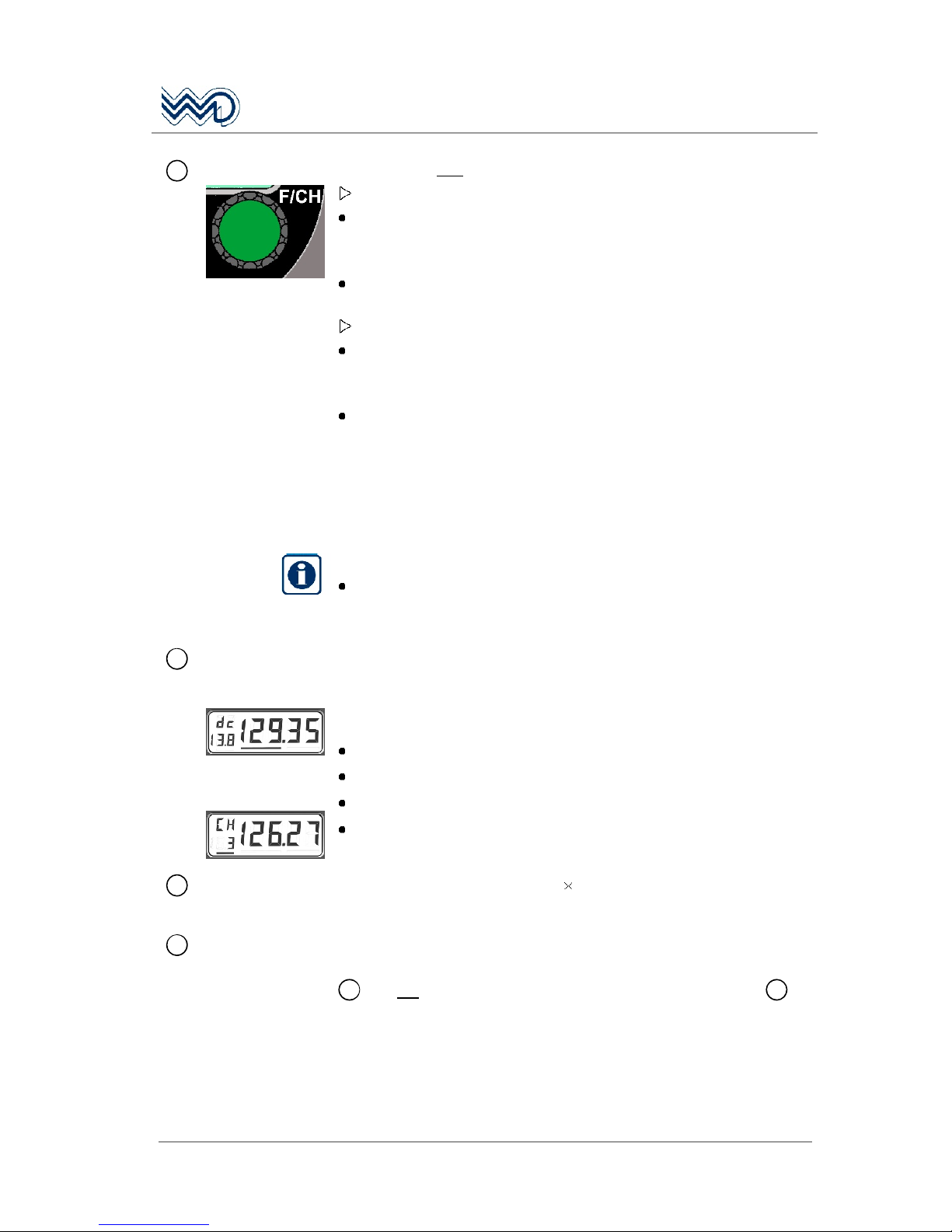
F/CH
Knob
Rotary control and push button = dual function
Pressing the F/CH knob once
while in the DIRECT TUNE MODE changes the access from kHz to
MHz or vice versa from MHz to kHz. The active access to MHz or
kHz is underscored by a cursor.
While in the CHANNEL MODE or CH ONLY pressing the F/CH knob is
without function.
Rotating the F/CH knob
while in the DIRECT TUNE MODE will increment or decrement the
MHz or kHz portion of the active frequency with rollover at each
band edge.
while in the CHANNEL MODE changes the channel memory number
and associated frequency. All channel numbers (1 to 20) can be
used.
If the FSG 2T is set to CH ONLY Mode rotating the F/CH knob changes
the channel memory number and associated frequency. All 20
channel numbers are adjustable.
IMPORTANT!
Only ONE control element may be operated at a time. If more
than one element is operated simultaneously, function change
is blocked.
7
Frequency Display
DIRECT TUNE
MODE
CHANNEL MODE
or CH ONLY
Frequency Display, the 5-digit Liquid Crystal Display (LCD) can be
back-lit.
Frequency display complies with ICAO rules.
Initial boot at Switch-ON / Power ON
Displays all segments for 2 seconds
Clear Display for 0.5 seconds
Shows Firmware Version for 0.5 seconds
Goes to last user setting (operating mode and frequency, refer to
paragraph 3.3).
8
Fixing Screws
Two cross recessed screws, M 4 8, to fix the transceiver in the
case.
9
Loudspeaker 8 Ohm, 3 Watt, tropics-proof.
To make received signals audible; volume adjustable with VOL control
1
. It is not switched OFF when using a headset connected to 13.
Page 18

FSG 2T PS
Portable VHF/AM Airband Transceiver
18
DITTEL D10077 May 2010
DANGER!
NEVER TRANSMIT inside airplanes, vehicles or
buildings without external antenna! Otherwise
electronic equipment can be interfered.
10
Antenna Socket
CAUTION!
NEVER operate the radio without any antenna!
UHF type antenna socket SO 239, 50 .
Any 50 Ohms antenna with UHF type cable plug PL-259 and a
frequency range of 118 137 MHz minimum may be connected to
this antenna jack.
For portable use in the open field we recommend our spring steel
band antenna.
In aircraft or ground vehicles, an external antenna must always be
used.
For long range operation a base station folded top antenna, grounded
for lightning protection, is recommended.
11
DC Supply
Indicator
LED indicator to check the capacity of the built-in battery or external
DC supply.
When the red push-button is pressed
at least 3 LEDs should light up to indicate sufficient capacity of the
battery or DC supply.
and only two or less LEDs light up either the battery should be
recharged or the station should be powered by an external DC
source of sufficient capacity (e.g. vehicle battery).
the display 7 and the front panel of the transceiver is back-lit.
12
CAUTION!
Always turn OFF the radio and disconnect battery
charger when replacing fuses!
DC Fuse
Fuse to protect the transceiver in case of heavy current.
Contains 1 glass cartridge fuse, 5 20 mm,
6.3 Amps, quick acting.
Page 19
FSG 2T PS
Portable VHF/AM Airband Transceiver
May 2010 DITTEL D10077
19
13
Microphone
Socket
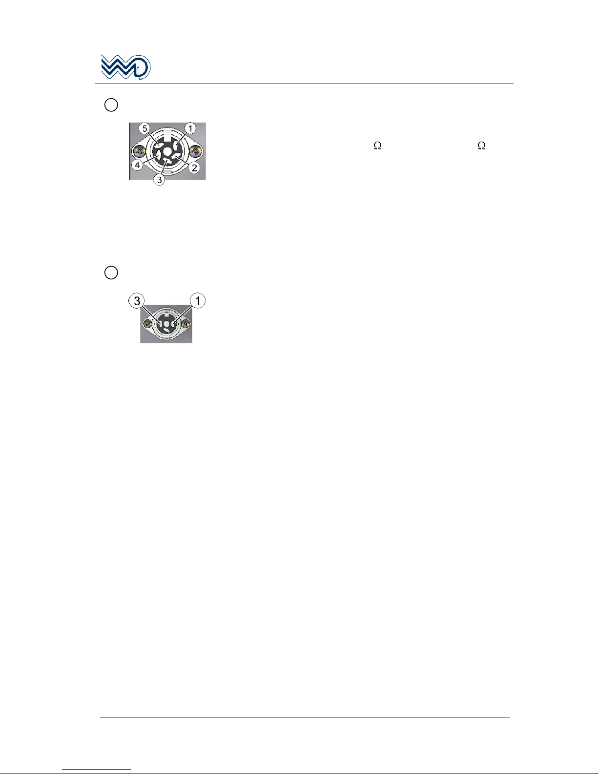
5-pole twist-lock DIN socket to connect microphone, headphone and
PTT-switch.
Mating DIN plug: article No. E08834
Any dynamic microphone (200 to 600 ), headphone (ca. 300 ),
push-to-talk key, or dynamic type head-set can be connected to this
socket. Wiring refer to "Carrying Case PS, Circuit Diagram".
Pin 1 Common Ground (PTT key/Headphone)
Pin 2 Dynamic microphone
Pin 3 Headphone
Pin 4 Microphone Ground
Pin 5 Push-to-talk key
14
NEW SOCKET!
External Supply
3-pole twist-lock DIN socket to charge the built-in battery or to supply
the radio by external 12 Vdc sources.
Mating DIN plug: article No. E61933
The capacity of the built-in battery may not be adequate due to
frequent transmitting operations or very long operating times without
possibility to recharge. Radio operation can be enabled through an
external 12 Vdc power source such as an automobile battery via our
Car Cable F10393 which fits into the cigarette lighter socket of most
cars (minus on common ground).
Pin 1 Plus 12 Vdc
Pin 3 Minus 12 Vdc (Ground)
Page 20
FSG 2T PS
Portable VHF/AM Airband Transceiver
20
DITTEL D10077 May 2010
3.3 Frequency Display
5-digit liquid crystal display (LCD), may be back-lit by pressing the
"Test" button 11.
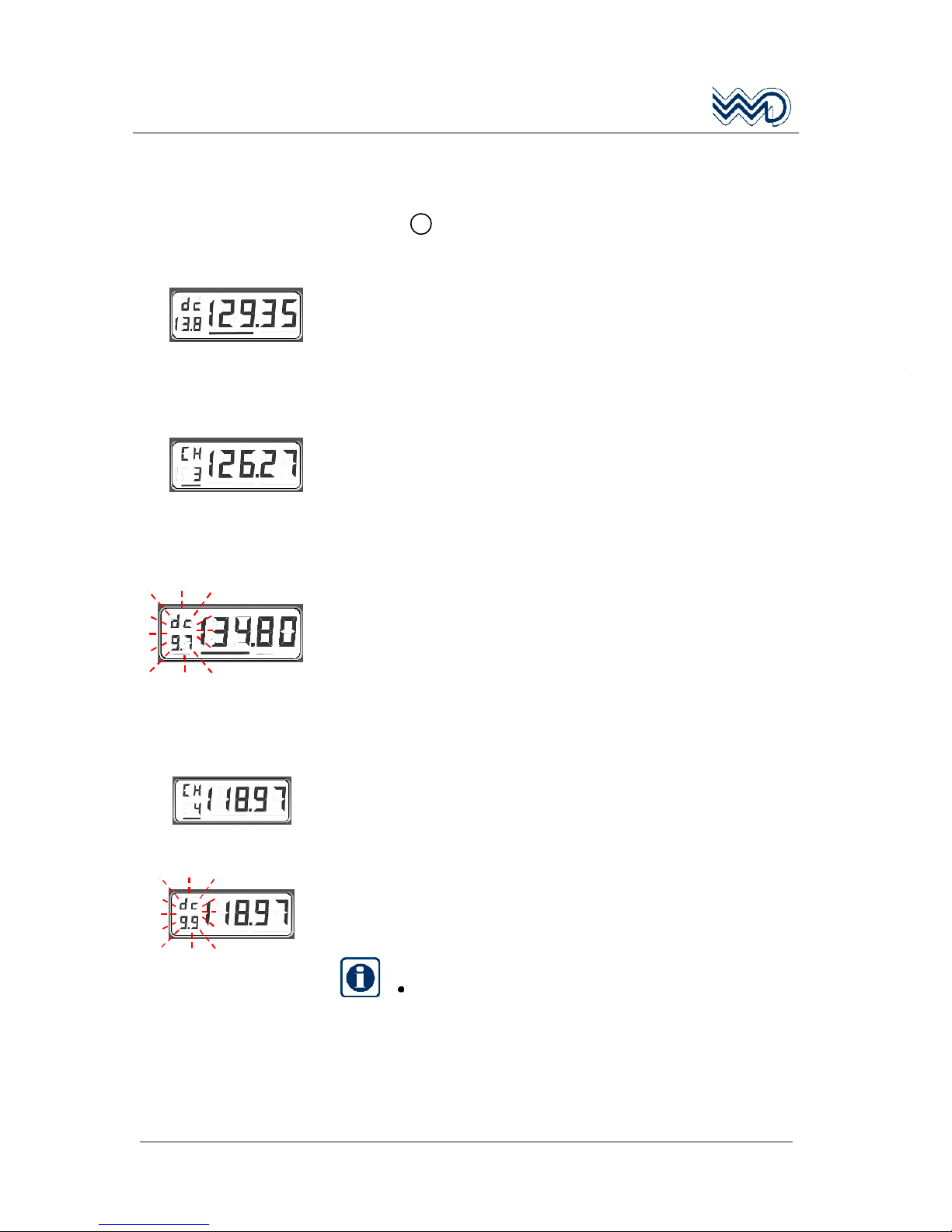
a) DIRECT TUNE MODE, Normal Operation:
Example:
Display shows an active frequency of 129.350 MHz. Turning the F/CH
knob will either increase or decrease the MHz-portion of the
frequency.
Normal on-board Supply 13.8 Vdc (11 16 Vdc).
b) CHANNEL MODE
, Normal Operation:
Example:
Display shows Channel no. 3 with its associated active frequency of
126.275 MHz. Turning the
F/CH knob will either increase or decrease
the Channel number.
c) DIRECT TUNE MODE (continuously flashing Dc value, Emergency
Operation):
Example:
Display shows an active frequency of 134.800 MHz. Turning the F/CH
knob will either increase or decrease the MHz-portion of the
frequency.
Low-voltage: 9.7 Vdc (indicator is flashing!)
d) CHANNEL MODE, Emergency Operation:
Example:
Display shows Channel No. 4 with an active frequency of
118.975 MHz.
Low-voltage: 9.9 Vdc, indicator is flashing!
The flashing low-voltage warning is shown automatically every 25 s
for 5 seconds when the supply is between 9 Vdc and 11 Vdc.
Steady display for
25 seconds:
Flashing supply indicator
for 5 seconds:
IMPORTANT!
During Emergency Operation (low voltage) no
storing of frequency is possible!
Page 21
FSG 2T PS
Portable VHF/AM Airband Transceiver
May 2010 DITTEL D10077
21
3.4 Error Codes
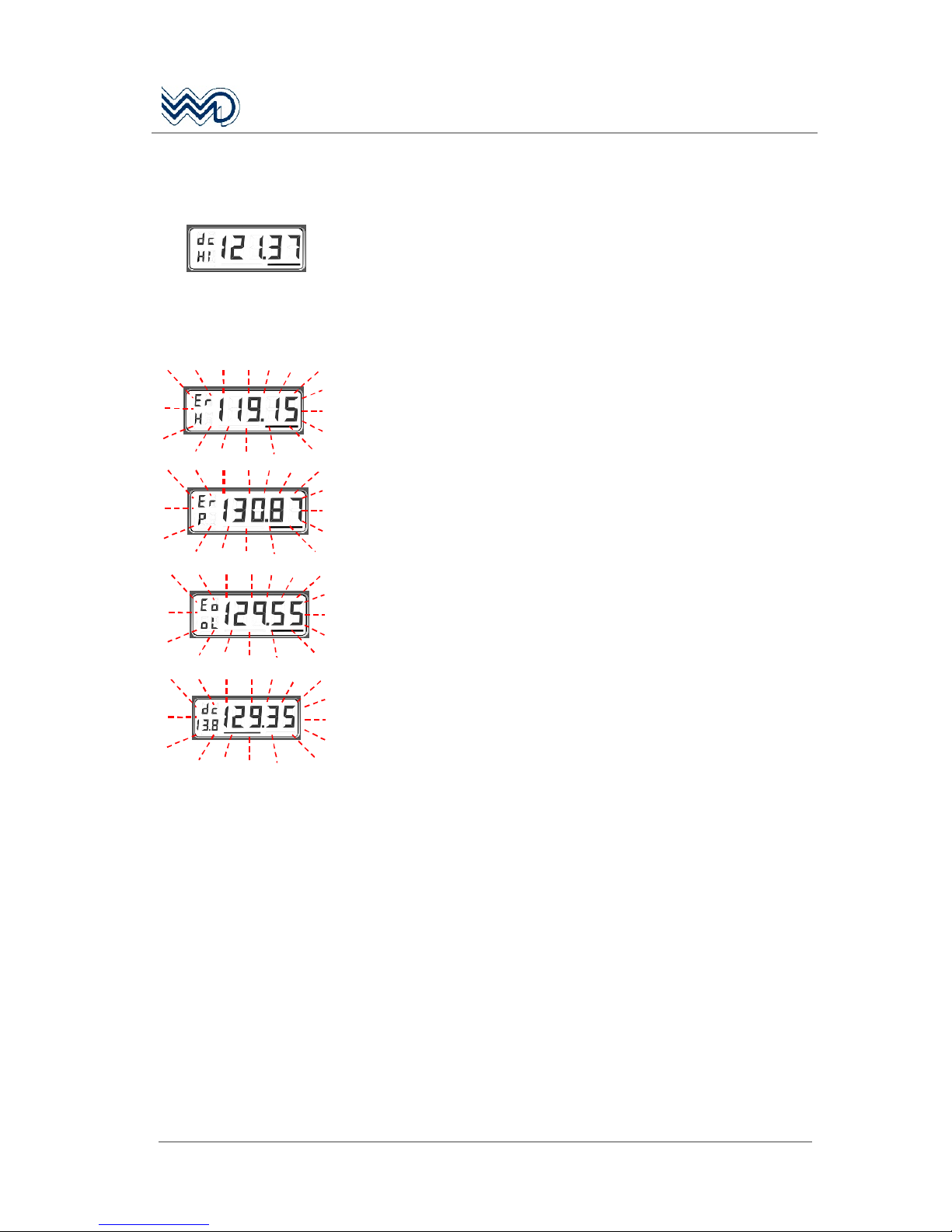
Display in all Modes!
High Voltage: Continuously slightly too high supply voltage changes
value indication into HI (above 16.1 Vdc / below 16.5 Vdc).
Above approximately 16.5 Vdc, the radio automatically switches OFF
itself, at no display indication.
When supply is reduced to between 16 Vdc and 10.5 Vdc, the FSG 2T
comes back into operation.
Temperature Error: The whole LC display flashes. Temperature of
the Transmitter Power Amplifier is too high. The keyed transmitter will
be disabled.
Switch OFF the radio, wait a few seconds and switch ON again.
Process Error: The whole LC display flashes. A severe process error
must have occurred.
Try to revive the radio by switching OFF and ON again.
If the same error occurs contact a DITTEL approved repair facility!
Out-Of-Lock Error: The whole LC display flashes. A severe
frequency error must have occurred.
Try to revive the radio by switching OFF and ON again.
If the same error occurs contact a DITTEL approved repair facility!
2 Minutes TOT Time-Out-Timer: After two minutes continuous
transmitting the transmitter of the FSG 2T switches OFF itself and the
whole LC display flashes as long as the PTT key is pressed.
When the PTT key stuck accidentally it can be received with the
adjusted frequency although the display is flashing. After switching
the radio OFF and ON again it can be transmitted for another 2
minutes followed by receive mode.
Page 22

FSG 2T PS
Portable VHF/AM Airband Transceiver
22
DITTEL D10077 May 2010
Page 23
FSG 2T PS
Portable VHF/AM Airband Transceiver
May 2010 DITTEL D10077
23
4 Operation
4.1 Introduction
This section contains a description of the basic operation procedure
for the portable transceiver FSG 2T PS.
DANGER!
DO NOT OPERATE THIS RADIO IN AN EXPLOSIVE
ATMOSPHERE (PETROLEUM FUELS, SOLVENTS, DUST,
ETC.).
A front view of the FSG 2T PS is given on the last page of this manual.
Please fold out the back flap when reading the operation instructions.
4.2 Battery Check
If applicable, disconnect battery charger from External Supply
Socket 14, before checking the battery supply.
Press the red test button of the battery indicator 11.
The LED indicators
11
will light up.
5 LEDs ON = battery fully charged, supply OK!
3 to 4 LEDs ON = battery partially discharged; reduced
operation time when powered only from
the battery.
2 or less LEDs ON = battery discharged. The battery should
be recharged or the radio should be
powered by an external 12 Vdc source
of adequate capacity (e.g. automobile
battery).
Additionally the transceiver FSG 2T includes a 3 digit display of the
actual supply voltage level while in the DIRECT TUNE MODE. At dc
levels below 11 V the voltage digit value starts automatically flashing
for low supply warning!
Page 24

FSG 2T PS
Portable VHF/AM Airband Transceiver
24
DITTEL D10077 May 2010
Reference: Approximately +20°C / +68°F, battery
7.2 Ah, only radio is supplied.
Duty cycle:
10% Transmit, 20% Receive, 70% STBY
Flashing Dc value only
in Transmit:
ca. 4 hrs left
Flashing Dc value also
during Receive:
ca. 45 min. left.
Recommendation: Reduce utmost
transmitting!
Short-time flashing Dc
value during Standby
(SQ ON, clear channel)
ca. 45 min. left in Standby.
Cease transmitting!
Continuous flashing Dc
value during Standby
(SQ ON, clear channel)
Radio will soon switch OFF itself! Recharge
battery as soon as possible.
IMPORTANT!
These transitions are fluent. Recovery effect after load reduction
may be possible. Low battery temperature reduces operation time.
The battery must always be recharged immediately after an
extensive discharge because this incurs the risk of deterioration
and permanent damage - this risk is increased if a discharged
battery is stored in that state.
Page 25
FSG 2T PS
Portable VHF/AM Airband Transceiver
May 2010 DITTEL D10077
25
4.3 Battery Charging
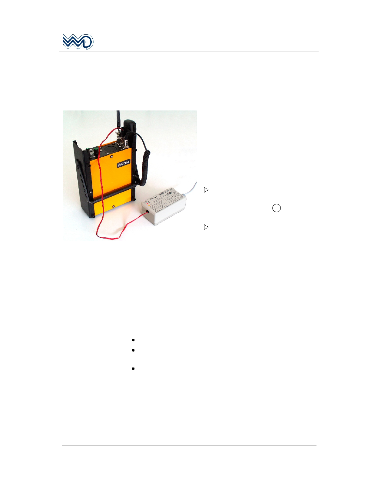
To recharge the built-in 7.2 Ah accumulator we recommend our
automatic battery charger DL-50A.
Charging should be done within the ambient temperature range of
+10°C to +40°C.
The charger DL-50A is designed for
connecting to 115 Vac or 230 Vac, 50 to
60 Hz mains. For operation, check that
the unit's operating voltage is identical
with your local mains supply. If required,
set the voltage selector switch by means
of a suitable tool to the respective voltage,
changing of the fuses is not required
(DL-50A is factory pre-set to 230 Vac).
For charging the internal battery
connect charger cable of DL-50A to
the 3-pole DIN socket 14 of carrying
case PS.
Plug the mains cable into a suitable
wall outlet. The red pilot lamp
(POWER) lights up.
Charging - yellow
pilot lamp lights
Charging lasts up to 30 hours depending on the state of the battery
(for 7.2 Ah battery). When the switch-off voltage is reached the
charger switches automatically to trickle charge. The capacity at the
end of charging is about 90% of the full rated capacity.
Trickle charge -
yellow pilot lamp
goes off
The built-in lead acid battery is now continuously charged on low
current. The full capacity of the battery is thus guaranteed.
Overcharging the battery is not possible due to automatic controlled
charging function, even if the trickle charge is maintained over a long
period.
The transceiver may be operated while charging.
For trickle charging or buffer operation the charger can be left
unattended continuously connected to mains.
A fully charged battery can be stored for several months.
Page 26
FSG 2T PS
Portable VHF/AM Airband Transceiver
26
DITTEL D10077 May 2010
4.4 Antenna - Antenna jack SO 239
DANGER!
NEVER TRANSMIT in closed vehicles, aircraft or inside
buildings with the spring steel band antenna! This may cause
malfunction of the avionics, trigger the airbag or mix-up
electronic equipment! Always operate the radio with a
suitable external antenna!
NEVER OPERATE the radio without any antenna!
Already a transmit power higher than 1 Watt creates very high
electromagnetic field strengths in close proximity to
shortened antennas (e.g. rubber helix antennas). This causes
a high radiation exposure for persons and may produce
sparks under certain circumstances!
IMPORTANT!
A good antenna is the best RF amplifier!
Your radio is only good as the antenna!
As portable radio used in the open the FSG 2T PS is usually operated
with the spring steel band antenna (Article-No. F10345).
The spring steel band antenna, connected to the SO 239 antenna
jack 10, can be replaced by any other 50 antenna with UHF type
PL-259 cable plug and a frequency range of 118 137 MHz
minimum.
When the FSG 2T PS is operated in open, non-metallic or wire mesh
balloon baskets we recommend our Balloon Antenna BFA 1.
To operate the radio in aircraft or ground vehicles a suitable external
antenna should always be used.
For long range operation a base station folded top antenna, grounded
for lightning protection, is recommended.
Ensure the plug of your antenna or antenna cable is securely
tightened.
If the spring steel band antenna is used, adjust it in a vertical
position by tightening the screwed cap and wing screw.
4.5 Microphone Socket
The hand-held dynamic microphone with push-to-talk switch (ArticleNo. F10346) can be replaced by any other dynamic microphone (200
to 600 Ohms) with PTT switch or a head-set for dynamic type
systems with additional PTT switch (mating 5-pole DIN plug: ArticleNo. E08834, wiring to station, refer to Circuit Diagram PS).
Plug microphone, ensure the plug is secured by twist-lock cap.
Page 27
FSG 2T PS
Portable VHF/AM Airband Transceiver
May 2010 DITTEL D10077
27
4.6 Turning ON - Selecting Frequency - Audio Volume
CAUTION!
The FSG 2T PS should be turned ON after engine start-up. This
is a simple precaution which helps to protect the solid state
circuitry and extends the operating life of your avionics
equipment.
IMPORTANT!
Frequent transmissions as well as large receiving volume
reduce the operating time when radio is only powered by the
built-in battery!
Turn the radio FSG 2T ON by rotating the VOL knob 1 clockwise.
For a short time the TX/RX LED 4 lights up green and all
segments of the display are visible to verify their operation. After
indicating the Firmware version, the last used operating mode and
frequency are displayed.
No warm-up period is required. However, at temperatures of approx.
-20°C / -4°F, the LC display needs approximately one second until it
is fully visible when the frequency or operating mode is changed.
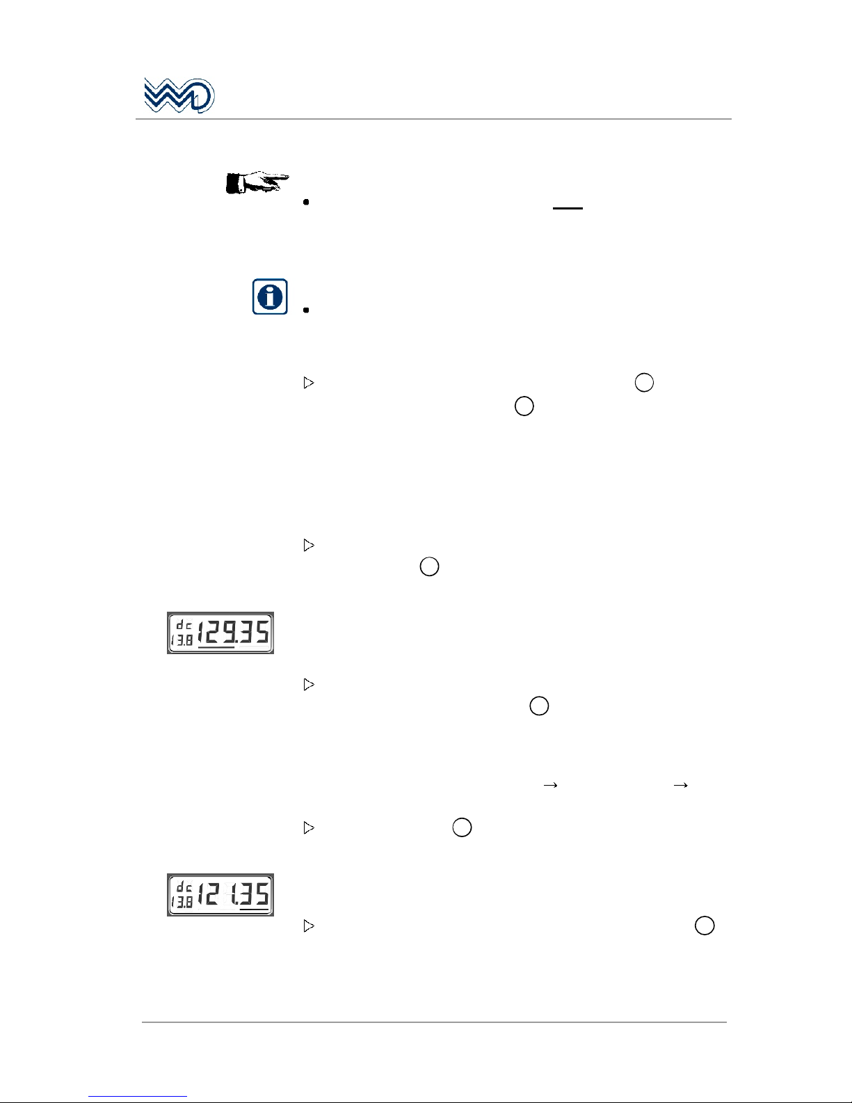
To change the operating mode and therefore the display: Press
the F/CH button 5.
Example:
STANDARD: DIRECT TUNE MODE
After switching ON the radio, either the MHz portion or the kHz
portion of the displayed frequency is underscored. The underscore
indicates accessibility to this portion.
Assume the MHz is underscored: Select the appropriate MHz
portion by rotating the F/CH knob 6. A clockwise rotation will
increment the previous frequency in 1 MHz steps (130, 131, 132
etc.) while a counter-clockwise rotation will decrement the
previous frequency in 1 MHz steps (128, 127, 126 etc.) with
rollover at each band edge (118.XX 136.XX or 136.XX
118.XX).
Press the F/CH knob 6 once, the cursor will jump to underscore
the kHz portion.
The underscored kHz portion of the frequency indicates accessibility
to kHz selection.
Select the appropriate kHz portion by rotating the F/CH knob 6.
A clockwise rotation will increment the previous frequency in
25 kHz steps (37, 40, 42 etc.) while a counter-clockwise rotation
will decrement the previous frequency in 25 kHz steps (32, 30, 27
Page 28

FSG 2T PS
Portable VHF/AM Airband Transceiver
28
DITTEL D10077 May 2010
etc.) with rollover at each MHz and band edge (121.97 122.00
or 121.00 121.97).
This is the new active frequency!
Example:
CHANNEL MODE or CH ONLY:
Important:
The appropriate operating frequency must be stored
already in a memory channel (refer to § 4.9 Memory
Programming).
Select appropriate channel memory number together with the
associated frequency by rotating the F/CH knob 6. A clockwise
rotation will increment (4, 5, 6 etc.) while a counter-clockwise
rotation will decrement (2, 1, 20 etc.) the previous channel
number with rollover at each edge.
This is the new active frequency and its associated channel memory
number!
Rotate VOL knob clockwise, about half way.
Continue with either
4.7 Receive (Listen) Operation, or
4.8 Transmit (Talk) Operation
4.9 Memory Programming
Page 29

FSG 2T PS
Portable VHF/AM Airband Transceiver
May 2010 DITTEL D10077
29
4.7 Receive (Listen) Operation
After turning the radio ON the automatic squelch is either ON or
OFF depending on SQ knob 2 position.
Squelch ON means that without received signal the receiver
noise is blocked, the TX/RX LED 4 is clear. When normal signals
are received, the TX/RX LED 4 turns to green; weak signals and
interfering pulses are disabled.
Set the RX volume of the built-in loudspeaker 9 or earphone to
a comfortable level by rotating the VOL knob 1.
Weak signals can be received if the squelch circuit is switched
OFF by rotating the SQ knob 2 fully counter-clockwise. Then
typical RX noise is continuously heard during communication
breaks.
Rotating the SQ knob 2 more clockwise switches the squelch
circuit ON again.
DO NOT press the PTT (Push-To-Talk) key if you want to receive!
During RX the TX/RX LED 4 must not light RED or flicker
YELLOW!
This radio contains an audio-leveling circuit. So if you change the
frequency or you receive another station you should get an almost
constant audio volume (the received signal must be at least
modulated by 30% AM).
IMPORTANT!
Switching OFF the Squelch only makes sense if long range
reception shall take place. Thus the radio is noisy during
Standby operation, but no weak signals are suppressed and
the full receiving range is available!
Notice increased current consumption when battery operated!
Page 30
FSG 2T PS
Portable VHF/AM Airband Transceiver
30
DITTEL D10077 May 2010
4.8 Transmit (Talk) Operation
WARNING!
Every radio, when transmitting, radiates energy into the
atmosphere, therefore:
DO NOT operate this portable radio in an explosive
atmosphere (petroleum fuels, solvents, dust, etc.)! Risk due to
generation of sparks!
DO NOT transmit with the spring steel band antenna inside
aircraft or vehicle. This may cause malfunction of onboard
avionics, trigger the vehicle airbag or interfere onboard
instruments! Always operate the portable radio FSG 2T PS with
a suitable outdoor / external antenna! Assure appropriate
lightning protection / grounding where (elevated) outdoor
antennas are used.
Never place the radio such as the antenna gets very close to,
or touching, exposed parts of the body, especially the face,
shoulder or the eyes. Persons with pacemakers should be
aware that proper functioning may be affected when in the
vicinity of the antenna!
IMPORTANT!
Please keep radio discipline!
DO NOT transmit on a busy channel!
DO NOT transmit on
121.50
MHz as this is the international civilian
aircraft emergency frequency!
Care for an all-round obstacle free antenna location; the called
station should be within "line-of-sight" distance.
If the operating mode
shall be changed:
Push the F/CH button 5.
If the active frequency
shall be changed: Refer to § 4.6 Turning ON - Selecting Frequency - Audio
Volume.
Transmitting is normally performed on a clear channel (no
communication audible).
Take the microphone and hold it near to your lips (1 to 2). Press
and hold the PTT (Push-To-Talk) key. Talk in a loud, clear voice
into the microphone opening. Make each transmission as brief as
possible. As long as the PTT key is pressed the TX/RX LED 4 at
the front lights red! When the radio is modulated properly, the red
TX/RX LED turns to flickering YELLOW.
Release the PTT key to end transmission and to clear the channel
for reception; the TX/RX LED must turn to clear (Standby) or green
(Receive).
Page 31
FSG 2T PS
Portable VHF/AM Airband Transceiver
May 2010 DITTEL D10077
31
IMPORTANT!
The radio is equipped with a transmit TOT time out timer. This is
used to limit the duration of transmissions to approximately 2
minutes. When the transmitter is keyed continuously longer than 2
minutes the display of the FSG 2T starts flashing and transmission
is disabled. Although the display is flashing receiving on the
displayed frequency is possible!
If you have to make calls longer than 2 minutes, momentarily
release the PTT key and press again.
Should the TOT disable the transmitter accidentally (e.g. stuck
PTT key) and you have to transmit, turn radio OFF and ON
again. This allows another 2 minutes to transmit.
Page 32
FSG 2T PS
Portable VHF/AM Airband Transceiver
32
DITTEL D10077 May 2010
4.9 Memory Programming
IMPORTANT!
Memory programming is disabled for all FSG 2T radios which
are marked CH ONLY!
Memory programming is disabled at a supply voltage below
11 Vdc.
When storing a frequency into a memory the "old" frequency
will be overwritten without warning!
Up to 20 non-volatile memories can be user-programmed. They are
accessible after calling up the respective CHANNEL MODE.
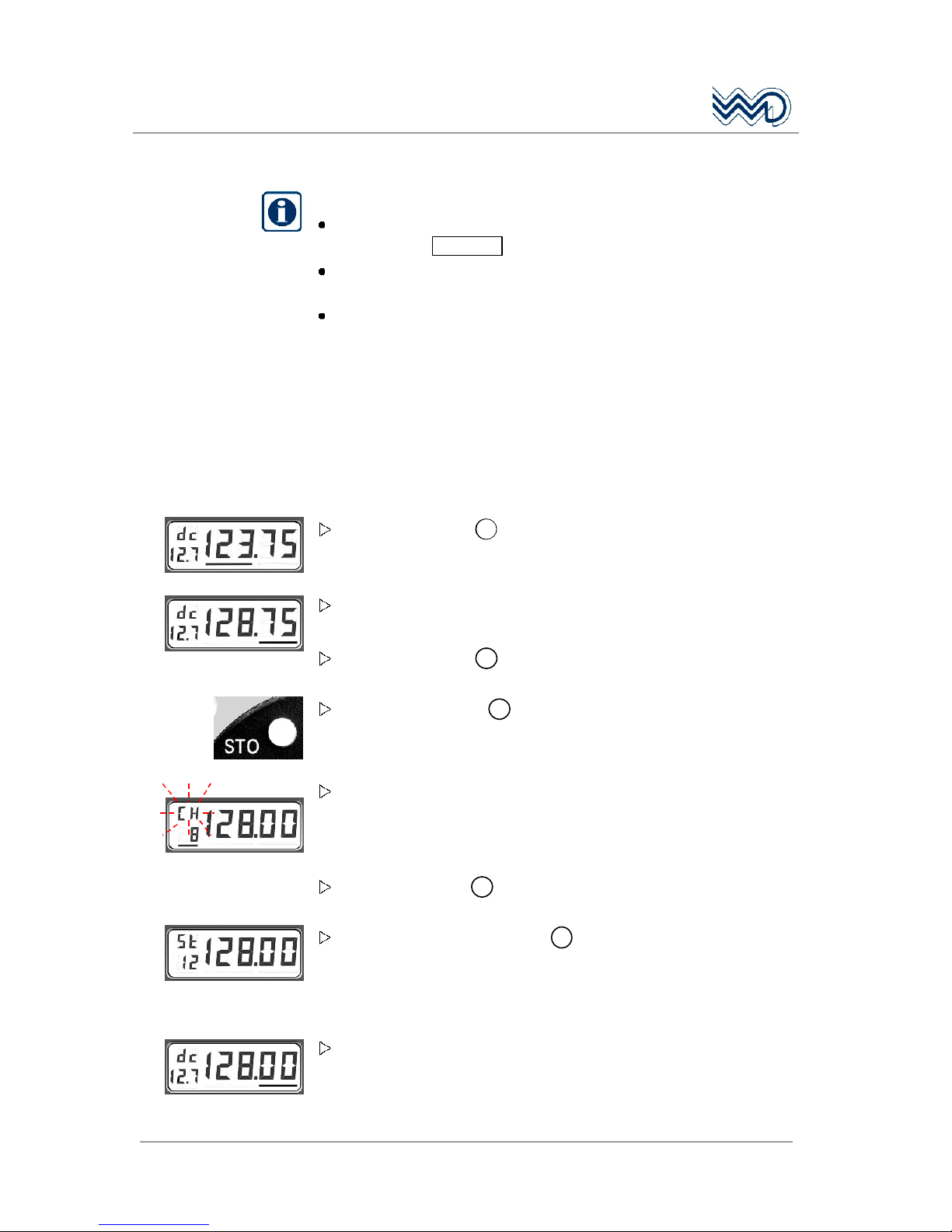
4.9.1 Programming while in the DIRECT TUNE MODE:
Example:
Turn the F/CH knob 6 to change the underscored portion of the
frequency to the desired frequency.
Press the same knob once and note that the cursor has jumped to
underscore the other portion of the frequency.
Turn the F/CH knob 6 to select the desired frequency.
Press the STO button 3 to initialize storing.
Release the STO button. The "dc" display disappears, a flashing
"CH" together with the underscored last used channel number is
shown. The active frequency is now ready within 1 minute to be
stored in any of the 20 memory channels.
Use the F/CH knob 6 to select the desired memory location.
Press and hold the STO button 3 for at least 1 second. The
flashing "CH" should change to steady "St" and the underscore
disappears indicating that it has been stored into memory
successfully.
Release the STO button and the radio returns to DIRECT TUNE
MODE. The stored frequency is now the active frequency.
Page 33
FSG 2T PS
Portable VHF/AM Airband Transceiver
May 2010 DITTEL D10077
33
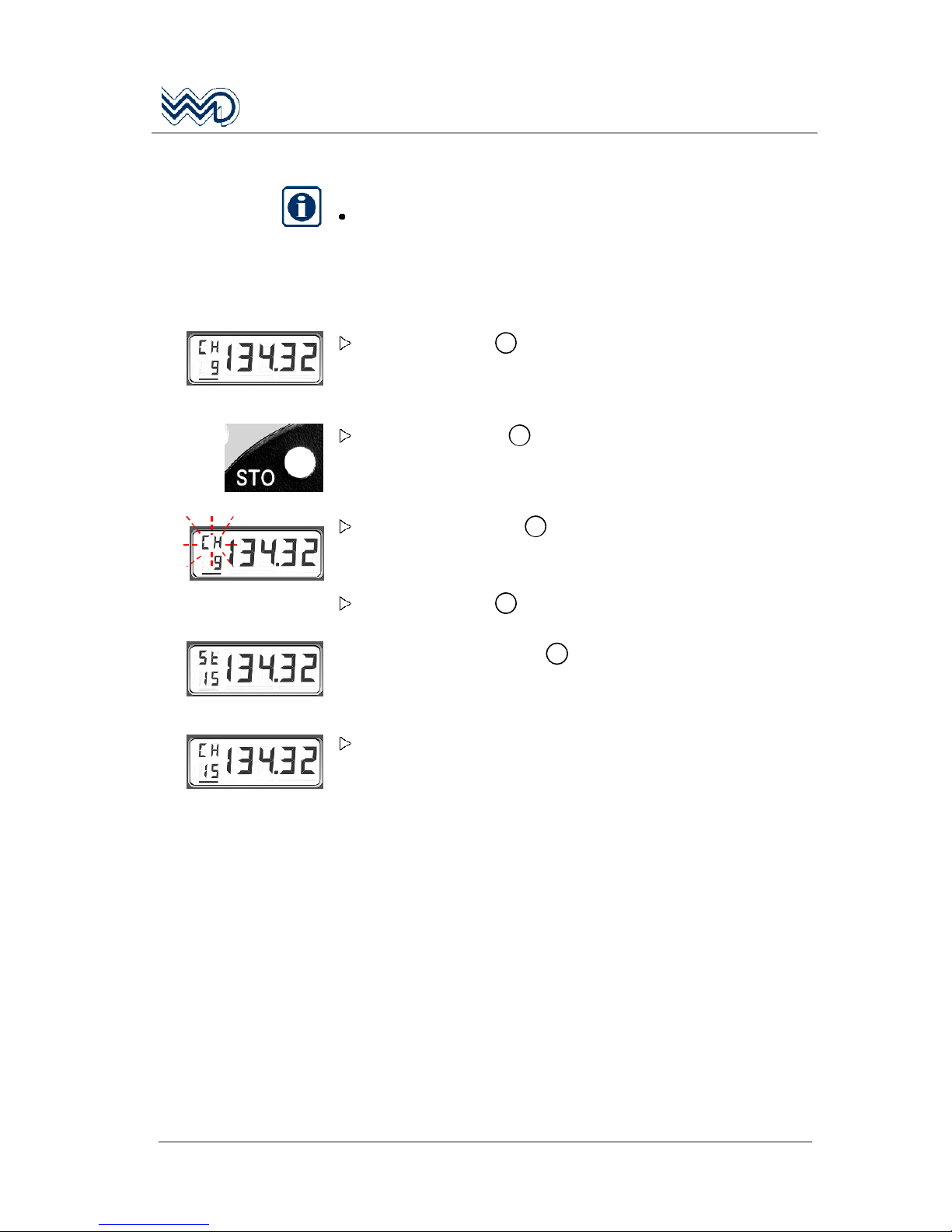
4.9.2 Programming while in the CHANNEL MODE:
IMPORTANT!
While in the CHANNEL MODE only pre-programmed Channel
Numbers with its corresponding frequencies can be stored in
other memory locations!
Example:
Turn the F/CH knob 6 to change the underscored Channel
Number to the desired Channel Number to be stored in another
memory location.
Press the STO button 3 once to initialize storing.
Release the STO button 3. A flashing "CH" is shown. The active
Channel Number and its frequency is now ready within 1 minute
to be stored in any of the other 19 memory channels.
Turn the F/CH knob 6 to select the desired memory location.
Press and hold the STO button
3
for at least 1 second. The flashing
"CH" should change to steady "St" and the underscore disappears
indicating that it has been stored into the new memory successfully.
Release the STO button and the radio returns to CHANNEL MODE.
The stored Channel Number is now the active Channel Number
with its corresponding frequency.
Page 34

FSG 2T PS
Portable VHF/AM Airband Transceiver
34
DITTEL D10077 May 2010
4.10 Lighting the Frequency Display and Front Panel
Lighting of the frequency display 7 and front panel is activated
by pressing the red test button of the battery indicator 11.
4.11 Turning OFF the radio
Always turn OFF the radio after use by rotating the VOL switch 1
to the fully ccw position to prevent unnecessary discharge of the
battery. During standby or carrying, the handheld microphone
(A/N F10346) can be hung onto the right flange of the case.
4.12 External Power Supply
The capacity of the built-in battery may not be adequate due to
frequent transmitting operations or very long operating times without
possibility to recharge. Radio operation can be enabled through an
external 12 Vdc power source such as an automobile battery via our
Car Cable F10393 which fits into the cigarette lighter socket of most
cars (minus on common ground).
4.13 Removing & Installing the Transceiver
IMPORTANT!
Switch OFF the radio first! This is a simple precaution which
helps protect the solid state circuitry and extends the
operating life of your avionics equipment.
To dismount the transceiver FSG 2T from the Carrying Case PS,
remove the two cross-recessed screws 8 and lift off the
matching plate. Carefully pull out the transceiver together with the
adapter plate, wire harness and antenna cable. Open sliding lock
of 15-pole receptacle, unplug wire harness and antenna plug.
To install the transceiver, carefully pull out the wire harness of the
case, connect the 15-pole receptacle and secure it by the sliding
lock. Plug antenna cable and secure it by twisting the BNC plug.
Slowly insert transceiver into the case. Put on the matching plate
and fix it by the two cross-recessed screws 8. Check fixing and
function.
Page 35
FSG 2T PS
Portable VHF/AM Airband Transceiver
May 2010 DITTEL D10077
35
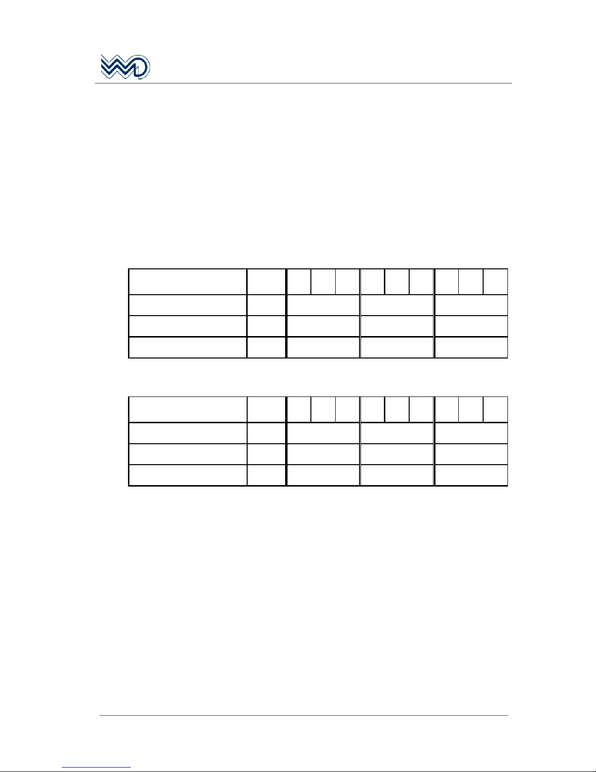
4.14 Battery Operating Times
The following duty cycle of Transmit (TX), Receive (RX) and Standby
(STBY) results in available operating time (hours). Both the worst and
the most favorable operation conditions are considered, e.g.
maximum receiver volume combined with maximum speaker load.
Higher current consumption will degrade the nominally available
battery capability, as well as lower temperatures. The following tables
show significant time differences depending on current consumption
due to different duty cycles and temperatures.
Condition: only headset operated
Max. current drain
.05A 1.35A .26A .05A 1.35A .26A .05A 1.35A .26A .05A
Sealed lead-acid battery
12 Volts 7.2 Ah
STBY,
w/out RX
5%
TX 5%RX
90%
STBY
10%
TX
20%
RX
70%
STBY
20%
TX
40%
RX
40%
STBY
Temperature -20°C/-4°F 76 hrs 30 hrs 16 hrs 9 hrs
Temperature +20°C/+68°F 131 hrs 52 hrs 29 hrs 16 hrs
Temperature +50°C/+122°F 139 hrs 55 hrs 30 hrs 16 hrs
Condition: maximum RX audio volume (Loudspeaker
Max. current drain
.05A 1.35A .8A .05A 1.35A .8A .05A 1.35A .8A .05A
Sealed lead-acid battery
12 Volts 7.2 Ah
STBY,
w/out RX
5%
TX 5%RX
90%
STBY
10%
TX
20%
RX
70%
STBY
20%
TX
40%
RX
40%
STBY
Temperature -20°C/-4°F 76 hrs 25 hrs 11 hrs 6 hrs
Temperature +20°C/+68°F 131 hrs 44 hrs 20 hrs 10.5 hrs
Temperature +50°C/+122°F 139 hrs 46 hrs 21 hrs 11 hrs
4.15 Emergency Operation
Without degradation the FSG 2T can be operated on a dc source
between 11 Vdc and nearly 9 Volts. This however will NOT reduce
the TX output level, RX sensitivity, and audio output power, due to
internal supply regulation. Below 11 Volts the dc indicator flashes
continuously as a low supply warning.
Since the current drawn from battery will increase with lowered Dc
supply voltage, the automatic shut-down will speed-up.
If the supply voltage drops below 9 Vdc the FSG 2T switches OFF
itself. This automatic feature avoids battery damage due to deep
discharging, even if the radio is left switched ON for months! This is
true for all types of 12 Vdc batteries.
If the battery recovers and voltage exceeds approximately 10.5 Vdc,
the radio returns to operation with the last used setting.
Page 36
FSG 2T PS
Portable VHF/AM Airband Transceiver
36
DITTEL D10077 May 2010
4.16 Siting
The portable radio FSG 2T PS operates in the VHF frequency band,
this is a Line-Of-Sight (LOS) frequency; therefore, siting of the radio
greatly affects its operating range. The longest range is normally
obtained when a direct LOS is maintained between the radios. Use of
hilltop, roof or tower locations will increase the LOS range. Location in
valleys with intervening hills, behind vehicles or buildings or in dense
woods may reduce or prevent communications. If possible, avoid
antenna locations near electrical interference sources, such as
computers, power and telephone lines, radar, welders and electrical
generators.
4.17 Base Operation
To operate the radio as a base station, a weather-proof anti static and
lightning protected folded-top antenna is ideally suited. The antenna
should be mounted vertically and elevated as high as possible on a
roof, horizontally free of obstacles. The antenna mast has to be
grounded and anchored, as necessary. For a distance of up to 15
meters the antenna cable may be a RG-58 C/U type, for longer
distances always use the cable type RG-213/U (low loss).
In general, the antenna cable should not be longer than necessary.
4.18 Troubleshooting
If the portable transceiver FSG 2T PS does not operate correctly,
check the following:
Is the required frequency visible? Adjust required frequency or
channel number!
Is battery supply sufficient? Observe supply indicator particularly
during transmit, at least 11 Vdc must be shown!
Weak RX signal? Adjust SQ control counter-clockwise!
Weak TX signal? Check microphone, MIC setting, radio, or
antenna system! Lights TX/RX LED RED while speaking? The voice
volume is too low, check MIC setting. Speak loud and clear while
the lips are facing the microphone! The TX/RX LED must flicker
YELLOW!
Singing during transmit? Adjust sidetone more quietly; keep
microphone in other position!
Rattles when transmitting? Metal propellers between antenna and
ground station!
Tower hears carrier, but no voice? Check TX/RX
LED (red or
Page 37

FSG 2T PS
Portable VHF/AM Airband Transceiver
May 2010 DITTEL D10077
37
yellow?), microphone and contacts on microphone jack!
Noisy - distorted - garbled? Suppress electrical interference of
motor aircraft or vehicle (generator, regulator), check antenna-,
microphone- and radio- connector for proper seat!
Flashing display, transmitter switches off itself? PTT key sticks!
Check PTT key and cables. Transmitter was keyed longer than 2
minutes. Release PTT key, normal operating is possible again. In
case of emergency turn radio OFF and switch ON again, this
permits another two minutes to transmit "blind".
In case of doubt, compare operation of the transceiver with another
transceiver on the same location or call another station. If service is
necessary please consult your authorized dealer or an approved
avionics workshop.
Page 38

FSG 2T PS
Portable VHF/AM Airband Transceiver
38
DITTEL D10077 May 2010
Page 39

FSG 2T PS
Portable VHF/AM Airband Transceiver
May 2010 DITTEL D10077
39
5 Technical Data FSG 2T PS
5.1 General
Type:
FSG 2T PS
Portable amplitude modulated (AM) VHF Avionics Transceiver
Frequenc y range: 118.000 136.975 M Hz
Channels: 760 channels, 25 kHz spacing
Frequency selection: VFO, digital
Frequency display: 5 digit 7-segment LCD display (backlit)
Frequency control: PLL frequency synthesizer, microprocessor controlled
Memories 20, stored in a non-volatile EPROM
Additional features: 2 operating modes; voice activated Intercom; transmit Sidetone
via headphone; onboard supply display; three-color status LED;
TX Time-out-Timer; error code.
Connectivity for
External 12 Vdc supply, dynamic, non-amplified microphone,
PTT key, headphone, headset, 50 Ohm antenna
5.2 Dimensions, Weight
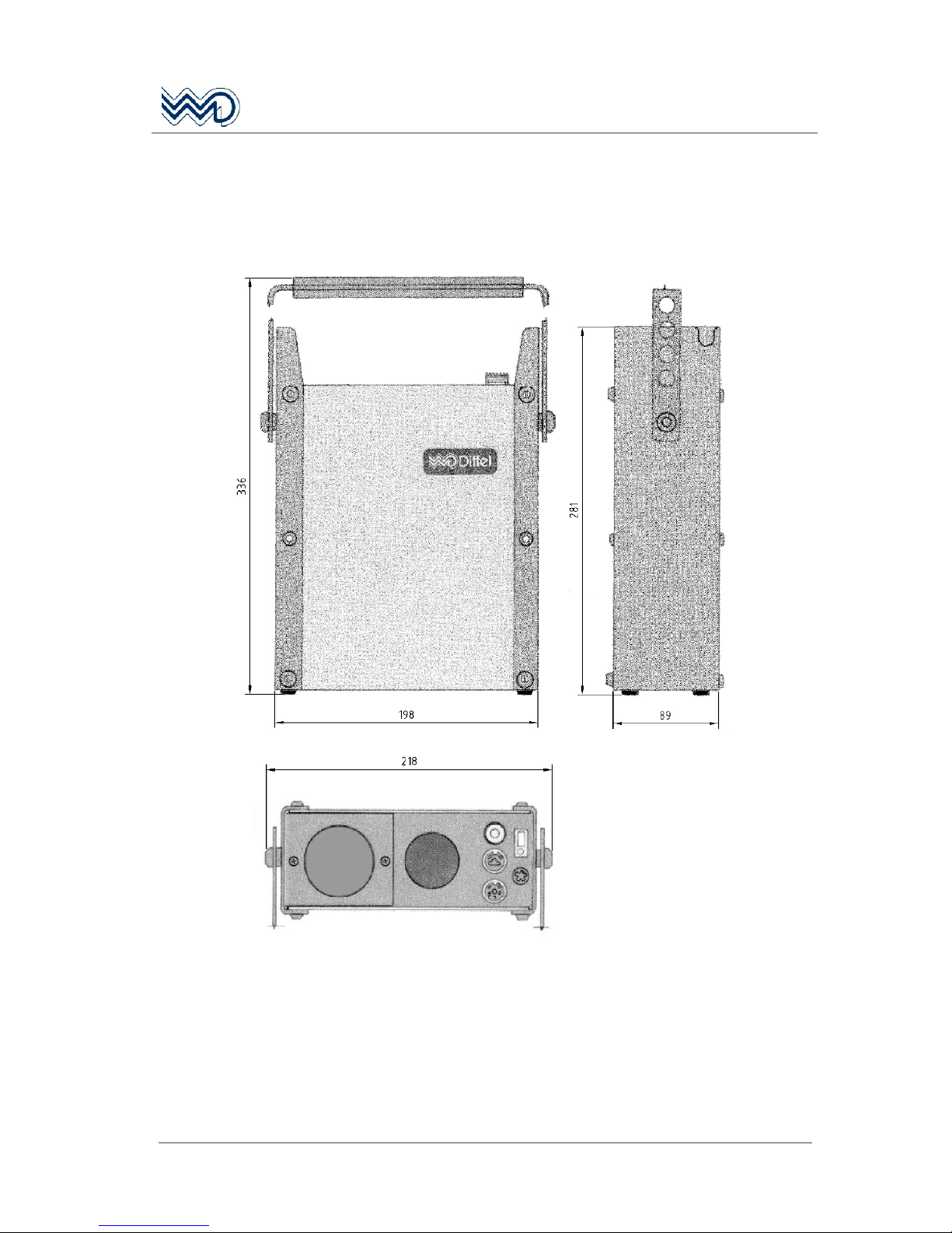
Dimensions Width = 89 mm, height = 336 mm, length = 218 mm (including
handle)
Weight
ca. 5.0 kg including hand-held microphone and spring steel band
antenna
5.3 Power Supply, Fuses
Built-in battery Valve-regulated lead acid battery, 12 Vdc / nominal 7.2 Ah
Voltage Ra nge, Radio Nominal 1 3.8 Vdc ( normal 11.0 16.1 Vdc)
Emergency Operation 9 Vdc 11 Vdc (flashing display), n o performance degradation
Automat ic Turn-OFF At approx. 8.5 9 Vdc, co mes back at approx. 10.5 Vdc
Current Consumption at: 9 Vdc 11 Vdc 13.8 Vdc 16 Vdc
Squelch ON, no AF volume 80 mA 65 mA 50 mA 40 mA
Receive, Headphone
400 mA 330 mA 260 mA 210 mA
Receive, max. volume,
Loudspeake r (30% 85% AM)
1,400 mA 1,150 mA 800 mA 600 mA
Transmit Mode (carrier /70% AM) 1.8 A 2.2 A 1.45 A 1.7 A 1.1 A 1.35 A 0.9 A 1.2 A
Backlighting add 60 mA
Dc supply voltage metering
status
12.7 Vdc Battery full
12.0 Vdc Battery ca. ½ capacity
Emergency operation < 11.0 Vdc Battery is nearly flat, display starts flashing
between 11 V and 9 Vdc supply
Fuse, Carrying Case 1 × 6.3 Amp, medium time lag
Page 40

FSG 2T PS
Portable VHF/AM Airband Transceiver
40
DITTEL D10077 May 2010
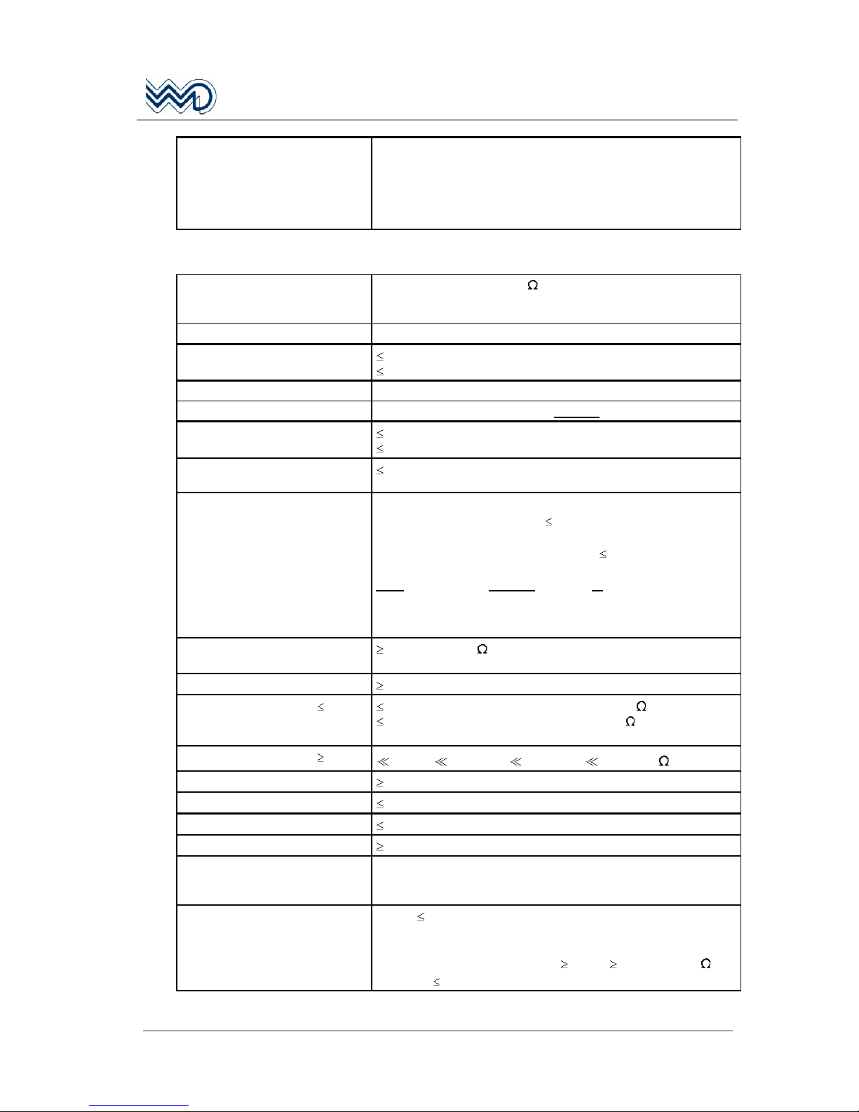
5.4 Detailed Receiver Specification
Receiver Type Single Superhet
IF Frequency IF 21.4 MHz, high injection
Sensitivity (m = 30% / 1,000 Hz)
1 µV ( -107 dBm / 50 ) for 6 dB S+N/N
Selectivity (AGC method)
6 dB at ± 8 kHz
60 dB at ± 17 kHz
70 dB at ± 25 kHz
Squelch Type, manual override Automatic (FM noise /Carrier override), adjustable on front panel
AGC (m = 30% / 1 kHz)
6 dB, 1 µV (-107 dBm) to 1 V (+13 dBm / 50 )
AGC Delay (RX), m = 30%/1 kHz
0.2 sec, 5 mV (-33 dBm) to 5 µV (-93 dBm / 50 )
AGC Recovery after TX
0.1 sec at 5 µV (-93 dBm / 50 ), after TX end
Transfer time RX to TX
50 msec
Modulation distortion
10%, 350 3,400 Hz (m = 85%)
Audio Frequency Response / AF
Fidelity
6 dB (+2 dB / -4 dB), 350 ... 3,400 Hz,
-20 dB at 4 kHz, 25 kHz Ch spacing (Climax Offset Operation)
Nominal AF Output (Speaker)
4 Watt into 4 (at 9 Vdc 16.1 Vdc supply)
Nominal AF Output (Phone)
50 mW into 300 (at 9 Vdc 16.1 V dc supply)
AF Noise Level, normal operation
(under environmental conditions)
35 dB ( 25 dB), m = 30% / 1,000 Hz
at 100 µV to 5 mV / -67 dBm to -33 dBm / 50
AF External Input (OPTION) ca. 1 Volt into 600 for rated AF output
Receiver Immunity
Spurious Response for 6 dB
S+N/N (m = 30% / 1 kHz)
5 mV (-33 dBm / 50 )
108 - 156 MHz (any 25 kHz Test Channel ± 8 kHz), except
assigned channel and adjacent channels
50 kHz 1,215 MHz, except 108 - 156 MHz
Cross Modulation
Max. AF output level 10 dB below nominal AF output level:
Wanted signal 10 µV (-87 dBm) to 250 µV (-59 dBm / 50 ),
unmodulated at assigned RX channel, plus additional
Unwanted signal 5 mV (-33 dBm), m = 30% / 1000 Hz, frequency
100 - 156 MHz (assigned channel ± 2 RX channels)
Intermodulation (FM Immunity)
6 dB AF Quieting (-5 dBm / 50 , 87.5 - 107.9 MHz), 2 signals
RF Intermodulation
within the VHF Frequency Band
70 dB, for 6 dB AF Quieting (unmodulated test signals)
Any VHF / AM Ch +1/+2 Ch, -1/-2 Ch, +1/+2 MHz, -1/-2 MHz
Desensitization
6 dB S+N/N, at wanted signal 10 µV (-87 dBm), at RX
frequency, m = 30% / 1,000 Hz, in the presence of:
Unwanted signal A 5 mV (-33 dBm / 50 ), unmodulated, any
frequency 108 ... 156 MHz, except used CH and ± 1 RX CH, or
Unwanted signal B 100 mV (-7 dBm / 50 ); minimum 5 mV
(-87 dBm), unmodulated, frequency 5 0 kHz 1, 215 MHz, except
87.5 MHz ... 156 MHz, or
Unwanted signal C 125 mV (-5 dBm), unmodulated, frequency
87.5 ... 156 MHz
Receiver Spurious Emission
141 µV / 400 pW / -64 dBm (50 kHz ... 8 GHz)
Channel Selection Time
0.4 sec, AF level within 3 dB, max. 20 Memory Channels
Page 41
FSG 2T PS
Portable VHF/AM Airband Transceiver
May 2010 DITTEL D10077
41
Receiver Muting, Squelch
(CLIMAX RX Operation)
Simultaneous input of:
Wanted Signal A: 5 µV (-93 dBm) +8 kHz (m = 30% / 1,000 Hz),
Squelch is open.
Unwanted Signal B: More than 12 µV (-85 dBm), m = 30% /
1000 Hz. While this channel frequency is varied slowly from
-8 kHz to +4 kHz, Squelch must remain open.
5.5 Detailed Transmitter Specification
TX RF Output Power
(also during emergency
operation)
approximately 5 Watts / 50 (carrier), 18 Watts PEP, at 9 Vdc
16.1 Vd c, -0.5 dB ... + 1,5 dB
TX Duty Cycle 1 : 4 (1 minute TX / 4 minutes RX)
Frequency Tolerance
10 ppm (-20°C ... + 55°C / -4°F ... + 131°F)
5 ppm (0°C ... + 40°C / +32°F ... + 104°F)
Modulation Amplitude modulation, AM (7K00A3EJN)
Depth of Modulation 85% ± 2%, approx. 60-70% AM average with Voice modulation
Modulation Distortion
10%, m = 70% / 1,000 Hz
15%, m = 70% / 350 ... 3,400 Hz
Modulation Audio Frequency
Response
6 dB (+2 dB / -4 dB), 350 ... 3,400 Hz
Modulation AF Input for m = 70%
Located at the rear panel DIL
switches and potentiometers
allow proper customized
microphone type selection and
proper modulation adjustment for
each MIC input
Standard factory setting:
Mike 1: Dynamic Microphone: 1 ... 10 mV symmetrical,
sensitivity adjustable.
Mike 2: Amplified / Carbon Microphone: 80 ... 500 mV
unsymmetrical, sensitivity adjustable.
Note: One, or two identical, dynamic or Standard Carbon
microphone(s) may be used on each mike input. For
Standard Carbon Microphone(s) the supply current can
be set to 2 mA, 8 mA, 10 mA, or none.
Transmit Audio Sidetone
50 mW into 300 (at 9 Vdc 16.1 Vd c supply)
average phone volume is adjustable on equipment's rear side
Carrier Noise Level
35 dB (m = 70% / 1000 Hz)
Emission of RF Energy ( 1 GHz) 0.25 µW (-36 dBm) / 71 dBµV / 3.54 mV / 50
25 nW (-46 dBm) / 61 dBµV / 1.12 mV / 50 , from
47 ... 68, 87.5 ... 108, 162 ... 244, 328 ... 336, 470 ... 862 MHz
Emission of RF Energy ( 1 GHz)
1 µW / -30 dBm / 77 dBµV / 7 mV / 50
Transmitter Spectrum Mask
70 dB attenuation at 1,250 Hz modulation / m = 60%, + 10 dB
Channel Selection Time
0.1 sec
Unwanted Frequency Modulation
1.0 kHz at m = 70% / 1000 Hz
TX Intermodulation
45 dB
TX Time-Out-Timer (TOT) After 2 minutes in continuous transmit Mode the transmitter is
disabled. The LC display flashes as time-out warning. RX now
possible.
Antenna Mismatching
VSWR 3 : 1, normal operation
At VSWR 3 : 1 the requirements for modulation distortion,
spurious and harmonics output as well as frequency stability are
met. In addition, the RF output is 40 % / 2 Watt into 50
At VSWR 5 : 1 Transmitter is still functional.
Page 42
FSG 2T PS
Portable VHF/AM Airband Transceiver
42
DITTEL D10077 May 2010
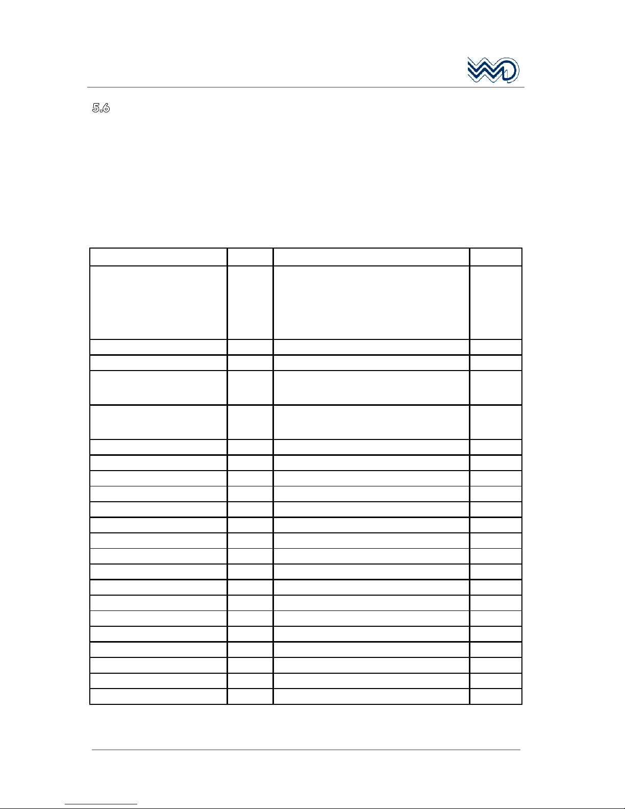
5.6 Environmental Performance Classification
Statement of the Level of Compliance with appropriate JAR TSO.
EUROCAE ED-14D / RTCA DO-160D (29 July 1997), including
Change 1 December 2000.
ENVIRONMENTAL CONDITIONS AND TEST PROCEDURES FOR
AIRBORNE EQUIPMENT PERFORMANCE STANDARD.
NOTE: The following information provides examples only. It is not intended to
be a comprehensive listing of all test conditions.
Conditions Section Description of Conducted Tests Category
Temperature and Altitude
Low Temperature
High Temperature
In-flight Loss of Cooling
Altitude
Decompression
Over Pressure
4.3
4.5.1
4.5.2
4.5.4
4.6.1
4.6.2
4.6.3
Equipment tested to Category
Operation - 20°C / Storage -55°C
Operation +55°C / Storage +85°C
No auxiliary cooling required
50,000 ft / 15,240 m
No test required in Category D1
No test required in Category D1
D1
Temperature Variation 5.2 Equipment tested to Category, 5ºC / min. B
Humidity 6.0 Equipment tested to Standard Category A
Shock 7.1.1
7.2
7.3
Equipment tested to Category
Operational shocks 6g
Crash Safety 20g without damage
B
Vibration (for Helicopter use, the
vibration testing included 4 sets of
Unknown Frequencies of Cat. U).
8.5.1
8.5.2
8.8.1
Equipment tested to Fixed Wing Aircraft Category
Equipment tested to Fixed Wing Aircraft Category
Equipment tested to Helicopter Aircraft Category
S Curve B
S Curve M
R Curve G
Explosion 9.0 No test required X
Waterproofness 10.0 No test required X
Fluids Susceptibility 11.0 No test required X
Sand and Dust 12.0 No test required X
Fungus 13.0 No test required X
Salt Spray 14.0 No test required X
Magnetic Effect 15.0 Equipment tested to Category Z
Power Input 16.0 Equipment tested to Category B
Voltage Spike 17.0 Equipment tested to Category B
Audio Frequency Susceptibility 18.0 Equipment tested to Category B
Induced Signal Susceptibility 19.0 Equipment tested to Category A
Radio Frequency Susceptibility 20.0 Equipment tested to Category T
Radio Frequency Emission 21.0 Equipment tested to Category H
Lightning Induced Susceptibility 22.0 No test required X
Lightning Effects 23.0 No test required X
Icing 24.0 No test required X
Other Test ---- No test required X
Page 43
FSG 2T PS
Portable VHF/AM Airband Transceiver
May 2010 DITTEL D10077
43
Carrying Case PS
Dimensions
Page 44

FSG 2T PS
Portable VHF/AM Airband Transceiver
44
DITTEL D10077 May 2010
Carrying Case PS
Circuit Diagram
Page 45
FSG 2T PS
Portable VHF/AM Airband Transceiver
May 2010 DITTEL D10077
45
6 Option Channel ONLY Mode
IMPORTANT!
The option Channel ONLY Mode may only be activated by
an approved Avionics workshop!
Only for ground based operation a special mode can be set on
request of the customer. Then the operation is limited to the use of
preset channels only; user-selection of frequencies and
programming frequencies in a memory are disabled.
6.1 Activating the option Channel only Mode
The option Channel only Mode is activated by removing a circuit
jumper at the TX/RX board. To set this mode the radio FSG 2T has to
be removed from the 2T PS case and to be opened.
To dismount the transceiver FSG 2T from the Carrying Case PS
remove the two cross-recessed screws 8 and lift off the
matching plate. Carefully pull out the transceiver together with the
wire harness and antenna cable. Disconnect radio from wire
harness and antenna cable.
Connect the radio via a test wiring harness (see Fig. 3-1 of FSG 2T
Installation & Operation Manual) to a test bench setup and supply
the radio with 13.8 VDC. Turn on the radio with the VOL switch on
the front panel.
While in the DIRECT TUNE MODE program up to 20 channels with
the frequencies requested by the customer. See § 4.9.1
Programming while in the DIRECT TUNE MODE of this manual.
Remove the Top Cover of the FSG 2T (see 8.3.1, Maintenance /
Overhaul Manual), and while the radio is still powered, pull off the
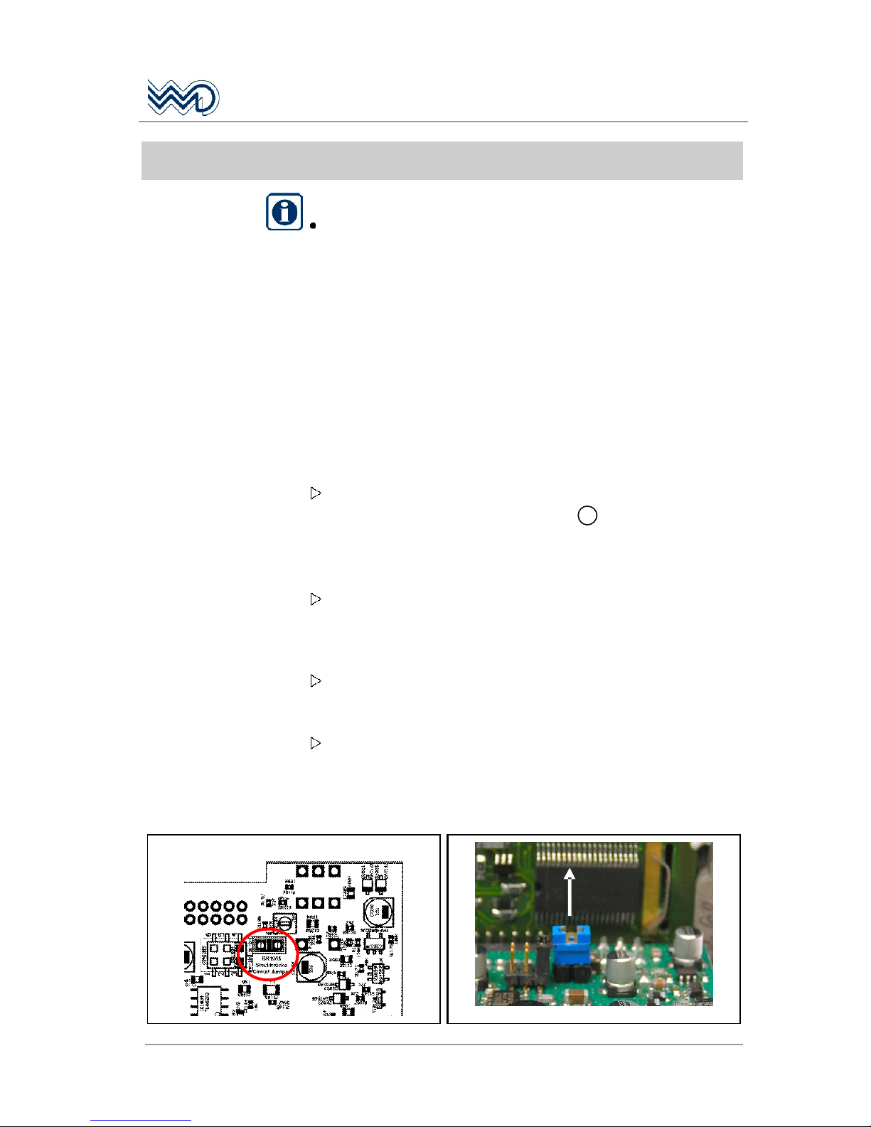
blue circuit jumper BR1005 which is located on the TX/RX board
near the front panel.
Front Panel
BR1005
Steckbrücke
Circuit Jumper
Page 46
FSG 2T PS
Portable VHF/AM Airband Transceiver
46
DITTEL D10077 May 2010
Switch off the radio and disconnect the test wiring harness.
Assemble the radio and fix the Top Cover by appropriate screws.
Ensure the two screening profiles are in position between Top
Cover and Chassis.
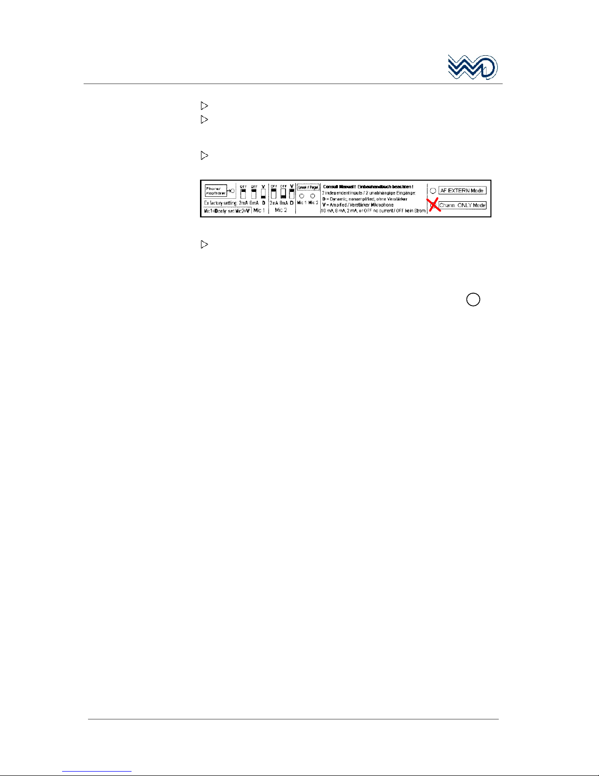
On the Information Label mark permanently the option Chann.
ONLY Mode!
Such a marked radio is allowed only for ground based operation!
To install the transceiver FSG 2T, carefully pull out the wire
harness of the case, connect the 15-pole receptacle and secure it
by the sliding lock. Plug antenna cable and secure it by twisting
the BNC plug. Slowly insert transceiver into the case. Put on the
matching plate and fix it by the two cross-recessed screws 8.
Check fixing and function.
Page 47
FSG 2T PS
Portable VHF/AM Airband Transceiver
May 2010 DITTEL D10077
47
Appendix
Certificates
Page 48
FSG 2T PS
Portable VHF/AM Airband Transceiver
48
DITTEL D10077 May 2010
Page 49
FSG 2T PS
Portable VHF/AM Airband Transceiver
May 2010 DITTEL D10077
49
Page 50
FSG 2T PS
Portable VHF/AM Airband Transceiver
50
DITTEL D10077 May 2010
Page 51

FSG 2T PS
Portable VHF/AM Airband Transceiver
May 2010 DITTEL D10077
51
Page 52
FSG 2T PS
Portable VHF/AM Airband Transceiver
52
DITTEL D10077 May 2010
Page 53

FSG 2T PS
Portable VHF/AM Airband Transceiver
May 2010 DITTEL D10077
53
Page 54

FSG 2T PS
Portable VHF/AM Airband Transceiver
54
DITTEL D10077 May 2010
Page 55

FSG 2T PS
Portable VHF/AM Airband Transceiver
May 2010 DITTEL D10077
55
Copyright Service Information
Copyright 2010
Dittel Messtechnik GmbH
All rights reserved. This document contains proprietary information and such
information may not be disclosed to others for any purpose nor used for
manufacturing purposes without prior written permission of the manufacturer
Dittel Messtechnik GmbH, 86899 Landsberg am Lech, Germany.
In this document no mention is made of patents, trademark rights, or other
proprietary rights which may attach to certain words or entries. The absence
of such mention, however, in no way implies that the words or entries in
question are exempt from such rights.
Service Information
Should any unusual problem arise or further information be desired, please
contact your nearest DITTEL representative or the Dittel Messtechnik
GmbH, Avionics Department, Erpftinger Strasse 36, 86899 Landsberg,
Germany.
The information in this Operator's Manual does not profess to include all the details of
design, production, or variation of the equipment, or to cover all the possible
contingencies which may arise during operation or maintenance. We welcome your
comments concerning this Manual. Although every effort has been made to keep it
free of errors, some may occur. When reporting a specific problem, please describe it
briefly and include the Operator's Manual article number, paragraph or figure
number, and the page number.
Send your comments to Publications Department
Dittel Messtechnik GmbH
Subject to technical changes Printed in Germany
Page 56

FSG 2T PS
Portable VHF/AM Airband Transceiver
56
DITTEL D10077 May 2010
Page 57
 Loading...