

Page 1
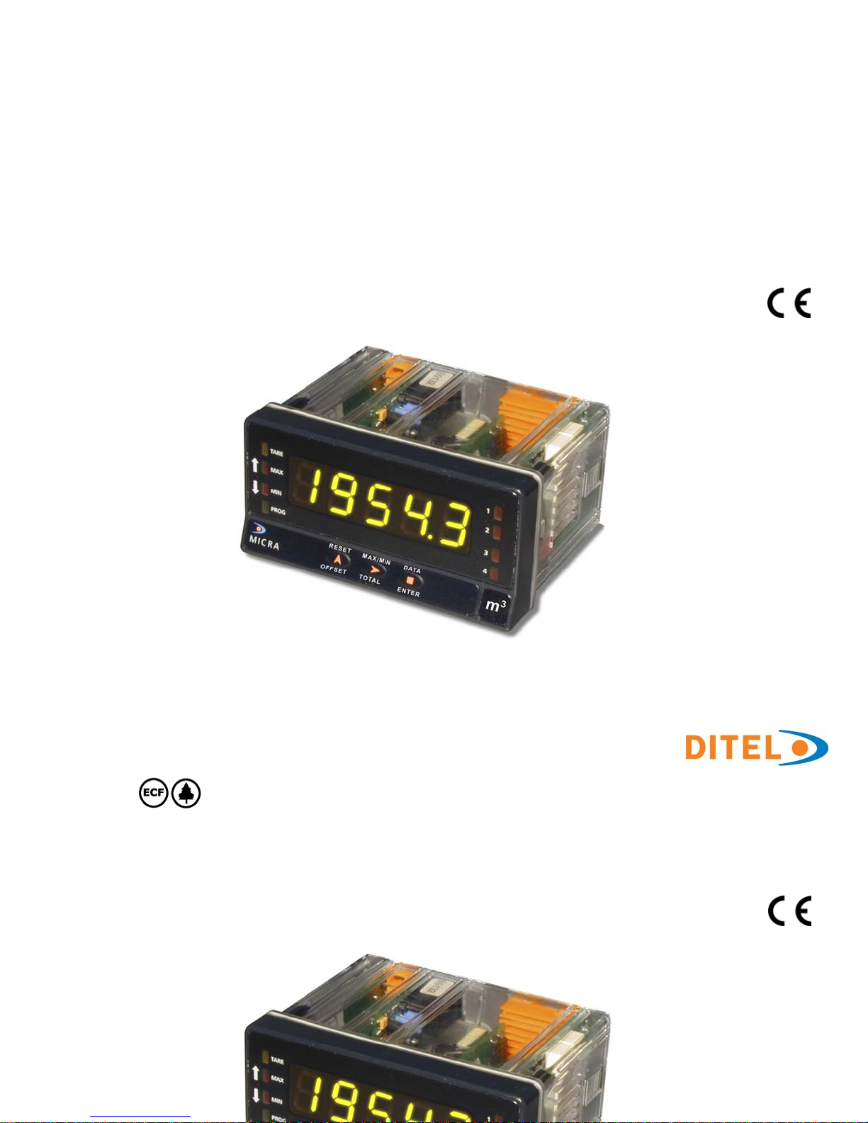
KOSMOS SERIE
MICRA-D
COUNTER - TOTALIZER
TACHOMETER - TOTALIZER
FREQUENCY METER
CHRONOMETER
CODE: 30727293 EDITION: 31-05-2012
INSTRUCTIONS MANUAL
INSTRUCTIONS MANUAL
Page 2

INDEX
1. OVERVIEW ................................................................................................................................................... 4
1.1 Introduction to model Micra D .................................................................................................................. 4
2. GETTING STARTED? .................................................................................................................................... 7
2.1 Dimensions and mounting ....................................................................................................................... 8
2.2 Programming guide ................................................................................................................................. 9
2.3 Power Supply. Connectors ..................................................................................................................... 11
2.4 Description functions keys and LED's in programming mode and mode RUN ............................................. 12
2.5 Input signal (CN2) Connection ............................................................................................................... 13
3. INPUT PROGRAMMING ............................................................................................................................. 14
3.1 Selection of sensor type ........................................................................................................................ 14
3.2 Diagram of programming mode: COUNTER ............................................................................................ 15
3.3 Counter configuration ............................................................................................................................ 16
3.4 Mode count programming ..................................................................................................................... 17
3.5 Programming of display ......................................................................................................................... 19
3.5.1 Options of the Process Variable .................................................................................................... 19
3.5.2 Brightness level configuration ....................................................................................................... 19
3.5.3 Totalizer Option ........................................................................................................................... 20
3.5.4 Totalizer visualization .................................................................................................................. 20
3.6. Programming diagram in MODE: CHRONOMETER .................................................................................. 21
4. CHRONOMETER CONFIGURATION ........................................................................................................... 22
4.1 Run mode programming ........................................................................................................................ 23
5. FREQUENCY METER / TACHOMETER CONFIGURATION ......................................................................... 24
5.1 Frequencymeter / Tachometer ............................................................................................................... 26
5.1.1 Frequencymeter .......................................................................................................................... 26
5.1.2 Tachometer RPM ......................................................................................................................... 26
5.1.3 Tachometer RATE ........................................................................................................................ 27
5.2 Display Setup ....................................................................................................................................... 29
5.2.1 Options of the Process Variable .................................................................................................... 29
5.2.2 TOTAL, MAX and MIN visualization ............................................................................................... 31
2
INDEX
1. OVERVIEW ................................................................................................................................................... 4
1.1 Introduction to model Micra D .................................................................................................................. 4
2. GETTING STARTED? .................................................................................................................................... 7
2.1 Dimensions and mounting ....................................................................................................................... 8
2.2 Programming guide ................................................................................................................................. 9
2.3 Power Supply. Connectors ...................................................................................................................... 11
2.4 Description functions keys and LED's in programming mode and mode RUN .............................................. 12
2.5 Input signal (CN2) Connection ................................................................................................................ 13
3. INPUT PROGRAMMING .............................................................................................................................. 14
3.1 Selection of sensor type ......................................................................................................................... 14
3.2 Diagram of programming mode: COUNTER ............................................................................................. 15
3.3 Counter configuration ............................................................................................................................. 16
Page 3

6. LOGIC FUNCTIONS ............................................................................................................................... 32
6.1 Programmable functions table ................................................................................................................. 33
6.1.1 Logic functions diagram ................................................................................................................ 33
6.2 Program of functions ............................................................................................................................... 34
7. PROGRAM PARAMETERS AND KEYBOARD FUNCTIONS LOCK-OUT ..................................................... 35
7.1 Security menu diagram .......................................................................................................................... 36
8. RESTORATION TO FACTORY CONFIGURATION ................................................................................... 38
9. OUTPUT OPTIONS ................................................................................................................................ 39
9.1 SETPOINTS OUTPUT ............................................................................................................................. 41
9.1.1 Introduction ................................................................................................................................. 40
9.1.2 Installation .................................................................................................................................. 42
9.1.3 Wiring ......................................................................................................................................... 42
9.1.4 Technical specifications ................................................................................................................ 43
9.1.5 Setpoints menu diagram in mode Frequencymeter / Tachometer .................................................... 44
9.1.6 Direct access to the setpoints value programming .......................................................................... 44
9.1.7 Description of operation in mode Frequencymeter, Tachometer ...................................................... 45
9.1.8 Setpoints menu Diagram in mode Counter / Chronometer .............................................................. 46
9.1.9 Description of mode relays operating as Counter / Chronometer ..................................................... 46
9.2 OUTPUT RS2/ RS4 ................................................................................................................................. 48
9.2.1 Introduction ................................................................................................................................. 48
9.2.1 Diagram of the menu Input RS ..................................................................................................... 49
9.3 ANALOG OUTPUT .................................................................................................................................. 53
9.3.1 Introduction ................................................................................................................................. 53
9.3.2 Installation of NMA or NMV option ................................................................................................. 53
9.3.3 Connection .................................................................................................................................. 54
9.3.4 Technical specifications ................................................................................................................ 55
9.3.5 Analog output menu diagram ........................................................................................................ 55
10. TECHNICAL CHARACTERISTICS ......................................................................................................... 56
DECLARATION OF CONFORMITY ........................................................................................................................ 58
WARRANTY .............................................................................................................................................. 59
3
6. LOGIC FUNCTIONS ............................................................................................................................... 32
6.1 Programmable functions table .................................................................................................................. 33
6.1.1 Logic functions diagram ................................................................................................................. 33
6.2 Program of functions ............................................................................................................................... 34
7. PROGRAM PARAMETERS AND KEYBOARD FUNCTIONS LOCK-OUT ...................................................... 35
7.1 Security menu diagram .......................................................................................................................... 36
8. RESTORATION TO FACTORY CONFIGURATION .................................................................................... 38
9. OUTPUT OPTIONS ................................................................................................................................. 39
9.1 SETPOINTS OUTPUT .............................................................................................................................. 41
9.1.1 Introduction ................................................................................................................................. 40
9.1.2 Installation ................................................................................................................................... 42
9.1.3 Wiring .......................................................................................................................................... 42
Page 4

4
1. OVERVIEW
1.1 Introduction to model Micra D
The MICRA-D model from the KOSMOS SERIE is a five-digit digital instrument with 2 programmable inputs that accept
signals from a variety of standard sensors and pulse generators. Can be configured to work as:
- TACHOMETER + TOTALIZER (8 digits)
- TACHOMETER + DIRECTION OF ROTATION INDICATION
- FREQUENCYMETER
- COUNTER 5 digits + TOTALIZADOR (8 digits)
- SEVERAL MODES OF COUNTER (UP, DOWN, UP/ DOWN, PHASE)
- CHRONOMETER (5 digits)
The basic instrument is a soldered assembly composed of a main board, a tricolor programmable display and a
power circuit.
Standard features of the basic instrument include the reading of the input variable as well as remote hold, reading
and memorisation of max and min values (peak/ valley), tare and reset function, and a full complement of
programmable logic functions.
MICRA-D model can also incorporate the following output options:
COMMUNICATION
RS2 Serial RS232C
RS4 Serial RS485
CONTROL
NMA Analogue 4-20mA
NMV Analogue 0-10V
2RE 2 Relays SPDT 8A
4RE 4 Relays SPST 5A
4OP 4 NPN output
4OPP 4 PNP output
All the output options are opto-isolated from input signal and power supply.
1. OVERVIEW
1.1 Introduction to model Micra D
The MICRA-D model from the KOSMOS SERIE is a five-digit digital instrument with 2 programmable inputs that accept
signals from a variety of standard sensors and pulse generators. Can be configured to work as:
- TACHOMETER + TOTALIZER (8 digits)
- TACHOMETER + DIRECTION OF ROTATION INDICATION
- FREQUENCYMETER
- COUNTER 5 digits + TOTALIZADOR (8 digits)
- SEVERAL MODES OF COUNTER (UP, DOWN, UP/ DOWN, PHASE)
- CHRONOMETER (5 digits)
The basic instrument is a soldered assembly composed of a main board, a tricolor programmable display and a
power circuit.
Page 5

5
PROCESS COUNTER
UP counter, DOWN counter and bidirectional
UP/DOWN counter
• In UP/ DOWN mode it can be programmed to
work: Independent, Directional or Phase.
• Remote and front-panel reset
• Decimal point indication
• Reset may load a count value (OFFSET),
programmable or entered from the display
• Multiplier/Divider factor from 0.0001 to 99999
• Programmable low frequency debounce filter (20
Hz) activates automatically when a contact closure
input type is selected.
• Key-lock for RESET
TOTALIZER COUNTER
• Selectable totalizer with separate decimal point and
scale factor independent from process counter.
• Count display from 99999999 to -9999999. Decimal
point position programmable.
• Selectable 4 positions decimal point
• Input configuration and count mode is the same as
selected for the process counter
•
Alternating display of 4 digits high order part and 4
digits low order part of the value with corresponding
indication H and L.
• No offset possibility
• Key-lock for the RESET function
• Remote and front-panel reset
• Scale factor from 0.0001 to 99999
CHRONOMETER
• Four ranges 999,99s, 999m59s, 999h59m, 9999.9h
• Remote and front-panel reset
• Reset may load a count value (OFFSET), programmable
or entered from the display
• Counts UP or DOWN
• Key-lock for RESET
FREQUENCY METER / TACHOMETER
• Measures frequency, rpm, rate, flow and time
.
• Decimal point indication
• Scale factor programmable from 0.0001 to 9999
• Display update time programmable from 0.1 to 9.9s
• Pulse arrival time limit programmable from 1 to 99.9s
• MAX and MIN values memorisation (TACHOMETER)
PROCESS COUNTER
UP counter, DOWN counter and bidirectional
UP/DOWN counter
• In UP/ DOWN mode it can be programmed to
work: Independent, Directional or Phase.
• Remote and front-panel reset
• Decimal point indication
• Reset may load a count value (OFFSET),
programmable or entered from the display
• Multiplier/Divider factor from 0.0001 to 99999
• Programmable low frequency debounce filter (20
Hz) activates automatically when a contact closure
input type is selected.
• Key-lock for RESET
•
Alternating display of 4 digits high order part and 4
digits low order part of the value with corresponding
indication H and L.
• No offset possibility
• Key-lock for the RESET function
• Remote and front-panel reset
• Scale factor from 0.0001 to 99999
CHRONOMETER
• Four ranges 999,99s, 999m59s, 999h59m, 9999.9h
• Remote and front-panel reset
• Reset may load a count value (OFFSET), programmable
or entered from the display
• Counts UP or DOWN
Page 6

TACHOMETER WITH DIRECTION INDICATION
• The MICRA-D senses direction of rotation and
indicates polarity of the signal by means of LED’s
represented by up and down arrows. This function
requires programming the totalizer for up/down
PHASE or DIREC mode.
TACHOMETER WITH TOTALIZER COUNTER
• The totalizer has the same scaling facilities as for the
counter configuration thus allowing to have two
simultaneous information of the same signal, for
example speed and flow.
13 programmable logic functions operated at the
rear connector enhance the functionality of the
meter and allow controlling basic operations
remotely.
In addition 18 commands through the serial port are
available to allow reading and changing the setpoint
values, request the display and reset to zero, etc...
Special software capabilities are program lock-out
for individual menus or the entire program
parameters, as well as the return to the factory
configuration.
Programmable display color (red, green or amber)
assignable to: programming, partial count value,
total, setpoints, relay activation etc.
6
This instrument conforms the following community standards: 89/336/CEE y 73/23/CEE
Warning: Refer to the instructions manual to preserve safety protections.
TACHOMETER WITH DIRECTION INDICATION
• The MICRA-D senses direction of rotation and
indicates polarity of the signal by means of LED’s
represented by up and down arrows. This function
requires programming the totalizer for up/down
PHASE or DIREC mode.
TACHOMETER WITH TOTALIZER COUNTER
• The totalizer has the same scaling facilities as for the
counter configuration thus allowing to have two
simultaneous information of the same signal, for
example speed and flow.
13 programmable logic functions operated at the
rear connector enhance the functionality of the
meter and allow controlling basic operations
remotely.
In addition 18 commands through the serial port are
available to allow reading and changing the setpoint
values, request the display and reset to zero, etc...
Special software capabilities are program lock-out
for individual menus or the entire program
parameters, as well as the return to the factory
Page 7

7
2. GETTING STARTED
Packing contents
Instruction manual in English including declaration of conformity
Digital panel meter MICRA-D.
Accessories for panel mounting (sealing gasket and fixing clips).
Accessories for wiring connections (plug-in terminal block connectors with a fingertip key).
Wiring label stuck to the MICRA-D case.
4 set of labels with engineering units.
9
Check the packing contents.
Programming instructions
The Instrument includes software that allows, via keyboard, accessing to several independent programming menus
for configuration of the input, the display and the logic functions. If additional options are installed (serial outputs,
analogue output and relays output, once recognised by the instrument, they activate their own programming
software.
9
Read carefully this section.
Programming lock-out (Page 35).
Software allows total programming lockout but also selective lockout of the programming parameters.
The instrument is delivered from factory with unlocked programming, e.g., with all the programming levels
accessible to the operator
Write down the security code and keep it in a secure place.
2. GETTING STARTED
Packing contents
Instruction manual in English including declaration of conformity
Digital panel meter MICRA-D.
Accessories for panel mounting (sealing gasket and fixing clips).
Accessories for wiring connections (plug-in terminal block connectors with a fingertip key).
Wiring label stuck to the MICRA-D case.
4 set of labels with engineering units.
9
Check the packing contents.
Programming instructions
Page 8
ANALOGUE
OUTPUT
OPTION
(NMA/ NMV)
RS232C/ RS485
8
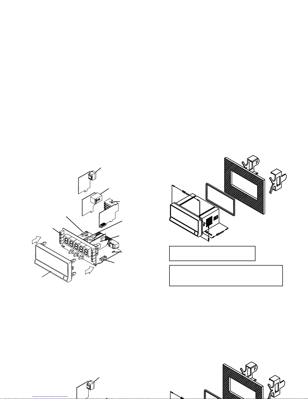
The figure below shows the locations of the different output options available.
The 2RE, 4RE, 4OP y 4OPP options are alternative and only one of them can be installed in the M1 connector.
The RS2 y RS4 options are also alternative and only one of them can be installed in the M2 connector.
The NMA or NMV are also alternative and only one of them can be installed in the M3 connector.
Up to three output options can be installed and operate simultaneously:
- 4-20mA or 0-10V (only one)
- RS232C or RS485 (only one)
- 2 RELAYS, 4 RELAYS or 4 OPTO (only one).
FRONT PANEL
COVER
ANALOGUE
OUTPUT
OPTION
(NMA/ NMV)
MAIN BOARD
RS232C/ RS485
OUTPUT
DISPLAY
RELAYS/ OPTO
OUTPUT
POWER FILTER
CIRCUIT
M3
CONNECTOR FOR
ANALOGUE OUTPUT
M1
CONNECTOR
RELAYS OUTPUT
M2
CONNECTOR FOR RS
OUTPUT
2.1 Dimensions and mounting
Front: 96 x 48 mm Depth: 60 mm
Panel cut-out: 92 x 45 mm
CLEANING: frontal cover should be cleaned only with a
soft cloth soaked in neutral soap product.
DO NOT USE SOLVENTS
The figure below shows the locations of the different output options available.
The 2RE, 4RE, 4OP y 4OPP options are alternative and only one of them can be installed in the M1 connector.
The RS2 y RS4 options are also alternative and only one of them can be installed in the M2 connector.
The NMA or NMV are also alternative and only one of them can be installed in the M3 connector.
Up to three output options can be installed and operate simultaneously:
- 4-20mA or 0-10V (only one)
- RS232C or RS485 (only one)
- 2 RELAYS, 4 RELAYS or 4 OPTO (only one).
2.1 Dimensions and mounting
Page 9
59
2.2 Programming guide
How to get into programming mode?
First, plug the instrument to the corresponding supply, automatically a display test will be done and after that the software
version will be shown then the instrument will go to work mode. Second, press the
key to enter into the programming
mode, the indication "-Pro-" will appear on the display then.
How to store programmed parameters?
If we want to save the changes that we have done in the programming, we must complete the programming of all the
parameters contained in the routine we are in. In the last step of the routine, as a result of pressing on the
key,
“StorE” will de displayed during a few seconds, meanwhile all the data are stored in memory. Then the instrument will go
back to working mode.
How is programming routine organised?
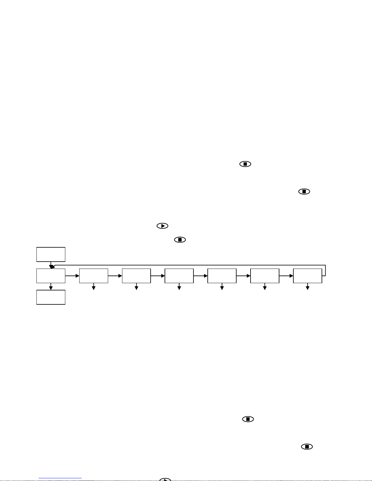
Programming software is composed by a number of menus and submenus hierarchically organized. On figure below,
beginning with indication "-Pro-", press repeatedly
to get access to programming menus. Modules 3, 4 and 5 will only
be shown if the option for setpoints, analogue output or RS option has been plugged in. Selecting one menu, the access to
the different programming submenus is done by pressing
.
-Pro-
CnInP
Input
Selection
StorE
RUN
CndSP SEtP Anout rSout LoGIn
Display
Configuration
Setpoints
Configuration
Analogue
Output
Configuration
RS Output
Configuration
Logic
Functions
Module selection level
2.2 Programming guide
How to get into programming mode?
First, plug the instrument to the corresponding supply, automatically a display test will be done and after that the software
version will be shown then the instrument will go to work mode. Second, press the
key to enter into the programming
mode, the indication "-Pro-" will appear on the display then.
How to store programmed parameters?
If we want to save the changes that we have done in the programming, we must complete the programming of all the
parameters contained in the routine we are in. In the last step of the routine, as a result of pressing on the
key,
“StorE” will de displayed during a few seconds, meanwhile all the data are stored in memory. Then the instrument will go
back to working mode.
How is programming routine organised?
Programming software is composed by a number of menus and submenus hierarchically organized. On figure below,
Page 10

10
Accessing to programmed parameters
Thanks to the tree structure, the programming routines allow to access to one parameter and modify it without passing
through the whole list of parameters.
To advance through programming
The progress through the programming routines is done by pressing
key.
In general, the steps to be done will be push
key a certain number of times to select an option and push key to
validate the change and going forward to the next step of the program.
The numerical values are programmed digit by digit as explained in the next paragraph.
Programming numerical values
When the parameter is a numerical value, the first of the digits to be programmed will appear blinking on display.
The method of introducing a value is as follow:
Digit selecting: Press repeatedly the key to shift from left to right over all the display digits included the LED
direction indicators (when the programmed function requires it).
Changing the digit value: Press repeatedly the
key to increase the value of blinking digit until it has the desired
value or to alternate the LED Up and Down arrows indicators (MAX and MIN).
Selecting an option from the list
When the parameter is an option to be chosen among different possibilities, the
key allows you to browse through
the list of options until you find the desired parameter
Accessing to programmed parameters
Thanks to the tree structure, the programming routines allow to access to one parameter and modify it without passing
through the whole list of parameters.
To advance through programming
The progress through the programming routines is done by pressing
key.
In general, the steps to be done will be push
key a certain number of times to select an option and push key to
validate the change and going forward to the next step of the program.
The numerical values are programmed digit by digit as explained in the next paragraph.
Programming numerical values
When the parameter is a numerical value, the first of the digits to be programmed will appear blinking on display.
The method of introducing a value is as follow:
Page 11
2.1 - Alimentación y conectores
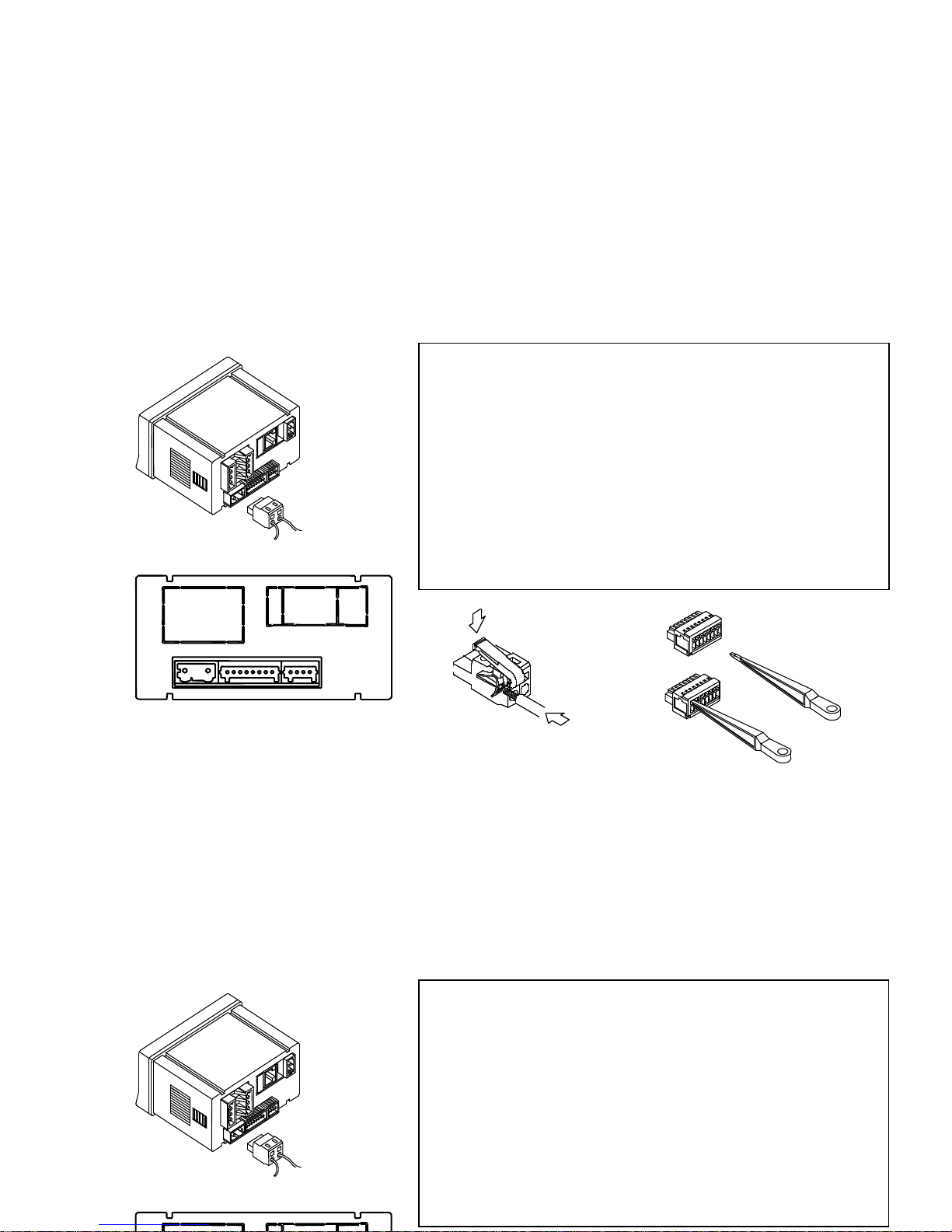
2.3 – Power supply and connectors
CN1
1 2
1
2
WIRING and POWER SUPPLY RANGE
MICRA-D
85 V – 265 V AC 50/ 60 Hz or 100 – 300 V DC
MICRA-D6
22 – 53 V AC 50/ 60 Hz or 10,5 - 70 V DC
Borne 1: Phase
Borne 2: Neutral
NOTE: When DC power supply (direct) polarity
in connector CN1 is indistinct.
WARNING: If not installed and used in accordance with these
instructions, protection against hazards may be impaired.
In order to guarantee the electromagnetic compatibility, the following
guidelines should be kept in mind:
- Power supply wires may be routed separated from signal wires.
- Never run power and signal wires in the same conduit.
- Use shielded cable for signal wiring and connect the shield to the ground.
- The cables section should be
>0.25 mm
2
INSTALLATION
To meet the requirements of the directive EN61010-1, where the unit is
permanently connected to the mains supply, it is obligatory to install a circuit
breaking device easy reachable to the operator and clearly marked as the
disconnect device.
CONNECTORS
CN1 To perform wiring connections, strip the wire leaving from 7 and 10 mm
exposed to air and insert it in the proper terminal while pushing the fingertip
down to open the clip inside the connector as indicated in the figures.
Each terminal accepts cables of section between 0.08 mm² and 2.5 mm² (AWG
26 ÷ 14).
11
2.3 – Power supply and connectors
1
2
WARNING: If not installed and used in accordance with these
instructions, protection against hazards may be impaired.
In order to guarantee the electromagnetic compatibility, the following
guidelines should be kept in mind:
- Power supply wires may be routed separated from signal wires.
- Never run power and signal wires in the same conduit.
- Use shielded cable for signal wiring and connect the shield to the ground.
- The cables section should be
>0.25 mm
2
INSTALLATION
To meet the requirements of the directive EN61010-1, where the unit is
permanently connected to the mains supply, it is obligatory to install a circuit
breaking device easy reachable to the operator and clearly marked as the
disconnect device.
Page 12
12
ENTER
RESET
OFFSET
MAX/MIN
TOTAL
PROG
MIN
MAX
TARE
1
2
3
4
DATA
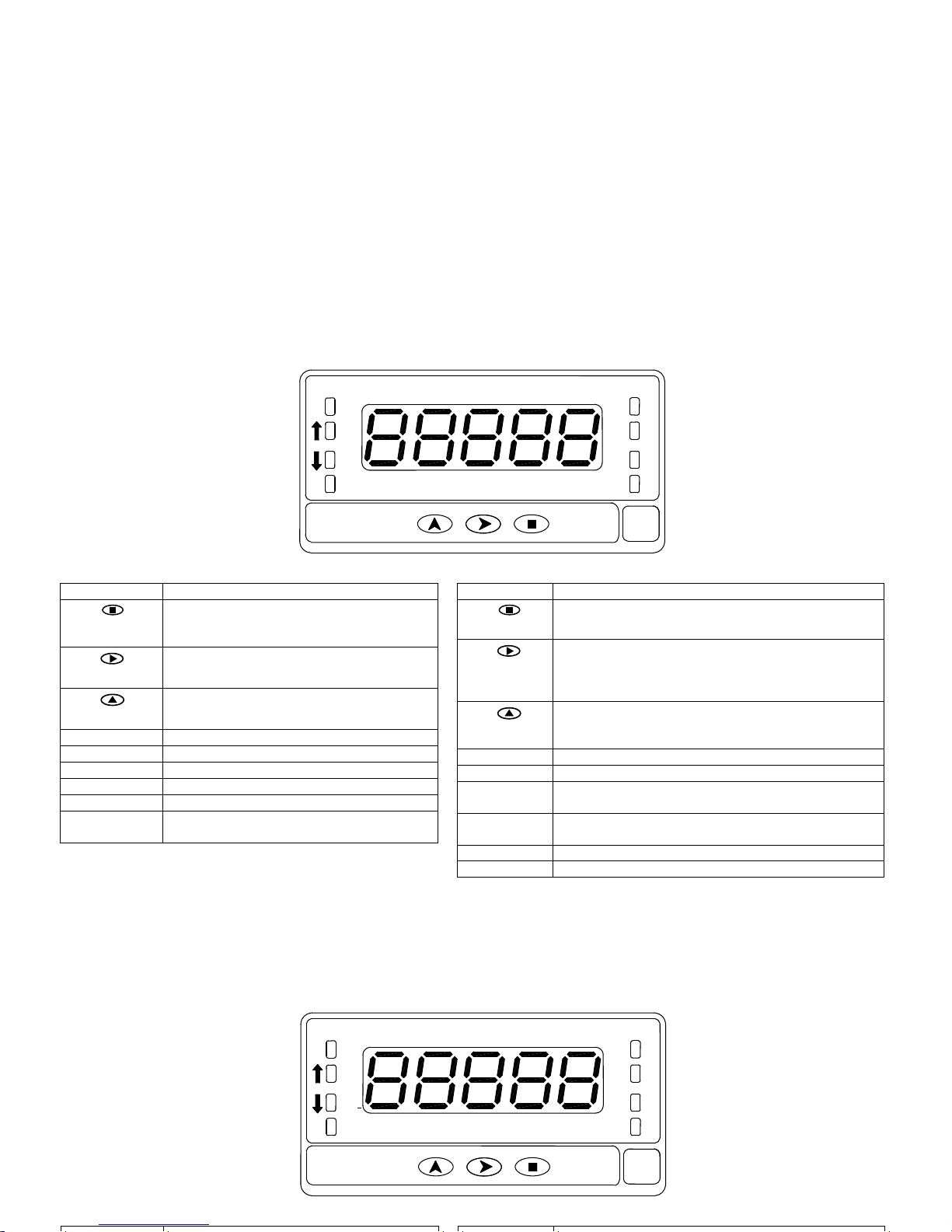
2.4 Functions keys and LED's description in programming mode and RUN mode
KEY Function in programming mode
DATA
ENTER
- to step forward in programming menu
- to validate programmed values
- to exit programming menu
MAX/ MIN
TOTAL
- to move blinking digit
RESET
OFFSET
- to increase blinking digit value
- Direct access to Setpoints value
LED’s Function in programming mode
TARE
MAX
Indicates rotation sense (polarity)
MIN
Indicates rotation sense (polarity)
PROG
Indicates you are in programming mode
1- 2 - 3 - 4
Indicates the Setpoint that is being
programmed
KEY Function in RUN mode
DATA
ENTER
- to enter programming menu or to visualize
parameters if programming is locked
MAX/ MIN
TOTAL
1st stroke allows TOTALIZER visualization (if activated)
2nd stroke allows Max visualization ( only Tachometer)
3ª stroke allows Min visualization ( only Tachometer)
Following stroke: back to current value.
RESET
OFFSET
In Tachometer mode reset of MAX/ MIN/ TOTAL (if
present on display)
In Counter mode Reset / OFFSET (starts measuring)
LED’s Function in RUN mode
TARE
Indicates that there is an offset value programmed
MAX
Fixed indicates rotation sense or count polarity
Blinking indicates visualization of a Max value
MIN
Fixed indicates rotation sense or count polarity
Blinking indicates visualization of a Min value
PROG
Not active in run mode
1- 2 - 3 - 4
Indicates the activated Setpoint
ENTER
RESET
OFFSET
MAX/MIN
TOTAL
PROG
MIN
MAX
TARE
1
2
3
4
DATA
2.4 Functions keys and LED's description in programming mode and RUN mode
Page 13
13
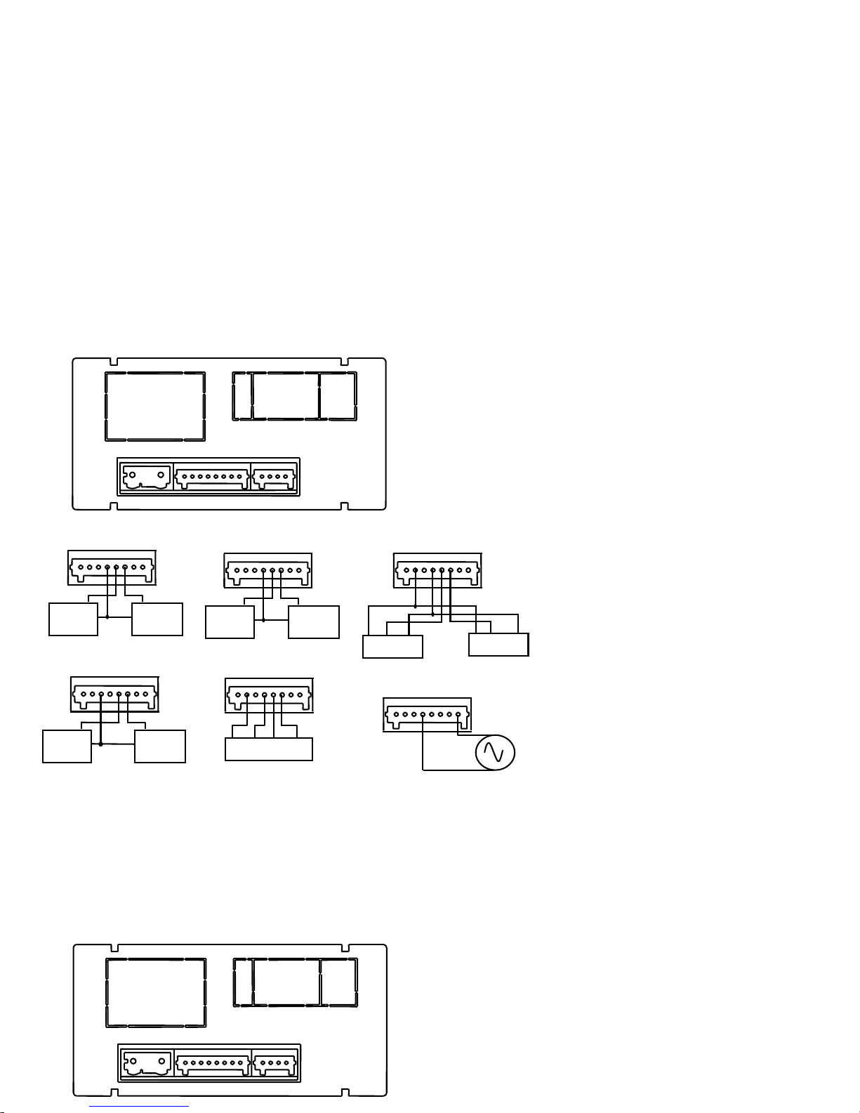
2.5 – Input signal (CN2) Connection
Refer to connection recommendations on page 11
CN2
PIN 1 = No Connection
PIN 2 = (+) 18 V Excitation
PIN 3 = (+) 8,2 V Excitation Namur sensors
PIN 4 = ( - ) Common excitation / input
PIN 5 = Signal B input
PIN 6 = Signal A input
PIN 7 = No Connection
PIN 8 = High voltage input (300 Vac max.)
CN2
1 2 3 4 5 6 7 8
Instrument´s rear view
2.5 – Input signal (CN2) Connection
Refer to connection recommendations on page 11
CN2
PIN 1 = No Connection
PIN 2 = (+) 18 V Excitation
PIN 3 = (+) 8,2 V Excitation Namur sensors
PIN 4 = ( - ) Common excitation / input
PIN 5 = Signal B input
PIN 6 = Signal A input
PIN 7 = No Connection
PIN 8 = High voltage input (300 Vac max.)
CN2
1 2 3 4 5 6 7 8
Instrument´s rear view
CN2
1 8
MAGNETIC PICKUP
Secondary
Principal
CN2
1 8
CONTACT CLOSURE
Secondary
Principal
1
CN2
8
NAMUR sensor
Secondary
Principal
CN2
1 8
ENCODER
EXC COMM OUTB OUTA
ENCODER
CN2
1 8
PNP/ NPN SENSOR
Exc Out Comm
Secondary
Exc Out Comm
Principal
CN2
1 8
10- 300 Vac
Page 14
14
3. INPUT PROGRAMMING
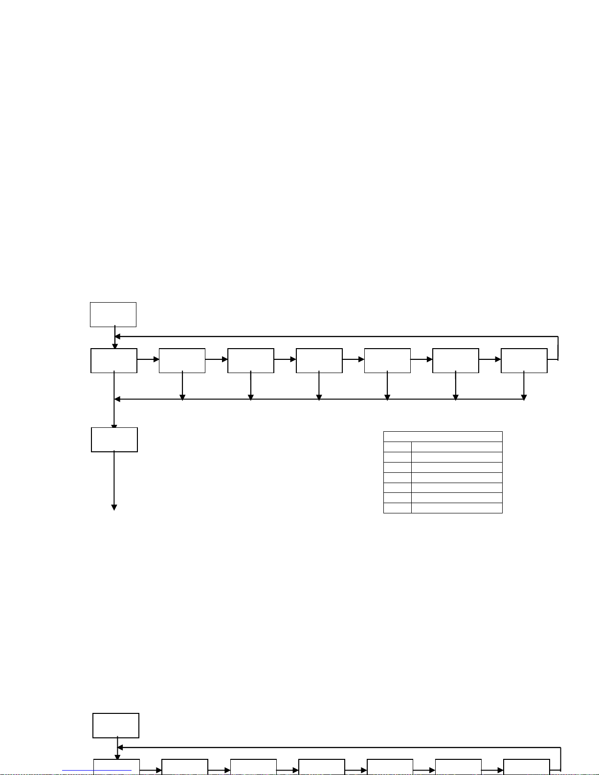
3.1 Selection of sensor type
The diagram below shows first the configuration menu of the different sensors types, next step is then going to the run
mode selection.
When selecting Contact closure sensor type, anti rebound filter will activate automatically
Both input channels are programmed automatically for the same type of sensor input.
CnInP
- 1 - -2 -
- 3 - -4 - -5 -
- 6 - -7 -
MODE
INPUT TYPE
1 10 to 300 V ac
2 Magnetic pickup
3 NAMUR sensor
4 PNP sensor
5 NPN sensor
6 TTL/ 24 V Encoder
7 Contact closure
3. INPUT PROGRAMMING
3.1 Selection of sensor type
The diagram below shows first the configuration menu of the different sensors types, next step is then going to the run
mode selection.
When selecting Contact closure sensor type, anti rebound filter will activate automatically
Both input channels are programmed automatically for the same type of sensor input.
CnInP
- 1 - -2 -
-3 - -4 - -5 -
- 6 - -7 -
Page 15
15
MODE
COUNT
CHRON FREC TAC
UP DOWN
In-A In A-B
PrO
PHASE
UP-DOWN
INDEP DIR
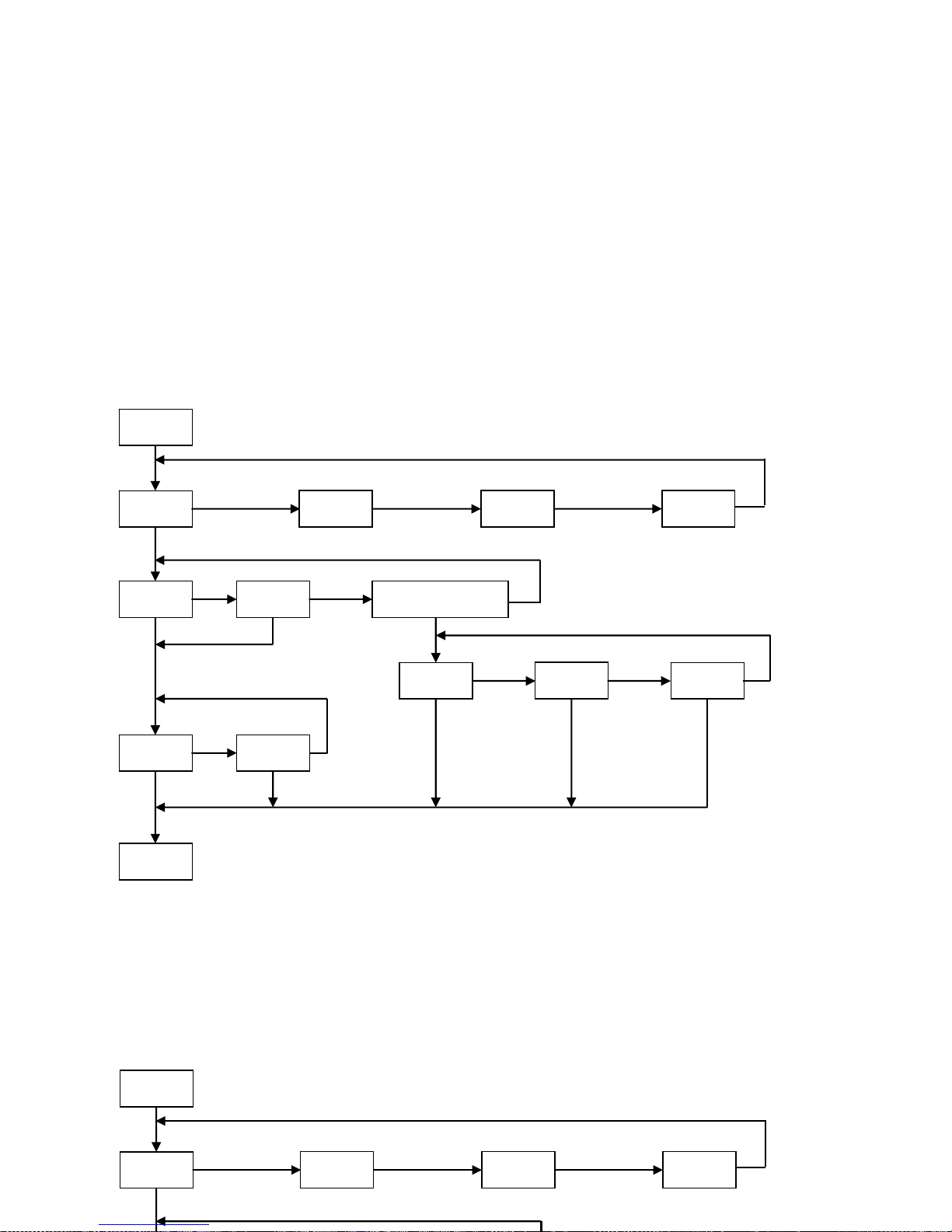
3.2 COUNTER mode programming diagram
MODE
COUNT
CHRON FREC TAC
3.2 COUNTER mode programming diagram
Page 16

16
3.3 Counter configuration
INPUTS
The counter has two inputs, the A input receives the
pulses to count, and the B input serves to inhibit the
count or to change the count direction, except in case of
bidirectional counter IndEP where the second input is
also used to count pulses.
PULSE MEASUREMENT
The pulses applied to the input are detected in the rising
edge and immediately update the value of the counter
and the setpoints status if the card is installed. The
display updates every 100 ms. In a power failure or
disconnection from the supply source, the instrument
keeps the count values.
VARIABLES
The main variable of the counter is the PROCESS
variable that is the number of pulses registered from the
last RESET operation.
If the totalizer option is enabled, we have PROC and
TOTAL variables.
The TOTAL variable counts the total number of pulses
received, independently of the reset operations that may
take place in the process display.
DISPLAY
Process: The limits of the display are 99999 and -
99999. When the instrument exceeds 99999, it shows
OVER, and when it falls below -99999, it shows UNDER.
The positive sign is indicated by the red LED Up arrow
located on the left side of the display and the negative
sign is indicated by the red LED Down arrow located on
the left side of the display.
The decimal point can be located in anyone of the digits
of the display, and it has not value, that is, the display
always shows the whole part of the measurement.
Total: The limits of the display are 99999999 and
-9999999. When the instrument exceeds these limits the
display shows the indications OVER or UNDER.
The negative sign, when the value has less than five
digits, appears in the most significant digit of the
display.
The negative sign is indicated by the MIN LED.
When the total value has more than five digits, the
display alternates the 4 digits high order part and the 4
digits low order part (the letters 'H' and 'L' in the
auxiliary digit indicate which part is on display.
The decimal point can be located in anyone of the digits
of the low part, and it does not have value, the display
shows the whole part of the measurement.
3.3 Counter configuration
INPUTS
The counter has two inputs, the A input receives the
pulses to count, and the B input serves to inhibit the
count or to change the count direction, except in case of
bidirectional counter IndEP where the second input is
also used to count pulses.
PULSE MEASUREMENT
The pulses applied to the input are detected in the rising
DISPLAY
Process: The limits of the display are 99999 and -
99999. When the instrument exceeds 99999, it shows
OVER, and when it falls below -99999, it shows UNDER.
The positive sign is indicated by the red LED Up arrow
located on the left side of the display and the negative
sign is indicated by the red LED Down arrow located on
the left side of the display.
The decimal point can be located in anyone of the digits
of the display, and it has not value, that is, the display
Page 17
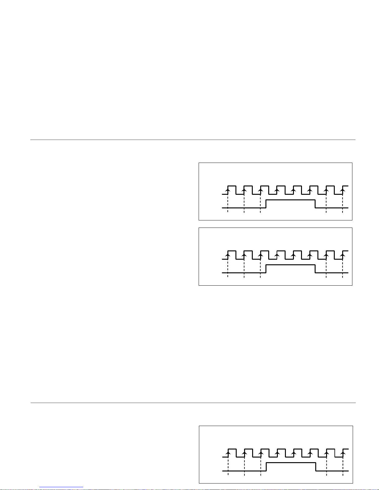
3.4. Mode count programming
The input setup is available on the 'CnInp' module which
allows configuration of the count mode and batch operation.
3.1.1. Count Modes
The software provides setup for five different count modes:
uP
Up count
do
Down count.
In-A
Allows count on A input regardless of input B
InA-B
Pulses applied at the A input are added or subtracted to the
count display if the B input is at low level and being used as
inhibited input.
uP-do IndEP
Pulses applied at the A input are added to the count display
while pulses at the B input are subtracted.
uP-do dIrEC
When B input is at low level, the pulses applied at the A
input increment the count. When B input is at high level, the
pulses at the A input decrement the count.
uP-do PHASE
The rising edges at the A input increment the count if the B
iinput is at low level. The falling edges at the A input
decrement the count if the B input is at low level.
Unidirectional counters:
MODE UP INA-B
A counts up if B is '0'. B inhibits count.
1
p
rocess
in
p
ut
A
input B
23 45
MODE DO INA-B
A counts down if B is '0'. B inhibits count.
8
p
rocess
in
p
ut
A
input B
76 54
17
3.4. Mode count programming
The input setup is available on the 'CnInp' module which
allows configuration of the count mode and batch operation.
3.1.1. Count Modes
The software provides setup for five different count modes:
uP
Up count
do
Down count.
In-A
Allows count on A input regardless of input B
Unidirectional counters:
MODE UP INA-B
A counts up if B is '0'. B inhibits count.
1
p
rocess
in
p
ut
A
input B
23 45
Page 18
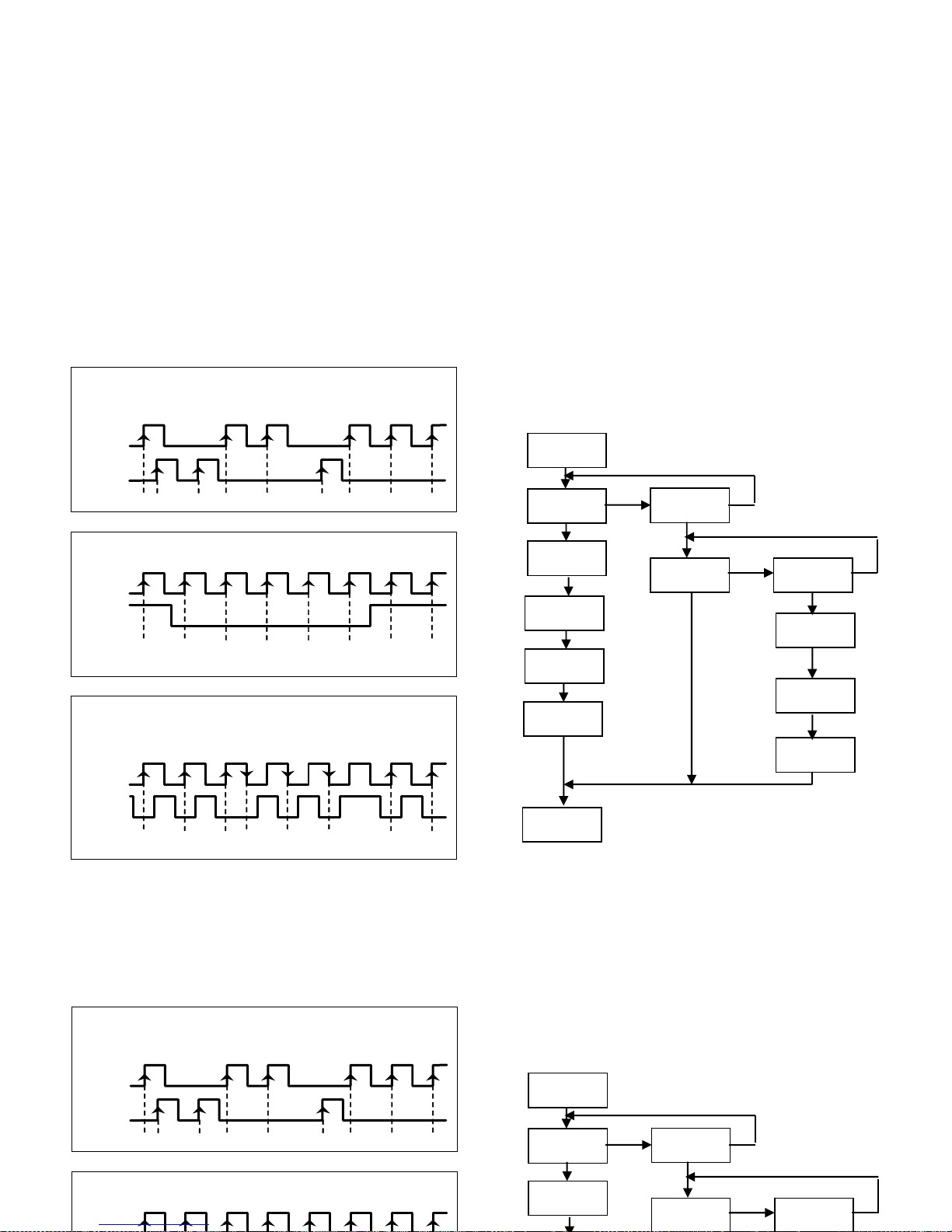
Bidirectional counters:
MODE UP-DO INDEP
A counts up. B counts down.
1
p
rocess
in
p
ut A
input B
0 -1 2 3
0 1 0 1
MODE UP-DO DIREC
A counts up if B is ‘0’ and counts down if B is ‘1’
1
p
rocess
in
p
ut A
input B
2 3 4 3
-1 20
MODE UP-DO PHASE
Rising edge of A counts up if B is ‘0’. Falling edge of A
counts down if B is ‘0’.
1
p
rocess
in
p
ut A
input B
2 3 1 2
10 2
CndSP
PrOC
tOtAL
PrO
dCdiS
OFFSEt
dcFAC
FACdi
nO
dCtOt
dCFAC
YES
FACtO
Programming diagram of the
DISPLAY in MODE: COUNTER
18
Bidirectional counters:
MODE UP-DO INDEP
A counts up. B counts down.
1
p
rocess
in
p
ut A
input B
0 -1 2 3
0 1 0 1
MODE UP-DO DIREC
A counts up if B is ‘0’ and counts down if B is ‘1’
CndSP
PrOC
tOtAL
dCdiS
nO
YES
Programming diagram of the
DISPLAY in MODE: COUNTER
Page 19
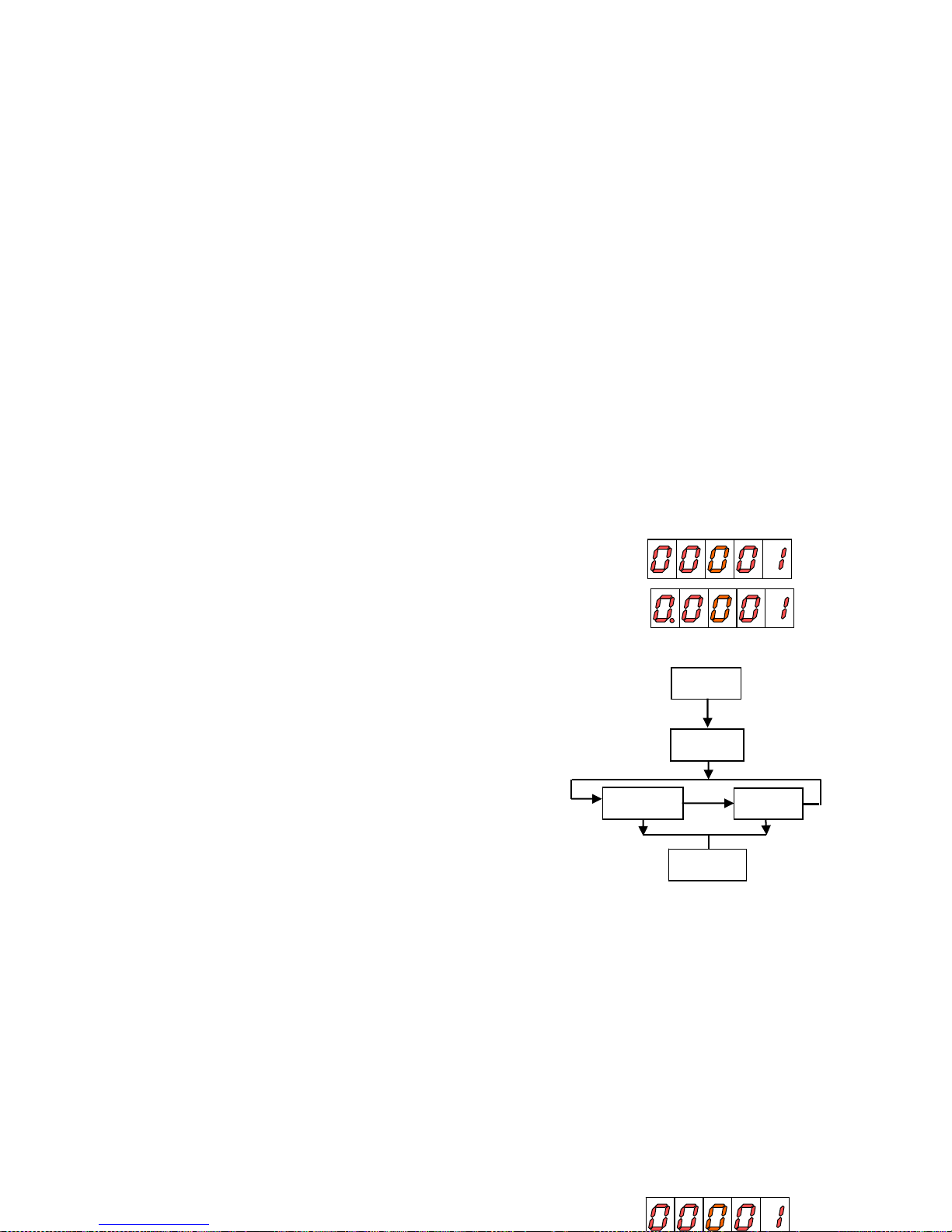
3.5. Scaling setup
3.5.1. Options of the Process Variable
In the menu ProC of the CndSP module can be found the
parameters related to the PROCESS variable measurement, Decimal Point, Offset, Multiplier Factor-
DECIMAL POINT
The decimal point indication helps to read the display in the
desired engineering units.
The decimal point has no real value, i.e. the digits to the right
of the decimal point are not actually decimals. To read values
with resolution to the desired decimal places is achieved by a
combination of decimal point and scaling factor.
For example, suppose a system that provides 100 pulses per 2
meters length of a material. To display length in meters and
centimeters, you should program a factor of 2 (1 pulse = 2
cms) and place the decimal point to the third digit.
OFFSET
OFFSET is the value that takes the counter in a reset event.
By default it is zero whatever is the configuration.
Configurable in the menu ProC
The OFFSET is applied to the PROCESS variable exclusively.
When the OFFSET is different from zero, the LED TARE will
remain active while in the run mode.
SCALE FACTOR
The scale factor is programmable from 0.00001 to 99999.
Individual decimal point location makes possible to
program any value within this range independently from
the main decimal point of the display.
Any number below 1 act like a divisor while a number
above 1 acts like a multiplier. (It is not possible to program
a factor=0).
19
3.5.2 Configuration of display brightness level
CndSP
Enter > 3 s.
BriGH
-HI-
-Lo-
Pro
3.5. Scaling Setup
3.5.1. Options of the Process Variable
In the menu ProC of the CndSP module can be found the
parameters related to the PROCESS variable measurement, Decimal Point, Offset, Multiplier Factor-
DECIMAL POINT
The decimal point indication helps to read the display in the
desired engineering units.
The decimal point has no real value, i.e. the digits to the right
of the decimal point are not actually decimals. To read values
SCALE FACTOR
The scale factor is programmable from 0.00001 to 99999.
Individual decimal point location makes possible to
program any value within this range independently from
the main decimal point of the display.
Any number below 1 act like a divisor while a number
above 1 acts like a multiplier. (It is not possible to program
a factor=0).
Page 20
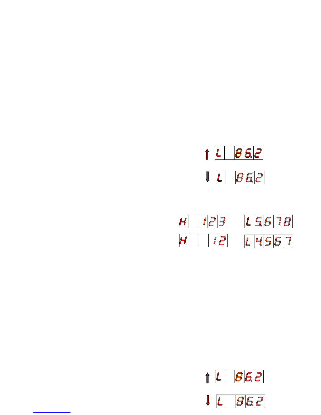
DISPLAY FORMAT
When the total value is between -9999 and 99999, it is shown
on the display with the letter ‘L’ in the auxiliary digit and with
the red led up and down arrows for positive and negative.
(positive)
(negative)
When the accumulated value exceeds from four digits, the
display alternates a 4 digit high order part (with the letter 'H'
in the auxiliary digit) and a 4 digit low order part (indicated by
the letter 'L' in the auxiliary digit).
(The switching between high and low order parts takes place
at a rate of approximately 2s each part).
3.5.3. Totalizer Option
The totalizer facility can be enabled and disabled by
software.
The totalizer counter shares the same input setup, count
mode and count direction as the process counter but
provides separate decimal point and scaling factor.
Each pulse received at the input increment or decrement
the process and total counters exactly, although the
display value may vary from one to another according to
individual scaling factor and reset operations.
The limits of the display are -9999999 and 99999999
(7 digits with minus sign or 8 digits).
The decimal point can be set to five decimal places.
The scaling factor is programmable between 0.00001
and 99999 as for the process counter.
The totalizer has no possibility to load a user selected
display value in a reset event.
3.5.4. Totalizer visualisation
The total value accumulated since the last reset will be
displayed in the format indicated hereafter, when
pressing on key TOTAL (if activated).
20
DISPLAY FORMAT
When the total value is between -9999 and 99999, it is shown
on the display with the letter ‘L’ in the auxiliary digit and with
the red led up and down arrows for positive and negative.
(positive)
(negative)
When the accumulated value exceeds from four digits, the
3.5.3. Totalizer Option
The totalizer facility can be enabled and disabled by
software.
The totalizer counter shares the same input setup, count
mode and count direction as the process counter but
provides separate decimal point and scaling factor.
Each pulse received at the input increment or decrement
the process and total counters exactly, although the
display value may vary from one to another according to
individual scaling factor and reset operations.
The limits of the display are -9999999 and 99999999
Page 21
21
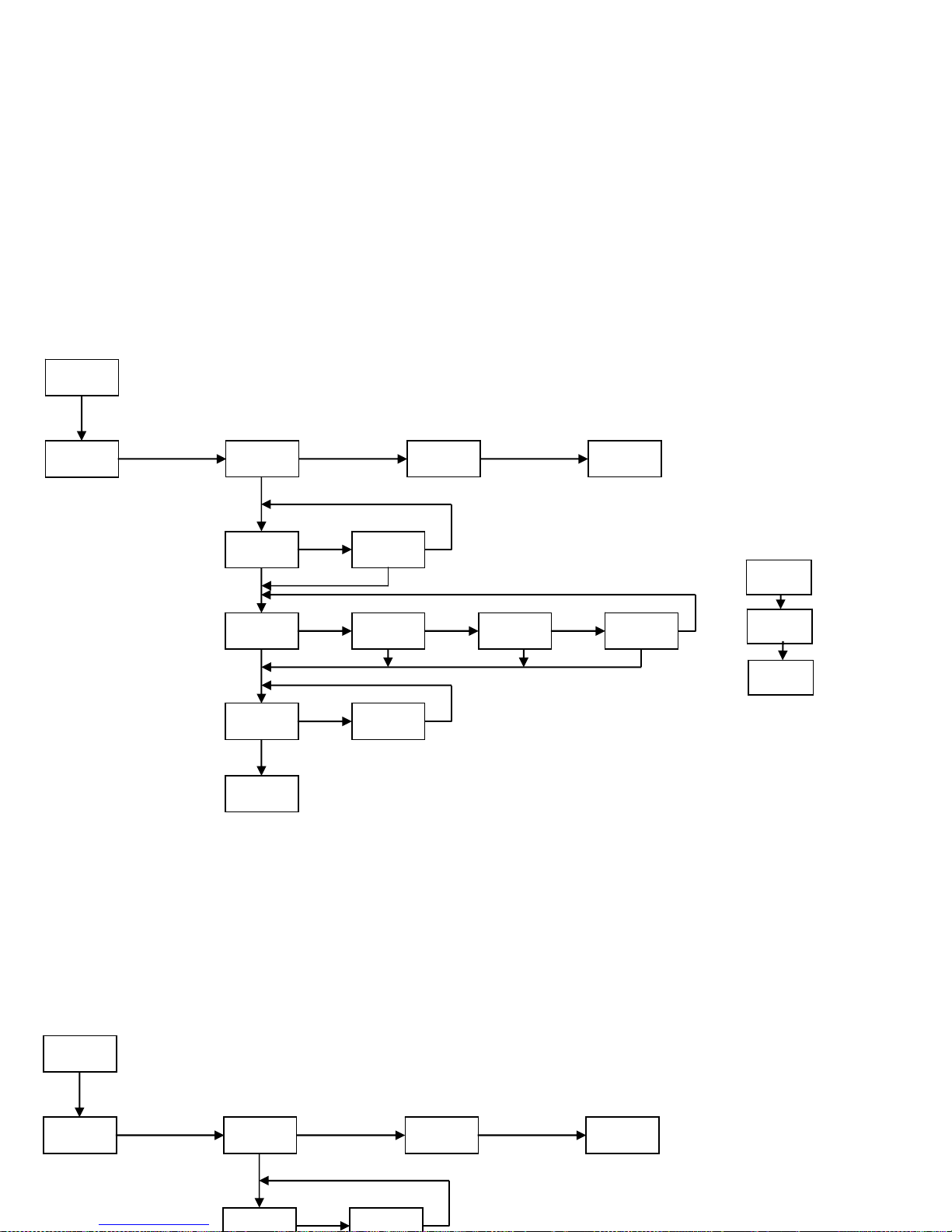
3.6. Programming diagram in MODE: CHRONOMETER
MODE
COUNT
CHRON FREC TAC
PrO
In A In A-B
H.H H.MM M.SS
DOWN UP
0.01 S
CndSP
OFFSEt
PrO
Programming diagram of the DISPLAY
in MODE: CHRONOMETER
3.6. Programming diagram in MODE: CHRONOMETER
MODE
COUNT
CHRON FREC TAC
In A In A-B
Programming diagram of the DISPLAY
in MODE: CHRONOMETER
Page 22
22
4. CHRONOMETER CONFIGURATION
INPUTS
The meter has two inputs for the START and STOP
signals that provide different types of time measurement
according to input setup (see page 23 "Start and Stop
Modes").
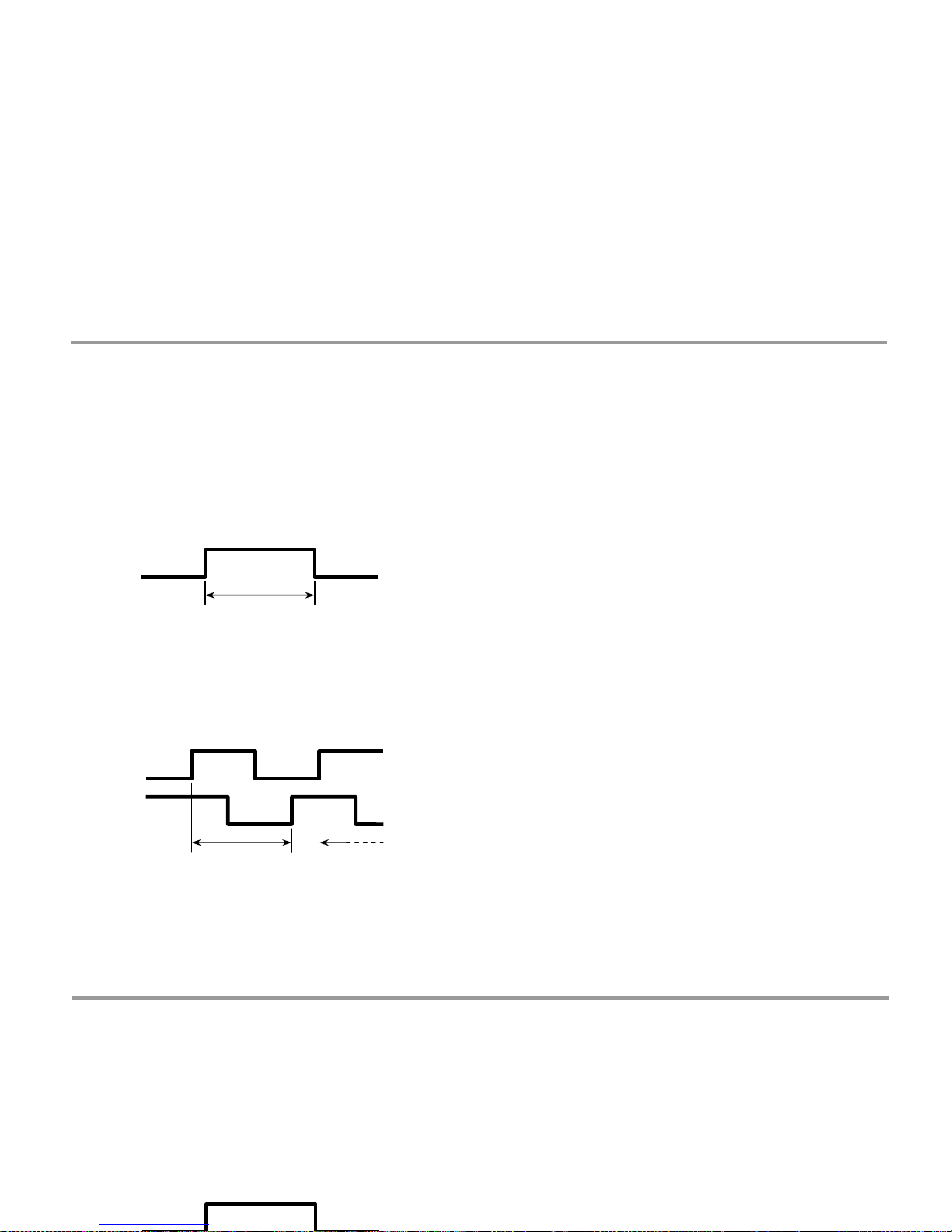
There are three selectable operating modes:
mode In-A, that allows to measure the width of a pulse,
and mode In-AB, that is used to measure the difference
between two signals
t
t
MEASURE
Time measurement is initiated on a rising edge of the
START input. This starts up an internal counter which is
controlled by a high precision crystal quartz clock.
The STOP signal suspends the internal count keeping the
value of the counter to the START of following time
measurement cycle.
The counter is missed to zero in a RESET operation.
In a disconnection from the power source, the instrument
saves the count value reached internally.
DISPLAY
The display can not be scaled, it only reads time in the units
selected according to the programmed time range.
The decimal point appears at a fixed position according to
time range.
OFFSET
An offset value can be programmed for example to count
down to zero from the preset time value.
The measured value, and the alarms if they exist, is
updated in each minimum unit of the selected magnitude.
Display refreshment: each 100ms.
4. CHRONOMETER CONFIGURATION
INPUTS
The meter has two inputs for the START and STOP
signals that provide different types of time measurement
according to input setup (see page 23 "Start and Stop
Modes").
There are three selectable operating modes:
mode In-A, that allows to measure the width of a pulse,
MEASURE
Time measurement is initiated on a rising edge of the
START input. This starts up an internal counter which is
controlled by a high precision crystal quartz clock.
The STOP signal suspends the internal count keeping the
value of the counter to the START of following time
measurement cycle.
The counter is missed to zero in a RESET operation.
In a disconnection from the power source, the instrument
Page 23
4.1. Input Setup
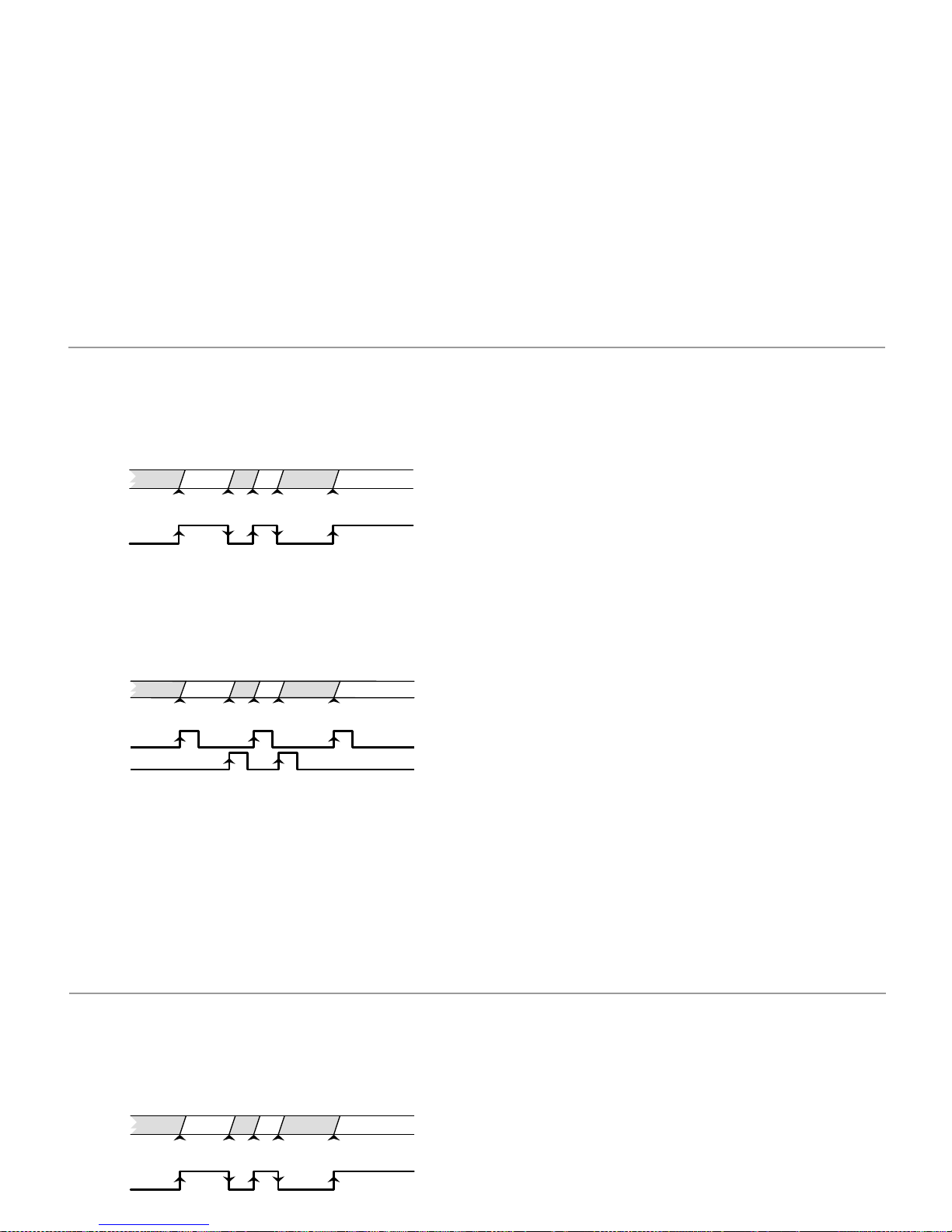
START AND STOP MODES
MODE In-A START on rising edge of input A.
STOP on falling edge of input A.
MODE In-AB START on rising edge if input A.
STOP on rising edge of input B.
start
display
input A
stop
start
stop
start
t1
t2
t3
UP or DOWN DIRECTION
uP : The meter acts as a stopwatch. It counts up the
time elapsed between the START and STOP signals.
When accumulated value exceeds from 99999, the
display reads OVER.
do : The meter acts as a timer. It counts down from a
user programmed offset to zero (a setpoint may be used
to perform any function at this point).
A reset operation sets the timer to the offset value; the
START signal initiates the timing count. When
accumulated value reaches 0, the next decrement makes
the display read UNDER.
TIME RANGE
There are four selectable time ranges:
H.H 9999.9 h (resolution 0.1 hours)
H.MM 999 h 59 m (resolution 1 minute)
M.SS 999 m 59 s (resolution 1 second)
0.01-S 999.99 s (resolution 0.01 second)
The decimal point appears in the position according to
the programmed time range.
(In a power failure, the meter saves the time value and
the internal count value).
start
display
input A
start
stop
start
t1
t2
t3
input B
23
4.1. Input Setup
START AND STOP MODES
MODE In-A START on rising edge of input A.
STOP on falling edge of input A.
start
display
input A
stop
start
stop
start
t1
t2
t3
UP or DOWN DIRECTION
uP : The meter acts as a stopwatch. It counts up the
time elapsed between the START and STOP signals.
When accumulated value exceeds from 99999, the
display reads OVER.
do : The meter acts as a timer. It counts down from a
user programmed offset to zero (a setpoint may be used
to perform any function at this point).
A reset operation sets the timer to the offset value; the
START signal initiates the timing count. When
accumulated value reaches 0, the next decrement makes
stop
Page 24

13211722232425262728261924
5. FREQUENCY METER / TACHOMETER CONFIGURATION
INPUTS
In frequency/tachometer mode both inputs of the meter
are used. The signal providing frequency/rate and count
information must be issued to the A input. A second
signal may be applied to the B input to control direction
of rotation or polarity of the signal.
MEASURE
The method of calculating rate is based in measuring
the period of the signal, that is, the time elapsed
between two consecutive rising edges. The period is
converted into a high precision frequency value and
scaled to read desired units.
DISPLAY
The meter allows the user to change some parameters
to fit the particular application needs, such as to reduce
or extend the number of signal cycles of each reading,
the time limit, the display rate and averaging (see
"Options of the Process Variable" in pages 29 and 30).
TOTALIZER
If enabled, the totalizer accumulates the number of
pulses received at the input providing two simultaneous
information for example flow rate and product quantity
for a given process.
DIRECTION OF ROTATION INDICATION
Direction sensing indication is a matter of simply setting
the totalizer to read UP/DOWN direction (modes PHASE
and dIrEC).
The direction of rotation is denoted by the LED's MAX
and MIN on the left of the display. LED MAX illuminates
when the totalizer counts in the up direction, so it can
be associated to a "positive" rate.
LED MIN illuminates when the totalizer counts down,
which may be associated to a "negative" rate.
A change in the polarity of rate is recognized when the
meter receives at least two consecutive pulses in the
opposite direction of the one of the previous pulses.
5. FREQUENCY METER / TACHOMETER CONFIGURATION
INPUTS
In frequency/tachometer mode both inputs of the meter
are used. The signal providing frequency/rate and count
information must be issued to the A input. A second
signal may be applied to the B input to control direction
of rotation or polarity of the signal.
MEASURE
The method of calculating rate is based in measuring
the period of the signal, that is, the time elapsed
TOTALIZER
If enabled, the totalizer accumulates the number of
pulses received at the input providing two simultaneous
information for example flow rate and product quantity
for a given process.
DIRECTION OF ROTATION INDICATION
Direction sensing indication is a matter of simply setting
the totalizer to read UP/DOWN direction (modes PHASE
and dIrEC).
Page 25
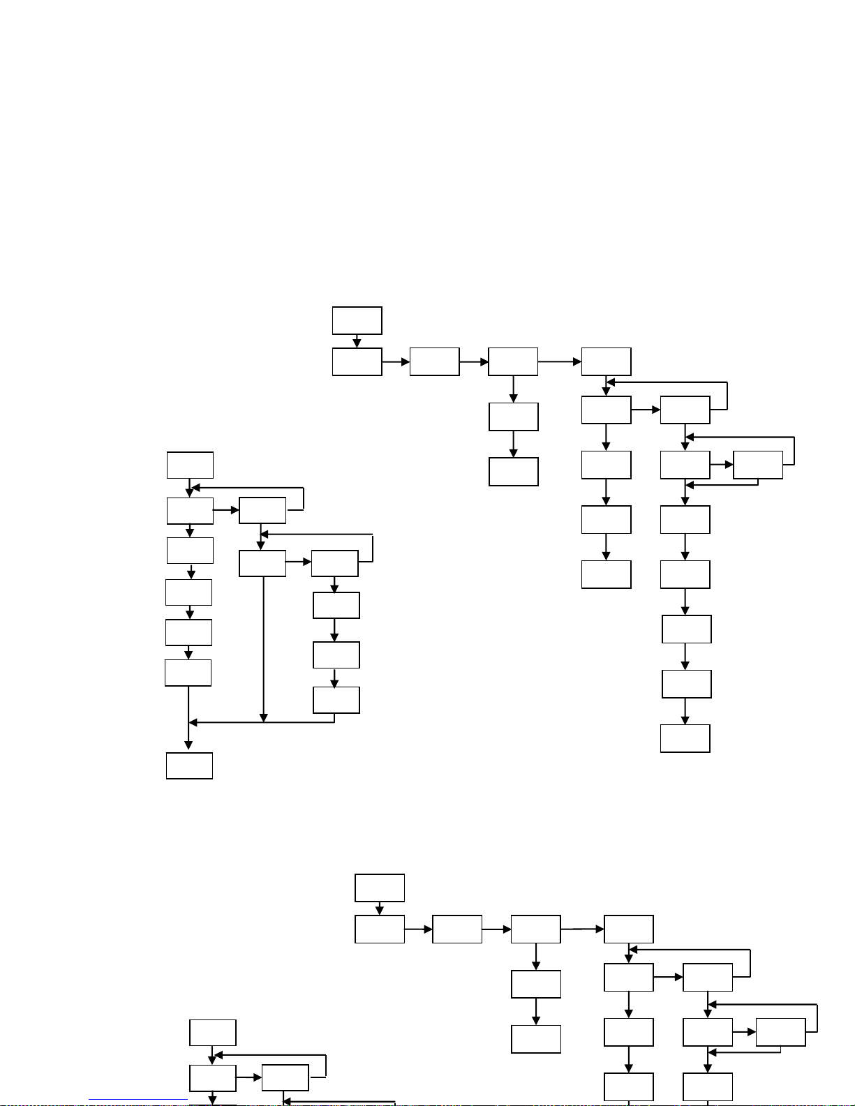
Programming diagram for MODE:
FRE
Q
UENCYMETER/ TACHOMETE
R
MODE
COUNT
CHRON FREC
T
AC
PrO
dCdiS
PrO dCFrE
dSP
rPM rAtE
PrO
inU PP
r
dCP
dir
dCciS
InP1
25
CndSP
PrOC
tOtAL
FACt
dCFAC
t.Lim
tAUE
nO
dCtOt
dCFAC
YES
FACtO
PrO
Programming diagram of the DISPLAY in
mode: FRE
Q
UENCYMETER / TACHOMETER
Programming diagram for MODE:
FRE
Q
UENCYMETER/ TACHOMETE
R
MODE
COUNT
CHRON FREC
T
AC
PrO
dCdiS
rPM rAtE
inU PP
r
dCP
dir
InP1
CndSP
PrOC
tOtAL
Programming diagram of the DISPLAY in
mode: FRE
Q
UENCYMETER / TACHOMETER
Page 26

5.1. Frequencymeter / Tachometer
CONFIGURATIONS
The different configurations allow measurement of
almost any process quantity based in frequency
calculation.
5.1.1. Frequencymeter
To use this instrument as frequency indicator, select
directly the frequencymeter input.
DECIMAL POINT
The only parameter to select in this input menu is the
position of the decimal point, which can be 0, 1 or 2.
The decimal point position determines the max. and min.
frequencies visible on display; with two decimals, max.
frequency will be 999.99Hz and min. frequency 0.01Hz,
with one decimal, max. frequency will be 9999.9Hz and
min. frequency 0.1Hz, and with no decimal, max.
frequency is limited according to the selected options
(see technical features in page 56) and min. frequency
will be 1Hz.
5.1.2. Tachometer for RPM
In this configuration the meter reads rotational rate in
revolutions per minute (RPM).
The tachometer is configured by entering the number of
pulses per revolution and the decimal point location.
PPR (PULSES PER REVOLUTION)
The PPR parameter is the actual number of pulses that a
sensor connected to a wheel gives to the input of the
meter in a rotation of the wheel.
The method of measurement is based in calculating the
time necessary for the system to produce a complete
rotation of the wheel, therefore, by default each reading
extends over the programmed number of pulses.
DECIMAL POINT
The decimal point location, in combination with a
suitable scale factor allows the display reading be
expressed into other units different from RPM if desired.
26
5.1. Frequencymeter / Tachometer
CONFIGURATIONS
The different configurations allow measurement of
almost any process quantity based in frequency
calculation.
5.1.1. Frequencymeter
5.1.2. Tachometer for RPM
In this configuration the meter reads rotational rate in
revolutions per minute (RPM).
The tachometer is configured by entering the number of
pulses per revolution and the decimal point location.
PPR (PULSES PER REVOLUTION)
Page 27

2827
5.1.3. Tachometer Rate
In this configuration the meter can be easily scaled to
read direction, speed, flow or time directly in the desired
units by entering only two parameters: Input Frequency
and Desired Display.
DIRECT OR REVERSED SCALING
Direct scaling. The relationship between frequency
and display is directly proportional, that is, the higher the
frequency, the greater the display. This will be the mode
to choose in most applications.
Reversed scaling. The relationship between frequency
and display is reversed, that is, the higher the frequency,
the lower the display. A typical application of this mode
is explained in the example of page 28.
The scaling procedure consists of entering a display
value corresponding to an input value. A straight line
plotted from this point to zero (input=0, display=0)
establishes a linear relationship between frequency and
display.
INPUT FREQUENCY
For scaling purposes, the input frequency value can be
programmed within all range of the display (the
frequency limits are given in page 57 of the present
manual).
The input frequency can be programmed with 0, 1 or 2
decimal places. The decimal point position has value, for
example, a frequency value of 200Hz can be
programmed as 200, 200.0 or 200.00
DESIRED DISPLAY
In this phase it is programmed the display value
corresponding to the programmed input frequency.
The decimal point can be located in any of the digits of
the display to help reading the display in the desired
units.
5.1.3. Tachometer Rate
In this configuration the meter can be easily scaled to
read direction, speed, flow or time directly in the desired
units by entering only two parameters: Input Frequency
and Desired Display.
DIRECT OR REVERSED SCALING
Direct scaling. The relationship between frequency
and display is directly proportional, that is, the higher the
frequency, the greater the display. This will be the mode
to choose in most applications.
The scaling procedure consists of entering a display
value corresponding to an input value. A straight line
plotted from this point to zero (input=0, display=0)
establishes a linear relationship between frequency and
display.
INPUT FREQUENCY
For scaling purposes, the input frequency value can be
programmed within all range of the display (the
frequency limits are given in page 57 of the present
manual).
The input frequency can be programmed with 0, 1 or 2
Page 28

EXAMPLE OF SCALING IN RATE MODE
Loaves of bread are transported in a conveyor belt and
introduced in a continuous baking oven. The belt is attached
to a turning shaft of 20cms that gives 6 pulses per revolution.
The average time necessary for a loaf to be baked is 15min
and 30s and it has been determined that, to achieve this time,
the rate of the turning shaft must be kept to 300rpm.
This example allows exposing some capabilities of the rate
meter configuration.
The rate of the turning shaft is 300 revolutions per minute,
which is equal to 5 revolutions per second.
If the turning shaft makes 5 complete revolutions in one
second and each revolution drives out 6 pulses, the total
number of pulses per second is 30. The input frequency is
then 30Hz.
Rate of the conveyor belt (m/s)
The rate of the conveyor belt at the specified frequency is:
rpm * π * diameter = 300 * π * 20 = 18849.6 cm/min which
is in m/s, 3.142m/s.
PARAMETERS TO PROGRAM:
RATE MODE: DIRECT
INPUT FREQUENCY: 30
DESIRED DISPLAY: 03142
DECIMAL POINT: 03.142 (m/s)
Baking Time (min)
It is required to monitor the baking time knowing that, at the
specified frequency of 30Hz, the time taken for each loaf to be
baked is 15min 30s.
When rate (and frequency) grows, the baking time is reduced
proportionally. The rate meter must then be programmed for
reverse mode.
PARAMETERS TO PROGRAM:
RATE MODE: INVERSE
INPUT FREQUENCY: 30
DESIRED DISPLAY: 00155
DECIMAL POINT: 0015.5 (min)
The time values must be programmed in decimal notation.
In the preceding example, a baking time of 15min 30s has been
introduced as a display value of 15.5 (15 minutes and a half).
Daily Production (loaves/day)
It has been determined that, in the specified conditions, the
bread loaves are baked at an average of 10 loaves per minute.
The baking oven works 12 hour per day and it is required to
monitor the production of loaves per day.
Ten loaves per minute is equivalent to 10x60=600 loaves per
hour.
At a frequency of 30Hz, the daily production is 600x24=14400
loaves/day.
PARAMETERS TO PROGRAM:
RATE MODE: DIRECT
INPUT FREQUENCY: 30
DESIRED DISPLAY: 14400
DECIMAL POINT: NO
28
EXAMPLE OF SCALING IN RATE MODE
Loaves of bread are transported in a conveyor belt and
introduced in a continuous baking oven. The belt is attached
to a turning shaft of 20cms that gives 6 pulses per revolution.
The average time necessary for a loaf to be baked is 15min
and 30s and it has been determined that, to achieve this time,
the rate of the turning shaft must be kept to 300rpm.
This example allows exposing some capabilities of the rate
meter configuration.
The rate of the turning shaft is 300 revolutions per minute,
which is equal to 5 revolutions per second.
Baking Time (min)
It is required to monitor the baking time knowing that, at the
specified frequency of 30Hz, the time taken for each loaf to be
baked is 15min 30s.
When rate (and frequency) grows, the baking time is reduced
proportionally. The rate meter must then be programmed for
reverse mode.
PARAMETERS TO PROGRAM:
RATE MODE: INVERSE
INPUT FREQUENCY: 30
DESIRED DISPLAY: 00155
DECIMAL POINT: 0015.5 (min)
The time values must be programmed in decimal notation.
Page 29
5.2. Display Setup
5.2.1. Options of the Process Variable
The menu ProC in the module CndSP contains various parameters for scaling and filtering the display -Scale Factor, Max
and Min Times, Averaging-.
SCALE FACTOR
The scale factor is programmable between 0.0001 and 9999 and multiplicities or divides depending on if it is higher or lower
than 1.
For example, it can be used to change display units, rpm instead of rps.
TIME LIMIT
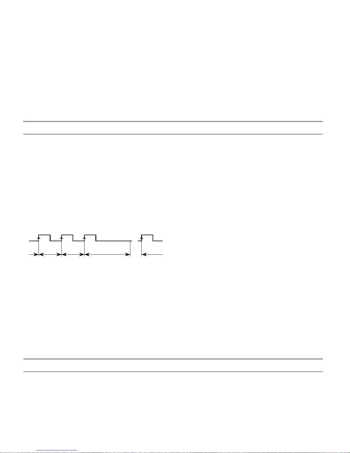
The time limit, programmable from 1 to 99 seconds, is the amount of time that the meter waits for at least one pulse is
produced at the input before it is considered to be zero.
The time limit is initialized at the reception of each input pulse. If no more pulses are detected before the
time limit runs out, the display is forced to zero.
0.............. 0.............. 0.................... t límite
0............. ......
display=0
Decreasing the limit time makes the instrument respond more quickly to the zero condition when the system stops.
Nevertheless, this reduction also will cut the lowest frequencies (for example: with a time limit of 10s, it would be
impossible to see frequencies under 0.1Hz and with a time of 1s, frequencies under 1Hz).
29
5.2. Display Setup
5.2.1. Options of the Process Variable
The menu ProC in the module CndSP contains various parameters for scaling and filtering the display -Scale Factor, Max
and Min Times, Averaging-.
SCALE FACTOR
The scale factor is programmable between 0.0001 and 9999 and multiplicities or divides depending on if it is higher or
lower than 1.
For example, it can be used to change display units, rpm instead of rps.
TIME LIMIT
The time limit, programmable from 1 to 99 seconds, is the amount of time that the meter waits for at least one pulse is
produced at the input before it is considered to be zero.
Page 30

AVERAGE TIME
The average time is a time interval in seconds during
which all readings calculated from the input are
averaged.
The average time is programmable from 0 to 9.9
seconds.
To disable this feature program 0.
When the display presents unwanted variations, due
to that the input signal is not regular, the
programming of the average time for a larger value
may help stabilize the display.
The average time can be calculated for a desired
number of readings knowing the signal frequency.
Example: With a setup of 0.1s, if the input signal
frequency is of approx. 10Hz or less, the meter will
only take one reading per each 0.1s making no
average. With an input signal of approx. 100Hz, the
meter will be able to collect and average about 10
readings in 0.1s. If the input signal is of approx.
1000Hz, the display will read out the average of
about 100 readings.
30
IMPORTANT: Direction sensing indication is achieved
by selecting one of the bidirectional count modes
PHASE or dIrEC.
"Positive sign" indication occurs when the pulses applied to
the instrument increase the counter while "negative sign"
indication occurs when the input pulses decrement the
counter.
A change in the polarity of rate is recognized when the meter
receives at least two consecutive pulses in the opposite
direction of the one of the previous pulses.
DECIMAL POINT
The decimal point indication helps to read the display in the
desired engineering units.
The decimal point has not real value, that is the digits to the
right of the decimal point are not actually decimals. To read
values with resolution to the desired decimal places is
achieved by a combination of decimal point and scaling
factor.
SCALE FACTOR
The scale factor is programmable from 0.0001 to 99999.
Individual decimal point location makes possible to program
any value within this range independently from the decimal
point of the display. Any number below 1 acts like a divisor
while a number above 1 acts like a multiplier.
AVERAGE TIME
The average time is a time interval in seconds during
which all readings calculated from the input are
averaged.
The average time is programmable from 0 to 9.9
seconds.
To disable this feature program 0.
When the display presents unwanted variations, due
to that the input signal is not regular, the
programming of the average time for a larger value
may help stabilize the display.
IMPORTANT: Direction sensing indication is achieved
by selecting one of the bidirectional count modes
PHASE or dIrEC.
"Positive sign" indication occurs when the pulses applied to
the instrument increase the counter while "negative sign"
indication occurs when the input pulses decrement the
counter.
A change in the polarity of rate is recognized when the meter
receives at least two consecutive pulses in the opposite
direction of the one of the previous pulses.
DECIMAL POINT
The decimal point indication helps to read the display in the
desired engineering units.
Page 31

RESET KEY
The RESET key allows, in Tachometer mode,
setting the Max and Min memories to the current
value.
To set the MAX or MIN value to the current value,
the value you want to reset must be showed on
display and pressing on the reset key will erase this
value.
To reset the totalizer it is necessary to recall the
TOTAL variable on display pressing TOTAL key and
then press RESET.
Clear to zero the variable present on display is
carried out when releasing the RESET key; being
then reinitiated the count, in counter mode or
chronometer, from zero or offset.
The RESET key will not operate if in the
program lock-out routine its corresponding
step is activated.
5.2.2 TOTAL, MAX and MIN Visualization
In tachometer mode one push on the MAX/ MIN
key shows, when activated, the total value in the
programmed color; next push shows the peak value
with the flashing led MAX indicator; next push shows
the valley value with the flashing led MIN indicator;
another push brings us back to current value
indication.
31
RESET KEY
The RESET key allows, in Tachometer mode,
setting the Max and Min memories to the current
value.
To set the MAX or MIN value to the current value,
the value you want to reset must be showed on
display and pressing on the reset key will erase this
value.
To reset the totalizer it is necessary to recall the
TOTAL variable on display pressing TOTAL key and
then press RESET.
Clear to zero the variable present on display is
carried out when releasing the RESET key; being
Page 32
32
6 – LOGIC FUNCTIONS
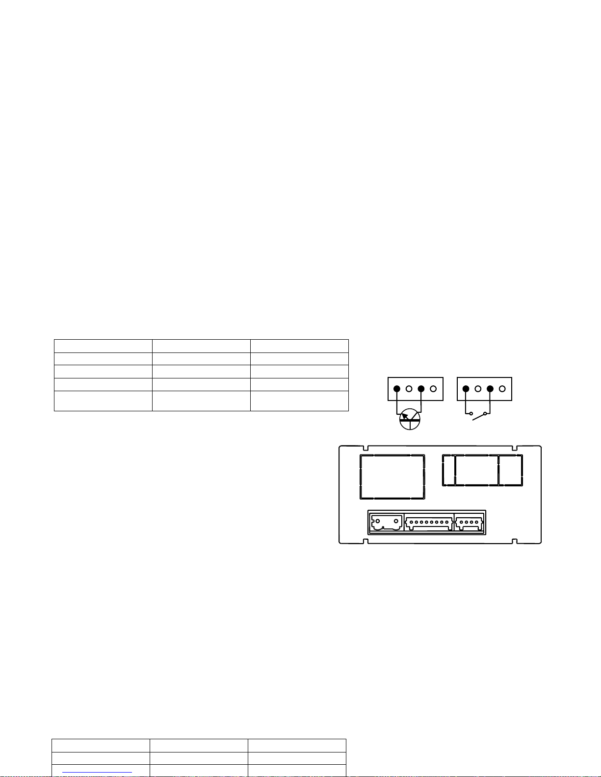
The rear connector CN3 provides 3 user programmable opto-coupled inputs that can be operated from external contacts
or logic levels supplied by an electronic system. Three different functions may be added to the functions available from
the front-panel keys. Each function is associated to one pin (PIN 2, PIN 3, PIN 4) and is activated by applying a falling
edge or a low level pulse to the corresponding pin with respect to common (PIN 1).
Each pin can be assigned one of the 13 functions listed on the following pages.
• Factory configuration
Functions associated to Connector CN3 in factory configuration are: OFFSET, RESET and RESET TOTALIZER.
CN3: FACTORY CONFIGURATION
PIN (INPUT) Function Number
PIN 1 COMMON
PIN 2 (INP-1) OFFSET Function nº 1
PIN 3 (INP-2) RESET Function nº 2
PIN 4 (INP-3) RESET TOTALIZER Function nº 6
Logic functions diagram
1 2 3 4 1 2 3 4
CN3
1 2 3 4
The external electronics applied to the CN3 connector must
be capable of withstanding 40 V and 20 mA present at all
terminals with respect to COMMON. In order to guarantee
the electromagnetic compatibility, please refer to the
instructions given on page 9.
6 – LOGIC FUNCTIONS
The rear connector CN3 provides 3 user programmable opto-coupled inputs that can be operated from external contacts
or logic levels supplied by an electronic system. Three different functions may be added to the functions available from
the front-panel keys. Each function is associated to one pin (PIN 2, PIN 3, PIN 4) and is activated by applying a falling
edge or a low level pulse to the corresponding pin with respect to common (PIN 1).
Each pin can be assigned one of the 13 functions listed on the following pages.
• Factory configuration
Functions associated to Connector CN3 in factory configuration are: OFFSET, RESET and RESET TOTALIZER.
CN3: FACTORY CONFIGURATION
PIN (INPUT) Function Number
PIN 1 COMMON
PIN 2 (INP-1) OFFSET Function nº 1
Logic functions diagram
1 2 3 4 1 2 3 4
Page 33
33
Nº Function Description Activation by
0 Deactivated None None
1 OFFSET Adds the current display value to the offset memory and sets the display to
zero.
Falling edge
2 RESET Sets to zero the partial counter value (Proc) Falling edge
3 MAX Displays the peak value. (MÁX.) In Tachometer mode. Low level
4 MIN Displays the valley value. (MÍN) In Tachometer mode. Low level
5 RESET MAX/ MIN Clears the peak or valley readings (the one shown in the display). Falling edge
6 RESET TOTALIZER Sets the TOTALIZER to zero. Low level
7 PRINT PROCESS Sends the partial counter value (Proc) to printer Falling edge
8 PRINT TOTAL Sends the total value to printer Falling edge
9 PRINT OFFSET Sends the offset value to printer Falling edge
10 ASCII Sends the last four digits to a MICRA-S. By holding the input to a low level,
transmission takes place every second
Falling edge / Low
level
11 BRIGHTNESS Change the display brightness from Hi to Low Low level
12 SETPOINT VALUE Displays the selected setpoint value (see diagram next page) Low level
13 False Setpoints Simulates that the instrument has a four setpoints option installed Low level
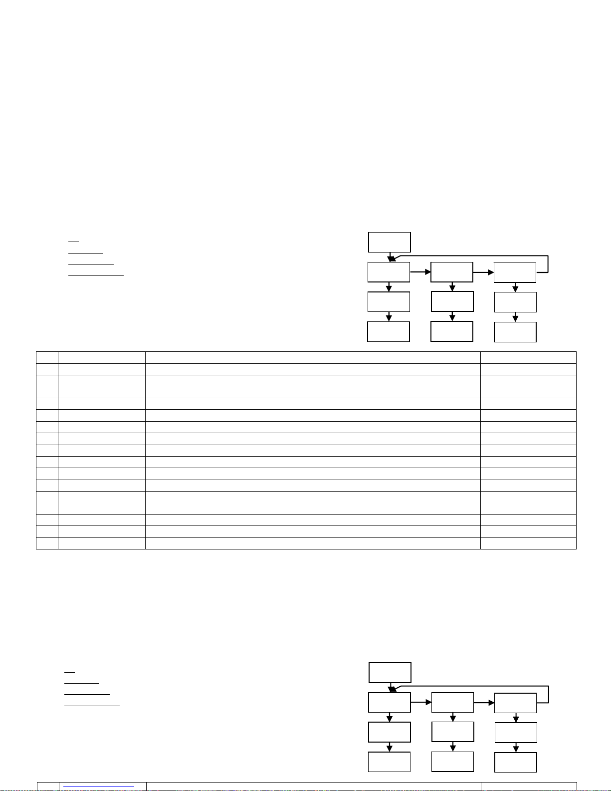
6.1.1 – Logic functions diagram
6.1 – Programmable functions table
• Nº: Number to select the function via software.
• Function: function name.
• Description: Function operation and characteristics.
• Activation by :
Falling edge: the function is activated applying a falling edge
to the corresponding pin with respect to common.
Low level: The function will remain activated as long as the
corresponding pin is held at a low level.
LoGIn
Inp-1
88
-Pro-
Inp-2
Inp-3
88
-Pro-
88
-Pro-
6.1.1 – Logic functions diagram
6.1 – Programmable functions table
• Nº: Number to select the function via software.
• Function: function name.
• Description: Function operation and characteristics.
• Activation by :
Falling edge: the function is activated applying a falling edge
to the corresponding pin with respect to common.
Low level: The function will remain activated as long as the
corresponding pin is held at a low level.
LoGIn
Inp-1
88
-Pro-
Inp-2
Inp-3
88
-Pro-
88
-Pro-
Page 34
3234
6.2 – Program of functions
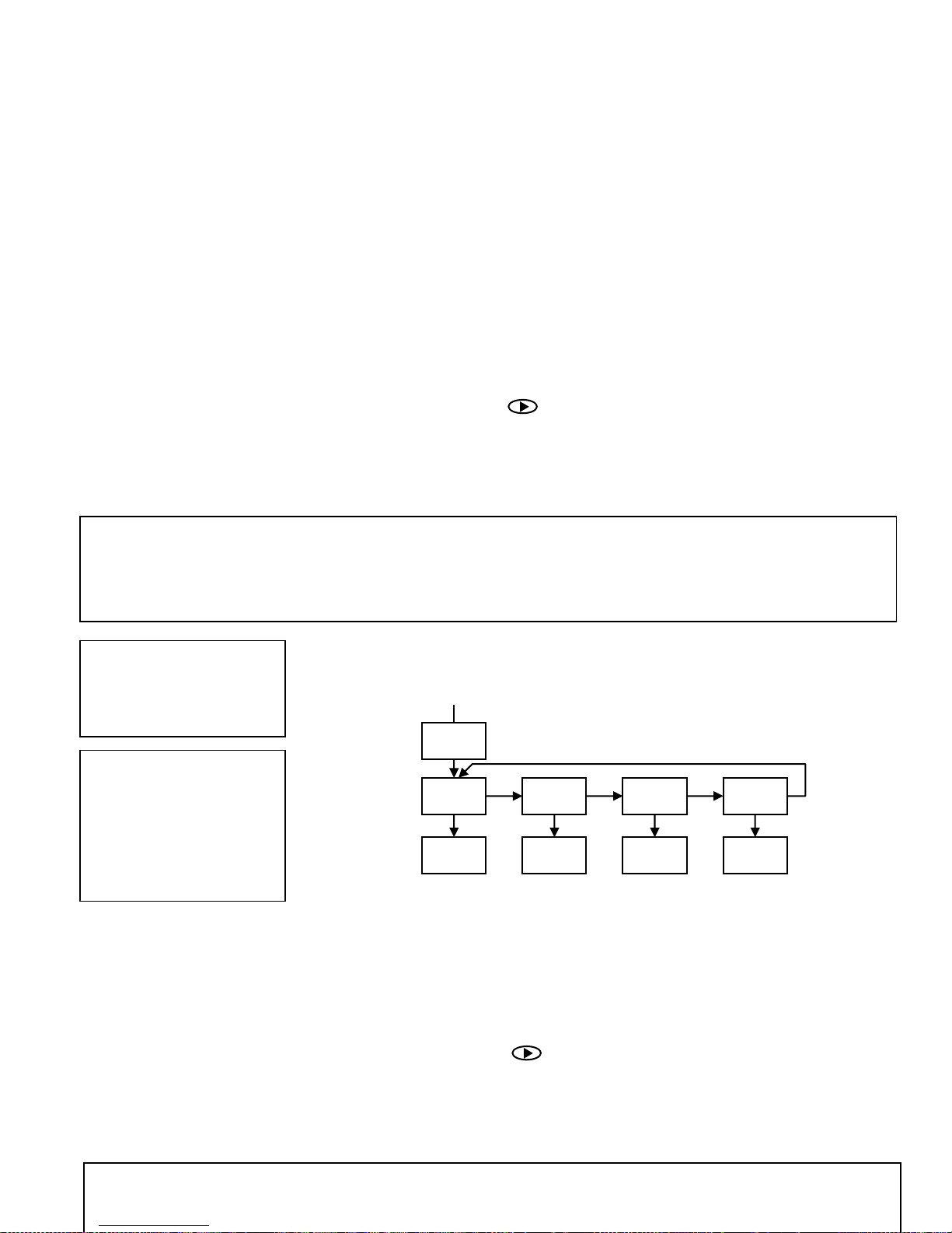
Once the user has accessed the menu of logic functions configuration, he can
select, by pressing the
key, a function among those of the table.
If the user selects any of the logic functions 7, 8 or 9, the instrument will display
any of these 2 messages. The second, when activated the corresponding function,
will add to the corresponding value sent to the printer the order to print date
and time.
0 to 13
t-off t-on-
If the selected function is number 13 and any of the 2RE, 4RE, 4OP, 4OPP options is
installed, the user will have to choose one of the two or four setpoints available depending
on the option, which will be the value displayed by the instrument when this function is
activated.
Example: MICRA-D with value of 1234.5
Message in Hexadecimal sent from the MICRA-D RS4 output when logic function 7 is activated.
With
t-off
the chain of characters is: 0x18, 0x23, ”01”, 0x0D, “NET: +1234.5”, 0x0D
With
t-on-
the chain will be: 0x18, 0x23, ”01”, 0x0D, “NET: +1234.5”, 0x0D, 0x18, 0x4A, 0x06, 0x18, 0x48
T
he MICRA-D has to be programmed to work under protocol ASCII (Prt1) y (dLY 1). See Page 49
Example ticket without date
using printer
#01
NET: +1234.5
Example ticket without date
using printer
#01
NET: +1234.5
Time 15:07 Date 11
/04/
05
12
SEt 1 SEt 2 SEt 3 SEt 4
-Pro-
-Pro- -Pro- -Pro-
6.2 – Program of functions
Once the user has accessed the menu of logic functions configuration, he can
select, by pressing the
key, a function among those of the table.
If the user selects any of the logic functions 7, 8 or 9, the instrument will display
any of these 2 messages. The second, when activated the corresponding function,
will add to the corresponding value sent to the printer the order to print date
and time.
0 to 13
t-off t-on-
Example: MICRA-D with value of 1234.5
Message in Hexadecimal sent from the MICRA-D RS4 output when logic function 7 is activated.
With
t-off
the chain of characters is: 0x18, 0x23, ”01”, 0x0D, “NET: +1234.5”, 0x0D
Page 35

35
7. PROGRAM PARAMETERS AND KEYBOARD FUNCTIONS LOCK-OUT
The instrument is supplied with all software programming parameters accessible to operator's modifications. After
completing the software configuration, it is recommended to protect configuration settings by the following steps:
1. Lockout programming parameters to prevent from accidental or unauthorized modifications.
2. Lockout keyboard functions to prevent from accidental or unauthorized modifications.
3. There are two modes to lock-out the program parameters; total or selective. If some parts of the program have to be
adjusted at a later time, make a selective lock. If you don’t need to make changes, make a total lock.
4. The access to the lockout routine is allowed by entering a safety code. At factory this code is set to 0000. We
recommend changing this code, to write it down and keep in a safe place.
TOTAL LOCKOUT
The access to the programming routines to read data is allowed even if all parameters are locked out totLC=1, but it will
not be possible to enter or modify data. In this case, when entering in the programming mode, the display shows the
indication "-dAtA-".
SELECTIVE LOCKOUT
When only some parameters are locked out, all configuration data can be read but only non-protected parameters can
be modified. In such case, when entering in the programming mode, the display shows the indication -Pro-.
7. PROGRAM PARAMETERS AND KEYBOARD FUNCTIONS LOCK-OUT
The instrument is supplied with all software programming parameters accessible to operator's modifications. After
completing the software configuration, it is recommended to protect configuration settings by the following steps:
1. Lockout programming parameters to prevent from accidental or unauthorized modifications.
2. Lockout keyboard functions to prevent from accidental or unauthorized modifications.
3. There are two modes to lock-out the program parameters; total or selective. If some parts of the program have to be
adjusted at a later time, make a selective lock. If you don’t need to make changes, make a total lock.
4. The access to the lockout routine is allowed by entering a safety code. At factory this code is set to 0000. We
Page 36

36
Menus or submenus that can be locked out are:
• Setpoint 1 configuration (SEt 1).
• Setpoint 2 configuration (SEt 2).
• Setpoint 3 configuration (SEt 3).
• Setpoint 4 configuration (SEt 4).
• Input configuration (InPut).
• Display (dsp)
• Analog output configuration (Anout).
• Serial output configuration (rSout).
• Logic inputs configuration (LoGIn).
• Lock-out of the reset key, not of the logic function.
• Offset value configuration
• Direct access to the Setpoints value configuration (SEtVAL).
The first four and “SEtVAL” only appear if the corresponding option 2RE, 4RE, 4OP ó 4OPP has been installed, “Anout” will appear
when any of the NMA or NMV options are installed, and “rSout” when any of the RS2 or RS4 options are installed.
7.1 – Security menu diagram
The following figure shows the security menu. In this menu is configured the programming lockout. The access to this menu is
accomplished from the run mode by pressing the
key during 3 seconds, until the "CodE" indication appears.
The instrument is shipped from factory with the following default code: "0000". Once entered this code, the “LISt” indication will
appear, from which we will enter in the parameters lockout. Acceding to the "CHAnG" menu will allow us to enter a personal code,
that we have to write down and keep in a safe place (Do not count on your memory). This personal code makes the default
code useless.
If an incorrect code is entered, the instrument will return automatically to the run mode.
Total lockout programming is achieved changing to 1 the “totLC" variable, changing it to 0, will lead to the selective lockout of the
programming variables. Programming each one of the parameters to 1 will active the lockout, if they are set to 0 programming will
be accessible. Though the programming is locked out, it remains possible to visualise the current programming.
The "StorE" indication informs that the modifications effectuated have been stored correctly.
Menus or submenus that can be locked out are:
• Setpoint 1 configuration (SEt 1).
• Setpoint 2 configuration (SEt 2).
• Setpoint 3 configuration (SEt 3).
• Setpoint 4 configuration (SEt 4).
• Input configuration (InPut).
• Display (dsp)
• Analog output configuration (Anout).
• Serial output configuration (rSout).
• Logic inputs configuration (LoGIn).
• Lock-out of the reset key, not of the logic function.
• Offset value configuration
• Direct access to the Setpoints value configuration (SEtVAL).
Page 37
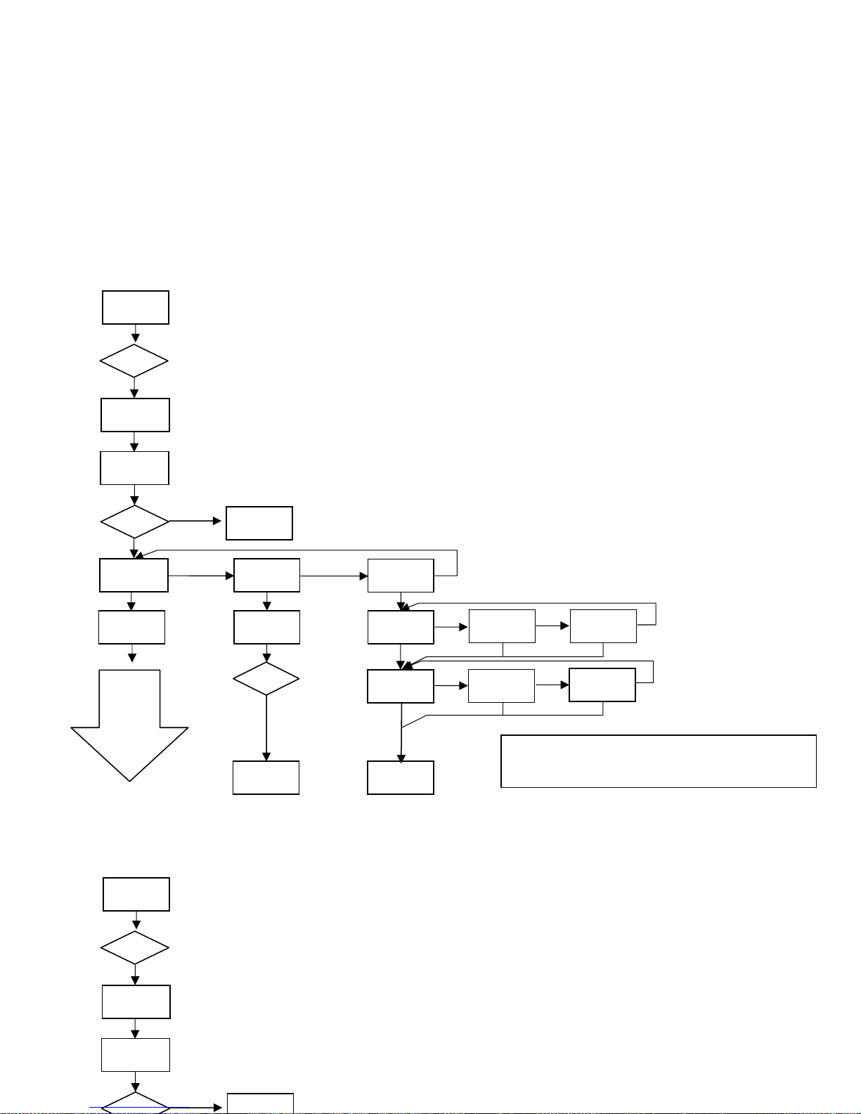
Pro
(Green)
Pro
(Yellow)
Pro
(Red)
totLC
(bloq. Total)
--- -
Run
(Red)
Run
(Green)
Run
(Yellow)
CHANG
CoLor
LISt
(list param)
=Code?
8888
Enter > 3 s
CodE
RUN
RUN
8888
Enter > 3 s
CodE
RUN
RUN
37
StorE StorE
Si
≠----?
Pag 38
Note: the color selection of the alarms is
made in the setpoints menu (Page 44)
Page 38
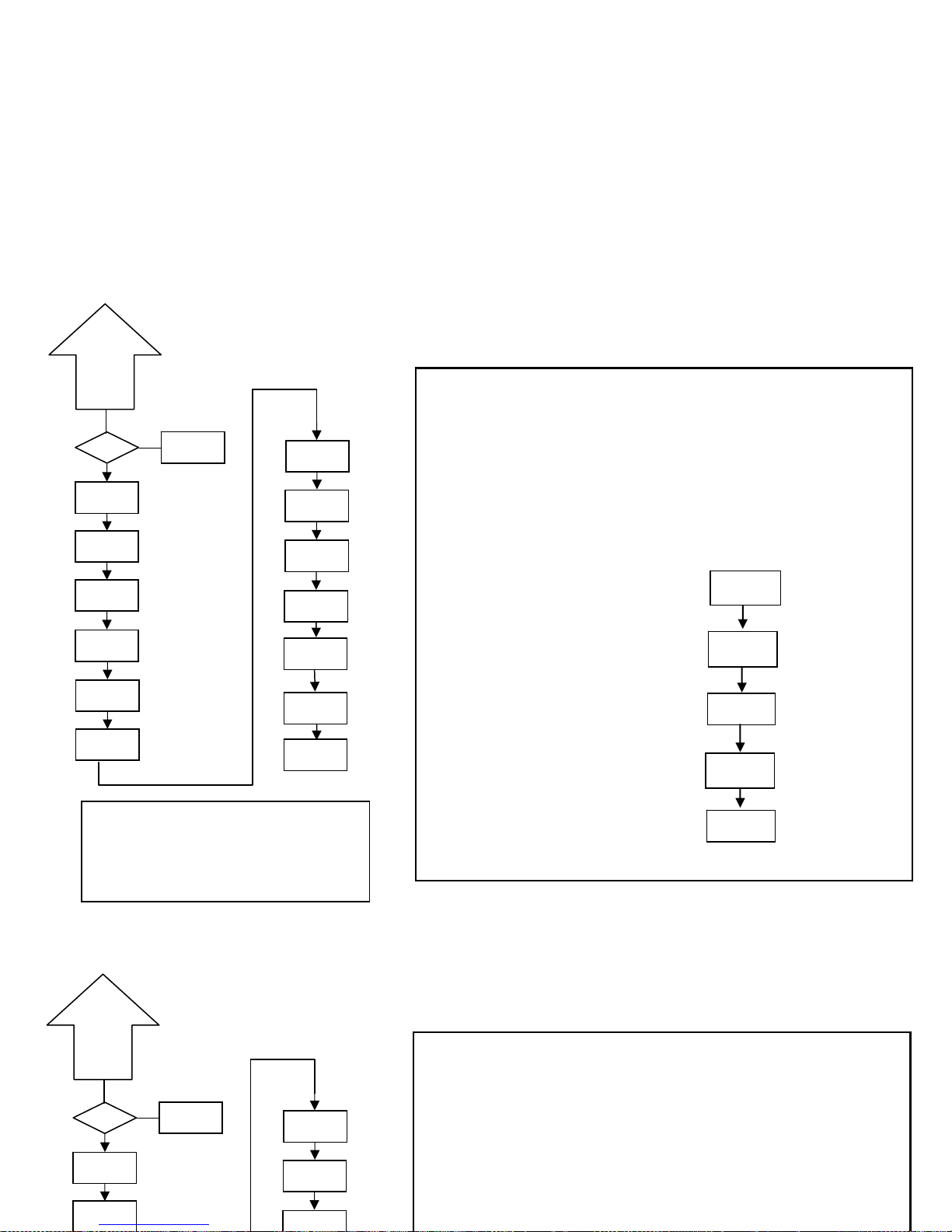
38
0 allows its programming
1 locks the access to programming
* Only appear if the corresponding
options have been installed
*
*
StorE
InPut
d
SP
SEt 1
SEt 2
SEt 3
SEt 4
Anout
rSout
LoGIn
rESEt
StVAL
Si
=Code
StorE
Pag. 37
*
*
*
*
oFFSEt
*
8. RESTORATION OF FACTORY CONFIGURATION
RUN
-Pro-
00
LoAdin
StorE
Enter < 3s
Enter > 3s
Introduce code 74
Enter < 3s
*
*
SEt 1
SEt 2
Anout
rSout
Si
=Code
StorE
Pag. 37
*
*
Following the herewith diagram, factory configuration can be restored:
CnInP = - 6- , Encoder /TTL, Count, uP-do, PHASE.
CndSP = ProC without decimal; offset=0, multiplying factor= 1, without decimal;
Tot YES, without decimal, multiplying factor= 1, without decimal ;
Setpoint 1= on, ProC=1000, mode=1, latch, alarm= red,
Tot=1000, mode=1, latch, alarm= red,
Setpoint 2, 3, 4 same as Sepoint 1 but setpoint value to 2000, 3000 and 4000.
Anout = outHI= 1000, outLo=0000
rSout = Baud 9600, Adr= 01, trans= Prt 2
LoGIn = InP-1=1, InP-2=2, InP-3=6
8. RESTORATION OF FACTORY CONFIGURATION
Following the herewith diagram, factory configuration can be restored:
CnInP = - 6- , Encoder /TTL, Count, uP-do, PHASE.
CndSP = ProC without decimal; offset=0, multiplying factor= 1, without decimal;
Tot YES, without decimal, multiplying factor= 1, without decimal ;
Setpoint 1= on, ProC=1000, mode=1, latch, alarm= red,
Tot=1000, mode=1, latch, alarm= red,
Setpoint 2, 3, 4 same as Sepoint 1 but setpoint value to 2000, 3000 and 4000.
Anout = outHI= 1000, outLo=0000
rSout = Baud 9600, Adr= 01, trans= Prt 2
LoGIn = InP-1=1, InP-2=2, InP-3=6
Page 39

39
9. OUTPUT OPTIONS
Optionally, model MICRA-D can incorporate one or several output options for control or communication:
Communication options
RS2 Serial RS232C
RS4 Serial RS485
Control options
NMA Analog 4-20 mA
NMV Analog 0-10 V
2RE 2 Relays SPDT 8 A
4RE 4 Relays SPST 5 A
4OP 4 NPN outputs
4OPP 4 PNP outputs
All mentioned options are optoisolated with respect to input signal and power supply.
The output cards are easily installed on the meter’s main board by means of plug-in connectors and each one activates its own
programming modules that provides complete software configuration.
Additional capabilities of the unit with output options:
• Control and processing of limit values via ON/OFF logic outputs or proportional output (4-20mA, 0-10V).
• Communication, data transmission and remote programming via serial interface.
For more detailed information on characteristics and mounting, please refer to the specific manual supplied with each option.
9. OUTPUT OPTIONS
Optionally, model MICRA-D can incorporate one or several output options for control or communication:
Communication options
RS2 Serial RS232C
RS4 Serial RS485
Control options
NMA Analog 4-20 mA
NMV Analog 0-10 V
2RE 2 Relays SPDT 8 A
4RE 4 Relays SPST 5 A
Page 40
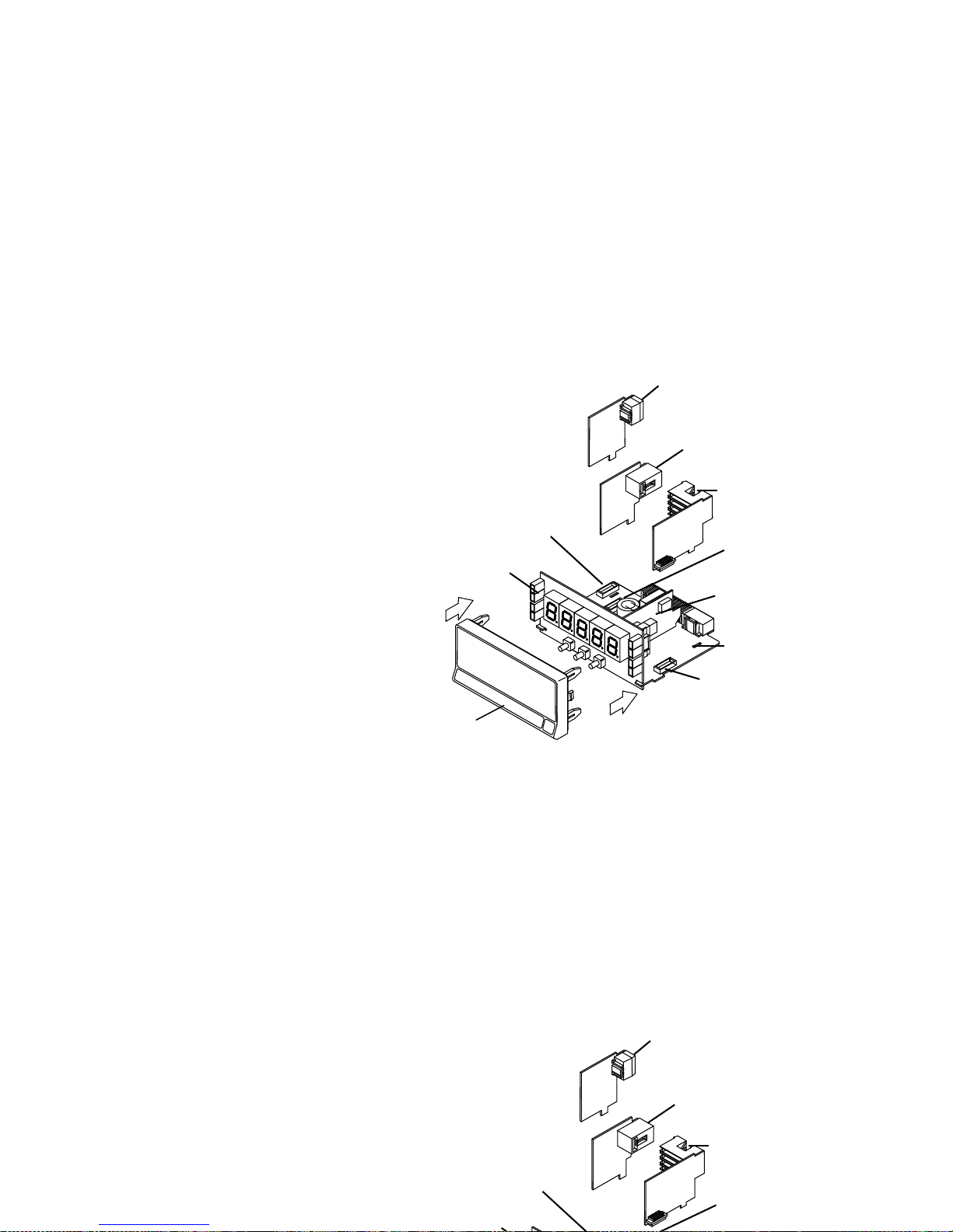
FRONT PANEL
COVER
ANALOGUE
OUTPUT
OPTION
(NMA/ NMV
MAIN BOARD
RS232C/ RS485
OUTPUT
DISPLAY
RELAYS/ OPTO
OUTPUT
POWER FILTER
CIRCUIT
M3
CONNECTOR FOR
ANALOGUE OUTPUT
M1
CONNECTOR
RELAYS OUTPUT
M2
CONNECTOR FOR RS
OUTPUT
ANALOGUE
OUTPUT
OPTION
(NMA/ NMV
RS232C/ RS485
OUTPUT
DISPLAY
RELAYS/ OPTO
OUTPUT
M3
CONNECTOR FOR
ANALOGUE OUTPUT
M2
CONNECTOR FOR RS
OUTPUT
40
The following figure shows the location
of the different outputs options.
The 2RE, 4RE, 4OP y 4OPP options
are alternative and only one of them
can be placed into the connector M1.
The RS2 and RS4 options are also
alternative and only one of them can
be placed into the connector M2
The NMA or NMV option is placed into
the connector M3.
Up to three output options can be
present at the same time and operate
simultaneously:
• One analog (ref. NMA or ref
NMV)
• One RS232C (ref. RS2) or RS485
(ref. RS4).
• One 2 relays (ref. 2RE) or 4 relays
(ref. 4RE) or 4 NPN (ref. 4OP) or
4 PNP (ref. 4OPP) outputs.
The following figure shows the location
of the different outputs options.
The 2RE, 4RE, 4OP y 4OPP options
are alternative and only one of them
can be placed into the connector M1.
The RS2 and RS4 options are also
alternative and only one of them can
be placed into the connector M2
The NMA or NMV option is placed into
the connector M3.
Page 41

41
9.1 – Setpoints output
9.1.1 – Introduction
An option of 2 or 4 SETPOINTS, programmable within the full display range, can be incorporated to the unit thus providing
alarm and control capabilities by means of individual LED indicators and relay or transistor outputs. All the setpoints
provide independently programmable value, time delay (in seconds), asymmetrical hysteresis (in counts of display) and
selectable HI/LO acting.
The setpoint option consists of a plug-in additional card that once installed to the meter's main board, activates its own
programming module, they are totally configurable by the user and their access can be locked out via software.
These are the control output options available:
2RE: 2 Relays SPDT 8 A
4RE: 4 Relays SPST 5 A
4OP: 4 NPN outputs
4OPP: 4 PNP outputs
These types of outputs, capable of carrying out a wide variety of control operations and processing of limit values,
increases notably the unit's performance qualities thanks to the possibility of combining basic alarm functions with
advanced safety and control applications.
9.1 – Setpoints output
9.1.1 – Introduction
An option of 2 or 4 SETPOINTS, programmable within the full display range, can be incorporated to the unit thus providing
alarm and control capabilities by means of individual LED indicators and relay or transistor outputs. All the setpoints
provide independently programmable value, time delay (in seconds), asymmetrical hysteresis (in counts of display) and
selectable HI/LO acting.
The setpoint option consists of a plug-in additional card that once installed to the meter's main board, activates its own
programming module, they are totally configurable by the user and their access can be locked out via software.
These are the control output options available:
Page 42
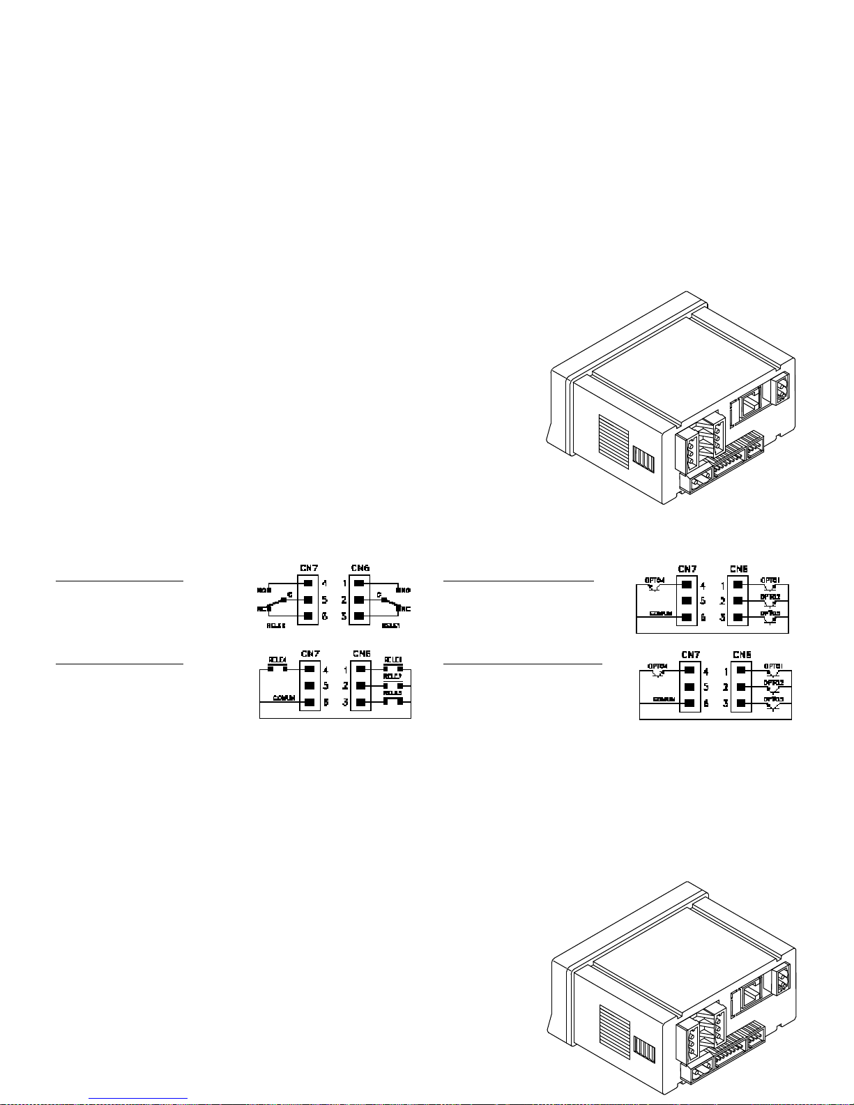
42
9.1.2 – Installation
Lift out the electronics assembly from the case and use a screw-driver to push on
the junctions between the case and the shadow areas to detach them from the
case. See fig. The so performed orifice will allow any of the setpoints (2RE, 4RE,
4OP or 4OPP) board output connectors be brought out at the rear of the
instrument. The option is installed by plugging the connector in the main board
location. Insert the card pin in the corresponding main board slot and push down
to attach both connectors.
If the instrument is to be installed in high vibrating environments, it is
recommended to solder the card to the main board making use of the copper
tracks on both sides of the card pin and around the main board hole on its solder
side.
9.1.3 – Wiring
2RE - 2 RELAYS OPTION
PIN 4 = NO2 PIN 1 = NO1
PIN 5 = COMM2 PIN 2 = COMM1
PIN 6 = NC2 PIN 3 = NC1
4RE - 4 RELAYS OPTION
PIN 4 = RL4 PIN 1 = RL1
PIN 5 = N/C PIN 2 = RL2
PIN 6 = COMM PIN 3 = RL3
4OP - OPTION 4 OPTOS NPN
PIN 4 = OP4 PIN 1 = OP1
PIN 5 = N/C PIN 2 = OP2
PIN 6 = COMM PIN 3 = OP3
4OPP – OPTION 4 OPTOS PNP
PIN 4 = OP4 PIN 1 = OP1
PIN 5 = N/C PIN 2 = OP2
PIN 6 = COMM PIN 3 = OP3
9.1.2 – Installation
Lift out the electronics assembly from the case and use a screw-driver to push on
the junctions between the case and the shadow areas to detach them from the
case. See fig. The so performed orifice will allow any of the setpoints (2RE, 4RE,
4OP or 4OPP) board output connectors be brought out at the rear of the
instrument. The option is installed by plugging the connector in the main board
location. Insert the card pin in the corresponding main board slot and push down
to attach both connectors.
If the instrument is to be installed in high vibrating environments, it is
recommended to solder the card to the main board making use of the copper
tracks on both sides of the card pin and around the main board hole on its solder
side.
Page 43

43
Each output card is supplied with an adhesive label that indicates the wiring connections of each option. To help
identifying each terminal, this label should be placed in the lower side of the meter case, beside the basic functions
label.
NOTE: In case that the outputs are used to drive inductive loads, it is recommended to add an RC network between
the coil terminals (preferably) or between the relay contacts to limit electromagnetic effects.
9.1.4 – technical specifications
CHARACTERISTICS 2RE OPTION 4RE OPTION
MAX.CURRENT(RESISTIVE LOAD) ...................................................... 8 A ......................................... 5 A
MAX.POWER ................................................................. 2000 VA / 192 W .................... 1250 VA / 150 W
MAX.VOLTAGE ........................................................... 250 VAC / 150 VDC ................. 277 VAC / 125 VDC
CONTACT RESISTANCE ............................................................ Max. 3mΩ ............................. Max. 30mΩ
SWITCHING TIME .................................................................. Max. 10ms .............................. Máx. 10ms
4OP and 4OPP OPTION
MAX VOLTAGE ............................................................................. 50 VDC
MAX CURRENT ............................................................................ 50 mA
LEAKAGE CURRENT ........................................................... 100 µA (max.)
SWITCHING TIME ................................................................ 1 ms (max.)
Each output card is supplied with an adhesive label that indicates the wiring connections of each option. To help
identifying each terminal, this label should be placed in the lower side of the meter case, beside the basic functions
label.
NOTE: In case that the outputs are used to drive inductive loads, it is recommended to add an RC network between
the coil terminals (preferably) or between the relay contacts to limit electromagnetic effects.
9.1.4 – technical specifications
CHARACTERISTICS 2RE OPTION 4RE OPTION
MAX.CURRENT(RESISTIVE LOAD) ....................................................... 8 A ........................................ 5 A
Page 44
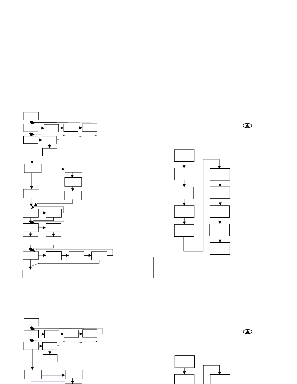
44
9.1. 5 - Setpoints menu diagram
in mode Fre
q
uencymeter / Tachometer
9.1.6 – Direct access to the setpoints value
programming
If any of the options corresponding to the setpoints has
been installed, it is possible to accede directly to the
setpoints value without need to go through the
programming menu just by pressing the
key in
PROG mode, as showed in diagram below, supposing that
the card installed are 4RE, 4OP or 4OPP, if it is the 2RE
card only Set1 y Set2 would appear.
-Pro-
888.88
SEt 1
SEt 2
888.88
SEt 3
888.88
SEt 4
888.88
StorE
Remember that the decimal point position
comes determined by what has been
programmed in the SCAL menu.
The complete programming of one of the setpoints is
showed here, it is valid for the rest of the setpoints.
±888.88
-Pro-
-Hi- -Lo-
888.88
88
-Hys-
-dLy-
no CH
A
LArM
Rojo
A
LArM
V
erde
A
LArM
A
marillo
SEtP
SEt 1
-on-
-off-
-Pro-
SEt 2
SEt 3
SEt 4
They can only be programmed if a 4RE,
4OP, 4OPP option has been installed or i
f
the logic function nº 13 has been
programmed
ProC
Total
H 8888
L 8888
*
* -Hys- cannot be
programmed for the totalizer
9.1. 5 - Setpoints menu diagram
in mode Fre
q
uencymeter / Tachometer
9.1.6 – Direct access to the setpoints value
programming
If any of the options corresponding to the setpoints has
been installed, it is possible to accede directly to the
setpoints value without need to go through the
programming menu just by pressing the
key in
PROG mode, as showed in diagram below, supposing that
the card installed are 4RE, 4OP or 4OPP, if it is the 2RE
card only Set1 y Set2 would appear.
-Pro-
SEt 1
SEt 3
The complete programming of one of the setpoints is
showed here, it is valid for the rest of the setpoints.
SEtP
SEt 1
-on-
-off-
-Pro-
SEt 2
SEt 3
SEt 4
T
hey can only be programmed if a 4RE,
4OP, 4OPP option has been installed or i
f
the logic function nº 13 has been
programmed
ProC
Total
Page 45
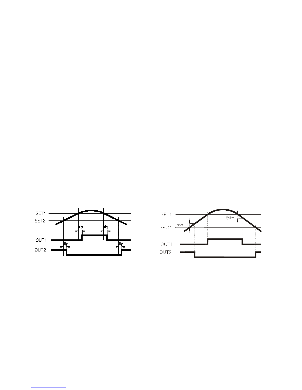
45
9.1.7 – Description of operation in Frequencymeter, Tachometer mode.
As programmed like independent setpoints, the alarm outputs activate when the display value reaches the userprogrammed value. The independent alarms programming requires definition of the following basic parameters:
b. HI/ LO ACTING MODE.
In HI mode, the output activates when the display value exceeds the setpoint level and in LO mode, the output
activates when the display value falls below the setpoint
c. PROGRAMMABLE TIME DELAY or HYSTERESIS.
Each output action can be deferred by a programmable time delay or hysteresis level.
The time delay is the time that takes the output to activate after passing through the setpoint in the up or down
direction, while the hysteresis band will be selected asymmetrical i.e. only acts on the output deactivation edge.
The delay is programmable in seconds, from 0 to 99.
The hysteresis can be programmed, in counts, within the full display range. The decimal point appears in the same
position as programmed in the display configuration module.
The figures 1 and 2 show the time delay action (dly) and the asymmetrical hysteresis action (hys-1) of two alarms
(SET1 and SET2) programmed to activate in HI mode (OUT1) and LO mode (OUT2)
Delay action
Asymmetrical hysteresis
9.1.7 – Description of operation in Frequencymeter, Tachometer mode.
As programmed like independent setpoints, the alarm outputs activate when the display value reaches the userprogrammed value. The independent alarms programming requires definition of the following basic parameters:
b. HI/ LO ACTING MODE.
In HI mode, the output activates when the display value exceeds the setpoint level and in LO mode, the output
activates when the display value falls below the setpoint
c. PROGRAMMABLE TIME DELAY or HYSTERESIS.
Each output action can be deferred by a programmable time delay or hysteresis level.
The time delay is the time that takes the output to activate after passing through the setpoint in the up or down
direction, while the hysteresis band will be selected asymmetrical i.e. only acts on the output deactivation edge.
The delay is programmable in seconds, from 0 to 99.
The hysteresis can be programmed, in counts, within the full display range. The decimal point appears in the same
position as programmed in the display configuration module.
Page 46
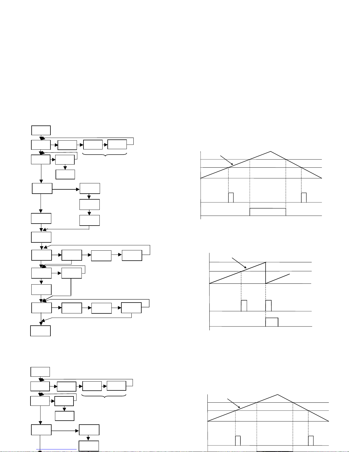
46
9.1. 8 – Diagram of the menu of Setpoints
T
hey can only be programmed if a 4RE,
4OP, 4OPP option has been installed o
r
if the logic function nº 13 has been
programmed
T
he complete programming of one of the setpoints is
showed here, it is valid for the rest of the setpoints.
SEtP
SEt 1
-on-
-off-
-Pro-
SEt 2
SEt 3
SEt 4
±888.88
A
LArM
Yellow
-4-
-Pro-
-1-
-2-
8.8
-InP- -LAtcH-
no CH
A
LArM
Red
A
LArM
Green
nodE
-3-
ProC
Total
H 8888
L 8888
9.1. 8 – Diagram of the menu of Setpoints
T
hey can only be programmed if a 4RE,
4OP, 4OPP option has been
installed or
if the logic function nº 13
has been
programmed
T
he complete programming of one of the setpoints is
showed here, it is valid for the rest of the setpoints.
SEtP
SEt 1
-on-
-off-
-Pro-
SEt 2
SEt 3
SEt 4
ProC
Total
H 8888
9.1.9 - Description of Mode “relays operating as Counter/
Chronometer
Mode 1 No function. When configured as Process or total counter,
enables the output (pulse or latch), whether it comes from a lower
or higher value than the programmed value.
Mode 2 Reset
The value of the variable to which the setpoint is related is reset to
zero (or to the offset value) when enabling output. In this mode the
output cannot be programmed as Latch.
9.1.9 - Description of Mode “relays operating as Counter/
Chronometer
Mode 1 No function. When configured as Process or total counter,
enables the output (pulse or latch), whether it comes from a lower
or higher value than the programmed value.
OUT 2
Latch
OUT 1
Pulse 1s
Set 2
Set 1
Counter
ProC or
T
otal
0 or offset
OUT 2
Pulse 2 s
Mode 2
OUT 1
Pulse 1s
Mode 1
Set 2
Set 1
Counter
ProC or
T
otal
0 or offse
t
OUT 1
Pulse 1s
Set 2
Set 1
Counter
ProC or
T
otal
0 or offset
Page 47
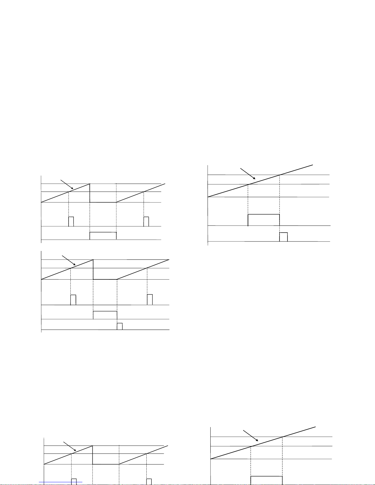
Mode 4 Clear
On enabling the output, the previous setpoint output is
disabled, if it had been enabled.
(The setpoint prior to 1 is 4)
47
Mode 3 Stop
All process, batch and total counters, where applicable, will
stop during the output enabling time. Where the output is
pulse, the counters will restart once the enabling time is
complete. If the output is latch, the counters will restart
when the counter to which the setpoint is related is reset.
Mode 3 Stop
All process, batch and total counters, where applicable, will
stop during the output enabling time. Where the output is
pulse, the counters will restart once the enabling time is
complete. If the output is latch, the counters will restart
when the counter to which the setpoint is related is reset.
Mode 4 Clear
On enabling the output, the previous setpoint output is
disabled, if it had been enabled.
(The setpoint prior to 1 is 4)
OUT 2
Pulse 4 s
M
ode
3
OUT 1
Pulse 1s
Mode 1
Set 2
Set 1
Counter
ProC or
T
otal
0 or offset
OUT 2
Latch
M
ode
3
OUT 1
Pulse 1s
Mode 1
Set 2
Set 1
Counter
ProC or
T
otal
0 or offset
Reset
OUT 1
Pulse1s
M
ode
4
OUT 4
Latch
Mode 1
Se
t
1
Set 4
Counter
ProC or
T
otal
0 or offse
t
Mode 3 Stop
All process, batch and total counters, where applicable, will
stop during the output enabling time. Where the output is
pulse, the counters will restart once the enabling time is
complete. If the output is latch, the counters will restart
when the counter to which the setpoint is related is reset.
OUT 1
Pulse 1s
Set 2
Set 1
Counter
ProC or
T
otal
0 or offset
OUT 4
Latch
Se
t
1
Set 4
Counter
ProC or
T
otal
0 or offse
t
Page 48

9.2 – RS2 / RS4 Output
9.2.1 – Introduction
The RS232C output option consists of an additional card (reference RS2) that is installed in the M2 plug-in connector of
the instrument’s main board. The card incorporates one 4 wires telephone socket with output at the rear of the
instrument.
The RS485 output option consists of an additional card (reference RS4 that is also installed in the M2 plug-in connector of
the instrument’s main board. The card incorporates a 6-pin / 4-contact telephone socked with output at the rear of the
instrument.
The serial output permits to construct a communication line through which a master device can request the transmission
of data such de display value, setpoint values, peak, valley, tare (or offset in case of thermometers) and to perform
operations such as tare of the display, reset of the peak, valley or tare memories and update setpoint values..
The output option is totally software configurable as for the transmission rate (1200, 2400, 4800, 9600 or 19200 Baud),
the instrument’s address (from 00 to 99), the protocol (ASCII, ISO 1745 and MODBUS RTU).
The operating mode is half-duplex and it normally stands in data reception mode until reception of a message.
A valid data transmission may cause the immediate execution of an action (tare, reset of peak, valley or tare memories
modification of setpoint values) or the transmission of a response from the instrument (display value, one of the setpoints
value, peak, valley, tare / offset). Only the display value can be called up via external contact according diagram in page 9
of RS2 manual.
Three communication modes are available; the ASCII mode uses a simple protocol compatible with several DITEL
instruments. The ISO mode, in accordance with the ISO 1745 norm, allows a more effective communication in noisy
environments as it checks the messages validity checking both transmission and reception. And eventually the protocol
MODBUS RTU
As you will see in the functions table, the protocol ASCII uses 1 or 2 bytes according to the command type and the
protocol ISO 1745 imposes the use of two bytes per command.
48
9.2 – RS2 / RS4 Ouput
9.2.1 – Introduction
The RS232C output option consists of an additional card (reference RS2) that is installed in the M2 plug-in connector of
the instrument’s main board. The card incorporates one 4 wires telephone socket with output at the rear of the
instrument.
The RS485 output option consists of an additional card (reference RS4 that is also installed in the M2 plug-in connector of
the instrument’s main board. The card incorporates a 6-pin / 4-contact telephone socked with output at the rear of the
instrument.
The serial output permits to construct a communication line through which a master device can request the transmission
of data such de display value, setpoint values, peak, valley, tare (or offset in case of thermometers) and to perform
operations such as tare of the display, reset of the peak, valley or tare memories and update setpoint values..
The output option is totally software configurable as for the transmission rate (1200, 2400, 4800, 9600 or 19200 Baud),
the instrument’s address (from 00 to 99), the protocol (ASCII, ISO 1745 and MODBUS RTU).
The operating mode is half-duplex and it normally stands in data reception mode until reception of a message.
Page 49
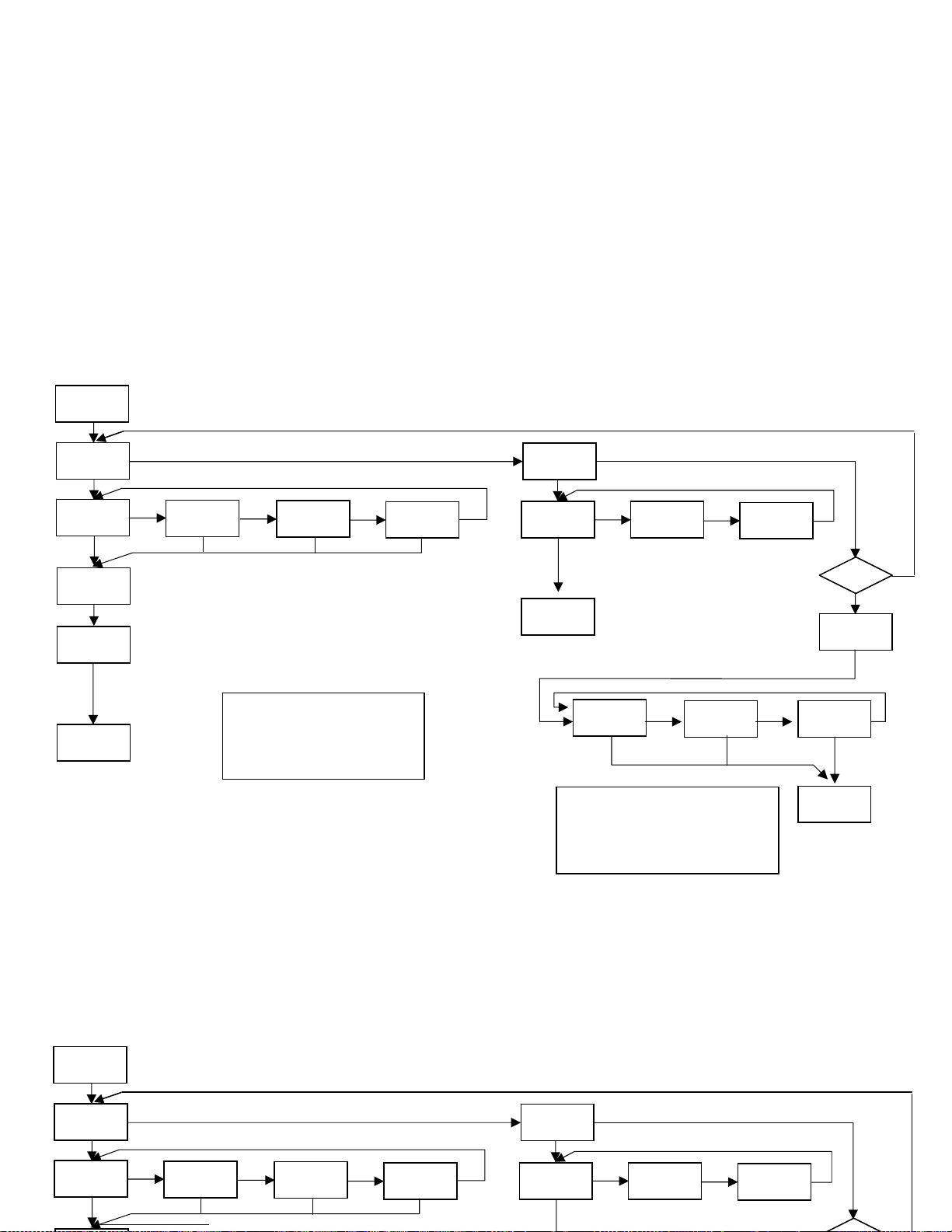
49
9.2. 2 – Diagram of the menu Input RS
Si
rSout
bAud
1200
4800
9600
19200
Adr
88
-Pro-
trAnS
Prt 1 Prt 2
Prt 3
-Pro-
dLy
3
-Pro-
RS4?
2
1
Prt1= ASCII
Prt2=ISO 1745
Prt3=MODBUS
1: dLY = 30 ms
2: dLY = 60 ms
3: dLY = 100 ms
9.2. 2 – Diagram of the menu Input RS
rSout
bAud
1200
4800
9600
19200
trAnS
Prt 1 Prt 2
Prt 3
Page 50

50
ASCII PROTOCOL
The Transmission format is: 1 START bit, 8 DATA bits, NO parity bit and 1 STOP bit.
• MESSAGE FORMAT TO BE SENT
A message sent to the instrument must be composed of the following sequence of ASCII characters:
* D d C C X ........................... X CR
One " * " byte [ASCII 42] of start of message.
Two address bytes (from 00 to 99).
One or two ASCII characters corresponding to the desired command according to the functions table (List of commands).
In case that the command request for a modification of parameters, the new value shall be transmitted with one byte of sign
(+ [ASCII 43] or - [ASCII 45] ) followed by a block of N ASCII characters (depending on model), including the decimal point.
One " CR " [ASCII 13] character of end of message. CR= Carriage Return
• MESSAGE FORMAT FROM INSTRUMENT
The data sent from the instrument as a response to a data request type command from the master device is the following:
SP X ........................... X CR
One byte of blank space [ASCII 32].
One text (requested values) consisting of a byte of sign (+ [ASCII 43] or - [ASCII 45] ) followed by a block of N ASCII
characters (depending on model) including the decimal point.
One " CR " byte [ASCII 13] of end of message. CR = Carriage Return
If the command belongs to “orders” or “changing parameters”, the instruments gives no response.
ASCII PROTOCOL
The Transmission format is: 1 START bit, 8 DATA bits, NO parity bit and 1 STOP bit.
• MESSAGE FORMAT TO BE SENT
A message sent to the instrument must be composed of the following sequence of ASCII characters:
* D d C C X ........................... X CR
One " * " byte [ASCII 42] of start of message.
Two address bytes (from 00 to 99).
Page 51

5051
ISO 1745 PROTOCOL
The transmission format is: 1 START bit, 7 DATA bits, 1 EVEN PARITY bit and 1 STOP bit.
• MESSAGE FORMAT TO BE SENT
The message format, as sent from the master device, must consist of the following sequence of characters:
SOH D d STX C C X ...... X ETX BCC
One byte SOH of start of message [ASCII 01].
Two bytes corresponding the first to the tens and the second to the units of the instrument address number.
One byte STX of start of text [ASCII 02].
Two commands bytes according to the functions table.
In case of commands that change parameters, a block of N bytes corresponding to the new value including sign and decimal point.
One byte ETX of end of text [ASCII 03].
One control byte BCC calculated in the following manner:
Perform an exclusive-OR with all bytes between the STX (not included) and the ETX (included).
- If the obtained byte (in ASCII format) is higher than 32, it can be taken as the BCC.
- If the obtained byte (in ASCII format) is lower than 32, the BCC byte will be obtained by adding 32.
• MESSAGE FORMAT FROM INSTRUMENT
The format of a message as sent from the instrument in response to a command from the master device is the following:
2. In case of commands that ask for transmission of a value (data request type):
SOH D d STX X .................. X ETX BCC
One byte SOH of start of message [ASCII 01].
Two address bytes.
One byte STX of start of text [ASCII 02].
N bytes corresponding to the requested value (including the sign and decimal point).
One byte ETX of end of text [ASCII 03].
One control byte BCC calculated with the method described in above.
2. In case of commands that do not imply the return of a value (command type or changing parameter):
D d ACK or D d NAK
The instrument sends a confirmation when it receives a message.
If the message has been correctly received and interpreted, the response will consist of two address bytes and one “ACK" [ASCII 06]
If the received message has not been well interpreted or it has been detected as to have errors, the response will be two address bytes and a "NAK"
[ASCII 21].
ISO 1745 PROTOCOL
The transmission format is: 1 START bit, 7 DATA bits, 1 EVEN PARITY bit and 1 STOP bit.
• MESSAGE FORMAT TO BE SENT
The message format, as sent from the master device, must consist of the following sequence of characters:
SOH D d STX C C X ...... X ETX BCC
One byte SOH of start of message [ASCII 01].
Two bytes corresponding the first to the tens and the second to the units of the instrument address number.
One byte STX of start of text [ASCII 02].
Two commands bytes according to the functions table.
In case of commands that change parameters, a block of N bytes corresponding to the new value including sign and decimal point.
One byte ETX of end of text [ASCII 03].
One control byte BCC calculated in the following manner:
Perform an exclusive-OR with all bytes between the STX (not included) and the ETX (included).
Page 52

52
List of commands
DATA REQUEST
A
SCII ISO Information
P 0P Peak value
V
0V Valley value
T 0T Tare or offset value
D 0D Display value
L1 L1 Setpoint 1 value
L2 L2 Setpoint 2 value
L3 L3 Setpoint 3 value
L4 L4 Setpoint 4 value
NB Cards installed
Returns:
- “04”: RS2
- “05”: RS2, 2RE
- “06”: RS2, 4OP
- “08”: RS4
- “09”: RS4, 2RE
- “0:”: RS4, 4 Setpoints(4RE, 4OP or 4OPP)
- “44”: NMA or NMV, RS2
- “45”: NMA or NMV, RS2, 2RE
- “46”: NMA or NMV, RS2, 4 Setpoints(4RE, 4OP or
4OPP)
- “48”: NMA or NMV, RS4
- “49”: NMA or NMV, RS4, 2RE
- “4:”: NMA or NMV, RS4, 4 Setpoints(4RE, 4OP or
4OPP)
TT Model + Version
MODIFICATION OF DATA
A
SCII ISO Parameter
M1 M1 Change the setpoint1 value in memory
M2 M2 Change the setpoint2 value in memory
M3 M3 Change the setpoint3 value in memory
M4 M4 Change the setpoint4 value in memory
COMMANDS
A
SCII ISO Command
p 0p Peak reset
v 0v
V
alley reset
r 0r Tare reset
List of commands
DATA REQUEST
A
SCII ISO Information
P 0P Peak value
V
0V Valley value
T 0T Tare or offset value
D 0D Display value
L1 L1 Setpoint 1 value
L2 L2 Setpoint 2 value
L3 L3 Setpoint 3 value
L4 L4 Setpoint 4 value
NB Cards installed
Returns:
- “04”: RS2
- “05”: RS2, 2RE
MODIFICATION OF DATA
A
SCII ISO Parameter
M1 M1 Change the setpoint1 value in memory
M2 M2 Change the setpoint2 value in memory
M3 M3 Change the setpoint3 value in memory
M4 M4 Change the setpoint4 value in memory
COMMANDS
A
SCII ISO Command
p 0p Peak reset
v 0v
V
alley reset
r 0r Tare reset
Page 53

53
9.3 ANALOG OUTPUT
9.3.1 – Introduction
Two ranges of analog output (0-10 V and 4-20 mA) can be incorporated to the MICRA D by means of an additional card,
either the NMV card for voltage output or the NMA card for current output, which is installed on the meter's main board via
plug-in connector M3, both cards, cannot be used simultaneously.
The outputs are opto-isolated with respect to the signal input and the power supply.
The optional board provides a two terminal connector [(+) and (-)] that drives out a signal variation from 0 to 10V or from
4mA to 20mA proportional to a user-defined display range.
This way, the meter is furnished with a signal that can be used to control variables and operates at each moment
proportionally to the magnitude of the effect under control.
These signals can also be used to transmit display information to a variety of terminal equipment such as graphic recorders,
controllers, remote displays or other devices that accept input data in analog form.
The instrument will detect the type of option that has been installed and will operate in accordance.
The display values producing the full scale output (OUT-HI and OUT-LO) are also introduced via front-panel buttons in the
same programming module. The analog output then follows the display variation between the HI and LO programmed
points.
The output signal can be set up for reverse action by programming the low display for the high output (OUT-HI) and the
high display for the low output (OUT-LO).
9.3.2 – Installation of NMA or NMV option
Lift out the electronics assembly from the case and use a screwdriver to pull on the junctions between the case and the
grey-marked area to detach it from the case. The so performed orifice will allow the analog output board connector be
brought out at the rear of the instrument. Install the circuit board so that the lower pin fits into the corresponding main
board insertion slot and push down to plug the M3 option connector in the main board M3 location. If the instrument is to be
installed in high vibrating environments, it is recommended to solder the card to the main board making use of the copper
tracks on both sides of the card
p
in and around the main board hole on its solder side.
9.3 ANALOG OUTPUT
9.3.1 – Introduction
Two ranges of analog output (0-10 V and 4-20 mA) can be incorporated to the MICRA D by means of an additional card,
either the NMV card for voltage output or the NMA card for current output, which is installed on the meter's main board via
plug-in connector M3, both cards, cannot be used simultaneously.
The outputs are opto-isolated with respect to the signal input and the power supply.
The optional board provides a two terminal connector [(+) and (-)] that drives out a signal variation from 0 to 10V or from
4mA to 20mA proportional to a user-defined display range.
This way, the meter is furnished with a signal that can be used to control variables and operates at each moment
proportionally to the magnitude of the effect under control.
These signals can also be used to transmit display information to a variety of terminal equipment such as graphic recorders,
controllers, remote displays or other devices that accept input data in analog form.
The instrument will detect the type of option that has been installed and will operate in accordance.
Page 54
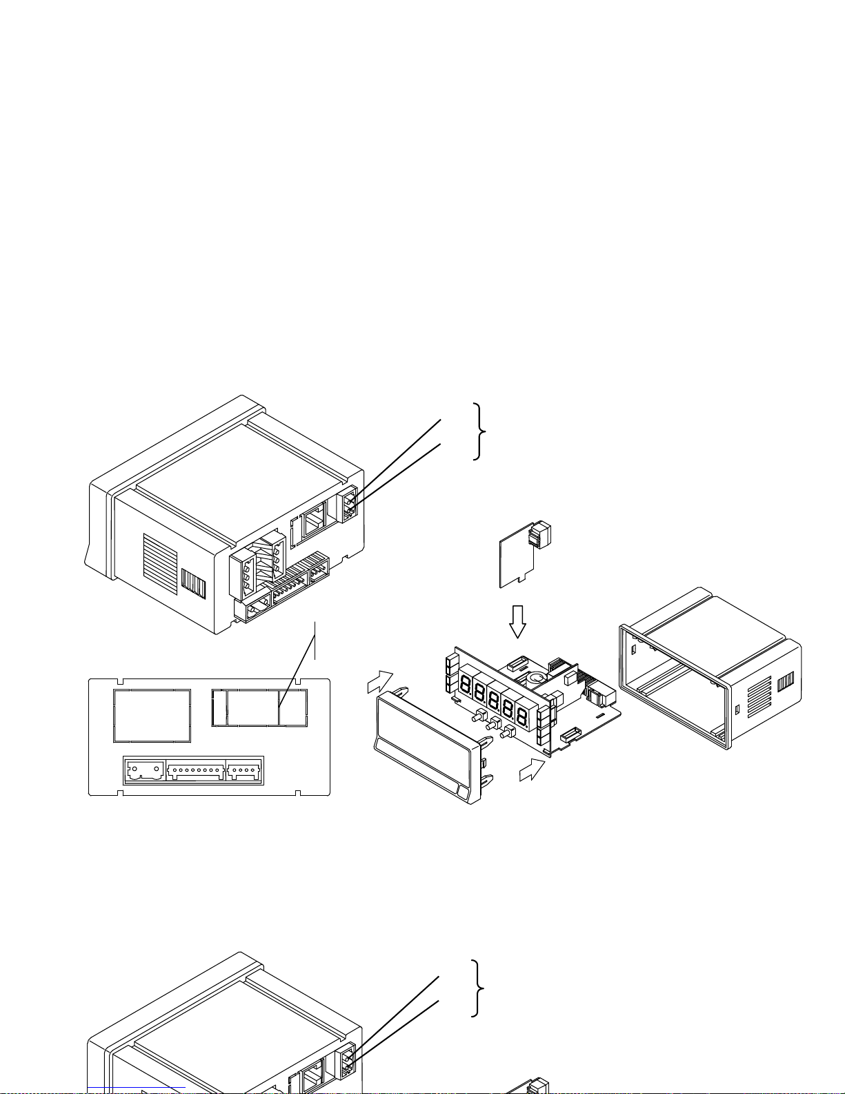
54
9.3.3 – Connection
Each output card is supplied with an adhesive label that indicates the wiring connections of each option (see fig.). To
help identifying each terminal, this label should be placed in the side of the meter case, beside the basic functions
label.
(-)
(+)
NMA (4-20 mA)
NMV (0-10 V)
NMA or NMV
Cutout
zones
9.3.3 – Connection
Each output card is supplied with an adhesive label that indicates the wiring connections of each option (see fig.). To
help identifying each terminal, this label should be placed in the side of the meter case, beside the basic functions
label.
(-)
(+)
NMA (4-20 mA)
NMV (0-10 V)
Page 55

55
9.3.4 – Technical specifications
CHARACTERISTICS NMA OUTPUT NMV OUTPUT
RESOLUTION ....................................................................... 13 BITS .................................................. 13 BITS
ACCURACY ............................................................. 0.1% F.S. ±1BIT ..................................... 0.1% F.S. ±1BIT
RESPONSE TIME ..................................................................... 50 ms ..................................................... 50 ms
THERMAL DRIFT ............................................................... 0.5 μA/ºC ............................................... 0.2 mV/ºC
MAXIMUM LOAD ............................................................... <= 500 Ω ................................................ >=10 KΩ
9.3.5 - Analog output menu diagram
4
Anout
outHI
±888.88
outLo
±888.88
-Pro-
Display value for 20 mA (NMA) / 10 V (NMV) output
Display value for 4 mA (NMA) / 0V (NMV) output
9.3.4 – Technical specifications
CHARACTERISTICS NMA OUTPUT NMV OUTPUT
RESOLUTION .......................................................................13 BITS ................................................... 13 BITS
ACCURACY ............................................................. 0.1% F.S. ±1BIT ...................................... 0.1% F.S. ±1BIT
RESPONSE TIME ..................................................................... 50 ms ...................................................... 50 ms
THERMAL DRIFT ............................................................... 0.5 μA/ºC ............................................... 0.2 mV/ºC
MAXIMUM LOAD ............................................................... <= 500 Ω ................................................. >=10 KΩ
9.3.5 - Analog output menu diagram
Page 56

56
10. Technical Characteristics
INPUT SIGNAL
Frequency meter and Tachometer
Frequency Limits
MIN frequency .............................................. 0.01Hz
MAX frequency without totalizer ..................... 19 KHz
MAX frequency with totalizer ........................ 9,9 KHz
Counter
MAX count rate (*)
Up or down without relays ............................. 20 KHz
Up or down with relays .................................. 15 KHz
Bidirectionnal Phase or Direc without relays .... 20 KHz
Bidirectionnal phase or Direc with relays ......... 15 KHz
Bidirectionnal Indep without relays................. 20 KHz
Bidirectionnal Indep with relays ..................... 15 KHz
EXCITATION ........................... 8V/24V DC @ 30mA
18Vdc (not stabilized) @ 100 mA
Contact closure
FILTER
Fc with duty cycle 50% .................................... 20Hz
Fc with duty cycle 30% .................................... 10Hz
INPUTS (2 CHANELS)
MAGNETIC PICKUP
Sensitivity ............... Vin (AC) > 60mVpp @ F < 1kHz
........................... >120 mVpp @ F >1 kHz
NAMUR
Rc .............................................. 3k3 (incorporated)
Ion ......................................................... < 1mA DC
Ioff ......................................................... > 3mA DC
TTL/24V DC (encoder)
Logic levels ................. "0" < 2.4V DC, "1" > 2.6V DC
NPN or PNP
Rc .............................................. 3K3 (incorporated)
Logic levels ................. "0" < 2.4V DC, "1" > 2.6V DC
CONTACT CLOSURE
Vc ...................................................................... 5V
Rc ................................................................... 3.9K
Fc (activated automatically) ............................. 20Hz
HIGH VOLTAGE INPUT (1 CHANNEL)
Voltage limits ..................................... 10 to 300V AC
INPUT SIGNAL
Frequency meter and Tachometer
Frequency Limits
MIN frequency .............................................. 0.01Hz
MAX frequency without totalizer .................... 40 KHz
MAX frequency with totalizer ......................... 10 KHz
Counter
MAX count rate (*)
INPUTS (2 CHANELS)
MAGNETIC PICKUP
Sensitivity .............. Vin (AC) > 60mVpp @ F < 1kHkz
........................... >120 mVpp @ F <1 kHz
NAMUR
Rc ............................................... 3k3 (incorporated)
Ion .......................................................... < 1mA DC
Ioff ......................................................... > 3mA DC
Page 57

57
COUNTER Y CHRONOMETER MEMORY
Non-volatile E2PROM retains all programming data and
count value when power is removed or interrupted.
DISPLAY
Type ................. 5 programmable tricolor 14 mm digits
LED's ........................... 8, control and status indication
Decimal Point ....................................... programmable
Sign ..................................... automatic s/configuration
Positive overflow indication ................................. OvEr
Negative overflow indication ............................... -OvEr
Counter display limits ............ Process -99999 to 99999
Totalizer …………………………… -99999999 to 99999999
Chronometer ranges .......... 4, from 999.99s to 9999.9h
Frequency ranges .... 0.01 Hz to 20KHz/10KHz(totalizer)
Tachometer range ... 0 to 99999(rpm), programmable
(rate)
Scale factor
Counter ............ programmable from 0.0001 to 99999
Freq/Tach ........ programmable from 0.0001 to 99999
Display update rate
Counter ........................................................... 100ms
Chronometer ................................................... 100ms
Frequency/Tachometer ........ programmable 0.1 to 9.9s
POWER
MICRA-D ................................. 85 to 265 Vac 50/ 60Hz
........................................... 100 to 300 V dc
MICRA-D6 ............................................... 10,5-70V DC
............................ 22 to 50 V ac 50/ 60 Hz
Consumption .............. 5W (without options), 10W max
ACCURACY
Frequency/Tachometer ................................... 0,005%
Chronometer………………………………………………….0, 01%
Temperature coefficient .............................. 50 ppm/°C
Warm up time ............................................. 5 minutes
AMBIENT
Indoor use
Operating temp. .................................... -10ºC to 60ºC
Storage temperature .......................... -25°C to +85°C
Relative humidity (non condensing) ...... < 95% at 40ºC
Max altitude .................................................... 2000m
MECHANICAL
Dimensions ........................ 96x48x60mm (DIN 43700)
Panel cutout ................................................ 92x45mm
Weight ............................................................... 200g
Case material ...................... Polycarbonate (UL 94 V-0)
Sealed front panel…………………………………………….IP65
COUNTER Y CHRONOMETER MEMORY
Non-volatile E2PROM retains all programming data and
count value when power is removed or interrupted.
DISPLAY
Type .................. 5 programmable tricolor 14 mm digits
LED's ........................... 8, control and status indication
Decimal Point ....................................... programmable
Sign ..................................... automatic s/configuration
Positive overflow indication ................................. OvEr
Negative overflow indication .............................. -OvEr
Counter display limits ............ Process -99999 to 99999
POWER
MICRA-D ................................ 85 to 265 Vac 50/ 60Hz
........................................... 100 to 300 V dc
MICRA-D6 .............................................. 10,5-70V DC
............................. 22 to 50 V ac 50/ 60 Hz
Consumption .............. 5W (without options), 10W max
ACCURACY
Frequency/Tachometer ...................................0,005%
Chronometer………………………………………………….0, 01%
Page 58
Manufacturer: DITEL - Diseños y Tecnología
S.A.
Adress: Poligono Industrial Les Guixeres
C/ Xarol 8 C
08915 BADALONA
SPAIN
Declares, that the product:
Description: Digital panel meter
multifunction
Model: MICRA-D
Conforms with the directives: EMC 89/336/CEE
LVD 73/23/CEE
EMC
EN 61000-6-2 Generic immunity
EN 61000-4-2 Electrostatic discharge Criteria B
Air discharge 8kV
Contact discharge 4kV
EN 61000-4-3 Electromagnetic fields RF Criteria A
10V/m
EN 61000-4-4 Fast transients Criteria B
Power supply Lines 2 kV
Signal Lines 1 kV
EN 61000-4-5 Surge Criteria B
1 kV L/N
2 kV L,N/Ground
1 kV Signal Lines and ground
EN 61000-4-6 RF conducted interferences Criteria A
10 V rms
EN 61000-4-11 Voltage dips and interruptions
30% reduction 0,5 period Criteria B
EN 61000-6-3 Generic emission
EN 55022/ CISPR22 Criteria A
EN 61010-1 General safety
Installation category II
Pollution degree 2
Conductive pollution excluded
Insulation type
Enclosure: Double
Inputs/Outputs: Basic
Date: 08.06.2007
Signed: José M. Edo
Function: Technical manager
DECLARATION OF CONFORMITY
Manufacturer: DITEL - Diseños y Tecnología
S.A.
Adress: Poligono Industrial Les Guixeres
C/ Xarol 8 C
08915 BADALONA
SPAIN
Declares, that the product:
EMC
EN 61000-6-2 Generic immunity
EN 61000-4-2 Electrostatic discharge Criteria B
Air discharge 8kV
Contact discharge 4kV
EN 61000-4-3 Electromagnetic fields RF Criteria A
10V/m
EN 61000-4-4 Fast transients Criteria B
Power supply Lines 2 kV
Signal Lines 1 kV
DECLARATION OF CONFORMITY
58
Page 59

The instruments are warranted against defective materials and workmanship for a period of
three years from date of delivery.
If a product appears to have a defect or fails during the normal use within the warranty
period, please contact the distributor from which you purchased the product.
This warranty does not apply to defects resulting from action of the buyer such as
mishandling or improper interfacing.
The liability under this warranty shall extend only to the repair of the instrument. No
responsibility is assumed by the manufacturer for any damage which may result from its
use.
All the DITEL products benefit from an unlimited and unconditional warranty of THREE (3)
years from the date of their purchase. Now you can extend this period of warranty up to
FIVE (5) years from the product commissioning, only by fulfilling the corresponding form.
Fill up the form in our website at:
http://www.ditel.es/warranty
The instruments are warranted against defective materials and workmanship for a period of
three years from date of delivery.
If a product appears to have a defect or fails during the normal use within the warranty
period, please contact the distributor from which you purchased the product.
This warranty does not apply to defects resulting from action of the buyer such as
mishandling or improper interfacing.
The liability under this warranty shall extend only to the repair of the instrument. No
Page 60

DISEÑOS Y TECNOLOGIA, S.A.
Polígono Industrial Les Guixeres
C/ Xarol 8 C
08915 BADALONA-SPAIN
Tel: +34 - 93 339 47 58
Fax: +34 - 93 490 31 45
E-mail: [email protected]
www.ditel.es
INSTRUCTIONS FOR THE RECYCLING
This electronic instrument is covered by the 2002/96/CE European Directive so, it is properly marked with
the crossed-out wheeled bin symbol that makes reference to the selective collection for electrical and
electronic equipment which indicates that at the end of its lifetime, the final user cannot dispose of it as
unsorted municipal waste.
In order to protect the environment and in agreement with the European legislation regarding waste of
electrical and electronic equipments from products put on the market after 13 August 2005, the user can
give it back, without any cost, to the place where it was acquired to proceed to its controlled treatment and
recycling.
INSTRUCTIONS FOR THE RECYCLING
This electronic instrument is covered by the 2002/96/CE European Directive so, it is properly marked with
the crossed-out wheeled bin symbol that makes reference to the selective collection for electrical and
electronic equipment which indicates that at the end of its lifetime, the final user cannot dispose of it as
unsorted municipal waste.
In order to protect the environment and in agreement with the European legislation regarding waste of
electrical and electronic equipments from products put on the market after 13 August 2005, the user can
 Loading...