

Page 1
C
ODE: 307
2
7126
EDITION: 0
5
-0
9
-20
0
6
TACHOMETER - TOTALIZER
PART 1 / 2
MODEL BETA-D
PROTOCOL MODBUS-RTU COMPATIBLE
C
ODE: 307
2
7126
EDITION: 0
5
-0
9
-20
0
6
INSTRUCTIONS MANUAL
COUNTER
TOTALIZER
TACHOMETER - TOTALIZER
PART 1 / 2
MODEL BETA-D
PROTOCOL MODBUS-RTU COMPATIBLE
Page 2

2
2
This catalogue does not constitute a formal
agreement. All information given in this manual i
s
subject to change without notice.
The KOSMOS SERIES brings a new philosophy in digital panel
instrumentation which is ex
p
ressed by multipurpose,
modular
-concept devices providing a rich array of basic
functions and advanced capabilities.
With a fully MODULAR DESIGN, it is
p
ossible to implement a
wide variet
y
of applications by only adding the adequate
options.
Intelli
g
ence within allows the meter to recognize the options
installed and ask for the necessar
y p
arameters to properly
function within desire
d margins. The basic instrument without
output options omits these data in the program routines.
The instrument's CALIBRATION is made at the factor
y
eliminating the need for adjustment potentiometers.
An
y
circuit or option that may need any adjust incorporates a
memor
y
where calibration parameters are stored, making it
p
ossible the optional cards be totally interchangeable without
need of any subsequent adjust.
Custom CONFIGURATION for specific applications can be
made
q
uickly and easily through five front panel keys,
followin
g
structured choice menus aided by display prompts
at eac
h programming step.
Other features of the KOSMOS family include :
CONNECTIONS via plug-in terminal blocks without
screws and CLEMP-WAGO clips cable retention system.
DIMENSIONS
Models ALPHA & BETA 96x48x120 mm DIN 43700
Models MICRA & JR/JR20 96x48x6
0 mm DIN 43700
CASE MATERIAL UL-94 V0-rated polycarbonate.
PANEL INSTALLATION by means of single part
fingertip without screws.
To guarantee the meter's technical specifications, it is advised to check
its calibration at periodical intervals according to the ISO9001
standards for the particular application operating criteria. Calibration
should be performed at the factory or in a qualified laboratory.
INTRODUCTION TO THE
KOSMOS SERIES
This catalogue does not constitute a formal
agreement. All information given in this manual is
subject to change without notice.
The KOSMOS SERIES brings a new philosophy in digital panel
instrumentation which is ex
p
ressed by multipurpose,
modular
-concept devices providing a rich array of basic
functions and advanced capabilities.
With a full
y
MODULAR DESIGN, it is possible to implement a
wide variet
y
of applications by only adding the adequate
options.
Intelli
g
ence within allows the meter to recognize the options
installed and ask for the necessar
y p
arameters to properly
function within des
ired margins. The basic instrument without
output options omits these data in the program routines.
The instrument's CALIBRATION is made at the factor
y
eliminating the need for adjustment potentiometers.
Any circuit or option that may need any adjust incor
p
orates a
memor
y
where calibration parameters are stored, making it
p
ossible the optional cards be totally interchangeable without
need of any subsequent adjust.
Custom CONFIGURATION for specific applications can be
made
q
uickly and easily through five front panel keys,
following structured choice menus aided b
y
display prompts
at each programming step.
Other features of the KOSMOS family include :
CONNECTIONS via plug-in terminal blocks without
screws and CLEMP-WAGO clips cable retention system.
DIMENSIONS
Models ALPHA & BETA 96x48x120 mm DIN 43700
M
odels MICRA & JR/JR20 96x48x60 mm DIN 43700
CASE MATERIAL UL-94 V0-rated polycarbonate.
PANEL INSTALLATION by means of single part
fingertip without screws.
To guarantee the meter's technical specifications, it is advised to
check
its calibration at periodical intervals according to the ISO9001
standards for the particular application operating criteria. Calibration
should be performed at the factory or in a qualified laboratory.
Page 3
3
3
1.2.General information
1.1. Introduction
1.2. Panel functions description
Setting up
2.1. Package contents
2.2. Supply. Connectors
2.3. I
nput configuration. Connections
2.4. Programming introduction
2.5. Programming guide and summary of functions
4-5
6-7
8
9-10
11-12
13-14
15-16
3.
Counter configuration
Index
17
4.
Tachometer configuration
Index
27
5.
Batch counter
Index
35
6.
Keyboard and back connector functions. Lock-out
Index
40
7.
Characteristics, dimensions and mounting
Index
49
APPENDIX
Index
59
INDEX
1.2.General information
1.1. Introduction
1.2. Panel functions description
Setting up
2.1. Package contents
2.2. Supply. Connectors
2.3. Input configuration. Connections
2.4. Programming introduction
2.5. Programming guide and summary of functions
4-5
6-7
8
9-
10
11-12
13-14
15-16
3.
Counter configuration
Index
17
4.
Tachometer configuration
Index
27
5.
Batch counter
Index
35
6.
Keyboard and back connector functions. Lock-out
Index
40
7.
Characteristics, dimension
s and mounting
Index
49
APPENDIX
Index
59
Page 4
4
4
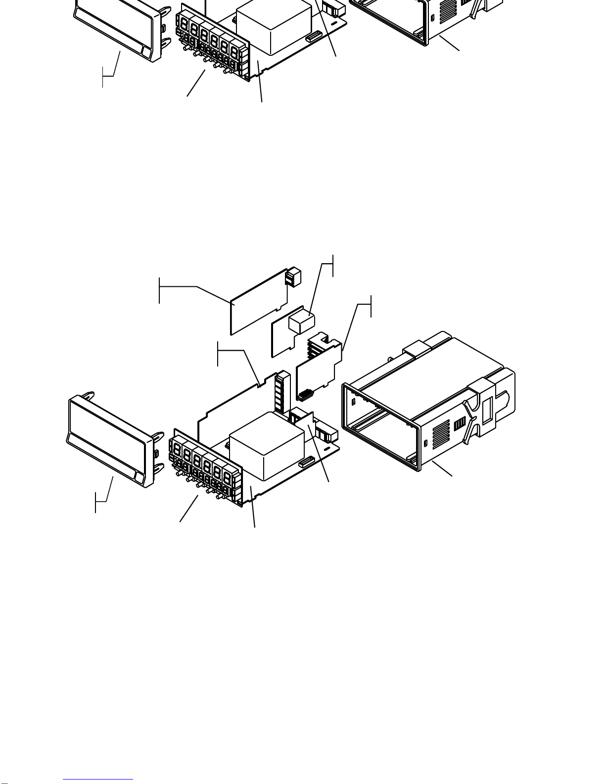
FRONT
COVER
ANALOG OUTPUT
OPTION
INPUT CARD
RS232C/ RS485
OUTPUT OPTION
RELAY/ OPT
O
OUTPUT OPTION
POWER CIRCUIT
FILTER
CASE WITH
FIXING CLIPS
MAIN BOARD
DISPLAY
FRONT
COVER
ANALOG OUTPUT
OPTION
INPUT CARD
RS232C/ RS485
OUTPUT OPTION
RELAY/ OPTO
OUTPUT OPTION
POWER CIRCUIT
F
ILTER
CASE WITH
FIXING CLIPS
MAIN BOARD
DISPLAY
Page 5

5
5
The Beta-D meter accepts digital inputs from a variety of
sources including switch contact, outputs from TTL circuits,
magnetic pickups ,NAMUR, PNP, NPN or encoder (TTL/24V).
The basic configuration is like one channel counter, where
one in
p
ut is used like main input counter and the other can
be used like active input, direction or counting inhibit, other
configuration is like a three channel counter, where two
phy
sical input count separately generating two independent
counters and with the
p
ossibility to make arithmetical
operations between them and generate a third counter.
In both cases, every counter carr
y
a totalizer shown thanks
to the second display of the BETA-D.
Alwa
y
s is possible to change the main counter to a
tachometer, b
y
an easy menu selection. The tachometer
has also a totalizer allowin
g
to show at the same time the
flow and Total volume ac
cumulated.
If the totalizer associated to the tachometer is bi
-
directional,
this has in addition indication of rotating direction
General characteristics :
Count signals in
quadrature x1, x2 y x4
.
Multiplier factor
pr
ogrammable from 0.0001 to 9999
Anti-debounce filter
100Hz, selectable
Counting selection by fall and rise edge or only by
rise
edge.
Batch counter with automatic cycle
(increases of one
unit of batch counter and automatic reset ever
y
time that
the main variable overcomes the programmed level)
or
manual
(increases one unit the batch counter every time
that is done a reset of partial counter).
Offset
programmable or stored from display
Function re-
load
(manual introduction of starting count of
the variables)
I nhibition of keyboard functions
offset, reset, load and
visual
Refresh of display
every 10ms
Store of process , batch and total
values on Power-off
4 logical inputs with programmable functions of :
Printing setpoints and its situation
Selective printing
of variables
Selective reset of variables,
p
ulse, with hold or with stop of
counter
Hold of display, of setpoints and outputs
Inhibition of inputs
1.1. Introduction to BETA
The Beta-D meter accepts digital inputs from a variety of
sources includin
g
switch contact, outputs from TTL circuits,
magnetic pi
ckups ,NAMUR, PNP, NPN or encoder (TTL/24V).
The basic configuration is like one channel counter, where
one in
p
ut is used like main input counter and the other can
be used like active in
p
ut, direction or counting inhibit, other
configuration is like a three channel counter, where two
phy
sical input count separately generating two independent
counters and with the
p
ossibility to make arithmetical
operations between them and generate a third counter.
In both cases, every counter carry a totalizer shown thank
s
to the second display of the BETA-D.
Alwa
y
s is possible to change the main counter to a
tachometer, b
y
an easy menu selection. The tachometer
has also a totalizer allowin
g
to show at the same time the
flow and Total volume accumulated.
If the totalizer
associated to the tachometer is bi
-
directional,
this has in addition indication of rotating direction
General characteristics :
Count signals in
quadrature x1, x2 y x4
.
Multiplier factor
programmable from 0.0001 to 9999
Anti-debounce filter
100Hz, selectable
Counting selection by fall and rise edge or only by
rise
edge.
Batch counter with automatic cycle
(increases of one
unit of batch counter and automatic reset ever
y
time that
the main variable overcomes the programmed level)
or
manual
(increases one unit the batch counter every time
that is done a reset of partial counter).
Offset
programmable or stored from display
Function re-
load
(manual introduction of starting count of
the variables)
I nhibition of keyboard func
tions
offset, reset, load and
visual
Refresh of display
every 10ms
Store of process , batch and total
values on Power-off
4 logical inputs with programmable functions of :
Printing setpoints and its situation
Selective printing of variables
Selective reset of variables,
p
ulse, with hold or with stop of
counter
Hold of display, of setpoints and outputs
Inhibition of inputs
1.1. Introduction to BETA
-
D model
1.
GENERAL INFORMATION
Page 6
6
9
6
M
A
X
M
I
N
HOL
D
TARE
1
2
3
4
OFFSET
RESET
VISUAL
DATA
ESC
ENTER
LIMIT
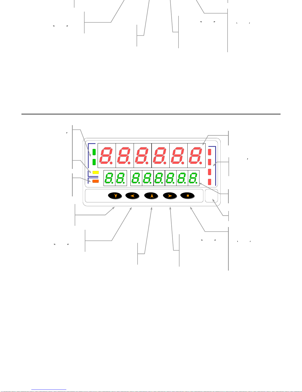
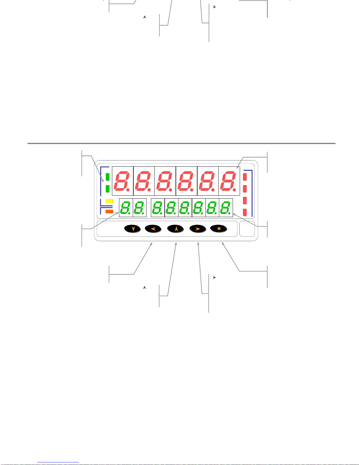
OFFSET key
As a counter, store the
actual value of display as
a offset value
RESET key
Allows to reset to zero or
a preset value the shown variable in
VISUAL routine.
LIMIT key
Shows at every push the
setpoint values
SECONDARY DISPLAY
Shows the variable TOTAL
se
lected
MAIN DISPLAY
Shows the main variable selected
Setpoint s LED
Point out according the number,
that the corresponding output is
active
LABEL
Engineering units
VI
SUAL key
Get routine VISUAL ,
showing at every push a
indication of the variable
on display at this moment
and its value
DATA key
Get access to the programming
mode
On
VISUAL routine allows to
pass to the visualization of
TOTAL variables on secondary
display . If is hold 3s allows to
program by key the actual
counting value
polarity LED s
As a counter, show polarity of
counting value
As
a tachometer, show the rotating
direction
LED HOLD
Shows that display is hold
LED OFFS
As a counter, shows that main
variable on display has a offset
in memory
Panel Functions d
escription
(Run mode)
M
A
X
M
I
N
HOL
D
TARE
1
2
3
4
OFFSET
RESET
VISUAL
DATA
ESC
ENTER
LIMIT
OFFSET key
As a counter, store the
actual value of display as
a offset value
RESET key
Allows to reset to zero or
a preset value the shown variable in
VISUAL routine.
LIMIT key
Shows at
every push the
setpoint values
SECONDARY DISPLAY
Shows
the variable TOTAL
selected
MAIN DISPLAY
Shows the main variable selected
Setpoint s LED
Point out according the number,
that the corresponding output is
active
LABEL
Engineering units
VISUAL key
Get routine VISUAL ,
showing at every push
a
indication of the variable
on display at this moment
and its value
DATA key
Get access to the programming
mode
On
VISUAL routine allows to
pass to the visualization of
TOTAL variables on secondary
display . If is hold 3s allows to
program by key the actual
counting value
polarity LED s
As a counter, show polarity of
counting value
As a tachometer, show the rotating
direction
LED HOLD
Shows that display is hold
LED OFFS
As a counter, shows that main
variable on display has a offset
in memory
1.2.
Panel Functions descrip
tion
(Run mode)
Page 7
7
7
M
A
X
M
I
N
HOL
D
TARE
1
2
3
4
OFFSET
RESET
VISUAL
DATA
ESC
ENTER
LIMIT
ESC key
Exit programming mode without
storing changes
key
Increase the selected
digit value in value
programming
SECONDARY DISPLAY
Shows the actual programming
parameter
programmed or the se
lected
parameter
key
In programming mode
shifts right one position
the blinking digit or shows
the possible options on
parameters selection
DATA key
A
ccept the changes done and
advance one step the
programming.
polarity LED
polarity of counting value
AUXILIARY DIGITS
Shows the menu number where
the programming is
Panel Functions description
(Prog mode)
M
A
X
M
I
N
HOL
D
TARE
1
2
3
4
OFFSET
RESET
VISUAL
DATA
ESC
ENTER
LIMIT
ESC key
Exit programming mode without
storing changes
key
Increase the selected
digit value in value
programming
SECONDARY DISPLAY
Shows
the actual programming
parameter
MAIN DISPLAY
Shows the variable value to be
programmed or the selected
parameter
key
In programming mode
shifts right one position
the blinking digit or shows
the possible options on
parameters selection
DATA key
Accept the changes done and
advance one ste
p the
programming.
polarity LED
In counter mode, shows the
polarity of counting value
AUXILIARY DIGITS
Shows the menu number where
the programming is
Page 8
y
p
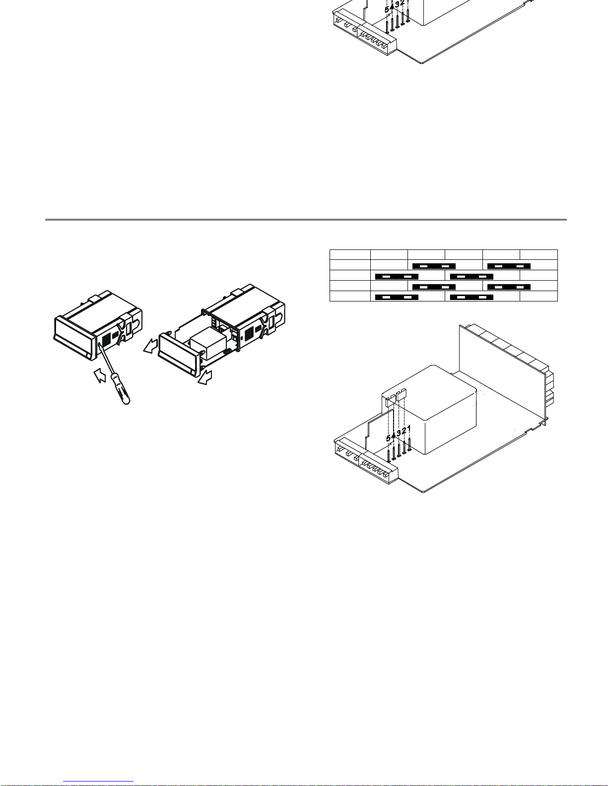
the electronics from the case as shown in figure 9.1.
fig. 9.1 : Disassembly
115/230 V AC: The instruments with 115/230 V AC
p
ower,
are shi
pp
ed from the factory for 230 V AC (USA market 115
V AC), see fi
g
ure 9.2. To change supply voltage to 115 V
AC, set jumpers as indicated (see table 9.1). The wirin
g
label should be modified to match new setups.
24/48 V AC: The instruments with 24/48 V AC
p
ower
su
pply
, are shipped from the factory for 24 V AC, see figure
9.2 To chan
g
e supply voltage to 48 V AC, set jumpers as
indicat
ed (see table 1). The wiring label should be modified
to match new setups.
Pin
1 2 3 4 5
230V AC
-
115V AC
-
48V AC
-
24V AC
-
fig. 9.2 : Jumpers situation
Tabla 9.1: Jumpers situation
.
Pin
1 2 3 4 5
230V AC
-
115V AC
-
48V AC
-
24V AC
-
fig. 9.2 : Jumpers situation
8
8
Power supply
2.2.
Power supply
Page 9
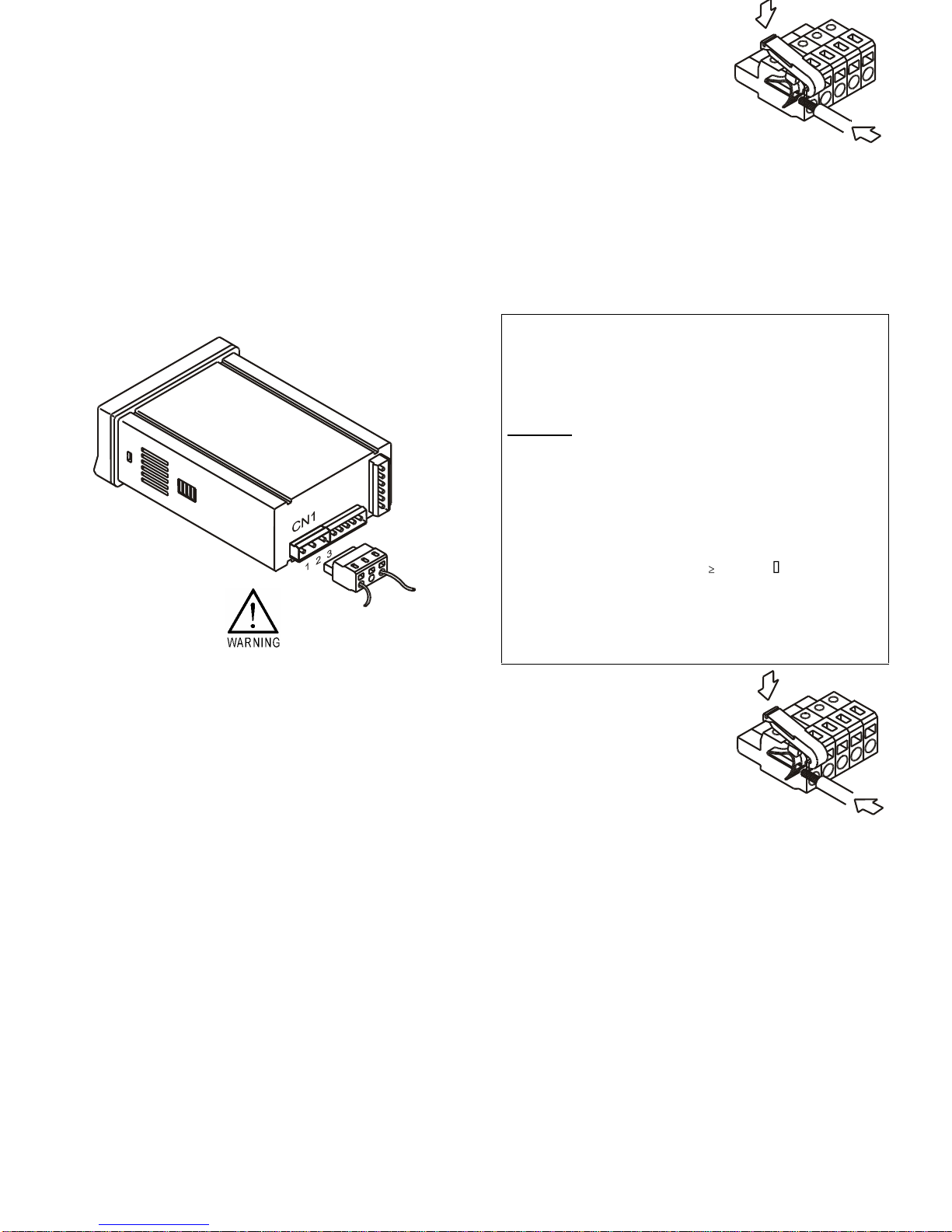
PIN 1 - AC PHASE
PIN 2 - GND (GROUND)
PIN 3 - AC NEUTRAL
easy reachable to the operator and clearly marked as the
disconnect device.
WARNING
In order to guarantee electromagnetic compatibility, the
following guidelines for cable wiring must be followed:
- Power supply wires must be routed separated from
signal wires.
Never
run power and signal wires in the
same conduit.
- Use shielded cable for signal wiring and connect the
shield to ground of the indicator (pin2 CN1).
-
The cable section must be
0.25 mm
I f not installed and used according to these
instructions, protection against hazards may be
impai
red.
POWER CONNECTION - CN1
PIN 1 - AC PHASE
PIN 2 - GND (GROUND)
PIN 3 - AC NEUTRAL
INSTALLATION
To meet the requirements of the directive EN61010-
1,
where the unit is permanently connected to the mains
supply it is obligatory to install a circuit breaking device
easy reachable to the operator and clearly marked as the
disconnect device.
WARNING
In order to guarantee electromagnetic compatibility, the
following guidelines for cable wiring must be followed:
- Power supply wires must be routed separated from
signal wires.
Never run power and signal wires in the
same conduit.
- Use shielded cable for signal wiring and connect the
shield to ground of the indicator (pin2 CN1).
-
The cable section must be
0.25 mm
I f not installed and used according to these
instructions, protection against hazards may be
impaired.
9
9
CONNECTORS
To perform wiring connections, remove the terminal block from the meter's connector, strip the wire
leaving fr
om 7 to 10 mm exposed and insert it into the proper terminal while pushing the fingertip down
to open the clip inside the connector as indicated in the figure.
Proceed in the same manner with all pins and plug the terminal block into the corresponding mete
r's
connector.
Each terminal accept cables of section between 0.08 mm² and 2.5 mm² (AWG 26 ÷ 14).
The blocks provide removable adaptors into each terminal to allow proper fastening for cable sections of
<0.5 mm².
CONNECTORS
T
o perform wiring connections, remove the terminal block from the meter's connector, strip the wire
leaving from 7 to 10 mm exposed and insert it into the proper terminal while pushing the fingertip down
to open the clip inside the connector as indicated in
the figure.
Proceed in the same manner with all pins and plug the terminal block into the corresponding meter's
connector.
Each terminal accept cables of section between 0.08 mm² and 2.5 mm² (AWG 26 ÷ 14).
The blocks provide removable adaptors into each t
erminal to allow proper fastening for cable sections of
<0.5 mm².
Page 10
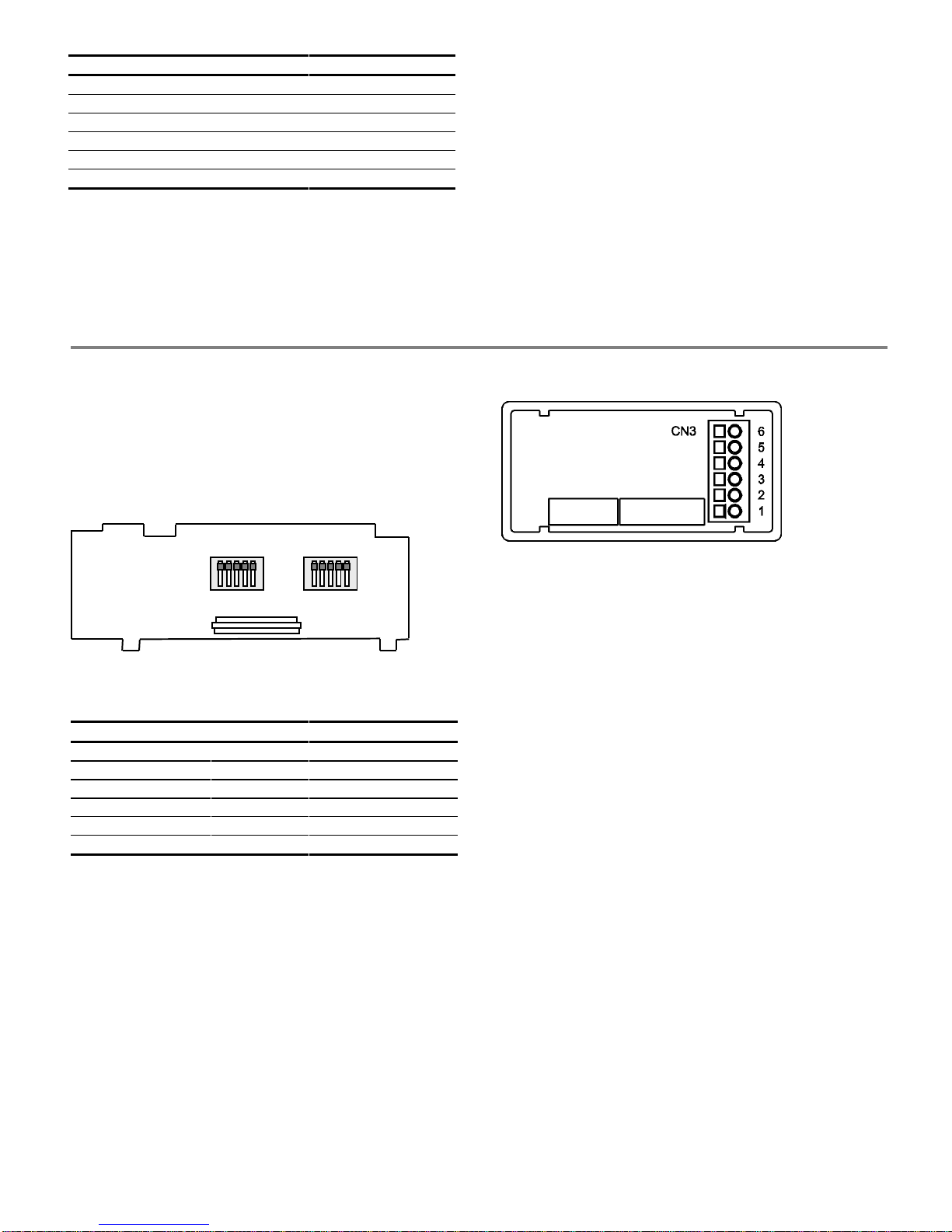
PIN 6 +EXC. 24V
(excitation output)
PIN 5 +EXC. 8V
(excitation output)
PIN 4
-IN (common inputs A and B)
PIN 3 +IN B
(positive input B)
PIN 2 +IN A
(positive input A)
PIN 1 N/C
(not connected)
When usin
g
two sensor the main sensor have to be
connected to the in
p
ut A and the secondary (which fixes
counting direction ) to the input B.
If onl
y
is used one sensor have to be connected to input A
leaving out the input B connection .
(see inputs wiring on page 12)
plug-in any sensor to the instrument.
On solder side of input circuit board there are two DIP-
switch for input configuration A (SW1) and input B (SW2).
The upper position is "ON".
Each input could be configured in a independent way.
The main sensor always have to be plugged-in on
input A.
1 2 3 4 5
1 2 3 4 5
Input B
SW2
Input
A
SW
1
on
on
fig.11.1
: Solder side of input circuit board
Table 11.1
. switch1 and switch2 Position
Sensorr
sw.1 sw.2 sw.3 sw.4 sw.5
Magnetic pickup
- - - -
ON
NAMUR sensor
-
ON
-
ON ON
TTL/24V (encoder)
-
ON ON
- -
NPN sensor
ON ON
- - -
PNP sensor
-
ON
-
ON
-
Switch contact
ON ON ON
-
ON
WIRING CN3
PIN 6 +EXC. 24V
(excitation output)
PIN 5 +EXC. 8V
(excitation output)
PIN 4
-IN (common inputs A and
B)
PIN 3 +IN B
(positive input B)
PIN 2 +IN A
(positive input A)
PIN 1 N/C
(not connected)
When usin
g
two sensor the main sensor have to be
connected to the in
p
ut A and the secondary (which fixes
counting direction ) to the input B.
If only is used one
sensor have to be connected to input A
leaving out the input B connection .
(see inputs wiring on page 12)
The input configuration should be done before to
plug-in any sensor to the instrument.
On solder side of input circuit board there are two DIPswitch for input configuration A (SW1) and input B (SW2).
The upper position is "ON".
Each input could be configured in a independent way.
The main sensor always have to be plugged-in on
input A.
1 2 3 4 5
1 2 3 4 5
Input B
SW2
Input
A
SW
1
on
on
fig.11.1
: Solder side of input circuit board
Table 11.1
. switch1 and switch2 Position
Sensorr
sw.1 sw.2 sw.3 sw.4 sw.5
Magnetic pickup
- - - -
ON
NAMUR sensor
-
ON
-
ON ON
TTL/24V (encoder)
-
ON ON
- -
NPN sensor
ON ON
- - -
PNP sensor
-
ON
-
ON
-
Switch c
ontact
ON ON ON
-
ON
10
10
2.3. Input configuration and wiring
2.3. Input configuration and wiring
Page 11
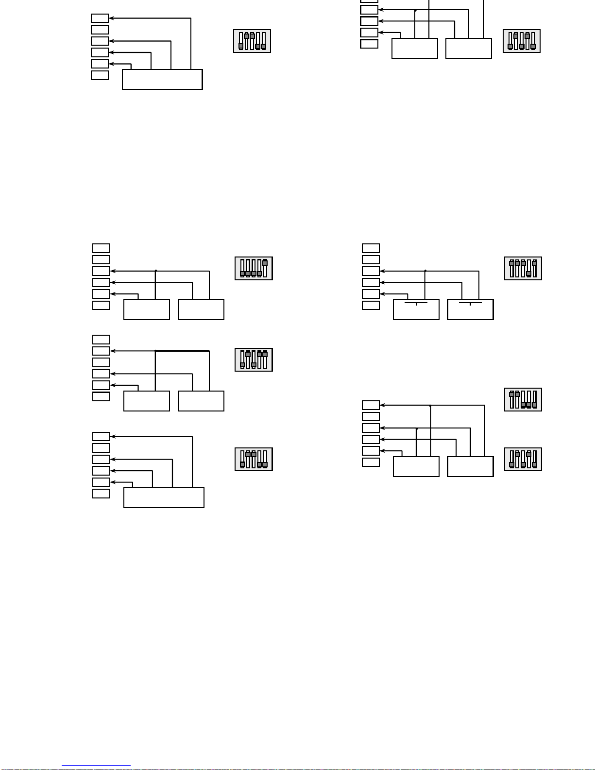
On Switch cont
act connection is recommended to program
the filter anti-debounce Fc=100Hz (see page 24).
11
11
6
5
4
3
2
1
Main
Secondary
+EXC (8V)
+IN B
+IN A
NAMUR
SW1 y SW2
ON
1 2 3 4 5
6
5
4
3
2
1
Main
Secondary
-
IN (comm)
+IN B
+IN A
MAGNETIC PICKUP
SW1 y SW2
ON
1 2 3 4 5
6
5
4
3
2
1
Encoder
+EXC (24V)
+IN B
+IN A
ENCODER
SW1 y SW2
ON
1 2 3 4 5
OUT1 OUT2 COMM EXC
-
IN (comm)
6
5
4
3
2
1
Main
Secondary
+EXC (24V)
+IN
B
+IN A
NPN
SW1 y SW2
ON
1 2 3 4 5
OUT COMM EXC
OUT COMM EXC
PNP
SW1 y SW2
ON
1 2 3 4 5
-
IN (comm)
6
5
4
3
2
1
Main
Secondary
-
IN (comm)
+IN B
+IN A
SWITCH CONTACT
SW1 y SW2
ON
1 2 3 4 5
6
5
4
3
2
1
MainSecondary
+EXC (8V)
+IN B
+IN A
NAMUR
SW1 y SW2
ON
1 2 3 4 5
6
5
4
3
2
1
Main
Secondary
-
IN (comm)
+IN B
+IN A
MAGNETIC PICKUP
SW1 y SW2
ON
1 2 3 4 5
6
5
4
3
2
1
Encoder
+EXC (24V)
+IN B
+IN A
ENCODER
SW1 y SW2
ON
1 2 3 4 5
OUT1 OUT2 COMM EXC
-
IN (comm)
6
5
4
3
2
1
Main
Secondary
+EXC (24V)
+IN B
+IN A
NPN
SW1 y SW2
ON
1 2 3 4 5
OUT COMM EXC
OUT COMM EXC
PNP
SW1 y SW2
ON
1 2 3 4 5
-
IN (comm)
6
5
4
3
2
1
Main
Secondary
-
IN (comm)
+IN B
+IN A
SWITCH CONTACT
SW1 y SW2
ON
1 2 3 4 5
Page 12
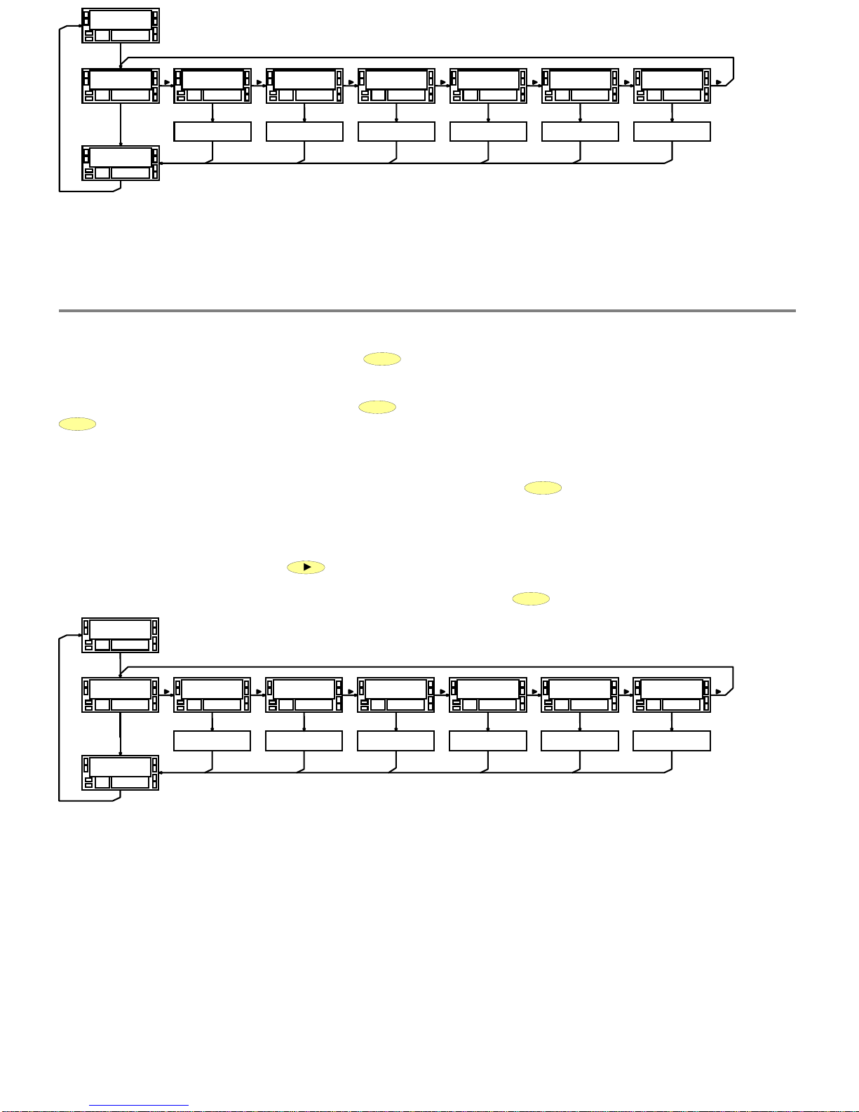
and finally enters in the normal reading mode. Pres
s
ENTER
to enter in the programming mode. The second display shows the
indication "-Pro-" (fig. 13.1).
Exit from the programming mode without saving data
From any step of the program routines, a press on
ESC
r
eturns the meter to the -Pro
-
stage. From this point, a new press of
ESC
shows momentarily the indication "qUIt" on the second display and the instrument enters in the run mode. Any change
is discarded by exiting in this mode.
Save
changes in the configuration
In the programming mode, the instrument returns to the -
Pro-stage at the end of each program menu. The data changes are
not saved at this point, to keep changes in the configuration parameters press
ENTER
, the second display shows momentarily
the indication "StorE" while the new configuration is saved in the memory. After the instrument returns to the run mode.
Guidelines on programming instructions
The programming software is divided into 6 modules. Each module is or
g
anized in several independently accessible menus and
each menu contains a list of parameters necessary to configure a specific function of the meter.
From the -
Pro
- stage, press repeatedly
to cycle around the existing modules : module 10 = Input configuration, module
20 = dis
play
configuration, module 30 (if option installed) = setpoints, module 40 (if option installed) = analog output, module
50 (if option installed) = serial outputs and module 60 = logic functions. Press
ENTER
to access selected module.
fig. 13.1
: Upper level (module selection)
Access to the programming mode
When power is applied to the instrument, the display briefly illuminates all segments and LED's then shows the software version
and finally enters in the normal reading mode. Press
ENTER
to enter in the programming mode. The second di
splay shows the
indication "-Pro-" (fig. 13.1).
Exit from the programming mode without saving data
From any step of the program routines, a press on
ESC
returns the meter to the -Pro
-
stage. From this point, a new press of
ESC
shows momentarily the indication "qUIt" on the second display and the instrument enters in the run mode. Any change
is discarded by exiting in this mode.
Save changes in the configuration
In the programming mode, the instrument returns to the -
Pro-stage at the end of each program menu. The data changes are
not saved at this point, to keep changes in the configuration parameters press
ENTER
, the second display shows momentarily
the indication "StorE" while the new c
onfiguration is saved in the memory. After the instrument returns to the run mode.
Guidelines on programming instructions
The
prog
ramming software is divided into 6 modules. Each module is organized in several independently accessible menus and
each menu c
ontains a list of parameters necessary to configure a specific function of the meter.
From the -
Pro
- stage, press repeatedly
to cycle around the existing modules : module 10 = Input configuration, module
20 = display configuration, module 30 (if option installed) = set
p
oints, module 40 (if option installed) = analog output, module
50 (if option installed) = serial outputs and module 60 = logic functions. Press
ENTER
to access selected module.
fig. 13.1
: Upper level (module s
election)
12
12
2.4.
Programming instructions
8 8 8 8 8 8
8 8
8 8 8 8.8 8
P r o
'ENTER'
S t o r E
C n F I n P
1 0
C n F d S P
2 0
S E t P t S
3 0
A n A o u t
4 0
r S o u
t
5 0
L o G I n P
6 0
'ENTER'
INPUT CONFIGURATION
ROUTINE
DISPLAY CONFIGURATION
ROUTINE
SETPOINTS CONFIGURATION
ROUTINE
ANALOG OUTPUT
CONFIGURATION ROUTINE
RS232C or RS485
CONFIGURATION ROUTINE
LOGIC INPUTS
CONFIGURATION ROUTINE
'ENTER'
'ENTER'
'ENTER'
'ENTER'
'ENTER'
'ENTER'
'ENTER'
'ENTER'
'ENTER'
'ENTER'
'ENTER'
'ENTER'
8 8 8 8 8 8
8 8
8 8 8 8.8 8
P r o
'ENTER'
S t o r E
C n F I n P
1 0
C n F d S P
2 0
S
E t P t S
3 0
A n A o u t
4 0
r S o u t
5 0
L o G I n P
6 0
'ENTER'
INPUT CONFIGURATION
ROUTINE
DISPLAY CONFIGURATION
ROUTINE
SETPOINTS CONFIGURATION
ROUTINE
ANALOG OUTPUT
CONFIGURATION ROUTINE
RS232C or RS485
CONFIGURATION ROUTINE
LOGIC INPUTS
CONFIGURATION ROUTINE
'ENTER'
'ENTER'
'ENTER'
'ENTER'
'ENTER'
'ENTER'
'ENTER'
'ENTER'
'ENTER'
'ENTER'
'ENTER'
'ENTER'
Page 13

13
13
g
g
g
y
p
Moving forward through programming
The advance throu
gh prog
ramming routines is done by
pressings of
ENTER
.
In general, the operations to do on every ste
p
will be press
a number of times to select a option and press
ENTER
to validate the change and go to next programming
step.
The numerical values are
prog
rammed digit to digit as
explained on right paragraph.
Indications
The meter
s configuration is constituted by numerical values
and selectable options.
Generall
y
the parameters value to be selected appears on
main dis
play
, the menus indication and parameter s type
a
pp
ear on secondary display. (The menu number is showed
on two left digits).
The setpoint values or analo
g
output values when referred
to
TOTAL will be programmed using the all digits of
secondar
y
display and the annunciator for this parameter
will be showed on main display.
p
y
p
g
p
g
g
p
y
p
y
will flash one of the left LED
s
The method to program the value is as follow :
Digit select :
Press repeatedly the key
to shift from
left to right through all digits (included LEDs if necessary).
(Digit active flashing).
Change the digit value :
Press repeatedly the key
to increase the digit s value until to get the desired value.
The first
left digit on secondary display will show cyclically
the values from 0 to 9, then the polarity minus (-) and so
on.
On main dis
play
the polarity is programmed with the LEDs
on the left of dis
play
, the upper means positive and the
lower negative.
Option
select from a list
When the
p
arameter has to be select from a list the key
allows us to round all possibilities from the list until
appears on display the desired option.
To access to the programming parameters
Thanks to the tree structure , the programmin
g
routines
allow to access to change any parameter without need of
looking over the whole menu.
Moving forward through programming
The advance throu
gh prog
ramming routines is done by
pressings of
ENTER
.
In general, the operations to do on every step will be
p
ress
a number of times to select a option and press
ENTER
to validate the change and go to next programming
step.
The numerical values are
prog
rammed digit to digit as
explained on right paragraph.
Indications
The meter
s configuration is constituted by numerical values
and selectable options.
Generall
y
the parameters value to be selected appears on
main dis
play
, the menus indication and parameter s type
a
pp
ear on secondary display. (The menu number is showed
on two left digits).
The setpoint values or analo
g
output values when referred
to
TOTAL will be programmed using the all digits of
secondar
y
display and the annunciator for this parameter
will be showed on main display.
Programming numerical values
When the parameter has to be a numerical value, the
dis
play
will put the first digit to be programmed flashing.
On main dis
play
, if the variable can have polarity indication
will flash one of the left LED
s
The method to program the value is as follow :
Digit select :
Press repeatedly the key
to shift from
left to right through all digits (included LEDs if necessary).
(Digit active flashing).
Change the digit value :
Press repeatedly the key
to increase the digit s value until to get the desired value.
The first left di
g
it on secondary display will show cyclically
the values from 0 to 9, then the polarity minus (-) and so
on.
On main dis
play
the polarity is programmed with the LEDs
on the left of dis
play
, the upper means positive and the
lower negative.
Option se
lect from a list
When the
p
arameter has to be select from a list the key
allows us to round all possibilities from the list until
appears on display the desired option.
Page 14

14
14
point and multiplier factor apart from other options related with this configuration.
SECTION 4. Tachometer configuration
, where is described how to scal
e the tachometer and related display options.
SECTION 5. Batch counter configuration
, where is described the way of working and its programming method.
1./
The section 3 has to be read compulsorily in order to know the basic programming of the meter for any configuration
(counter or tachometer), this is to say, selection of number of channels (see point 2.6.) and counter options / totalizer.
2./
Subsequently, if it s wanted to change the counter on main display by a indication of speed (flow, tach. etc...), will be
necessary to activate the option tachometer (section 4).
Configuration 1 CHANNEL
The combination of input A and input B results in only one variable PROCESS (
ProC
) and only one variable TOTAL (
tot
)
Without option Tachometer
COUNTER UNIDI RECTI ONAL WITH I NHI BITI ON
INPUT OR BIDIRECTIONAL WITH TOTALIZER
(+ BATCH COUNTER OPTIONAL)
The countin
g
of number of pulses is done according to th
e
input A and B combination. On main display is shown th
e
partial counting value with polarity (
ProC
) and on
secondary display the TOTAL value with polarity (
tot
).
If added the batch function , on main dis
play
will be shown
the PROCESS (
ProC
) or the batch counter (variable BATCH
btCH
) according to the selection done by key.
With option
Tachometer
TACHOMETER WITH TOTALIZER AND
ROTATING DIRECTION INDICATION
The velocit
y
measurement is done from of frequency o
f
pulses on input A and is shown on main display (
ProC
).
The measurement of total number of
p
ulses is don
e
according to the
inputs A and B combination and is shown
on secondary display. If the combination of A and B give
s
bidirectional counting, the polarity of main display show
s
the rotary direction.
2.5.
Quick programming guide
2.6. Summary of working modes and their programming
Input and display programming instructions are divided into three sections :
SECTION 3. Counter configuration, where is described how to program number of channels, counting method , decimal
point and multiplier factor apart from other options related with this configuration.
SECTION 4. Tachometer configuration
, where is described how to scale the tachometer and related display options.
SECTION 5. Batch counter configuration
, where is describe
d the way of working and its programming method.
1./
The section 3 has to be read compulsorily in order to know the basic programming of the meter for any configuration
(counter or tachometer), this is to say, selection of number of channels (see point 2
.6.) and counter options / totalizer.
2./
Subsequently, if it s wanted to change the counter on main display by a indication of speed (flow, tach. etc...), will be
necessary to activate the option tachometer (section 4).
Configuration 1 CHANNEL
The c
ombination of input A and input B results in only one variable PROCESS (
ProC
) and only one variable TOTAL (
tot
)
Without option Tachometer
COUNTER UNIDI RECTI ONAL WITH I NHI BITI ON
INPUT OR BIDIRECTIONAL WITH TOTALIZER
(+ BATCH COUNTER OPTIONAL)
Th
e counting of number of pulses is done according to th
e
input A and B combination. On main display is shown th
e
partial counting value with polarity (
ProC
) and on
secondary display the TOTAL value with polarity (
tot
).
If added the batch function
, on main display will be shown
the PROCESS (
ProC
) or the batch counter (variable BATCH
btCH
) according to the selection done by key.
With option Tachometer
TACHOMETER WITH TOTALIZER AND
ROTATING DIRECTION INDICATION
The velocity measurement is done from of fre
q
uency o
f
pulses on input A and is shown on main display (
ProC
).
The measurement of total number of
p
ulses is don
e
according to the inputs A and B combination and is shown
on secondary display. If the combination of A and B give
s
bidi
rectional counting, the polarity of main display show
s
the rotary direction.
2.5.
Quick programming guide
2.6. Summary of workin
g modes and their programming
Page 15

15
15
One arithmetical function between
ProC
-A and
ProC
-b generates the
ProC
-C variable and the same function between
tot
-A and
tot
-b generates the
tot-C
variable.
Applications :
Without tachometer option
1 COUNTER UNIDIRECTIONAL WITH TOTALIZER
(+ BATCH COUNTER OPTIONAL) PLUS
1 COUNTER UNIDIRECTIONAL WITH TOTALIZER
(+ BATCH COUNTER OPTIONAL) PLUS
1 COUNTER WITH TOTALIZER (+ BATCH COUNTER
OPTIONAL) AS A RESULT OF ARI THMETICAL
FUNCTION BETWEEN THE TWO PREVIOUS.
From in
p
ut A counts the number of pulses that will increas
e
(or decrease) a partial counter (
ProC
-A) and a total (
tot
-
A
). If it s added a batch option, a third variable will b
e
generated
btCH
-A.
In a se
p
arate way, the pulses on input B will increase (o
r
decrease) the variables
ProC
-b and
tot
-b . If it s added
the batch option, will be generated a third variabl
e
btCH
-b .
As a result of arithmetical function between the in
p
ut A and
B variables will have a third channel
ProC
-C,
tot
-C and,
in case exists a batch in both A
y
B channel, the variabl
e
btCH
-C.
With tachometer option
1 COUNTER UNIDIRECCIONAL WITH TOTALIZER
(+ BATC
H COUNTER OPTIONAL) AND
1 TACHOMETER WITH TOTALIZER AND
1 TOTALI ZER AS A RESULT OF ARI THMETICAL
OPERATION BETWEEN THE TWO PREVIOUS.
The measurement of the velocity is done from the frequency
of the pulses on input A and generates the variable
ProC
-A
That will be show on main dis
play
. The total number o
f
pulses applied at this input generates the variable
tot
-A
that will be show on auxiliary display.
Inde
p
endiently, from input B are counted the number o
f
pulses to generate a partial counter
ProC-band a total
total
tot
-b . If is added the option batch, will generate
a
third variable
btCH
-b .
On the virtual channel only exists a varaible
tot
-C that i
s
the result of an arithmetical function between
tot-Aand
tot
-B .
3 CHANNEL configuration
INPUT A generates PROCESS variable (
ProC
-A) and TOTAL (
tot
-A).
INPUT B generates PROCESS variable (
ProC
-b ) and TOTAL (
tot
-b ).
One arithmetical function between
ProC
-A and
ProC
-b generates the
ProC
-C variable and the same function between
tot
-A and
tot
-b generates the
tot-C
variable.
Applications :
Without tachometer option
1 COUNTER UNIDIRECTIONAL WITH TOTALIZER
(+ BATCH COUNTER OPTIONAL) PLUS
1 COUNTER UNIDIRECTIONAL WITH TOTALIZER
(+ BATCH COUNTER OPTION
AL) PLUS
1 COUNTER WITH TOTALIZER (+ BATCH COUNTER
OPTIONAL) AS A RESULT OF ARI THMETICAL
FUNCTION BETWEEN THE TWO PREVIOUS.
From in
p
ut A counts the number of pulses that will increas
e
(or decrease) a partial counter (
ProC
-A) and a total (
tot
-
A
). If it s added a batch option, a third variable will b
e
generated
btCH
-A.
In a se
p
arate way, the pulses on input B will increase (o
r
decrease) the variables
ProC
-b and
tot
-b . If it s added
the batch option, will be generated a third variabl
e
btCH
-b .
As a result of arithmetical function between the in
p
ut A and
B variables will have a third channel
ProC
-C,
tot
-C and,
in case exists a batch in both A
y
B channel, the variabl
e
btCH
-C.
With tachometer option
1 COUNTER UNIDIRECCIONAL WITH TOTAL
IZER
(+ BATCH COUNTER OPTIONAL) AND
1 TACHOMETER WITH TOTALIZER AND
1 TOTALI ZER AS A RESULT OF ARI THMETICAL
OPERATION BETWEEN THE TWO PREVIOUS.
The measurement of the velocity is done from the frequency
of the pulses on input A and generates the variab
le
ProC
-A
That will be show on main dis
play
. The total number o
f
pulses applied at this input generates the variable
tot
-A
that will be show on auxiliary display.
Inde
p
endiently, from input B are counted the number o
f
pulses to generate a partial counter
ProC
-b and a total
total
tot
-b . If is added the option batch, will generate
a
third variable
btCH
-b .
On the virtual channel only exists a varaible
tot
-C that i
s
the result of an arithmetical function between
tot-Aand
tot
-B .
Page 16

16
16
SECTION
Pág.
3.1.
Definitions
18
3.2.
Input and display programming diagram
19
3.3.
Input programming
3.3.1. 1 channel - 3 channels selection
20
3.3.2. Counting m
ethods
21-22
3.3.3. Arithmetical functions. Channel C
23
3.3.4. Additional options. Counting edge and filter
24
3.4.
Display programming
3.4.1. Scale. Decimal point and multiplier factor
25
3.4.2. Offset
26
3.5.
Notes for 3 channel counter diagram
26
SECTION
Pág.
3.1.
Definitions
18
3.2.
Input and display programming diagram
19
3.3.
Input programming
3.3.1. 1 channel - 3 channels selection
20
3.3.2. Counting methods
21-22
3.3.3. Arithmetical functions. Channel C
23
3
.3.4. Additional options. Counting edge and filter
24
3.4.
Display programming
3.4.1. Scale. Decimal point and multiplier factor
25
3.4.2. Offset
26
3.5.
Notes for 3 channel counter diagram
26
3.
COUNT
ER WITH TOTALIZER
Index
Page 17

17
17
3.1. Glossary
g
corres
p
onds to the input pulse measurement multiplied by a
factor.
The PROCESS variable is shown on main display
TOTAL Variable
Is the total of pulses accumulated at the rate of the main
variable without taking into account the actions that can
produce over it a change of value (reset, load).
The TOTAL variable will alwa
y
s show the number of pulses
detected multiplied by a factor.
The TOTAL variable will be shown on secondary display.
C
hannel
A channel is the set of measures done and related to the
variables (PROCESS, TOTAL) to every one of the input or its
combination
1 Channel Counter
It is a counter configuration where the two inputs are joined
to form an only set of PROCESS and TOT
AL variables.
In
g
eneral the input A is used like a main input meanwhile
the in
p
ut B can be used like an active input or inhibit input
or direction input.
This combination allows to
g
et bidirectional counters (up
and down).
This confi
g
uration allows to count in a separate way the
p
ulses on input A and the pulses on input B giving as a
result
three independent set of variables PROCESS and
TOTAL; one for each input (Channel A and Channel B) and a
third channel like a result of arithmetical operation between
the two previous (Channel C).
In this configuration, every input is used to count in on
e
direction (up or down) and it doesn t exist input for direction
sense for that is not possible to have bidectional counting.
Channel C (Only on 3 channels configuration)
The channel C is a result of an arithmetical o
p
eration
between the display values o
f channel A and B.
The arithmetical function is done with the visible
p
art of
counters A and B, not bein
g
counted the decimal hidden
part of them.
It is not refreshed the value at ever
y p
ulse but at 10ms
intervals.
On power-up, the variable C is charged with the
corresponding value according to the relation of A and B.
The reset done on one variable of channel C makes a reset
on variables A and B.
The set
p
oint options related to some variable of channel C
will have a 10ms response time minimum.
3.1. Glossary
PROCESS Variable
Is the main variable that in case of counter confi
g
uration
corresponds to the input pulse measurement multiplied by
a
factor.
The PROCESS variable is shown on main display
TOTAL Variable
Is the total of
p
ulses accumulated at the rate of the main
variable without takin
g
into account the actions that can
produce over it a change of value (reset, load).
The TOTAL variable
will always show the number of pulses
detected multiplied by a factor.
The TOTAL variable will be shown on secondary display.
Channel
A channel is the set of measures done and related to the
variables (PROCESS, TOTAL) to every one of the input or its
co
mbination
1 Channel Counter
It is a counter configuration where the two inputs are joined
to form an only set of PROCESS and TOTAL variables.
In
g
eneral the input A is used like a main input meanwhile
the input B can be used like an active input or inhibit in
p
ut
or direction input.
This combination allows to
g
et bidirectional counters (up
and down).
3 Channe
ls Counter
This confi
g
uration allows to count in a separate way the
p
ulses on input A and the pulses on input B giving as a
result three inde
p
endent set of variables PROCESS and
TOTAL; one for each input (Channel A and Channel B) and a
third channel like a result of arithmetical operation between
the two previous (Channel C).
In this confi
g
uration, every input is used to count in one
direction (u
p
or down) and it doesn t exist input for direction
sense for that is not possible to have bidectional counting.
Channel C (Only on 3 channels configuration)
The channel C is a result of an arithmetical o
p
eration
between the display values of channel A and B.
The arithmetical function is done with the visible
p
art of
counters A and B, not being counted the decimal
hidden
part of them.
It is not refreshed the value at ever
y p
ulse but at 10ms
intervals.
On power-u
p
, the variable C is charged with the
corresponding value according to the relation of A and B.
The reset done on one variable of channel C makes a reset
on
variables A and B.
The set
p
oint options related to some variable of channel C
will have a 10ms response time minimum.
Page 18
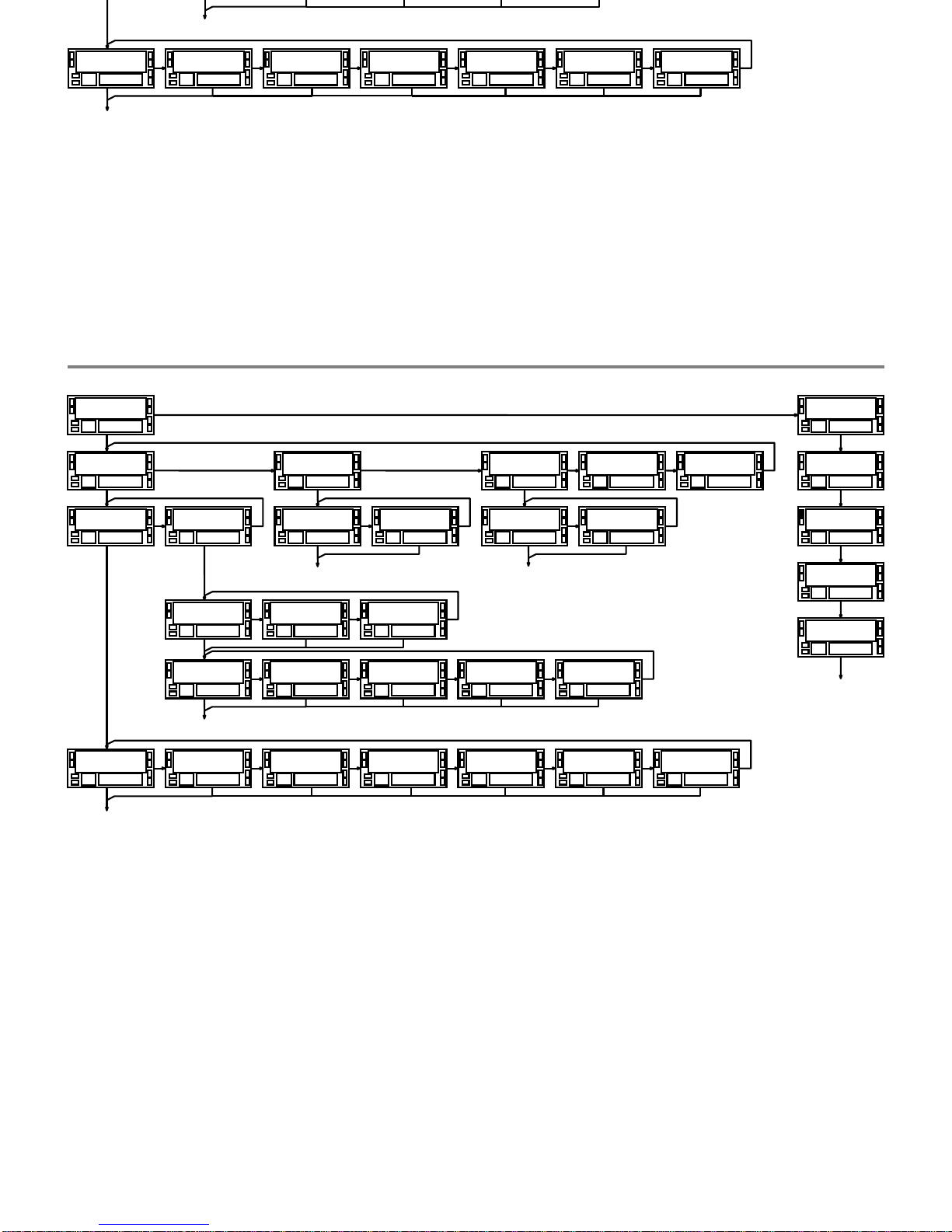
18
18
3.2. Input and display configuration diagram
3.2. Input and display configuration diagram
M o d E
1 1
E d G E
1 2
F I L t
1 3
C H A n n
1 1
1
C H A n n
1 1
3
E d G E
1 2
1
E d G E
1 2
2
F I L t
1 3
n o
F I L t
1 3
Y E S
C n F I n P
1 0
M o d E
1 1
u P - d o
M o d E
1 1
u P - i n H
M o d E
1 1
d o - i n H
M o d E
1 1
d I r
M o d E
1 1
P H 1
M o d E
1 1
P H 2
M o d E
1 1
P H 4
PRO
PRO
PRO
M o d
E
1 1
u P - u P
M o d E
1 1
u P - d o
M o d E
1 1
d o - d o
F u n C
1 1
A d d
F u n C
1 1
S u b s
F u n C
1 1
M u L t
F u n C
1 1
d I V
F u n C
1 1
o / o
PRO
C n F d S P
2 0
d E C P
2 1
0 0 0 0 0.0
F A C t
2 1
0 9 9 9 9
o F F S
2 1
9 9 9 9 9.9
r A t E
1 4
b t C H
1 5
F A C t
2 1
0 9 9 9.9
PRO
M o d E
1 1
E d G E
1 2
F I L t
1 3
C H A n n
1 1
1
C H A n n
1 1
3
E d G E
1 2
1
E d G E
1 2
2
F I L t
1 3
n o
F I L t
1 3
Y E S
C n F I n P
1 0
M o d E
1 1
u P - d o
M o d E
1 1
u P - i n H
M o d E
1 1
d o - i n H
M o d E
1 1
d I r
M o d E
1 1
P H 1
M o d E
1 1
P H 2
M o d E
1 1
P H 4
PRO
PRO
PRO
M o d E
1 1
u P - u P
M o d E
1 1
u P - d o
M o d E
1 1
d o - d o
F u n C
1 1
A d d
F u n C
1 1
S u b s
F u n C
1 1
M u L t
F u n C
1 1
d I V
F u n C
1 1
o / o
PRO
C n F d S P
2 0
d E C P
2 1
0 0 0 0 0.0
F A C t
2 1
0 9 9 9 9
o F F S
2 1
9 9 9 9 9.9
r A t E
1 4
b t C H
1 5
F A C t
2 1
0 9 9 9.9
PRO
Page 19
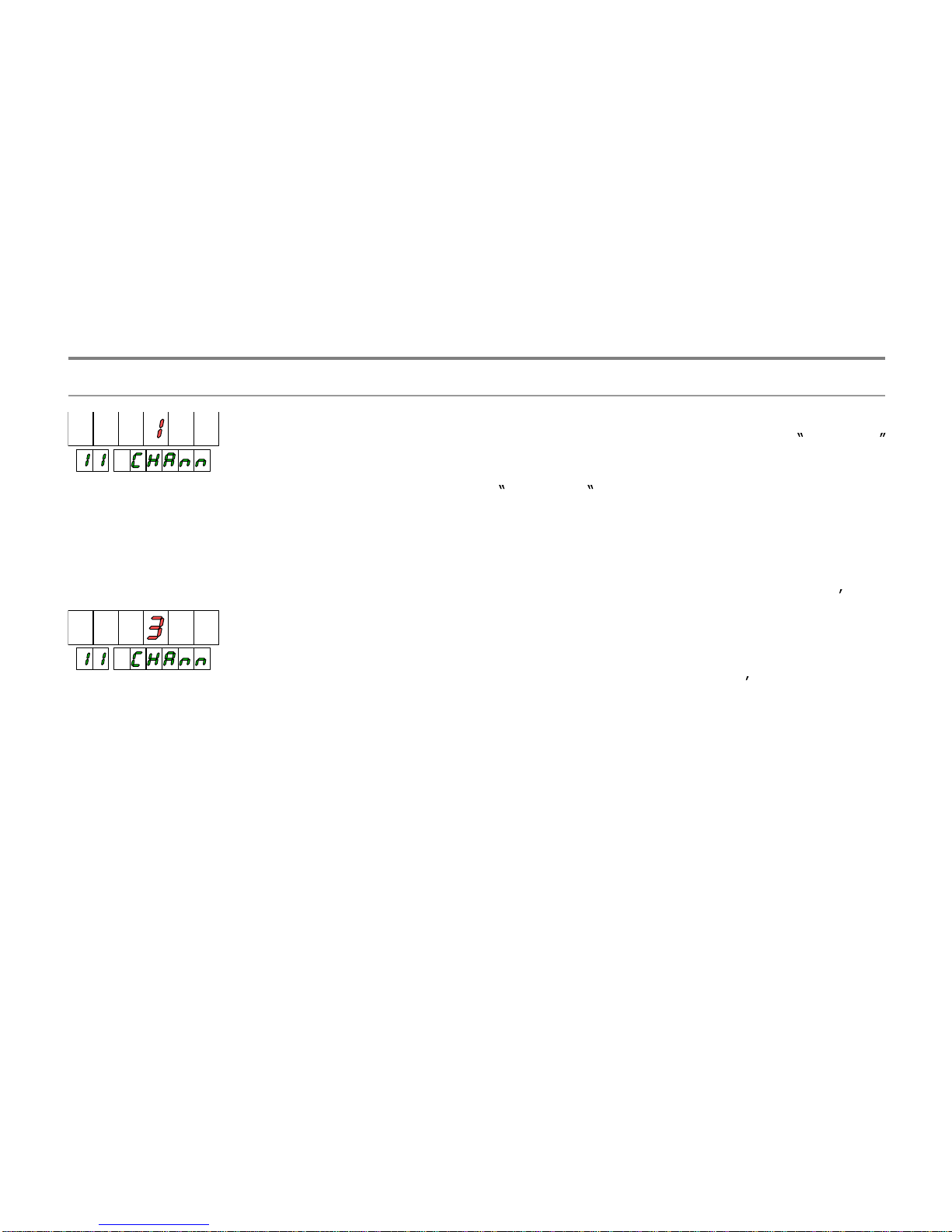
19
19
1 CHANNEL.
The 1 channel configuration is the basic
mode of counter where at least one of the in
p
ut acts as a
pulse input and the other like a counting direction, inhibition
or like a pulse input to count in reverse direction of the
main input.
3 CHANNELS.
In 3 channels configuration, the pulses at
ever
y
input increase or decrease two independent counters
(one for each input)
To have a bidirectional counter, this is to sa
y
, able to count
and discount, it should be
prog
rammed with 1 CHANNEL
option.
To
have 2 independent counts, should be programmed with
3 CHANNEL
option.
Example :
Measurement of the number of cars throu
g
h the entrance
and throu
g
h the exit in a parking, to know how many cars
remain inside.
With 1 channel configuration, using one of
the meters input
to count the cars through the entrance and the other to
discount what are going out (up-do Mode) at ever
y
instant
we know how man
y
cars remain inside the parking. If there
is a offset
prog
rammed (see p. 26) as a number of free
places and
inverting the inputs, well have always the
indication of remaining free places.
Selectin
g
3 channel configuration, we should know the
number of cars that have entered into the
p
arking during a
period of time (since last reset) on counter A, the number o
f
cars that have exited from the parking on counter B and,
prog
ramming the arithmetical function subtraction (SubS)
between A and B, the counter C will show in all moment the
number of cars inside of parking.
3.3
3 channels selection
3.3. Input programming
1 CHANNEL.
The 1 channel configuration is the basic
mode of counter where at least one of the input acts as a
pulse input and the other like a counting direction, inhibition
or like a pulse input to count in reverse direction of the
main input.
3 CHANNELS.
In 3 channels configuration, the pulses at
every input increase or decrease two inde
p
endent counters
(one for each input)
To have a bidirectional counter, this is to say, able to count
and discount, it should be
prog
rammed with 1 CHANNEL
option.
To have 2 inde
p
endent counts, should be programmed with
3 CHANNEL
option.
Example :
Measurem
ent of the number of cars through the entrance
and through the exit in a parking, to know how many cars
remain inside.
With 1 channel confi
g
uration, using one of the meters input
to count the cars throu
g
h the entrance and the other to
discount what are going out (up-do Mode) at ever
y
instant
we know how man
y
cars remain inside the parking. If there
is a offset
prog
rammed (see p. 26) as a number of free
p
laces and inverting the inputs, we ll have always the
indication of remaining free places.
Selecting 3 channel confi
g
uration, we should know the
number of cars that have entered into the
p
arking during a
period of time (since last reset) on counter A, the number of
cars that have exited from the parking on counter B and,
programming the arithmetical function subtraction (SubS)
between A and B, the counter C will show in all moment the
number of cars inside of parking.
3.3
.1. 1 chan
nel
-
3 channels selection
3.3. Input programming
Page 20
20
20
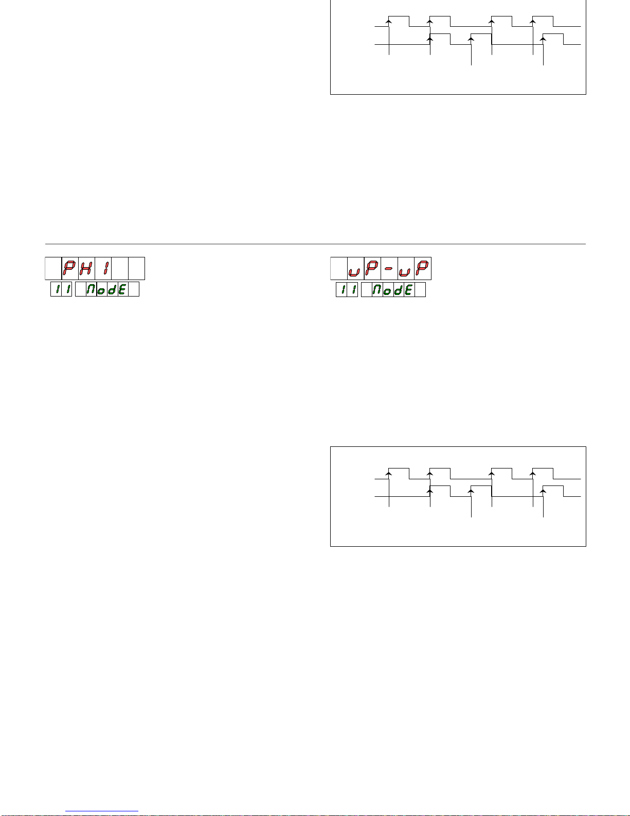
CONFIGURATION 1 CHANNEL
uP-do Adds input A and input B subtracts.
up-inh Adds input A if input B is low.
Input B is used like inhibition input.
do-inh Subtracts A if input B is low.
Input B is used like inhibition input.
dir
Adds input A and subtracts if B is high. Input B is
used like a direction input.
PH1
Adds input A rising edge when input B is low
subtracts input A falling edge when input B is low.
PH2 Adds input A rising edge if B is low
Subtracts input A rising edge if input B is high.
Adds input A falling edge if B is high
Subtracts input A falling edge if input B is low.
PH4 Adds input A rising edge if B is low
Subtracts input A rising edge if input A is high.
Adds input B rising edge if B is low
Subtracts input A rising edge if
input B is high.
Adds input A falling edge if B is high
Subtracts input A falling edge if input B is low.
Adds input B falling edge if A is low
Subtracts input B falling edge if input A is high.
CONFIGURATION 3 CHANNELS
up-up Input A increases the counter A.
Input B increases the counter B.
up-do Input A increases the counter A.
Input B decreases the counter B.
do-do Input A
decreases the counter A.
Input B decreases the counter B.
Like exam
p
le the diagram shows a counter programmed
up
-up, considering that Channel C is the additions of
channels A & B
See arithmetical functions on p. 23
MODE UP-UP. func
tion Add
process A
channel B
channel A
2
process B
process C
1 53 64 7
1 3
21
4
3
3.2.
Counting methods
CONFIGURATION 1 CHANNEL
uP-do Adds input A and input B subtracts.
up-inh Adds input A if input B is low.
Input B is used like inhibition input.
do-inh Subtracts A if input B is low.
Input B is used like inhibition input.
dir
Adds input A and subtracts if B is high. Input B is
used like a direction input.
PH1
Adds input A rising edge when input B is low
subtracts input A falling edge when input B is low.
PH2 Adds input A rising edge if B is low
Subtracts input A rising edge if input B is high.
Ad
ds input A falling edge if B is high
Subtracts input A falling edge if input B is low.
PH4 Adds input A rising edge if B is low
Subtracts input A rising edge if input A is high.
Adds input B rising edge if B is low
Subtracts input A rising edge if in
put B is high.
Adds input A falling edge if B is high
Subtracts input A falling edge if input B is low.
Adds input B falling edge if A is low
Subtracts input B falling edge if input A is high.
CONFIGURATION 3 CHANNELS
up-up Input A increases the counter A.
Input B increases the counter B.
up-do Input A increases the counter A.
Input B decreases the counter B.
do-do Input A d
ecreases the counter A.
Input B decreases the counter B.
Like exam
p
le the diagram shows a counter programmed
up
-up, considering that Channel C is the additions of
channels A & B
See arithmetical functions on p. 23
MODE UP-UP. functi
on Add
process A
channel B
channel A
2
process B
process C
1 53 64 7
1 3
21
4
3
3.2.
Counting methods
Page 21
21
21
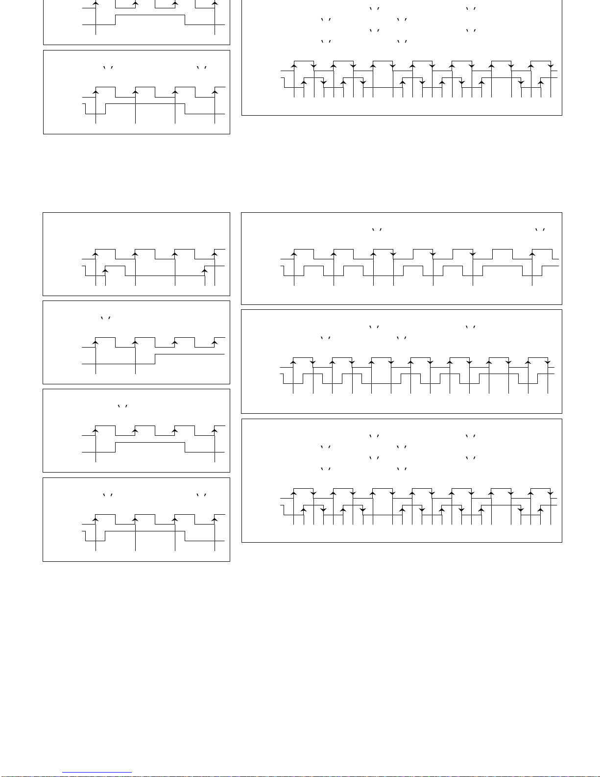
1 2 3 2 1 0 1
process
channel B
channel A
1 1 2 1
process
channel B
channel A
0 2
MODE PH2
Adds input A rising edge if B is
0 and subtracts if B is 1 . Subtracts input A
falling edge if B is
0 and adds if B is 1.
1 3 5 4 2 0 1
process
channel B
channel A
2 4 3 1 0
-1
2
MODE UP-INH
A Adds if B is
0. B inhibit counting.
1 2
process
channel B
channel A
MODE PH4
Adds i
nput A rising edge if B is 0 and subtracts if B is 1 . Subtracts input A
falling edge if B is
0 and adds if B is 1.
Adds input B rising edge if A is
1 and subtracts if A is 0. Subtracts input B
falling edge if A is
1 and adds if A is 0.
1 5 9 8 4 0 1
process
channel B
channel A
3 7 6 2
-1-2
32 4 6 8 7 5 3 1
-1
0 2
MODE DO-INH
A subtracts if B is
0. B inhibit counting.
-1
process
channel B
channel A
-2
MODE DIR
A adds if B is
0 and subtracts if B is 1 .
1 0
-1
process
channel B
channel A
0
MODE PH1
Adds input A rising edge if B is
0. Subtracts input A falling edge if B is 0 .
1 2 3 2 1 0 1
process
channel B
channel A
MODE UP-DO
A Adds. B Subtracts
1 1 2 1
process
channel B
channel A
0 2
MODE PH2
Adds input A rising edge i
f B is 0 and subtracts if B is 1. Subtracts input A
falling edge if B is
0 and adds if B is 1.
1 3 5 4 2 0 1
process
channel B
channel A
2 4 3 1 0
-1
2
MODE UP-INH
A Adds if B is
0. B inhibit counting.
1 2
process
channel B
channel A
MODE PH4
Adds input A rising edge if B is
0 and subtracts if B is 1 . Subtracts input A
falling edge if B is
0 and adds if B is 1.
Adds input B rising edge
if A is 1 and subtracts if A is 0. Subtracts input B
falling edge if A is
1 and adds if A is 0.
1 5 9 8 4 0 1
process
channel B
channel A
3 7 6 2
-1-2
32 4 6 8 7 5 3 1
-1
0 2
MODE DO-INH
A subtracts if B is
0. B inhibit counting.
-1
process
channel B
channel A
-2
MODE DIR
A adds if B is
0 and subtracts if B is 1 .
1 0
-1
process
channel B
channel A
0
Page 22
22
22
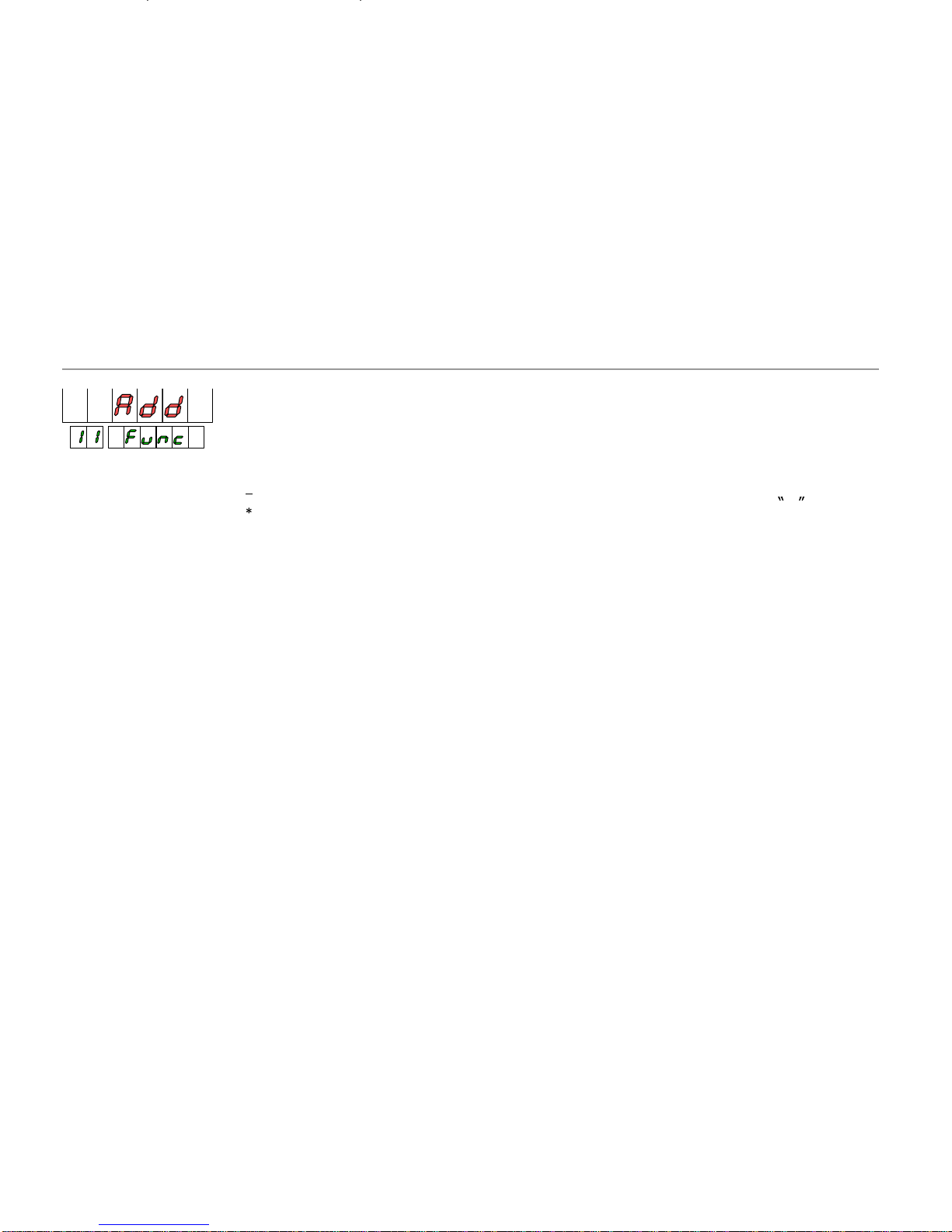
Add Addition
A + B
SubS Subtraction
A B
MuLt Multiplication A B
diV
Division
A / B
o/o
Percentage
A / (A + B)
When the counter is three channels,
The operation is done between the display values,
never with the internal registe
rs, for that, if exits
some hidden decimal fraction on variables A and B,
this will be not considered.
Example : Assumed that the display has no decimal point
and the multiplier factor is 0,5. The channel A process value
is 10,5 but the display shows 10, t
he channel B value is 2,5
and the display shows 2.
If the arithmetical function is addition, the channel C value
will be 12 instead 13 because of the hidden decimal part.
The channel C is the
result of an arithmetical operation
between channels A and B.
The arithmetical function is done with the whole figure on
display disregarding the hidden decimals.
When the selected arithmetical function is % (A/(A+B)),
the C variable is shown with a dec
imal point and reaches a
maximum value of 99.9 except for B=0, that is 100.0.
This channel is not updated at every pulse but a intervals of
10ms.
The setpoint output option related to any variable of
channel C the response time will be aprox. 10ms.
After
power-
up, the C variables are loaded with the
corresponding value according to the relation between A
and B.
The reset function done over a C variable will make a
reset of variables A and B.
The Load function has no effect on C counter.
3.3.3. Arithmetical functions. Channel C
Add Addition
A + B
SubS Subtraction
A B
MuLt Multiplication A B
diV
Division
A / B
o/o
Percentage
A / (A + B)
When the counter is three channels,
The operation is done between the display values,
never with the internal registers, for th
at, if exits
some hidden decimal fraction on variables A and B,
this will be not considered.
Example : Assumed that the display has no decimal point
and the multiplier factor is 0,5. The channel A process value
is 10,5 but the display shows 10, the channel
B value is 2,5
and the display shows 2.
If the arithmetical function is addition, the channel C value
will be 12 instead 13 because of the hidden decimal part.
CHANNEL C. Characteristics
The channel C is the result of
an arithmetical operation
between channels A and B.
The arithmetical function is done with the whole figure on
display disregarding the hidden decimals.
When the selected arithmetical function is % (A/(A+B)),
the C variable is shown with a decimal point
and reaches a
maximum value of 99.9 except for B=0, that is 100.0.
This channel is not updated at every pulse but a intervals of
10ms.
The setpoint output option related to any variable of
channel C the response time will be aprox. 10ms.
After power-
up,
the C variables are loaded with the
corresponding value according to the relation between A
and B.
The reset function done over a C variable will make a
reset of variables A and B.
The Load function has no effect on C counter.
3.3.3. Arithmetical functions. Channel C
Page 23
23
23
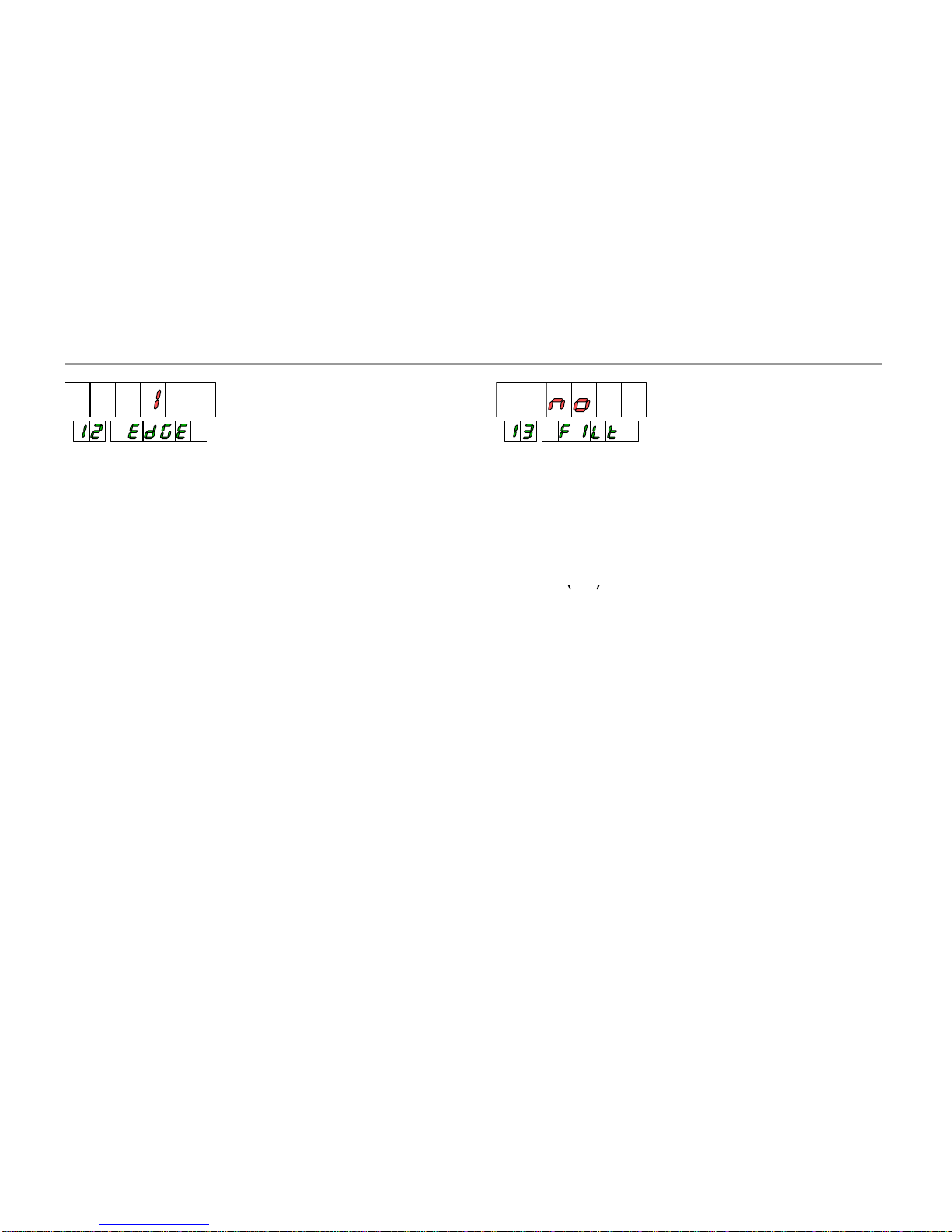
1
Counting on rising edge
2
Counting in both rising and falling edge
COUNTING EDGE.
The counting optio
n using rising and
falling edges of input pulses allows to increase the accuracy
of the maesurement.
This option has no effect on modes PH1, PH2 y PH4.
no
without filter
YES anti-debounce filter 100Hz
ANTI
-DEBOUNCE FI LTER.
When the input signal is
comming from a switch contac or another element that can
produce undesired signals like b
ounces is necesary to
program filter yes to avoid counting errors.
With filter ( YES), the maximum frequency is 100Hz.
3.3.4. Additional Options. Coun
ting edge and anti
-
debounce filter
1
Counting on rising edge
2
Coun
ting in both rising and falling edge
COUNTING EDGE.
The counting option using rising and
falling edges of input pulses allows to increase the accuracy
of the maesurement.
This option has no effect on modes PH1, PH2 y PH4.
no
without filter
YES anti-debounce filter 100Hz
ANTI
-DEBOUNCE FI LTER.
When the input signal is
comming from a swi
tch contac or another element that can
produce undesired signals like bounces is necesary to
program filter yes to avoid counting errors.
With filter ( YES), the maximum frequency is 100Hz.
3.3.4. Additional Options. Counting edge and anti
-
debounce filter
Page 24
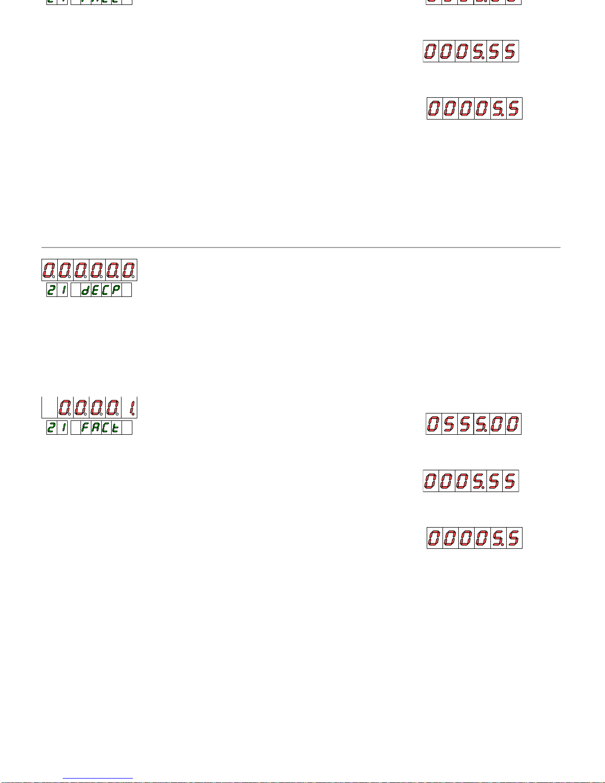
DECIMAL POI NT.
The decimal point position is active,
and limits the display range.
Assumed a multiplier factor
x1, and a display with two
decimal positions, a counting value of 555 will be shown on
display as 555.00. In this conditions the display should entry
in overflow condition from 9999.00 misusing two display
digits.
MULTIPLIER
FACTOR.
The multiplier factor is
programmable between 0.0001 and 9999 with its own
decimal point, for that is possible to get any value in the
range independently of decimal position of display.
The display decimal point and multiplier factor are
commons
for all process and total variables.
On previous paragraph case, a factor of 0.01 should allow
see all input pulses on display maintaining the indication
with two decimals. The counting value 555 would be shown
on the way 5.55.
If with the same fac
tor, the decimal point of the display
shift right one position (factor 0.01, display 00000.0), would
be observed a change of a point of display every 10 entry
pulses and the value of count 555 would be indicated of the
form 5.5.
EXAMPLES :
COUNTING VALUE (
pulses at the input) = 555
MULTIPLIER FACTOR x1
DISPLAY DECIMALS 2 (0000.00)
DISPLAY VALUE
MULTIPLIER FACTOR
x0.01
DISPLAY DECIMALS
2
(0000.00)
DISPLAY VALUE
MULTIP
LIER FACTOR
x0.01
DISPLAY DECIMALS
1
(00000.0)
VALOR DE DISPLAY
DECI MAL POI NT.
The decimal point position is active,
and limits the display range.
Assumed a multiplier factor x1, and a display with two
decimal positions, a counting value of 555 will be s
hown on
display as 555.00. In this conditions the display should entry
in overflow condition from 9999.00 misusing two display
digits.
MULTIPLIER FACTOR.
The multiplier factor is
programmable between 0.0001 and 9999 with its
own
decimal point, for that is possible to get any value in the
range independently of decimal position of display.
The display decimal point and multiplier factor are
commons for all process and total variables.
On previous paragraph case, a facto
r of 0.01 should allow
see all input pulses on display maintaining the indication
with two decimals. The counting value 555 would be shown
on the way 5.55.
If with the same factor, the decimal point of the display
shift right one position (factor 0.01, dis
play 00000.0), would
be observed a change of a point of display every 10 entry
pulses and the value of count 555 would be indicated of the
form 5.5.
EXAMPLES :
COUNTING VALUE (pulses at the input) = 555
MULTIPLIER FACTOR x1
DISPLAY DECIMALS 2 (0000.00)
DI
SPLAY VALUE
MULTIPLIER FACTOR
x0.01
DISPLAY DECIMALS
2
(0000.00)
DISPLAY VALUE
MULTIPLIER FACTOR
x0.01
DISPLAY DECIMALS
1
(00000.0)
VALOR DE DISPLAY
242
4
3.4. Display configuration
3.4.1. Scaling. Decimal point and multipl
ier factor
3.4.1. Scaling. Decimal point and multiplier factor
Page 25
25
25
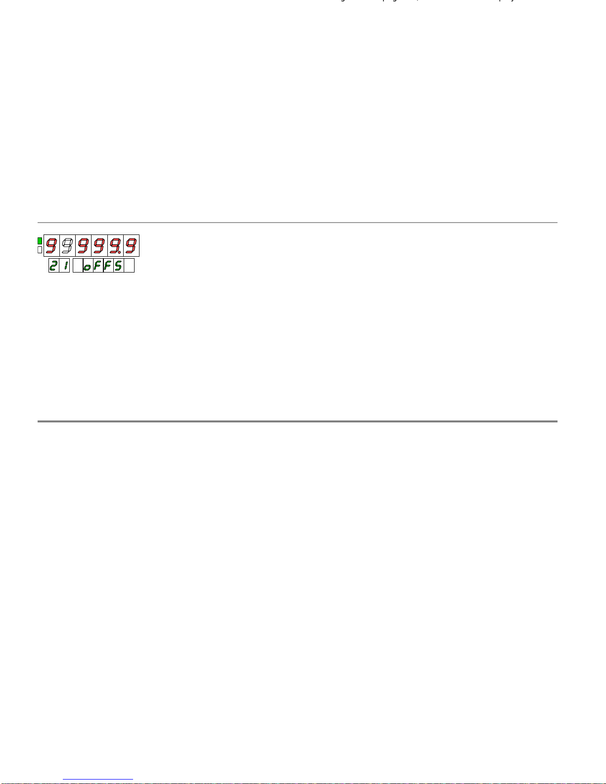
OFFSET.
Offset is the value of beginning of a cycle of
counting, that is to say, the value that takes the display
when a reset is done.
By default, the value of beginning of counter is zero in any
of its configurations.
Only the process variables (main display) can
have offset,
except Process-C if the counter is of 3 channels.
The decimal point of the display is the same for all the
variables PROCESS and TOTAL of both channels.
There is a value of factor multiplier for the channel A and
another different valu
e for the channel B but with the
decimal point in the same position.
There is a value of offset for the channel A and another
different value for the channel B.
In a reset of the process, the totalizer is not increased with
the value of offset. The totalizer accumulates the quantity of
impulses of entry (multiplied by a factor) independen
tly of
what action it takes place in the display process. He does
not remain affected by the quantities added to the main
display that are not a consequence of an impulse in the
input.
On diagram of page 19, the module of display has been
represented
for the case of which the counter is of 1
channel.
If the counter was of 3 channels, two values would exist of
offset programmable (oFFS -A and oFFS-
b) and two factors
multipliers (FACt -A and FACt-
b). The decimal point of the
factor is programmed for the
channel A and the position is
the same when is programmed the factor of the channel B.
3.4.2. Offset
3.5. Diagram notes (3 channels counter)
OFFSET.
Offset is the valu
e of beginning of a cycle of
counting, that is to say, the value that takes the display
when a reset is done.
By default, the value of beginning of counter is zero in any
of its configur
ations.
Only the process variables (main display) can have offset,
except Process-C if the counter is of 3 channels.
The decimal point of the display is the same for all the
variables PROCESS a
nd TOTAL of both channels.
There is a value of factor multiplier for the channel A and
another different value for the channel B but with the
decimal point in the same position.
There is a value of offset for the channel A and another
different value for t
he channel B.
In a reset of the process, the totalizer is not increased with
the value of offset. The totalizer accumulates the quantity of
impulses of ent
ry (multiplied by a factor) independently of
what action it takes place in the display process. He does
not remain affected by the quantities added to the main
display that are not a consequence of an impulse in the
input.
On diagram of page 19, the m
odule of display has been
represented for the case of which the counter is of 1
channel.
If the counter was of 3 channels, two values would exist of
offset programmable (oFFS -A and oFFS-
b) and two factors
multipliers (FACt -A and FACt-b). The decimal poin
t of the
factor is programmed for the channel A and the position is
the same when is programmed the factor of the channel B.
3.4.2. Offset
3.5. Diagram notes (3 channels counter)
Page 26

26
26
SECTION
4.1.
Definitions
28
4.2.
Input and display programming diagram
29
4.3.
Input programming
4.3.1. Tachometer selection and scaling
30
4.3.2. Examples
31
4.4.
Display programming
4.4.1. Special functions for measuring frequency
32
4.4.2. Display options for the totali
zer
33
4.5.
Diagram notes for 3 channel counter
34
4. TACHOMETER WITH TOTALIZER
Index
SECTION
4.1.
Definitions
28
4.2.
Input and display programming diagram
29
4.3.
Input programming
4.3.1. Tachometer selection and scaling
30
4.3.2. E
xamples
31
4.4.
Display programming
4.4.1. Special functions for measuring frequency
32
4.4.2. Display options for the totalizer
33
4.5.
Diagram notes for 3 channel counter
34
4. TACHOMETER WITH TOTALIZER
Index
Page 27

27
27
4.1. Terminology
It is the main variable that, when the option tachometer is
activated
corresponds to the instantaneous speed measured
from the frequency of the impulses of entry.
If the counter is of 3 channels there are two process
variables; in the channel A, the instantaneous speed
measured in the entry A and in the channel B, the numbe
r
of impulses measured in the entry B.
TOTAL variable
It is the whole of impulses accumulated to the rate of the
main variable without having into account the actions that
can produce in this a change of value (reset, load).
The TOTAL variable always will
indicate the number of
detected impulses multiplied by a factor.
Sense of rotation
The indication of sense of rotation only is possible when the
associated counter with the channel of speed measurement
is bidirectional, that is to say, one can count in a
scending
(rising) and descending sense. This condition only is given
in the configuration of 1 channel with the bidirectional
manners of count (uP-do, dIr, PH1, PH2 and PH4).
In the configuration of tachometer, the instantaneous speed
will constitute the variable PROCESS and the number of
impulses for the TOTAL variable.
.
3 Channels counter
In the configuration of tacho
meter, the channel assigned to
the measurement of frequency is the channel A which it will
have the variables associate PROCESS A (instantaneous
speed) and TOTAL A whereas the channel B will be a
counter who will have the variables PROCESS B and TOTAL
B.
T
he channel C will be constituted by the TOTAL variable C
that will be a result of an arithmetical function between the
variables TOTAL A and TOTAL B.
4.1. Terminology
PROCESS variable
It is the main variable that, when the option tachometer is
activated corresponds to the instantaneous speed measured
from the frequency of the impulses of entry.
If the counter is of 3 channels there are two process
variables;
in the channel A, the instantaneous speed
measured in the entry A and in the channel B, the number
of impulses measured in the entry B.
TOTAL variable
It is the whole of impulses accumulated to the rate of the
main variable without having into account the
actions that
can produce in this a change of value (reset, load).
The TOTAL variable always will indicate the number of
detected impulses multiplied by a factor.
Sense of rotation
The indication of sense of rotation only is possible when the
associated c
ounter with the channel of speed measurement
is bidirectional, that is to say, one can count in ascending
(rising) and descending sense. This condition only is given
in the configuration of 1 channel with the bidirectional
manners of count (uP-do, dIr, PH1
, PH2 and PH4).
1 Channel counter
In the configuration of tachometer, the instantaneous speed
will constitute the variable PROC
ESS and the number of
impulses for the TOTAL variable.
.
3 Channels counter
In the configuration of tachometer, the channel assigned to
the measurement of frequency is the channel A which it will
have the variables associate PROCESS A (instantaneous
speed
) and TOTAL A whereas the channel B will be a
counter who will have the variables PROCESS B and TOTAL
B.
The channel C will be constituted by the TOTAL variable C
that will be a result of an arithmetical function between the
variables TOTAL A and TOTAL B.
Page 28
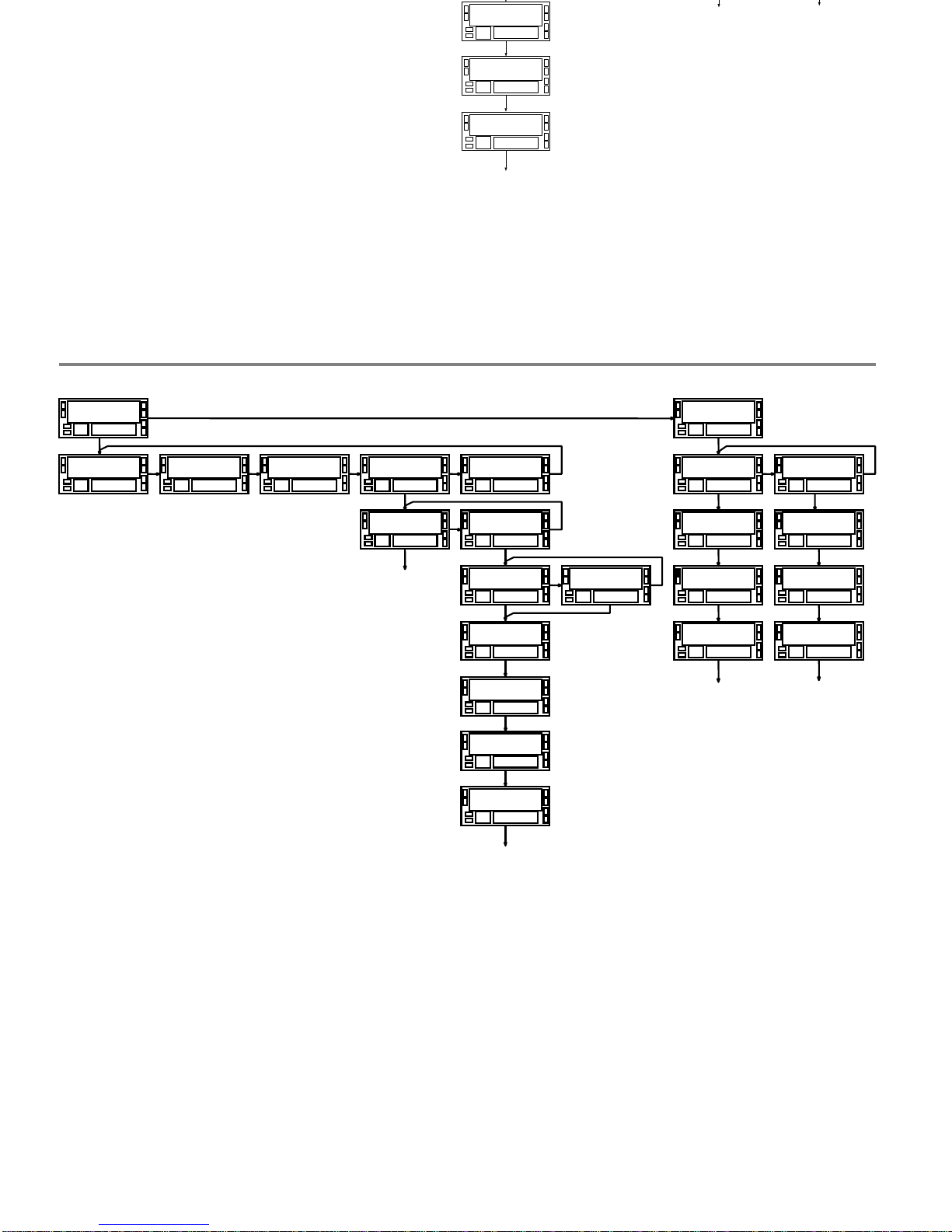
28
28
4.2. Diagram for modules Input and Display
M o d E1 1 E d G E1 2 F I L t1 3
C n F I n P1 0
r A t E1 4
r A t E1 4
n o
r A t E1 4
Y E S
M o d E1 4
d i r E C
M o d E1 4
i n V E r
F r E C1 4
8 8 8 8 8 8
F r E C1 4
8 8 8 8.8 8
PRO
PRO
b t c H 1 5
C n F d S P2 0
C o u n t2 1
d E C P2 1
0 0 0 0 0.0
F A C t2 1
0 9 9 9.9
PRO
o F F S2 1
0 0 0 0 0.0
r A t E 2 2
L i M i t2 2
9 9
M E A n2 2
9 9.9
P P r2 2
9 9 9 9
PRO
d i S P1 4
8 8 8 8 8 8
d i S P1 4
8 8 8 8.8 8
4.2. Diagram for modules Input and Display
M o d E
1 1
E d G E
1 2
F I L t
1 3
C n F I n P
1 0
r A t E
1 4
r A t E
1 4
n o
r A t E
1 4
Y E S
M o d E
1 4
d i r E C
M o d E
1 4
i n V E r
F r E C
1 4
8 8 8 8 8 8
F r E C
1 4
8 8 8 8.8 8
PRO
PRO
b t c H
1 5
C n F d S P
2 0
C o u n t
2 1
d E C P
2 1
0 0 0 0 0.0
F A C t
2 1
0 9 9 9.9
PRO
o F F S
2 1
0 0 0 0 0.0
r A t E
2 2
L i M i t
2 2
9 9
M E A n
2 2
9 9.9
P P r
2 2
9 9 9 9
PRO
d i S P
1 4
8 8 8 8 8 8
d i S P
1 4
8 8 8 8.8 8
Page 29
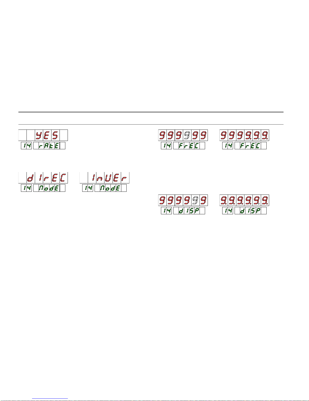
29
29
no
Disable tachometer
YES Enable tachometer
DIRECT SCALE. The relation frequency -
display is directly
proportional; to bigger frequency, bigger display
and to less
frequency less display. This it will be the desirable option in
the majority of the applications.
I NVERSE SCALE. The relation frequency -
display is
inversely proportional; to bigger frequency less display and
vice versa. A typical application
of this option is explained in
the following page.
FREQUENCY OF ENTRY.
To effects of scaling, the
frequency of entry can be any value inside the range of
display (the real limits of frequency are g
iven in the table at
the end of this document).
The decimal point can be placed in the digit 0, the 1 ó 2.
WISHED DISPLAY.
The value to programming in this step
is the value of display corre
sponding to the frequency
programmed in the previous step. The decimal point can
place in any of the digits of the display and is independent
from the decimal point of the totalizer, which is
programmed in the menu 21, module of display ( see pag.
29).
4.3. Input configuration
4.3.1. Tachometer selectio
n and scaling
no
Disable tachometer
YES Enable tachomete
r
DIRECT SCALE. The relation frequency -
display is directly
proportional; to bigger frequency, bigger display and to less
frequency less display. This it will be the desirable option in
the
majority of the applications.
I NVERSE SCALE. The relation frequency -
display is
inversely proportional; to bigger frequency less display and
vice versa. A typical application of this option is explained in
the following page.
FREQUENCY OF ENTRY.
To effects of scaling, the
frequency of entry can be any value inside the range of
display (the real limits of frequency are given in the table at
the end of this document).
The decimal point can be placed in the digi
t 0, the 1 ó 2.
WISHED DISPLAY.
The value to programming in this step
is the value of display corresponding to the frequency
programmed in the previous step. The decimal point can
place in a
ny of the digits of the display and is independent
from the decimal point of the totalizer, which is
programmed in the menu 21, module of display ( see pag.
29).
4.3. Input configuration
4.3.1. Tachometer selection and scaling
Page 30

able of indicating speed, flow or time by
means of the introduction of only two parameters:
Frequency of entry and Value of display
EXAMPLE
Loafs of bread are introduced in an continuous cooking
oven by means of a conveyor belt. The average necessary
tim
e of stay of every piece in the oven is of 15min and 30s.
The conveyor belt moves for a wheel of 20cms of diameter
that provides 6 impulses for return. When the conveyor belt
moves to the speed of 15min30s, the wheel turns to
300rpm.
The enunciated example
allows to expose diverse utilities of
the tachometer.
The speed of rotation of the wheel is of 300 revolutions in
minute, which is equivalent to 5 revolutions per second.
If in a second the wheel carries out 5 turns and every turn
provides 6 impulses, we
have a whole of 30 impulses per
second. The frequency of entry is at the time 30Hz.
SPEED OF THE CONVEYOR BELT (m/s)
To the specified frequency, the speed of the tape is
Rpm
diameter = 300
20 = 18849.6 cm/min that is
equivalent, in m/s, to 3
.142m/s.
PARAMETERS TO PROGRAMMING:
MODE RATE:
DIRECT
FREQUENCY OF ENTRY: 30
VALUE OF WISHED DISPLAY:
03142
DECIMAL POINT:
03.142
(m/s)
It is needed to visualize the time that takes every loaf to
pass for the interior of the oven knowing that to the
calculated frequency (30Hz), the time of cooking is 15 min.
30 s. When it increase the s
peed (and the frequency), it will
diminish the time of cooking, therefore we will have to
programme the tachometer in inverse way.
PARAMETERS TO PROGRAMMING:
MODE RATE:
INVERSE
FREQUENCY OF ENTRY: 30
VALUE OF WISHED DISPLAY:
00155
DECIMAL POINT:
0015.5
(min)
The programming of a value of display corresponding to a
time has to be done in decimal notation. This way, for a
time of cooking of 15min and 30s a value has been
programmed of display of 15.5 (15 minutes and a half).
DAILY PRODUCTION (loafs/day)
Ther
e has been verified of trustworthy way that, in the
conditions of the terms of reference, the loafs go out of the
oven to an average of 10 per minute and the oven works 24
daily hours. The production of loafs is wanted to indicate for
day.
Ten loafs per mi
nute are 10x60=600 loafs per hour.
To the frequency of 30Hz, we have a daily production of
600x24=14400 loafs/day
PARAMETERS TO PROGRAMMING:
MODE RATE:
DIRECT
FREQUENCY OF ENTRY: 30
VALUE OF WISHED DISPLAY:
14400
DECIMAL POINT:
NOT
The tachometer is able of indicating speed, flow or time by
means of the introduction of only two parameters:
Frequency of entry and Value of d
isplay
EXAMPLE
Loafs of bread are introduced in an continuous cooking
oven by means of a conveyor belt. The average necessary
time of stay of every piece in the oven is of 15min and 30s.
The conveyor belt moves for a wheel of 20cms of diameter
that provid
es 6 impulses for return. When the conveyor belt
moves to the speed of 15min30s, the wheel turns to
300rpm.
The enunciated example allows to expose diverse utilities of
the tachometer.
The speed of rotation of the wheel is of 300 revolutions in
minute, whi
ch is equivalent to 5 revolutions per second.
If in a second the wheel carries out 5 turns and every turn
provides 6 impulses, we have a whole of 30 impulses per
second. The frequency of entry is at the time 30Hz.
SPEED OF THE CONVEYOR BELT (m/s)
To the s
pecified frequency, the speed of the tape is
Rpm
diameter = 300
20 = 18849.6 cm/min that is
equivalent, in m/s, to 3.142m/s.
PARAMETERS TO PROGRAMMING:
MODE RATE:
DIRECT
FREQUENCY OF ENTRY: 30
VALUE OF WISHED DISPLAY:
03142
DECIMAL POINT: 03.142
(m/s)
TIME OF COOKING (min)
It is needed to visualize the time that takes every loaf to
pass for the
interior of the oven knowing that to the
calculated frequency (30Hz), the time of cooking is 15 min.
30 s. When it increase the speed (and the frequency), it will
diminish the time of cooking, therefore we will have to
programme the tachometer in inverse
way.
PARAMETERS TO PROGRAMMING:
MODE RATE:
INVERSE
FREQUENCY OF ENTRY: 30
VALUE OF WISHED DISPLAY:
00155
DECIMAL POINT:
0015.5
(min)
The programming of a value of display corresponding to a
time has to be done in decimal notation. This way, for a
time of c
ooking of 15min and 30s a value has been
programmed of display of 15.5 (15 minutes and a half).
DAILY PRODUCTION (loafs/day)
There has been verified of trustworthy way that, in the
conditions of the terms of reference, the loafs go out of the
oven to an a
verage of 10 per minute and the oven works 24
daily hours. The production of loafs is wanted to indicate for
day.
Ten loafs per minute are 10x60=600 loafs per hour.
To the frequency of 30Hz, we have a daily production of
600x24=14400 loafs/day
PARAMETERS T
O PROGRAMMING:
MODE RATE:
DIRECT
FREQUENCY OF ENTRY: 30
VALUE OF WISHED DISPLAY:
14400
DECIMAL POINT:
NOT
30
30
4.3.2. Examples
4.3.2. Examples
Page 31
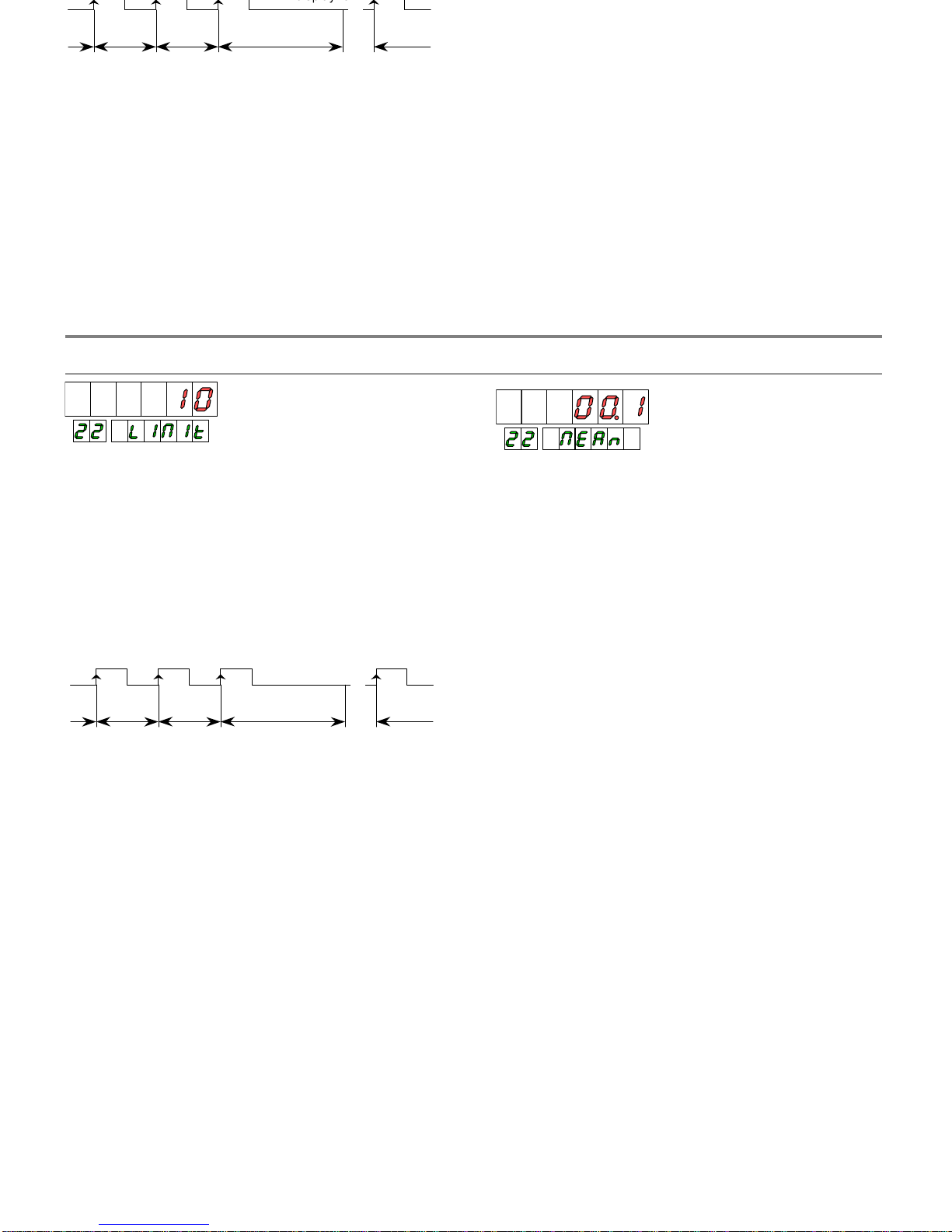
TI ME LIMI T.
The time limit, programmable between 1
and 99s it is applied to limit the time of wait in order that an
impulse takes place in the entry before this one considers
void.
Whenever an impulse
is detected in the entry, an internal
counter puts to zero. Every impulse restarts the counter so
that, while impulses take place this one never comes to the
value programmed as limit. When they stop the impulses
and the counter completes the time limit,
puts to zero the
display and re-starts the measurement.
0..............
0..............
0.................... t límite
0.............
......
display=0
A reduction of this time will mean that the display puts to
zero more rapidly when the system is stopped.
Nevertheless, this reduction also limit the lowest frequencies
(
for example: with a time limit of 10s, it would be
impossible to see low frequencies to 0.1Hz and with a time
of 1s, low frequencies to 1Hz).
The instrument can present in display all the readings at a
rate of 100 pro second (the display refreshes himself every
10ms) or an average of the readings realized during a
programmable time: the AVERAGE TIME
.
The average time is programmable from 0 to 99.9 seconds.
If a value is programmed "0" average is not carried out.
Of factory, this parameter comes programmed to 0.1s.
When troublesome variations should be observed in display
due to the fact th
at the signal is unstable or irregular, an
increase of the time can help to stabilize the display.
The average time can be calculated for a number of
readings determined knowing the frequency of the signal.
( Example: With the programming factory (0.1s),
of a signal
of lower frequency than 10Hz only will manage to take a
reading, with which there is no average. Of a signal of
100Hz approximately 10 readings would take in 0.1s and of
a signal of 1000Hz there would appear in display the
average of approximat
ely 100 readings).
TI ME LIMI T.
The time limit, programmable between 1
and 99s it is applied to limit the time of wait in order that an
impulse takes place in the e
ntry before this one considers
void.
Whenever an impulse is detected in the entry, an internal
counter puts to zero. Every impulse restarts the counter so
that, while impulses take place this one never comes to the
value programmed as limit. When they stop
the impulses
and the counter completes the time limit, puts to zero the
display and re-starts the measurement.
0..............
0..............
0.................... t límite
0.............
......
display=0
A reduction of this time will mean that the display puts to
zero more rapidly when the system is stopped.
Neverthe
less, this reduction also limit the lowest frequencies
(for example: with a time limit of 10s, it would be
impossible to see low frequencies to 0.1Hz and with a time
of 1s, low frequencies to 1Hz).
The instrument can present in display all the readings at a
rate of 100 pro second (the display refreshes himself every
10ms) or an average of
the readings realized during a
programmable time: the
AVERAGE TIME
.
The average time is programmable from 0 to 99.9 seconds.
If a value is programmed "0" average is not carried out.
Of factory, this parameter comes programmed to 0.1s.
When troublesome var
iations should be observed in display
due to the fact that the signal is unstable or irregular, an
increase of the time can help to stabilize the display.
The average time can be calculated for a number of
readings determined knowing the frequency of the
signal.
( Example: With the programming factory (0.1s), of a signal
of lower frequency than 10Hz only will manage to take a
reading, with which there is no average. Of a signal of
100Hz approximately 10 readings would take in 0.1s and of
a signal of 1000Hz
there would appear in display the
average of approximately 100 readings).
31
31
4.4.
Display configuration
4.4.1. Special functions for frequency measurement
4.4. Display configuration
4
.4.1. Special functions for frequency measurement
Page 32
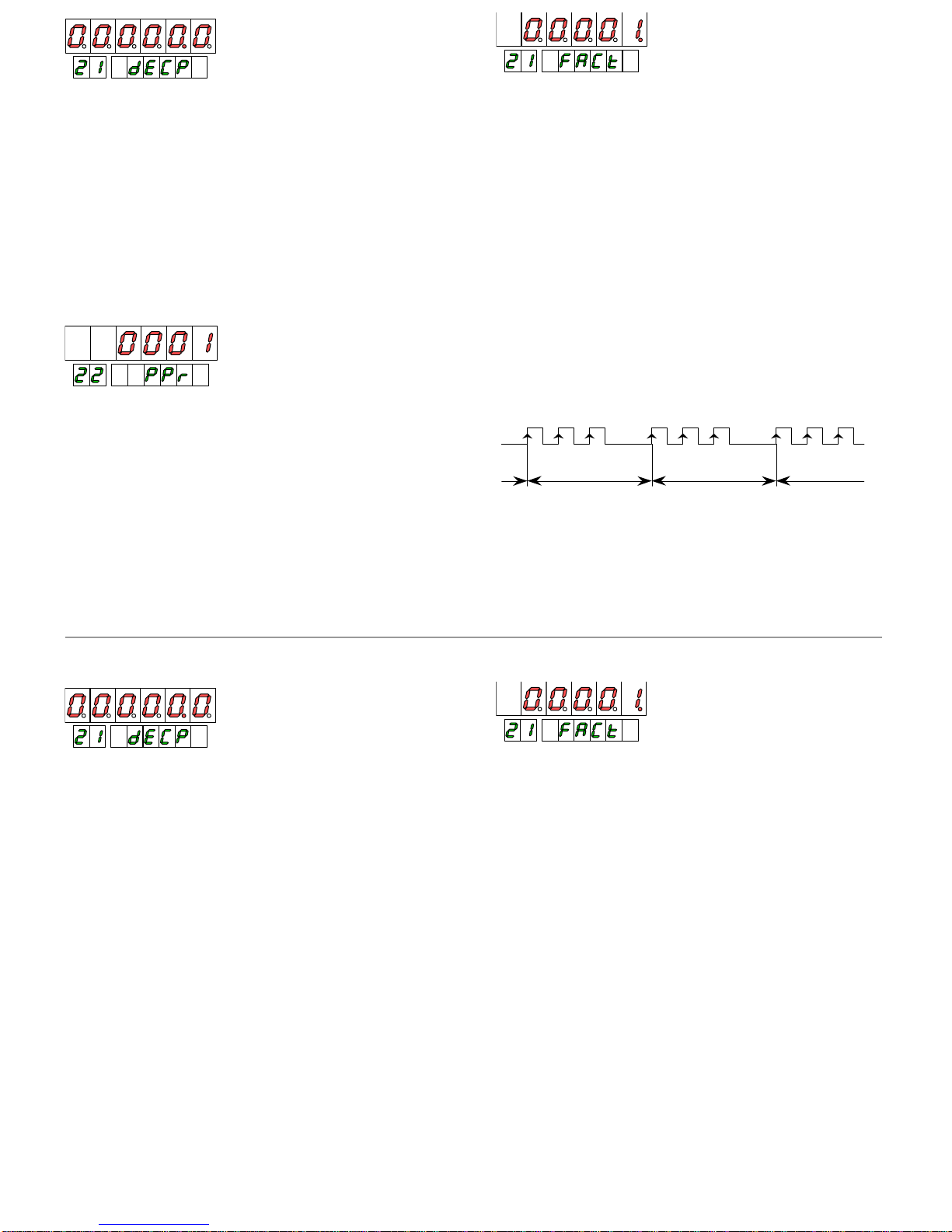
IMPULSES PER TURN.
The reading of the frequency of
entry is realized by the system of counting the time that is
used to complete a period of the signal.
The period is taken between the positive edges of two
consecutive impulses, which corresponds
to a programming
of PPr=0001.
If the input signal gives impulses at not regular intervals,
the display will present fluctuations due to the fact that the
periods of signal are not equal.
DECIMAL POINT.
The decimal point
can place in any of
the digits of the main display.
Its position has value, that is to say, the entire part of a
value will be visualized to the left of the decimal point and
the decimal part to the right (to see explanations section
3.4.1.
In pag. 25)
teeth that generates the following sign:
1 cycle
1cycle
........
......
With a signal a
s that of the figure, if a measurement was
taking for every impulse, the reading would be different in
every measurement resulting in a fluctuating display.
To solve this case a value of 3 is programmed in the
paragraph PPr.
MULTIPLIER FACTOR.
The multiplier factor is
programmable between 0.0001 and 9999 with own decimal
point, for which it is possible to obtain any value inside this
range independently of the number of decimal positions of
the display.
IMPULSES PER TURN.
The reading of the frequency of
entry is realized by the system of counting the time that is
used to complete a period of the signal.
The period is taken b
etween the positive edges of two
consecutive impulses, which corresponds to a programming
of PPr=0001.
If the input signal gives impulses at not regular intervals,
the display will present fluctuations due to the fact that the
periods of signal are not eq
ual.
DECIMAL POINT.
The decimal point can place in any of
the digits of the main display.
Its position has value, that is to say, the entire part of a
value will be visualized to the left of the decimal point and
the decim
al part to the right (to see explanations section
3.4.1.
In pag. 25)
For example, we suppose a wheel that has a distribution of
teeth that gen
erates the following sign:
1 cycle
1cycle
........
......
With a signal as that of the figure, if a measurement was
taking for every impulse, the reading would be different in
every measurement resulting in a fluctuating display.
To solve this case a value
of 3 is programmed in the
paragraph PPr.
MULTIPLIER FACTOR.
The multiplier factor is
programmable between 0.0001 and 9999 with own decimal
point, for which it is possible to obtain any value inside this
range independently
of the number of decimal positions of
the display.
32
32
4.4.2. Display options for totalizer
4.4.2. Display options for totalizer
Page 33

When the configuration is of 3 channels, the programming
of the function 'rAtE' , is referred to only one channel,
channel A, since the measurement of frequency will be
effected only in the entry A.
The par
ameters of display relative to the frequency
measurement (time limit, average time and impulses by
cycle will be applied only to this input)
On the other hand, the parameters relative to the
configuration of the counter (decimal point, offset and
factor multiplier) double
since, in configuration of 3
channels, the channel B is used as counter of impulses with
totalizer and the channel A has a totalizer associated with
the speed measurement, both are independently scaled
except the decimal point that will be the same for th
e
variables total-A, Process-b and total-b.
When the configu
ration is of 3 channels, the programming
of the function 'rAtE' , is referred to only one channel,
channel A, since the measurement of frequency will be
effected only in the entry A.
The parameters of display relative to the frequency
measurement (time li
mit, average time and impulses by
cycle will be applied only to this input)
On the other hand, the parameters relative to the
configuration of the counter (decimal point, offset and
factor multiplier) double since, in configuration of 3
channels, the channel B is used as
counter of impulses with
totalizer and the channel A has a totalizer associated with
the speed measurement, both are independently scaled
except the decimal point that will be the same for the
variables total-A, Process-b and total-b.
33
33
4.5. Notes to diagram (3 channels counter)
4.5. Notes to diagram (3 channels counter)
Page 34

34
34
SECTION
5.1.
Definitions
36
5.2.
Diagram function batch
37
5.3.
Notes to diagram for a 3 channels counter
37
5.4.
Selection and configuration function batch
38
5.5.
Working d
iagrams 39
5. FUNCTION BATCH COUNTER
Index
SECTION
5.1.
Definitions
36
5.2.
Diagram function batch
37
5.3.
Notes to diagram for a 3 channels counter
37
5.4.
Selection and configuration function batch
38
5.5.
Working diagrams 39
5. FUNCTION BATCH COUNTER
Index
Page 35

35
35
It is the number of times that is fulfilled a cycle of
measurement, that is to say, the number of times that
PROCESS variable puts to zero. This variable is
generated
when the function batch is enabled already in automatic
form (BATCH is increased when the process reaches a
prearranged value) as manual (BATCH is increased in every
putting to zero of the process).
Sign
The variable BATCH always is entire and
positive though
there can be associated a counter of negative sign. For
example can count quantity of boxes when removing the
content.
Decimal point
The counter of lots does not have decimal point since the
number of lots only can be an entire number.
B
atch channel C
The variable BATCH-
C is not generated from the variable
PROCESS but an arithmetical operation between the
variables batch of the channels A and B.
The function batch auto, optional, is generated from a
certain level of variable process allowing the count of lots of
fixed quantities as, for example, boxes of 12 b
ottles, etc.
The counter of lots (variable BATCH) is increased in a unit
whenever the partial counter (variable PROCESS) reaches
the quantity for lot programmed. If the partial counter is
affected of a factor multiplier so that the display does not
pass fo
r the exact programmed value, the lot will be
completed by excess, that is to say, when the partial
counter exceeds the programmed quantity, not adding the
above mentioned excess to the following lot.
The partial counter, once reached the level batch, puts
to
zero or to the value of preset.
Mode batch by manual reset
The function batch reset is useful to take an individual
control of every lot, for example, when the quantity of
pieces or of material of every lot is different.
The function batch takes plac
e whenever a reset of the
process is carried out, already it is for keyboard, remotely or
for action of a setpoint. When the operator thinks that the
quantity of a lot is sufficient, remushroom the display I try,
being increased automatically the variable
BATCH in a unit
and being initiated from then the count of the following
cycle.
5.1. Terminology
Variable Batch
It is the number
of times that is fulfilled a cycle of
measurement, that is to say, the number of times that
PROCESS variable puts to zero. This variable is generated
when the function batch is enabled already in automatic
form (BATCH is increased when the process reaches
a
prearranged value) as manual (BATCH is increased in every
putting to zero of the process).
Sign
The variable BATCH always is entire and positive though
there can be associated a counter of negative sign. For
example can count quantity of boxes when rem
oving the
content.
Decimal point
The counter of lots does not have decimal point since the
number of lots only can be an entire number.
Batch channel C
The variable BATCH-
C is not generated from the variable
PROCESS but an arithmetical operation between
the
variables batch of the channels A and B.
Mode automatic batch
The function batch auto, op
tional, is generated from a
certain level of variable process allowing the count of lots of
fixed quantities as, for example, boxes of 12 bottles, etc.
The counter of lots (variable BATCH) is increased in a unit
whenever the partial counter (variable PROCE
SS) reaches
the quantity for lot programmed. If the partial counter is
affected of a factor multiplier so that the display does not
pass for the exact programmed value, the lot will be
completed by excess, that is to say, when the partial
counter exceeds t
he programmed quantity, not adding the
above mentioned excess to the following lot.
The partial counter, once reached the level batch, puts to
zero or to the value of preset.
Mode batch by manual reset
The function batch reset is useful to take an indivi
dual
control of every lot, for example, when the quantity of
pieces or of material of every lot is different.
The function batch takes place whenever a reset of the
process is carried out, already it is for keyboard, remotely or
for action of a setpoint. W
hen the operator thinks that the
quantity of a lot is sufficient, remushroom the display I try,
being increased automatically the variable BATCH in a unit
and being initiated from then the count of the following
cycle.
5.1. Terminology
Page 36
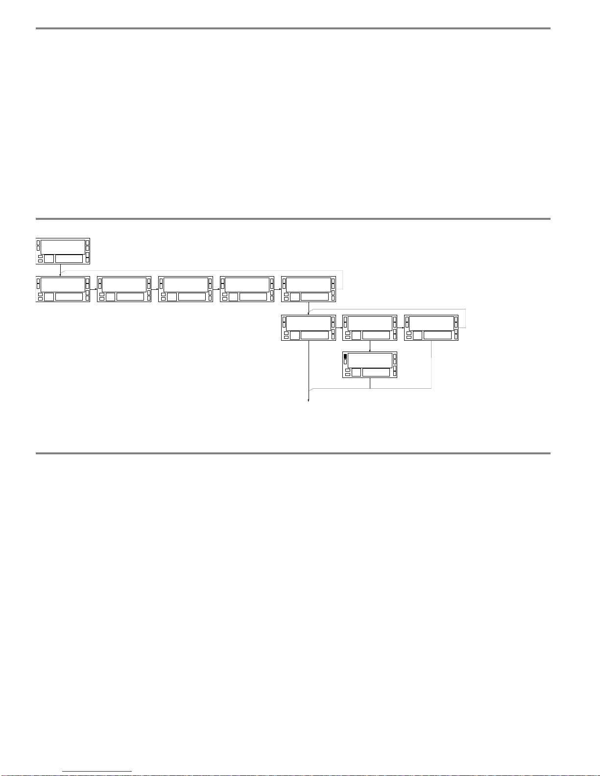
When the counter is of 3 channels, the programming of the
function batch is realized two times (' btCH -A ' and 'btCH-
b') one for every channel being completely independent as
for type of function and level batch, that is
to say, is
possible to to have the counter of lots activated in one only
channel, or the automatic one and other one in way reset,
etc..
When the option has been choosed ba
tch in both channels
A and B, automatically the counter of lots will be activated
batch
-
C that will be the result of an arithmetical operation
between the variables batch-A and batch-B.
This will not exist if only the function is activated in one of
the c
hannels.
When the counter is of 3 channels, the programming of the
function batch is realized two times (' btCH -A ' and 'btCH-
b') one for every channel being completely independent as
for type of function and level batch, that is to say, is
possible to to
have the counter of lots activated in one only
channel, or the automatic one and other one in way reset,
etc..
When the option has been choosed batch in both channels
A and
B, automatically the counter of lots will be activated
batch
-
C that will be the result of an arithmetical operation
between the variables batch-A and batch-B.
This will not exist if only the function is activated in one of
the channels.
36
36
5.3. Notes to diagram ( 3 channels counter)
5.2. Menu batch diagram
M o d E1 1 E d G E1 2 F I L t1 3
C n F I n P1 0
r A t E1 4 b t c H 1 5
b t C H1 5
n o
b t C H
1 5
A u t o
b t C H1 5
r E S E t
L E V E L1 5
9 9 9 9 9.9
PRO
5.3. Notes to diagram ( 3 channels counter)
5.2. Menu batch diagram
M o d E1 1 E d G E1 2 F I L t1 3
C n F I n P1 0
r A t E1 4 b t c H 1 5
b t C H1 5
n o
b t C H
1 5
A u t o
b t C H1 5
r E S E t
L E V E L1 5
9 9 9 9 9.9
PRO
Page 37
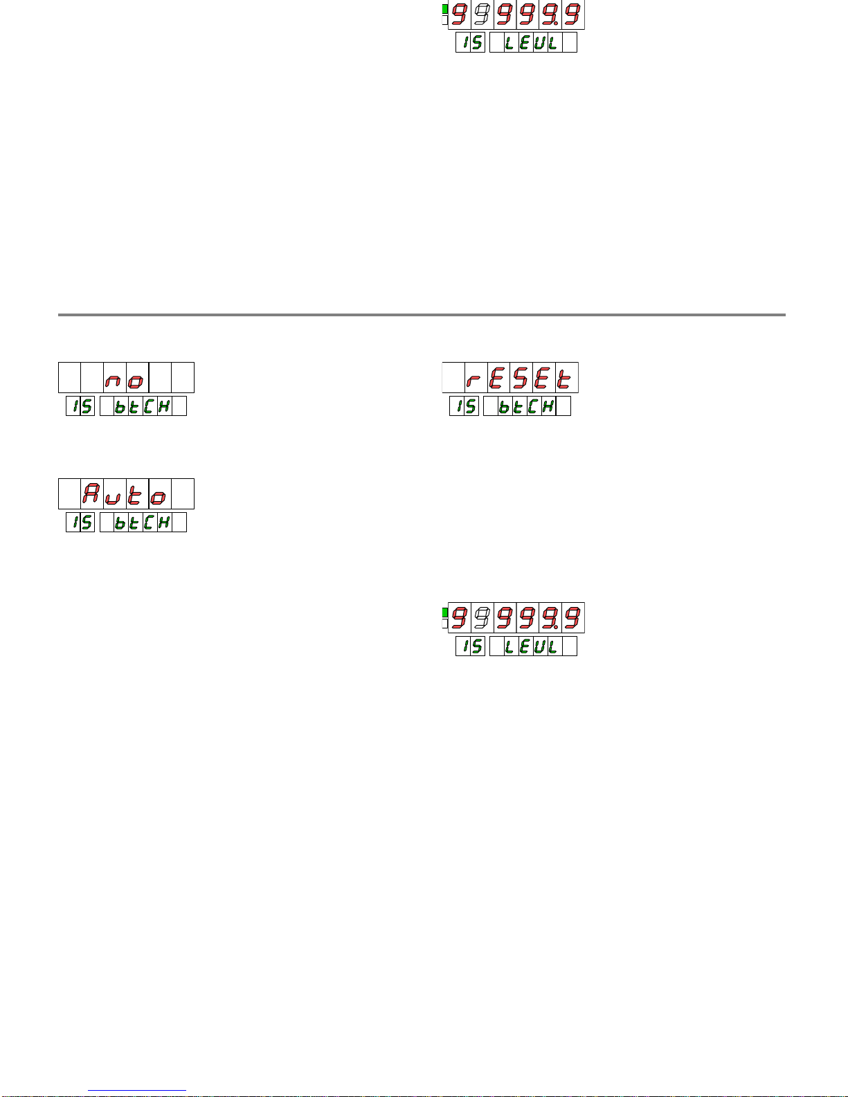
37
37
NO
= disable function
AUTOMATIC BATCH.
The counter of lots (variable BATCH)
is increased in a unit whenever the partial counter (variable
PROCESS) reaches the quantity for lo
t programmed.
If the partial counter is affected of a factor multiplier so that
the display does not pass for the exact programmed value,
the lot will be completed by excess, that is to say, when the
partial counter exceeds the programmed quantity, not
add
ing the above mentioned excess to the following lot.
The partial counter, once reached the level batch, puts to
zero or to the value of preset.
BATCH RESET.
The function batch takes place whenever a
reset of the process is carried out, already it is manual or
for action of a set
point. When the operator thinks that the
quantity of a lot is sufficient, remushroom the display I try,
being increased automatically the variable BATCH in a unit
and being initiated from then the count of the following
cycle.
LEVEL BATCH (Only MODE AUTO
)
Level batch is the value of display in which the process
variableis reset increasing in a unit the counter of lots. This
value is programmed with sign and with the decimal point in
the position of process variable.
5.4. Batch function selection and configuration
SELECTION FUNCTION BATCH
NO
= disable function
AUTO
MATIC BATCH.
The counter of lots (variable BATCH)
is increased in a unit whenever the partial counter (variable
PROCESS) reaches the quantity for lot programmed.
If the partial counter is affected of a factor multiplier so that
the display does not pass fo
r the exact programmed value,
the lot will be completed by excess, that is to say, when the
partial counter exceeds the programmed quantity, not
adding the above mentioned excess to the following lot.
The partial counter, once reached the level batch, puts
to
zero or to the value of preset.
BATCH RESET.
The function batch takes place whenever a
reset of the process is carried out, already it is manual or
for action of a setpoint. When the operator thinks that the
quantity of a lot is sufficient, remushroom the display I try,
bein
g increased automatically the variable BATCH in a unit
and being initiated from then the count of the following
cycle.
LEVEL BATCH (Only MODE AUTO)
Level batch is the value of display in which the process
variableis reset in
creasing in a unit the counter of lots. This
value is programmed with sign and with the decimal point in
the position of process variable.
5.4. Batch function selection and configuration
Page 38

38
38
The level 'batch' is the value that is programmed as quantity
of the lot.
The level 'offset' is the value in which a cycle of count
begins the partial counter. A level offset different of
zero
can be useful, for example, in applications where boxes of
pieces are wished be removed beginning the discount from
a level of offset determined.
To illustrative effects, in the following graphs a level has
been included of offset differently of zero
that, since it can
be observed, it does not affect the totalizer.
MODE UP.
BATCH > OFFSET
process
batch
total
2
1
73849510611
2
2
12
556
6
4
4
3134145
15
332
0
2
batch=7
offset=2
MODE DOWN.
BATCH < OFFSET
process
batch
total
7
1
261504-13-2
7
2
-3
443
3
5
5
6-45-54
-6
667
0
7
offset=7
batch=2
when an equal number of pieces is obtained to the
programmed level, with independence of the previous
evolutions of the counter.
Hereby it is pos
sible to add and remove material with the
safety of which only when there is reached the level of
material wished by lot, will reset the partial counter and that
of lots will be increased.
MODE UP/DOWN. BATCH > OFFSET
process
batch
total
03142536472
2
8
2
1
514
4
4
17061
7
332
0
2
batch=5
offset=2
MODE U
P/DOWN. BATCH < OFFSET
process
batch
total
706-15-24-33-45
2
-5
5
1
263
3
3
6-47-36
-4
445
0
5
offset=5
batch=2
5.4. Working diagrams
The level 'batch' is the value that is programmed as quantity
of the lot.
The level 'offse
t' is the value in which a cycle of count
begins the partial counter. A level offset different of zero
can be useful, for example, in applications where boxes of
pieces are wished be removed beginning the discount from
a level of offset determined.
To illu
strative effects, in the following graphs a level has
been included of offset differently of zero that, since it can
be observed, it does not affect the totalizer.
MODE UP.
BATCH > OFFSET
process
batch
total
2
1
73849510611
2
2
12
556
6
4
4
3134145
15
332
0
2
batch=7
offset=2
MODE DOWN.
BATCH < OFFSET
process
batch
total
7
1
261504-13-2
7
2
-3
443
3
5
5
6-45-54
-6
667
0
7
offset=7
batch=2
In bidirectional way, the function batch will be realized
when an equal number of pieces is obtained to th
e
programmed level, with independence of the previous
evolutions of the counter.
Hereby it is possible to add and remove material with the
safety of which only when there is reached the level of
material wished by lot, will reset the partial counter and t
hat
of lots will be increased.
MODE UP/DOWN. BATCH > OFFSET
process
batch
total
03142536472
2
8
2
1
514
4
4
17061
7
332
0
2
batch=5
offset=2
MODE UP/DOWN. BATCH < OFFSET
process
batch
total
706-15-24-33-45
2
-5
5
1
263
3
3
6-47-36
-4
445
0
5
offset=5
batch=2
5.4. Working diagrams
Page 39

39
39
SECTION
Pág.
6.1.
Keyboard Functions
41-42
6.2.
Logical functions on rear connector
6.2.1. Wiring
43
6.2.2. Table of functions
44-45
6.2.3. Programming functions
46
6.3.
Programming and keyboard functions lockout
47
6. FUNCTIONS BY KEYBOARD AND REAR CONNECTOR.
LOCKOUT
Index
SECTION
Pág.
6.1.
Keyboard Functions
41-42
6.2.
Logical functions on rear connector
6.2.1. Wiring
43
6.2.2. Table of functions
44-45
6.2.3. Programming functions
46
6.3.
Programming and keyboard functions lockout
47
6. FUNCTIONS BY KEYBOARD AND REAR CONNECTOR.
LOCKOUT
Index
Page 40

40
40
OFFSET KEY
Takes the value of the variable shown on upper display like
OFFSET value for this variable.
OFFSET is the beginning counter value after to make a
reset.
By default, the beginning counter value is zero
whether for UP or DOWN. Only the Process-
A and
Process-B can make use of OFFSET value.
In a reset, the totalizer doesnt increase with the offset
value. The totalizer accumulates the input pulses (multiplied
by a factor) independently what is the action on process
displa
y. It is not affected by the quantities added to the
main display not generated by the input pulses , that is to
say, it has been added by a reset-to-
preset or using
load function (manual setting of display value).
Reset of the OFFSET
Simultaneously
use of RESET and OFFSET key resets the
OFFSET value.
To erase
OFFSET
value from process A and/or process B
variables, the instrument should be showing the value
corresponding to this variable on main display but,
NOT I N THE VI SUAL ROUTI NE.
Follow
this method:
4.
If the instrument was in the VISUAL routine,
wait until the variable annunciator disappears
(
have to be numerical value for both
displays.)
5.
Press RESET and holding it, press OFFSET .
6.
First release OFFSET and then RESET
The TARE
LED switches off once finished the operation.
LIMIT KEY
Shows cyclicly, at every press, the setpoint values.
If the setpoint is related to a PROCESS variable or BATCH,
it s value appears on main display while on the auxiliary is
shown which setpoint number is used.
If the setpoin
t is related to a TOTAL, it s value will be shown
on auxiliary display and on the main display which setpoint
number is used.
After 5s without using a key, the instrument comes back
automatically to the run mode.
RESET KEY
Reset to zero (or to a preset va
lue) the selected variable
during VISUAL routine (see VISUAL KEY ).
During normal working, that is to say, out of this routine,
the reset has no effect.
The reset is momentary action, allowing to the counter
follows its functions nevertheless the key is
hold down.
ENTER KEY
A momentary press allows to access to programming mode.
Hold 3 seconds accesses to keyboard functions and program
lock-out.
6.1. K
eyboard Functions
f the variable shown on upper display like
OFFSET is the beginning counter value after to make a
reset.
By default, the beginning counter value is zero
whether for UP or DOWN. Only the Process-
A and
Process-B can make use
of OFFSET value.
In a reset, the totalizer doesnt increase with the offset
value. The totalizer accumulates the input pulses (multiplied
by a factor) independently what is the action on process
display. It is not affected by the quantities added to the
m
ain display not generated by the input pulses , that is to
say, it has been added by a reset-to-
preset or using
load function (manual setting of display value).
Reset of the OFFSET
Simultaneously use of RESET and OFFSET key resets the
OFFSET val
ue.
To erase
OFFSET
value from process A and/or process B
variables, the instrument should be showing the value
corresponding to this variable on main display but,
NOT I N THE VI SUAL ROUTI NE.
Follow this method:
1.
If the instrument was in the VISUAL ro
utine,
wait until the variable annunciator disappears
(
have to be numerical value for both
displays.)
2.
Press RESET and holding it, press OFFSET .
3.
First release OFFSET and then RESET
The TARE LED switches off once finished the operation.
Shows cyclicly, at every press, the setpoint values.
If the setpoint is related to a PROCESS variable or BATCH,
it s value appears on main display w
hile on the auxiliary is
shown which setpoint number is used.
If the setpoint is related to a TOTAL, it s value will be shown
on auxiliary display and on the main display which setpoint
number is used.
After 5s without using a key, the instrument comes bac
k
automatically to the run mode.
RESET KEY
Reset to zero (or to a preset value) the selected variable
during VISUAL routine (see VISUAL KEY ).
During normal working, that is to say, out of this routine,
the reset has no effect.
The reset is momentary a
ction, allowing to the counter
follows its functions nevertheless the key is hold down.
ENTER KEY
A momentary press allows to access to programming mode.
Hold 3 seconds accesses to keyboard functions and program
lock-out.
6.1. Keyboard Functions
Page 41

41
41
VISUAL KEY
One press shows on secondary displays the corresponding
indication of the variable present on main display.
After 5s disappears the indication and the meter goes out from
visualization mode.
If before to finish the 5 seconds, press
the VISUAL key, will be
visualized the next variable if it exist.
Only one press on VISUAL key shows only the variable present on
display, doesn t change it.
On visualization cycle will only appear the active variables
,
that is to say, if the batch functi
on is not active it does not
appears or if the counter is only one channel, channels B and C do
not appear.
VISUAL + ENTER KEYS
If during the indication of main variable indication press ENTER
key, the VISUAL routine will show the total values on second
ary
display.
(Pressing ENTER , the actual variable on main display will remain
like default variable).
VISUALIZATION VARIABLES ON AUXILIARY DISPLAY
To show on auxiliary display the variables process or batch instead
total, is necessary to activate the lo
gical function Nr 27 (see page
45, blank auxiliary display), that blanks auxiliary display when is
used like totalizer display.
This function is useful when needed to have simultaneous
indication of process value and number of batch, or process value
of ea
ch channel, and always is possible to see the total getting the
visual routine.
With Nr 27 logical function activated, push VISUAL key to enter
into routine of variabless visualization. Push once again to change
the variable on main display ( only will sh
ow the process and batch
variables activated according programming)
Next, push ENTER to select the auxiliary display variables.
Pushing repeatedly the VISUAL key, will appear all the activated
variables including process, batch and totals.
If a process or batch value has been selected, this will remain
fixed on the auxiliary display as long as the function Nr27 is
active. ( when deactivated, pass to show the total A). If a total
value is select
ed the display will blank and only can show the
total getting the VISUAL routine.
NOTES:
-
The LOAD function (programming of initial value of any
variable), doesnt work on auxiliary display with process or
batch variables. To load a specific value for this
variables should
be done from the main display, automatically will be reflected
on auxiliary display, after that is necessary to select the variable
of main display since will remain the loaded with a new value.
-A request through serial channel, will sen
d the variable on this
auxiliary display , be process, batch or total.
Function LOAD
The LOAD function allows to introduce by key an initial
counting value into anyone display. This value is loaded as an
actual counting value and it s not stored for futu
re uses.
During the VISUAL routine, when the variable we would like to
modify is on display, press ENTER key during 3 seconds, at
the end of this 3 seconds, the first left digit or the sign led go to
blink.
The programming of the value is done in an
standard way and
at the end, a press on ENTER key allows to exit from this
programming step, following the VISUAL routine to the next
step.
The programmed value is loaded into the selected variable
when press ENTER key, beginning the counting from this
point.
One press shows on secondary displays the corresponding
visualization mode.
If before to finish the 5 seconds, press the VISUAL key, will be
visualized the next variable if it exist.
Only one press on VISUAL key shows only the variable present on
display, doesn t change it.
On visualization cycle will only appear the active variables
,
that is to say, if the batch function is not active it does not
appears or if the counter is only one channel, channels B and C do
not appear.
VISUAL + ENTER KEYS
If during the indication of main variable indication press ENTER
key, the VISUAL routine will show the total values on secondary
display.
(Pressing ENTER , the actual variable on main display will remain
like default variable).
VISUALIZATION VARIABLES ON AUXILIARY DISPLAY
To show on auxiliary display the variables p
rocess or batch instead
total, is necessary to activate the logical function Nr 27 (see page
45, blank auxiliary display), that blanks auxiliary display when is
used like totalizer display.
This function is useful when needed to have simultaneous
indicatio
n of process value and number of batch, or process value
of each channel, and always is possible to see the total getting the
visual routine.
With Nr 27 logical function activated, push VISUAL key to enter
into routine of variabless visualization. Push on
ce again to change
the variable on main display ( only will show the process and batch
variables activated according programming)
shing repeatedly the VISUAL key, will appear all the activated
If a process or batch value has been selected, this will remain
fixed on the auxiliary display as long as the function Nr27 is
active. ( when deac
tivated, pass to show the total A). If a total
value is selected the display will blank and only can show the
total getting the VISUAL routine.
NOTES:
-
The LOAD function (programming of initial value of any
variable), doesnt work on auxiliary display with
process or
batch variables. To load a specific value for this variables should
be done from the main display, automatically will be reflected
on auxiliary display, after that is necessary to select the variable
of main display since will remain the loaded
with a new value.
-
A request through serial channel, will send the variable on this
auxiliary display , be process, batch or total.
Function LOAD
The LOAD function allows to introduce by key an initial
counting value into anyone display. This value is l
oaded as an
actual counting value and it s not stored for future uses.
During the VISUAL routine, when the variable we would like to
modify is on display, press ENTER key during 3 seconds, at
the end of this 3 seconds, the first left digit or the sig
n led go to
blink.
The programming of the value is done in an standard way and
at the end, a press on ENTER key allows to exit from this
programming step, following the VISUAL routine to the next
step.
The programmed value is loaded into the selected var
iable
when press ENTER key, beginning the counting from this
point.
Page 42
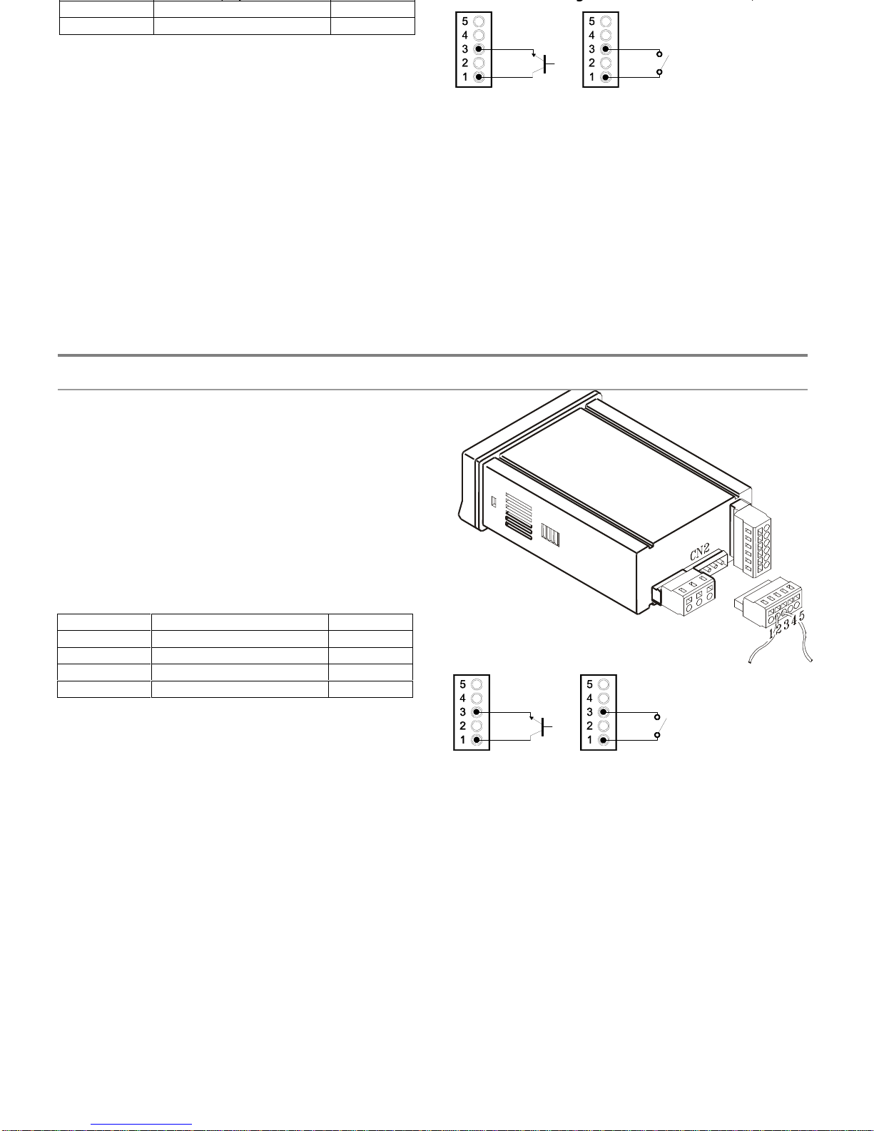
42
42
6.2.1.
Wiring
The rear connector CN2 provides 4 user programmable
opto
-coupled inputs that can be operated from external
contacts or logic levels supplied by an electronic system.
Four different functions may be then added to the functions
available from the front-panel keys. Each function is
associated to one of the CN2 connector pins (PIN 1, PIN 2,
PIN 4 and PIN 5) and is activated by applying a falling edge
or a low level pulse to the corresponding pin with respect to
common (PIN 3).
Each pin can be assigned to one of the 26 functions listed
on the following pages.
CN2 : DEFAULT CONFIGURAT
ION:
INPUT PIN FUNCTION
Nr FUNC.
INPUT 1
Visualization variables
1
INPUT 2
Hold of display
2
INPUT 4
Reset counter
6
INPUT 5
Reset totalizer
7
PIN 3 = COMMON
The external electronics (fig.43.2) applied to the CN2
connector must be capable of withstanding 40 V and 20 mA
present at all terminals with respect to COMMON. In order
to guarrantee the electromagnetic compatibility, please refer
to the instructions given on page 10.
6.2. Programmable logical functions on rear connector
fig. 43.1
: Connector CN2
fig. 43.2
: Wiring examples.
From left to right, electronic device, closure switch.
6.2.1.
Wiring
The rear connector CN2 provides 4 user programmable
opto
-coupled inputs that can be operated from external
contacts or logic levels supplied by an electronic system.
Four different functions may be then added to the functions
available from the front-panel keys. Each function is
associated to one of the CN2 connector pins (PIN 1, PIN 2,
PIN 4 and PIN 5) and is activated by applying a falling edge
or a low level pulse to the corresponding pin with respect to
common (
PIN 3).
Each pin can be assigned to one of the 26 functions listed
on the following pages.
CN2 : DEFAULT CONFIGURATION:
INPUT PIN
FUNCTION
Nr FUNC.
INPUT 1
Visualization variables
1
INPUT 2
Hold of display
2
INPUT 4
Reset counter
6
INPUT 5
Reset total
izer
7
PIN 3 = COMMON
The external electronics (fig.43.2) applied to the CN2
connector must be capable of withstanding 40 V and 20 mA
present at all terminals with respect to COMMON. In order
to guarrantee the electromagnetic compatibility, please refer
t
o the instructions given on page 10.
fig. 43.1
: Connector CN2
fig. 43.2
: Wiring examples.
From left to right, electronic device, closure switch.
Page 43

43
43
Definition of ACTION column
Pulsation :The function
is active applying a negative edge to the corresponding pin referred to common.
Level : The function will be active as long as the corresponding pin is low referred to common.
Definition
of group 1 and group 2
The functions that mean a reset (
except
RESET TOTAL) or printing one or several variables allow to program which variables
will be affected (see diagram).
There are two groups of variables associated to reset function and two groups more associated to printing.
Nr
FUNCTION
DESCRIPTION
ACTION
0 D
eactivated
None
-
1
VISUAL
Cyclical visualization of process variables, batch and total of every channel
with their corresponding annunciator. It s similar to the function VISUAL
by key except for not use of ENTER key to go to visualize the totals th
at
follow the rest of variables.
Pulsation
2
HOLD1
Hold main and secondary display.
Level
3
HOLD2
Hold the main and secondary display, analog output and the display values
that in this moment could be sent through serial channel.
Level
4
HOLD1 + RESET
1 Reset to the preset value the variables programmed YES on group 1
holding the display value until a new hold1 + reset1 (all internal functions
of the counter will follow working).
Pulsation
5
HOLD2 + RESET1
Reset to the preset value the variables programmed YES on group 1
holding the display value , analog output and RS output hold until a new
hold2 + reset1 (counting and setpoints functions will follow internally
working).
Pulsation
6
RESET1
Reset to the preset value the variables programmed YES on gr
oup 1
Pulsation
7
RESET2
Reset to the preset value the variables programmed YES on group 2
Pulsation
6.2.2. Table of p
rogrammable functions
Pulsation :The function is active applying a negative edge to the corresponding pin referred to common.
Level : The function will be active as l
ong as the corresponding pin is low referred to common.
Definition
of group 1 and group 2
The functions that mean a reset (
except
RESET TOTAL) or printing one or several variables allow to program which variables
will be affected (see diagram).
There are
two groups of variables associated to reset function and two groups more associated to printing.
Nr
FUNCTION
DESCRIPTION
ACTION
0
Deactivated
None
-
1
VISUAL
Cyclical visualization of process variables, batch and total of every channel
with their corresponding annunciator. It s similar to the function VISUAL
by key except for not use of ENTER key to go to visualize the totals that
follow the rest of variables.
Pulsation
2
HOLD1
Hold main and secondary display.
Level
3
HOLD2
Hold the main and sec
ondary display, analog output and the display values
that in this moment could be sent through serial channel.
Level
4
HOLD1 + RESET1
Reset to the preset value the variables programmed YES on group 1
holding the display value until a new hold1 + reset1 (all internal functions
of the counter will follow working).
Pulsation
5
HOLD2 + RESET1
Reset to the preset value the variables programmed YES on group 1
holding the display value , analog output and RS output hold until a new
hold2 + reset1 (counting and setpoints functions will follow internally
working).
Pulsation
6
RESET1
Reset to the preset value the variables programmed YES on group 1
Pulsation
7
RESET2
Reset to the preset value the variables programmed YES on group 2
Pulsation
6.2.2. Table of programmable functions
Page 44

44
44
Nr
FUNCTION
D
ESCRIPTION
ACTION
8
STOP + RESET1
Stop all counters while the function is active, and upon deactivate the
function resets to the preset value the variables programmed YES on
group 1 following counting from this value.
Level
9
STOP + RESET 2
Idem functio
n 8 but resets the variables of group 2.
Level
10
RESET TOTAL
Resets all variables TO ZERO and deactivates all setpoints included LATCH
-
2 except for which on zero condition should be actives.
Pulsation
11
INHIBIT A
Inhibits input A as long as the functio
n is activated.
Level
12
INHIBIT B
Inhibits input B as long as the function is activated
.
Level
13
INHIBIT BATCH A
Inhibits the function BATCH RESET of channel A, that is to say, doesn t
increase the variable BATCH A on a reset of PROCESS value.
Level
14
INHIBIT BATCH B
Inhibits the function BATCH RESET of channel B, that is to say, doesn t
increase the variable BATCH A on a reset of PROCESS value.
Level
15
OFFSET
Takes the value of process A or process B ( if this is showed on main
display) as value
of preset A or preset B)
Pulsation
16
RESET OFFSET
Resets the value of preset A or preset B (if the process A or process B
respectively are on main display )
Pulsation
17
PRINT 1
Print the variables and total programmed YES on group 1
Pulsation
18
P
RINT 2
Print the variables programmed YES on group 2
Pulsation
19
PRINT SET1
Print setpoint 1 and its state
Pulsation
20
PRINT SET2
Print setpoint 2 and its state
Pulsation
21
PRINT SET3
Print setpoint 3 and its state
Pulsation
22
PRINT SET4
Print
setpoint 4 and its state
Pulsation
23
ZERO ANA
Takes the analog output to zero condition (0V or 4mA according type)
Level
24
RESET LATCH
Unlock outputs of setpoint latch-2 and, if the alarm condition disappeared
they are deactivated.
Pulsation
25
HOLD SETPOINTS Inhibits comparison with setpoints while the function is active.
Level
26
FALSE SETPOINTS Allows programming and use of 4 setpoints when there is no output card
plugged in, as long as the function is active.
Level
27
SWITCH OFF AUX.
DISP.
Swi
tch off the auxiliary display
Level
9
STOP + RESET 2
Idem function 8 but resets the variables of group 2.
Level
10
RE
SET TOTAL
Resets all variables TO ZERO and deactivates all setpoints included LATCH
-
2 except for which on zero condition should be actives.
Pulsation
11
INHIBIT A
Inhibits input A as long as the function is activated.
Level
12
INHIBIT B
Inhibits input B
as long as the function is activated
.
Level
13
INHIBIT BATCH A
Inhibits the function BATCH RESET of channel A, that is to say, doesn t
increase the variable BATCH A on a reset of PROCESS value.
Level
14
INHIBIT BATCH B Inhibits the function BATCH RESET
of channel B, that is to say, doesnt
increase the variable BATCH A on a reset of PROCESS value.
Level
15
OFFSET
Takes the value of process A or process B ( if this is showed on main
display) as value of preset A or preset B)
Pulsation
16
RESET OFFSET
R
esets the value of preset A or preset B (if the process A or process B
respectively are on main display )
Pulsation
17
PRINT 1
Print the variables and total programmed YES on group 1
Pulsation
18
PRINT 2
Print the variables programmed YES on grou
p 2
Pulsation
19
PRINT SET1
Print setpoint 1 and its state
Pulsation
20
PRINT SET2
Print setpoint 2 and its state
Pulsation
21
PRINT SET3
Print setpoint 3 and its state
Pulsation
22
PRINT SET4
Print setpoint 4 and its state
Pulsation
23
ZERO ANA
Takes
the analog output to zero condition (0V or 4mA according type)
Level
24
RESET LATCH
Unlock outputs of setpoint latch-2 and, if the alarm condition disappeared
they are deactivated.
Pulsation
25
HOLD
SETPOINTS Inhibits comparison with setpoints while t
he function is active.
Level
26
FALSE SETPOINTS Allows programming and use of 4 setpoints when there is no output card
plugged in, as long as the function is active.
Level
27
SWITCH OFF AUX.
DISP.
Switch off the auxiliary display
Level
Page 45
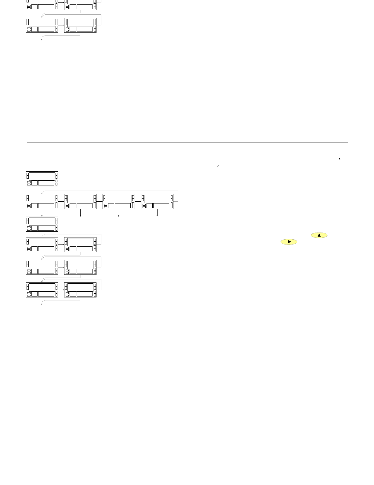
45
45
6.2.3. Programming of logical functions
DIAGRAM
The logical functions are programmed on module
60
LoGInP
. There are 4 menus each one of them corresponds
to an input of connector CN2 :
61 InP-1 : I
nput pin 1
62 InP-2 : Input pin 2
63 InP-4 : Input pin 4
64 InP-5 : Input pin 5
The pin 3 is the common.
On each menu is selected a number from 0 to 26 according
to the desired function.
To change the number, press repeatedly the
key.
To program the next input, press
.
On the left diagram is shown the whole programming
module where can see that after the function number is
possible to select the variable affected by this function.
I n P - 16 1
0 6
L o G I n P6 0
I n P - 26 2
0 0
I n P - 46 3
0 0
I n P - 56 4
0 0
G r o u P 16 1
P r o C6 1
n o
P r o C6 1
Y E S
b t C H6 1
n o
b t C H6 1
Y E S
t o t6 1
n o
t o t6 1
Y E S
PRO
6.2.3. Programming of logical functions
DIAGRAM
The logical functions are programmed on module
60
LoG
InP
. There are 4 menus each one of them corresponds
to an input of connector CN2 :
61 InP-1 : Input pin 1
62 InP-2 : Input pin 2
63 InP-4 : Input pin 4
64 InP-5 : Input pin 5
The pin 3 is the common.
On each menu is selected a number from 0 to 26 accordi
ng
to the desired function.
To change the number, press repeatedly the
key.
To program the next input, press
.
On the left diagram is shown the whole programming
module where can see that after the function number is
possible
to select the variable affected by this function.
I n P - 16 1
0 6
L o G I n P6 0
I n P - 26 2
0 0
I n P - 46 3
0 0
I n P - 56 4
0 0
G r o u P 16 1
P r o C6 1
n o
P r o C6 1
Y E S
b t C H6 1
n o
b t C H6 1
Y E S
t o t6 1
n o
t o t6 1
Y E S
PRO
Page 46

46
46
The instrument is supplied wi
th all software programming
parameters accessible to operator's modifications. After
completing the software configuration, it is recommended to
take the following steps:
1.
Lockout programming parameters to prevent from
accidental or unauthorized modificati
ons.
2.
Lockout keyboard functions to prevent from accidental
or unauthorized modifications.
3.
The access to the lockout routine is allowed by entering
a safety code. At factory this code is set to 0000. We
recommend to change this code and to write it down
and keep safe.
4.
The access to the lockout routine is allowed by entering
a safety code. At factory this code is set to
0000
. We
recommend to change this code and to write it down
and keep safe.
TOTAL LOCKOUT
The access to the programming routines to read data is
allowed even if all parameters are locked out, but
it won t
be possible to enter or modify data
. In this case, when
entering in the pro
gramming mode, the second display
shows the indication
dAtA- instead of
Pro-.
SELECTIVE LOCKS
When only some parameters are locked out, all
configuration data can be read but only non-
protected
parameters can be modified
. In such case, when
entering in
the programming mode, the second display
shows the indication
Pro-.
KEYBOARD FUNCTI ON S LOCKOUT
All keyboard functions in RUN mode except setpoint
visualization values, should be inhibit independently by
software.
6.
3. Programming and keyboard functions lockout
The instrument is supplied with all software programming
parameters accessible to operator's modifications. After
completing the software configuration, it is recommended to
take the following steps:
1.
Lockout programming paramete
rs to prevent from
accidental or unauthorized modifications.
2.
Lockout keyboard functions to prevent from accidental
or unauthorized modifications.
3.
The access to the lockout routine is allowed by entering
a safety code. At factory this code is set to 0000
. We
recommend to change this code and to write it down
and keep safe.
4.
The access to the lockout routine is allowed by entering
a safety code. At factory this code is set to
0000
. We
recommend to change this code and to write it down
and keep safe.
The access to the programming routines to read data is
allowed even if all parameters are locked out, but
it won t
be possible to enter or modify data
. In this case, when
entering in the programming mode, the second display
shows the indication
dAtA- instead of
Pro-.
SELECTIVE LOCKS
When only some parameters are locked out, all
configuration data can be read but only non-
protected
pa
rameters can be modified
. In such case, when
entering in the programming mode, the second display
shows the indication
Pro-.
KEYBOARD FUNCTI ON S LOCKOUT
All keyboard functions in RUN mode except setpoint
visualization values, should be inhibit independ
ently by
software.
6.3. Programming and keyboard functions lockout
Page 47
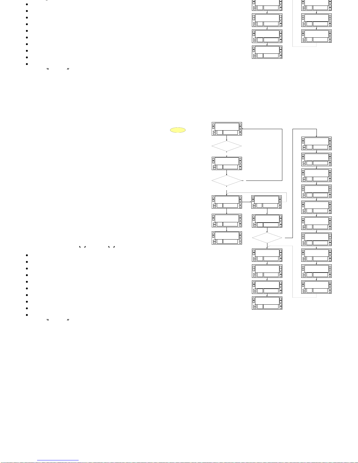
47
47
The diagram shows all phases of the lockout routine which allows to
lockout the programming parameters and to change the safe
ty code.
The access to this routine is accomplished by holding
ENTER
for
approximately 3s until the indication "CodE" appears on the second
display.
The unit is shipped from the factory with a safety code of
"0000".
Once introduced t
his code, you are asked to select whether to change
it or to enter directly in the parameter lockout list.
If you decide to change the default code, after programming the new
one, the instrument returns to the run mode. You will be asked to
enter the new
code before trying to access the lockout routine for the
next time.
If you decide not to change the safety code, the next step ('tot-
LC')
allows to lock everything and return to the run mode (set digit to 1) or
to access the list of parameters which can b
e locked individually (set
tot-LC to 0).
Meaning of menus
( 1 locked, 0 unlocked
) :
tot-LC
: total lock
Set1, Set2, Set3, Set4
: individual lock of setpoints
InPut
: Lock of Input module
dISP
: Lock of Display module
AnAout
: Lock of analog
output option module
rS CoM
: Lock of serial output option
SP VAL
: Lock of direct access of programming setpoints
RESEt
: Inhibit the reset function.
OFFSEt
: Inhibit the offset function and reset of offset
LoAd
: Inhibit the introduction of val
ues of counter by keyboard
during VISUAL routine.
Code=OK ?
yes
C o d E
- - - -
t o t - L C
0
S E t 1
0
S E t 2
0
S E t 3
0
S E t 4
0
I n P U t
0
d S P
0
L o G i n P
0
S P V A L
0
C o d E
- - - -
ENTER 3s ?
yes
8 8 8 8 8 8
8 8
8 8 8 8 8 8
C H A n G E
Y E S
no
S t o r E
tot-LC=0 ?
A n A o u t
0
r S C o M
0
L o A d
0
S t o r E
r E S E t
0
o F F S E t
0
C H A n G E
no
no
The diagram shows all phases of the lockout routine which allows to
programming parameters and to change the safety code.
for
approximately 3s until the indication "CodE" appears on the second
The unit is shipped from the factory with a safety code of
"0000".
Once introduced this code, you are asked to select whether to change
it or to enter directly in the parameter lockout list.
If you decide to change the default code, after programming the new
one, the instrument returns to the
run mode. You will be asked to
enter the new code before trying to access the lockout routine for the
next time.
If you decide not to change the safety code, the next step ('tot-
LC')
allows to lock everything and return to the run mode (set digit to 1) or
to access the list of parameters which can be locked individually (set
tot-LC to 0).
Meaning of menus
( 1 locked, 0 unlocked
) :
tot-LC
: total lock
Set1, Set2, Set3, Set4
: individual lock of setpoints
InPut
: Lock of Input module
dISP
: Loc
k of Display module
AnAout
: Lock of analog output option module
rS CoM
: Lock of serial output option
SP VAL
: Lock of direct access of programming setpoints
RESEt
: Inhibit the reset function.
OFFSEt
: Inhibit the offset function and reset of of
fset
LoAd
: Inhibit the introduction of values of counter by keyboard
during VISUAL routine.
Code=OK ?
yes
C o d E
- - - -
t o t - L C
0
S E t 1
S E t 2
0
S E t 3
0
S E t 4
0
I n P U t
0
d S P
0
L o G i n P
0
S P V A L
0
C o d E
- - - -
ENTER 3s ?
yes
C H A n G E
Y E S
no
S t o r E
tot-LC=0 ?
A n A o u t
0
r S C o M
0
L o A d
0
S t o r E
r E S E t
0
o F F S E t
0
C H A n G E
no
no
Page 48

48
48
SECTION
7.1.
Output Options
50-51
7.2.
Technical characteristics
52-53
7.3.
Dimensions and mounting
54
7.4.
Warranty
55
7.5.
Certificate of conformity
57
7.
SPECIFICATIONS
Index
SECTION
7.1.
Output Options
50-51
7.2.
Technical characteristics
52-53
7.3.
Dimensions and mounting
54
7.4.
Warranty
55
7.5.
Certificate of conformity
57
7.
SPECIFICATIONS
Index
Page 49

49
49
6.1.
OUTPUT OPTION
S
Optionally, model BETA-
M can incorporate one or several
output options for communications or control including :
COMMUNICATION
RS2 Serial RS232C
RS4 Serial RS485
CONT
ROL
ANA Analogue 4-20 mA, 0-10 V
2RE 2 SPDT relays 8 A
4RE 4 SPST relays 0.2 A
4OP 4 open-collector NPN outputs
4OPP 4 open-collector PNP outputs
All options are opto-
isolated with respect to the input signal
and the main supply.
The options are supplied with a specific instructions manual
describing characteristics, installation, connections and
programming. The output cards are easily installed on the
meter's main board by means of plug-
in connectors and
each one activates its own programming module that
provides complete software configuration.
Additional capabilities of the unit with output options :
Control and processing of limit values via ON/OFF logic
outpu
ts (2 relays, 4 relays, 4 NPN outputs or 4 PNP
outputs) or proportional output (4-20 mA or 0-10 V).
Communication, data transmission and remote
programming via serial interface.
For more detailed information on characteristics,
applications, mounting and
programming, please refer to
the specific manual supplied with each option.
6.1.
OUTPUT OPTIONS
Optionally, model BETA-
M can incorporate one or several
output options for communications or control including :
COMMUNICATION
RS2 Serial RS232C
RS4 Serial RS485
CONTROL
ANA Analogue 4-20 mA, 0-10 V
2RE 2 SPDT relays 8 A
4RE 4 SPST relays 0.2 A
4OP 4 open-collector NPN outputs
4OPP 4 open-collector PNP outputs
All options are opto-isolated with respect to
the input signal
and the main supply.
The options are supplied with a specific instructions manual
describing characteristics, installation, connections and
programmin
g. The output cards are easily installed on the
meter's main board by means of plug-
in connectors and
each one activates its own programming module that
provides complete software configuration.
Additional capabilities of the unit with output options :
Co
ntrol and processing of limit values via ON/OFF logic
outputs (2 relays, 4 relays, 4 NPN outputs or 4 PNP
outputs) or proportional output (4-20 mA or 0-10 V).
Communication, data transmission and remote
programming via serial interface.
For more detailed
information on characteristics,
applications, mounting and programming, please refer to
the specific manual supplied with each option.
Page 50
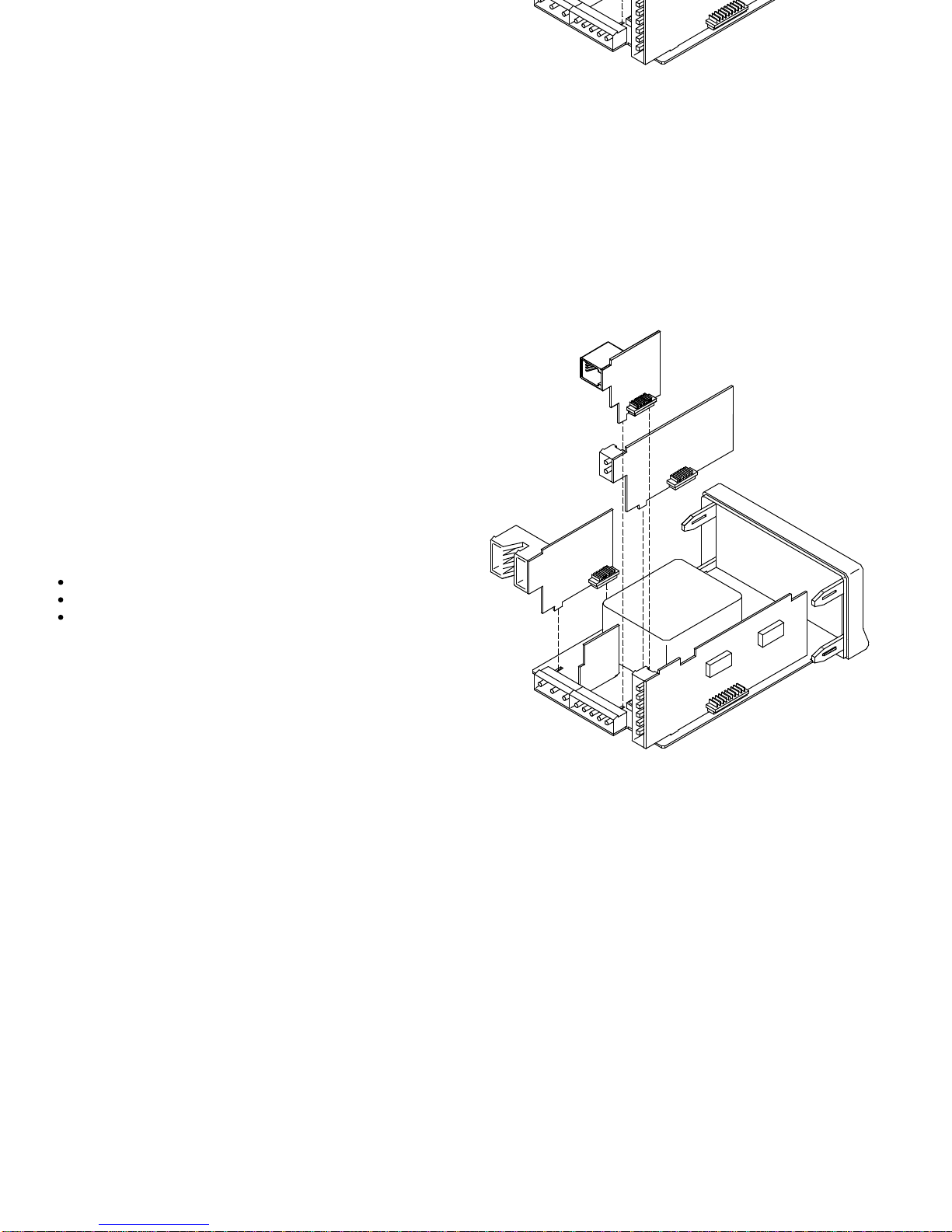
Drawing on the right shows how to plug-
in different output
options.
The options 2RE, 4RE , 4OP and 4OPP are excluding and
only accepts one in
to connector M5.
The options RS2 y RS4 are also excluding and only accepts
one into connector M1
The ANA analog option is plugged in connector M4.
Can be plugged-
in and working simultaneously up to 3
options:
one analog (ref. ANA),
one RS232C (ref. RS
2) or RS485 (ref. RS4).
one 2 relay (ref. 2RE) ó 4 relay (ref. 4RE) or 4 optos
NPN (ref. 4OP) or 4 optos PNP (ref. 4OPP).
in different output
The options 2RE, 4RE , 4OP and 4OPP are excluding and
only accepts one into connector M5.
The options RS2 y RS4 are also exclu
ding and only accepts
one into connector M1
The ANA analog option is plugged in connector M4.
Can be plugged-
in and working simultaneously up to 3
options:
one analog (ref. ANA),
one RS232C (ref. RS2) or RS485 (ref. RS4).
one 2 relay (ref. 2RE) ó 4 rela
y (ref. 4RE) or 4 optos
NPN (ref. 4OP) or 4 optos PNP (ref. 4OPP).
50
50
Page 51
Table of maximum frequencies :
Configuration
No Options
n 4 setpoints
4 setps+analog+rs
Counter
1 input, 1 edge
13
KHz
9,5
KHz
7,5 KHz
1 input, 2 edges
8
KHz
5,5
KHz
4,5
KHz
2 inputs, 1 edge
6
KHz
4,5
KHz
3,5
KHz
2 inputs, 2 edges
4
KHz
3
KHz
2
KHz
Tachometer
1 input, 1 edge
12
KHz
9
KHz
7
KHz
1 input, 2 edges
9
KHz
6
KHz
5
KHz
2 inputs, 1 edge
7
KHz
5
KHz
4
KHz
2 inputs,
2 edges
5
KHz
3
KHz
2
KHz
INPUT SIGNAL
Sensor excitation
..............................
8V/24V DC @ 30mA
Minimum frequency like tachometer
.......................
0.02Hz
.......
20 ±5 Vdc @ 60mA (Max environmental temp. 50ºC)
MAGNETIC PICKUP
Sensitivity
.......................................
Vin (AC) > 120mVeff
NAMUR SENSOR
Rc
..............................................................
1K (included)
Ion
................................................................
< 1mA D
C
Ioff
..................................................................
>3mA DC
TTL/24V DC (ENCODER)
logical levels
.......................
"0" < 2.4V DC, "1" > 2.6V DC
SENSOR TYPE NPN ó PNP
Rc
..............................................................
1K (included)
logical levels
.......................
"0" < 2.4V DC, "1" > 2.6V DC
SWITCH CONTACTS
Vc
..............................................................................
5V
Rc
...........................................................................
3.9K
.Fc
........................................................................
100Hz
Table of maximum frequencies :
Configuration
No
Options
n 4 setpoints
4 setps+analog+rs
Counter
1 input, 1 edge
13
KHz
9,5
KHz
7,5
KHz
1 input, 2 edges
8
KHz
5,5
KHz
4,5
KHz
2 inputs, 1 edge
6
KHz
4,5
KHz
3,5
KHz
2 inputs, 2 edges
4
KHz
3
KHz
2
KHz
Tachometer
1 input, 1 edge
12
KHz
9
KHz
7 KHz
1 input, 2 edges
9
KHz
6
KHz
5
KHz
2 inputs, 1 edge
7
KHz
5
KHz
4
KHz
2 inputs, 2 edges
5
KHz
3
KHz
2
KHz
Minimum frequency like tachometer
.......................
0.02Hz
......
20 ±5 Vdc @ 60mA (Max environmental temp. 50ºC)
MAGNETI
C PICKUP
Sensitivity
........................................
Vin (AC) > 120mVeff
NAMUR SENSOR
Rc
..............................................................
1K (included)
Ion
................................................................
< 1mA DC
Ioff
.................................................................>3mA DC
TTL/24V DC (ENCODER)
logical levels
.......................
"0" < 2.4V DC, "1" > 2.6V DC
SENSOR TYPE NPN ó PNP
Rc
..............................................................
1K (inclu
ded)
logical levels
.......................
"0" < 2.4V DC, "1" > 2.6V DC
SWITCH CONTACTS
Vc
..............................................................................
5V
Rc
...........................................................................
3.9K
.Fc
........................................................................
100Hz
51
51
7.2.
Technical Characteristics
7.2.
Technical Characteristics
Page 52

FUSES (DIN
41661) - Not supplied
Beta-D (230/115V AC)
..............................
F 0.2 A / 250 V
Beta-D2 (24/48V AC)
................................
F 0.5 A / 250 V
POWER SUPPLY
AC voltages
......
230/115 V, 24/48 V (±10%)
50/60 Hz AC
Consumption
...............
5W (no options), 10W (maximum)
DISPLAY
Rate
......................................................................
100/s
Main
....................-999999/ +999999, 6, 14mm
red digits
Secondary
........-9999999/99999999, 8, 8mm green digits
Decimal point
...........................
programmable 6 positions
LEDs
.............................
4 for functions and 4 for outputs
Positive over range
..................................................
oVEr
Negative over range
...............................................-oVEr
ACCURACY
Tachometer accuracy
.........
±(0.01% of reading + 1 digit)
Temperature coefficient
.................................100ppm/°C
Warm-up time
...............................................
10 minutes
ENVIRONMENTAL
Indoor use
Operating temp.
.......................................-10ºC to 60ºC
St
orage Temperature Range
......................-25°C a +85°C
Humidity (operating and storage)
.............
< 95% at 40°C
Altitude
.......................................................
Up to 2000m
MECHANICAL
Dimensions
............................
96x48x120mm (DIN 43700)
Panel cutout
....................................................
92x45mm
Weight
...................................................................
600g
Case material
...........................
Polycarbonate (UL 94 V-0)
Front Sealed
............................................................
IP65
F 0.2 A / 250 V
F 0.5 A / 250 V
POWER SUPPLY
AC v
oltages
......
230/115 V, 24/48 V (±10%)
50/60 Hz AC
Consumption
...............
5W (no options), 10W (maximum)
DISPLAY
Rate
......................................................................
100/s
Main
....................-999999/ +999999, 6, 14mm red digits
Secondary
........-9999999/99999999, 8, 8mm green digits
Decimal point
...........................
programmable 6 positions
LEDs
.............................
4 for fun
ctions and 4 for outputs
Positive over range
..................................................
oVEr
Negative over range
................................................-oVEr
ENVIRONMENTAL
Indoor use
Operating temp.
........................................-10ºC to 60ºC
Storage Temperature Range
......................-25°C a +85°C
Humidity (operating and storage)
..............
< 95% at 40°C
Altitude
......................................................
Up to 2000m
MECHANICAL
Dimensions
...........................
96x48x120mm (DIN 43700)
Panel cutout
....................................................
92x45mm
Weight
...................................................................
600g
Case material
...........................
Polycarbonate (UL 94 V-0)
Front Sealed
............................................................
IP65
52
52
Page 53
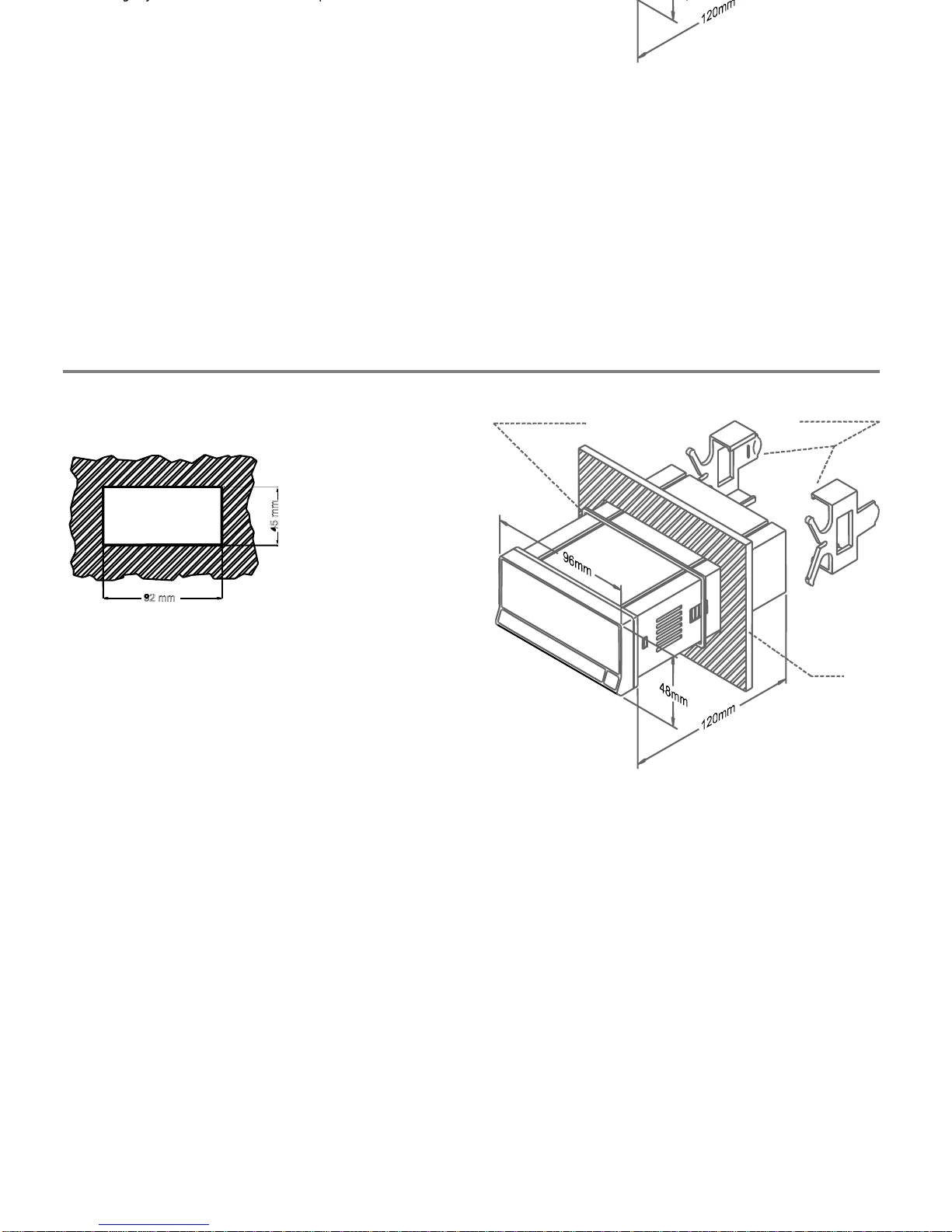
To install the instrument into the panel, make a 92x45 mm
cutout. Slide the sealing gasket over the rear of the unit to
the
bezel and insert the unit into the panel from the front.
Place the fixing clips on both sides of the case and slide
them over the guide tracks until they touch the panel at the
rear side.
Press slightly to fasten the bezel to the pane
l and secure the
clips in the slots of the case.
To take the instrument out of the panel, pull outwards the
rear tabs of the fixing clips to disengage and slide them
back over the case.
To install the instrument into the panel, make a 92x45 mm
cutout. Slide the sealing gasket over the rear of the unit to
the bezel and insert the unit i
nto the panel from the front.
Place the fixing clips on both sides of the case and slide
them over the guide tracks until they touch the panel at the
rear side.
Press slightly to fasten the bezel to the panel and secure the
clips in the slo
ts of the case.
To take the instrument out of the panel, pull outwards the
rear tabs of the fixing clips to disengage and slide them
back over the case.
53
53
7.3.
Dimensions and mounting
PANEL
FIXING CLIPS
SEALING GASKET
7.3.
Dimensions and mounting
PANEL
FIXING CLIPS
SEALING GASKET
Page 54
Manufacturer : DITEL - Diseños y Tecnología S.A.
Address :
Travessera de les Corts, 180
08028 Barcelona
ESPAÑA
Declares, that the product :
Description : Digital panel multifunction meter
Model :
BETA
-D
Conforms wit
h the directives :
EMC 89/336/CEE
LVD 73/23/CEE
Applicable Standards : EN50081-1 Generic emission
EN55022/CISPR22 Class B
Applicable Standards : EN50082-1 Generic immunity
IEC1000
-4-2
Level 3 Criteria B
Air Discharge 8kV
Contact Discharge 6kV
IEC1000
-4-3
Level 2 Criteria A
3V/m 80..1000MHz
IEC1000
-4-4
Level 2 Criteria B
1kV
Power Lines
0.5kV Signal Lines
Applicable Standars : EN61010-1 Generic Safety
IEC1010
-1
Installation Category II
Transient Voltages <2.5kV
Pollution Degree 2
Conductive pollution excluded
Insulation Type
Enclosure :
Double
Date: 8 March 2001
Signed: José M. Edo
Charge: Technical Manager
7.5.
CERTIFICATE OF CONFORMITY
Manufacturer : DITEL - Diseños y Tecnología S.A.
Address :
Travessera de les
Corts, 180
08028 Barcelona
ESPAÑA
Declares, that the product :
Description : Digital panel multifunction meter
Model :
BETA
-D
Conforms with the directives :
EMC 89/336/CEE
LVD 73/23/CEE
Applicable Standards : EN50081-1 Generic emission
EN55022/CISPR22 Class B
Applicable Standards : EN50082-1 Generic immunity
IEC1000
-4-2 L
evel 3 Criteria B
Air Discharge 8kV
Contact Discharge 6kV
IEC1000
-4-3
Level 2 Criteria A
3V/m 80..1000MHz
IEC1000
-4-4
Level 2 Criteria B
1kV Power Lines
0.5kV Signal Lines
Applicable Standars : EN61010-1 Generic Safety
IEC1010
-1
Installation Category II
Transient Voltages <2.5kV
Pollution Degree 2
Conductive pollution excluded
Insulation Type
Enclosure :
Double
Date: 8 March 2001
Signed: José M. Edo
Charge: Technical Manager
7.5.
CERTIFICATE OF CONFORMITY
54
54
Page 55

55
55
Page 56

56
56
Page 57

Page 58

Page 59

Page 60

DISEÑOS Y TECNOLOGI
A, S.A.
Polígono Industrial Les Guixeres
C/ Xarol 8 C
08915 BADALONA-SPAIN
Tel : +34 - 93 339 47 58
Fax : +34 - 93 490 31 45
E-
mail :
www.ditel.es
DISEÑOS Y TECNOLOGIA
, S.A.
Polígono Industrial Les Guixeres
C/ Xarol 8 C
08915 BADALONA-SPAIN
Tel : +34 - 93 339 47 58
Fax : +34 - 93 490 31 45
E-
mail :
www.ditel.es
This electronic instrument is covered by the
2002/96/CE
European Directive so, it is properly marked with
the crossed-out wheeled bin symbol that ma
kes reference to the selective collection for electrical and
electronic equipment which indicates that at the end of its lifetime, the final user cannot dispose of it as
unsorted municipal waste.
In order to protect the environment and in agreement with t
he European legislation regarding waste of
electrical and electronic equipments from products put on the market after 13 August 2005, the user can
give it back, without any cost, to the place where it was acquired to proceed to its controlled treatment and
recycling.
INSTRUCTIONS FOR THE RECYCLING
This electronic instrument is covered by the
2002/96/CE
European Directive so, it is pro
perly marked with
the crossed-
out wheeled bin symbol that makes reference to the selective collection for electrical and
electronic equipment which indicates that at the end of its lifetime, the final user cannot dispose of it as
unsorted municipal waste.
In order to protect the environment and in agreement with the European legislation regarding waste of
electrical and electronic equipments from products put on the market after 13 August 2005, the user can
give it back, without any cost, to the place wher
e it was acquired to proceed to its controlled treatment and
recycling.
Page 61
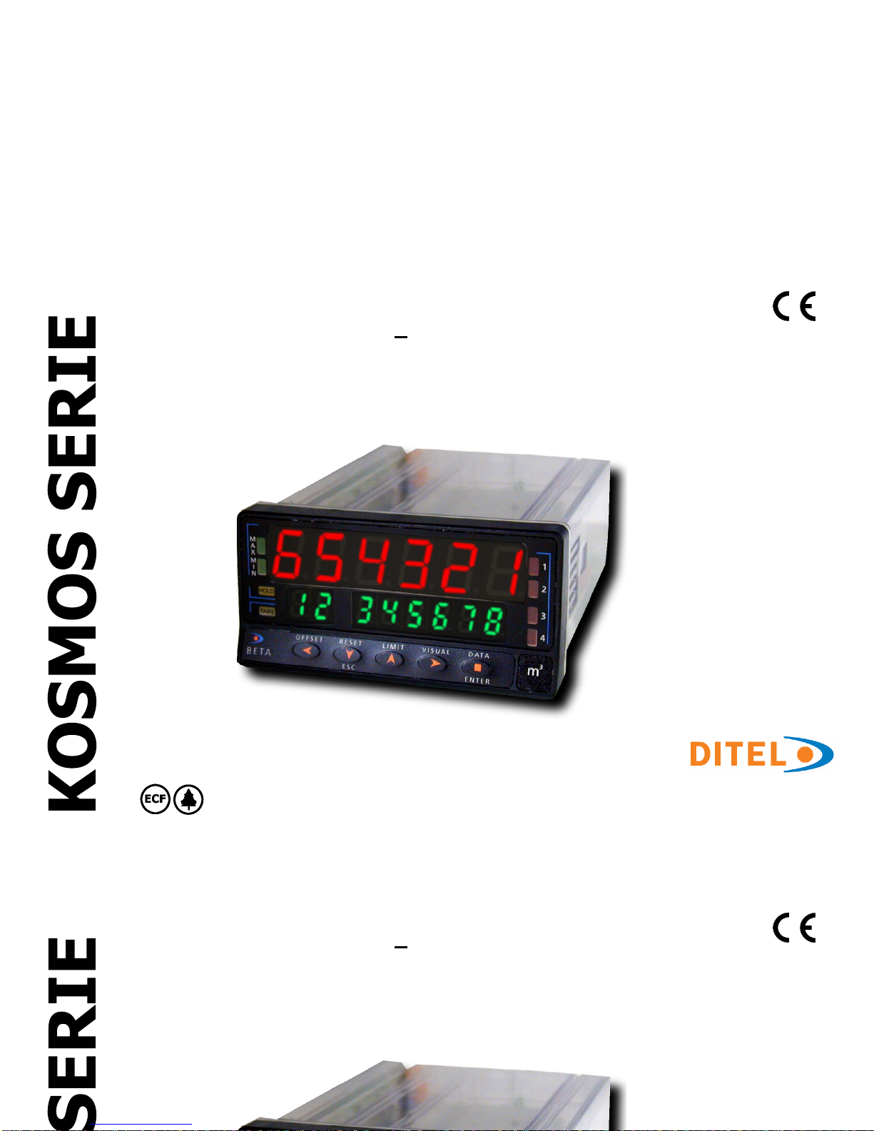
C
ODE: 3072
7126
EDI
TION
: 05-09-
200
6
INSTRUCTIONS MANUAL
COUNTER
TOTALIZER
TACHOMETER - TOTALIZER
PART 2 / 2
MODEL BETA-D
PROTOCOL MODBUS-RTU COMPA
TIBLE
INSTRUCTIONS MANUAL
COUNTER
TOTALIZER
TACHOMETER - TOTALIZER
PART 2
/ 2
Page 62

60
APPENDIX - INDEX
The output options are supplied in a separate way with its own instructions manual
describing installation card, wiring and electrical characteristics and the general instructions
for programming.
When the Tachometer option is active, this one will be the PROCESS variable ( or in 3
channels case, the PROCES
S variable), this is to say, the measurement of the speed
APPENDIX - INDEX
The output options are supplied in a separate way with its own instructions manual
desc
ribing installation card, wiring and electrical characteristics and the general instructions
for programming.
When the Tachometer option is active, this one will be the PROCESS variable ( or in 3
channels case, the PROCESS variable), this is to say, the
measurement of the speed
Setpoints
for counter
for Tachometer
Analog output
Serial output RS232C / RS485
61
62-69
70-75
77
79
Page 63

61
Programming and setpoints setup depends on if they are referred to the variable pulse counter or tachometer .
When the tachometer function is activated, this last will be the variable Process( or in three channel case, the variable Process
-
A), this
is to say the momentary speed.
SECTION
Referred to the Counter
A.1.
Programming diagram
62
APPENDIX A. SETPOINTS
Index
Programming and setpoints setup depends on if they are referred to the variable pulse counter or tachometer .
When the tachometer function is activa
ted, this last will be the variable Process( or in three channel case, the variable Process
-
A), this is to say the momentary speed.
SECTION
Referred to the Counter
A.1.
Programming diagram
62
A.2.
Setpoint setup and activation
63-67
A.3.
Output beha
vior definitions
A.3.1. Configuration
67-68
A.3.2. Operation diagram
69
Referred to the Tachometer
A.4.
Programming diagram
70
A.5.
Setpoint setup and activation
71-72
A.6.
Output behavior definitions
A.6.1. Configurations
73
-74
A.6.2. Operation diagram
75
APPENDIX A. SETPOINTS
Index
Page 64
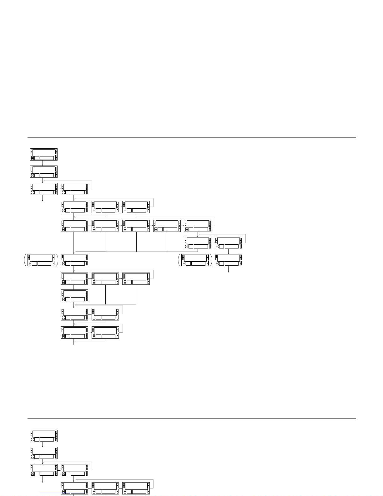
62
A.1. Programming SETPOINT 1 referred to a counter (valid for the rest of setpoints)
S E t P t S3 0
S E t 13 1
o n - o F F3 1
o F F
o n - o F F3 1
o n
c o M P3 1
P r o c
c o M P3 1
b t C H
c o M P3 1
t o t
PRO
A.1. Programming SETPOINT 1 referred to a counter (valid for the rest of setpoints)
S E t P t S3 0
S E t 13 1
o n - o F F3 1
o F F
o n - o F F3 1
o n
H I - L o3 1
H I
H I - L o3 1
L o
L E V E L3 1
9 9 9 9 9 9
A C t3 1
n o
A C t3 1
n c
t - o u t3 1
P u L S E
t - o u t3 1
L A t c H 1
t - o u t3 1
L A t c H 2
P u L S E3 1
9 9 9.9
PRO
M o d E3 1
I n d E P
M o d E3 1
r E S E t
M o d E3 1
S t o P
M o d E3 1
c L E A r
M o d E3 1
t r A c K
t r A c K3 1
A u t o
t r A c K3 1
S E t
L E V E L3 1
9 9 9 9 9 9
PRO
9 9 9 9 9 99 9
L E V E L
c o M P3 1
P r o c
c o M P3 1
b t C H
c o M P3 1
t o t
9 9 9 9 9 99 9
L E V E L
PRO
Page 65
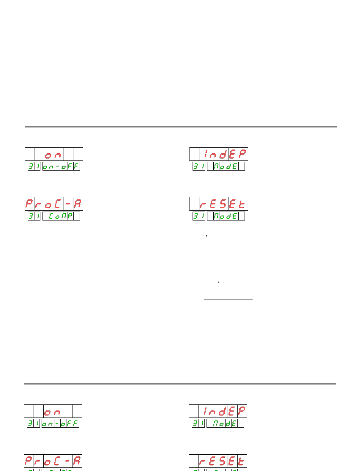
63
A.2. Ways of working
SELECTION ON-OFF
COMPARISON
FUNCTIONS
INDEP.
No action is done
A.2. Ways of working
SELECTION ON-OFF
COMPARISON
The setpoints can be referred to the PROCESS, BATCH or
TOTAL variables of any channel.
When are referred to any variable of C channel, the
comparis
on is done at the refreshing rate of this variable,
this is to say, every 10ms.
FUNCTIONS
At the setpoint activation, in addition to change the output
state, a specific action is done over the process that is
independently programmable for every setpoint
.
The action is only done on the activation edge of the
output, never when the alarm condition is already
established
FUNCTIONS
INDEP.
No action is done
RESET.
Puts to zero the var
iable referred by the setpoint
or, if it s the PROCESS value , to the preset value. (BATCH y
TOTAL have no preset, always are reset to zero).
1. In
PULSE
configuration the reset action is done in a cyclic
way, this is to say , the relay is activated on
setpoint value
reseting the counter and deactivating at the end of
programmed time. The operation is done again at every
reached of setpoint value as long as the activation time of
relay doesnt be longer than the time to pass again through
the setpoint.
2. In LATCH1 or LATCH2
configuration the relay activation
time should be minimum putting the counter to zero and
deactivating the relay immediately, this should be taken into
account when using this configurations.
Page 66
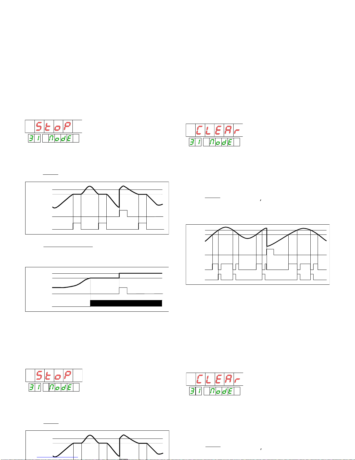
STOP.
Stops the counter. All coun
ter variables are hold ,
not only what is related to the setpoint.
1. In
PULSE
mode the counts stops only during the
activation time programmed, after that follows runing.
SET
OFFSET
CLEAR.
Deactivates the previous relay if is active at the
moment of this action. The previous setpoint for number 1
is number 4.
If the previous setpoint is not active when occurs the action,
this will activate in a normal w
ay when reach the condition.
2. In
PULSE
configuration the deactivated relay comes
back to be act iv e, if it s corresp ond ing , o nce th e
programmed activation time for this relay has finished
STOP.
Stops the counter. All counter variables are hold ,
not only what is related to the setpoint.
1. In
PULSE
mode the counts stops only during the
activation
time programmed, after that follows runing.
OUT SET
SET
RESET
PULSE
OFFSET
2. In LATCH1 y LATCH2
mode se para el contador
definitivamente y sólo reanuda la marcha cuando se realiza
un reset del contador. El contador arranca en el valor cero o
de offset.
SET
OFFSET
OUT SET
RESET
LATCH1-2
CLEAR.
Deactivates the previous relay if is active at the
moment of this action. The previous set
point for number 1
is number 4.
If the previous setpoint is not active when occurs the action,
this will activate in a normal way when reach the condition.
1. In
PULSE
configuration the deactivated relay comes
back to be act iv e, if it s corresp ond ing , o nce t
he
programmed activation time for this relay has finished
OUT2
OUT1
SET2
SET1
RESET
PULSE
64
Page 67
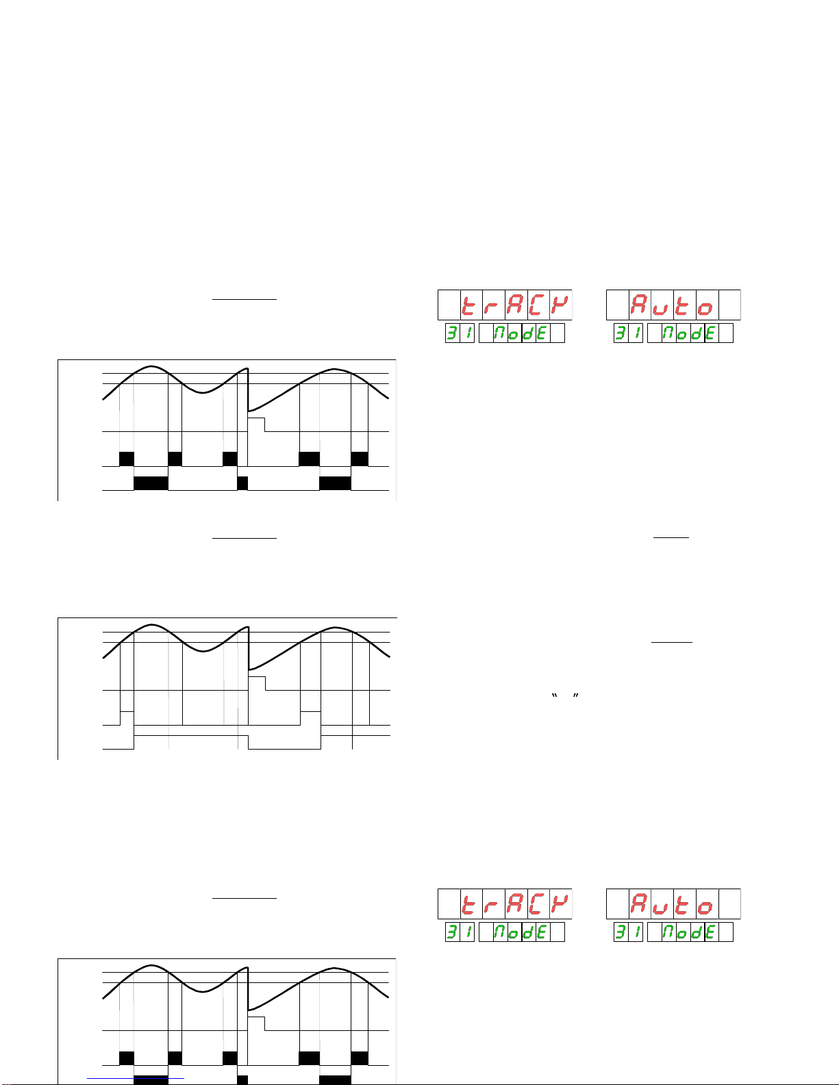
2. En la configuración
LATCH1
el relé
desactivado vuelve a activarse, si corresponde,
cuando cesa la condición de activación del relé
que efectúa la acción.
OUT1
LATCH1
SET2
SET1
RESET
TRACK AUTO
.
There is used to fit of automatic form the
quantity that, in a system of dosing, is programmed as limit
to give the order of cutting the flow of material. It is
necessary r
eset the display in every measurement (if the
setpoint is programmed in mode pulse) the reset will do of
automatic form). The accumulated whole is indicated in the
auxiliary display and, if is selected the function BATCH
2. En la configuración
LATCH1
el relé
desactivado vuelve a activarse, si corresponde,
cuando cesa la condición de activa
ción del relé
que efectúa la acción.
OUT2
OUT1
LATCH1
SET2
SET1
RESET
3. En la configuración
LATCH2
el relé
desactivado queda
permanentemente en este estado. Sólo podrá
volver a activarse, si corresponde, en un reset
que desenclave el relé que efectúa la acción.
OUT2
OUT1
LATCH2
SET2
SET1
RESET
TRACK AUTO
.
There is used to fit of automatic form
the
quantity that, in a system of dosing, is programmed as limit
to give the order of cutting the flow of material. It is
necessary reset the display in every measurement (if the
setpoint is programmed in mode pulse) the reset will do of
automatic form).
The accumulated whole is indicated in the
auxiliary display and, if is selected the function BATCH
RESET, the number of realized measurements will be
accumulated in the variable BATCH.
1.
To programme the setpoint in way
PULSE
allows to
realize this action
of automatic form calculating the
approximate time that is late in the display to be established
since the setpoint is reached until stops the process. This
time, or slightly large, will be programmed as time of
activation of the relay impulsional.
2.
Pr
ogramming the setpoint in way
LATCH
the action is
realized manually by the operator providing a reset as soon
as the display has become stable. In mode PULSE, it is
necessary to have the precaution of the setpoint
programmes in way LO in order that the r
elay is activated,
instead of be deactivating, after the time of programmed
impulse since the function is realized in the activation.
65
Page 68
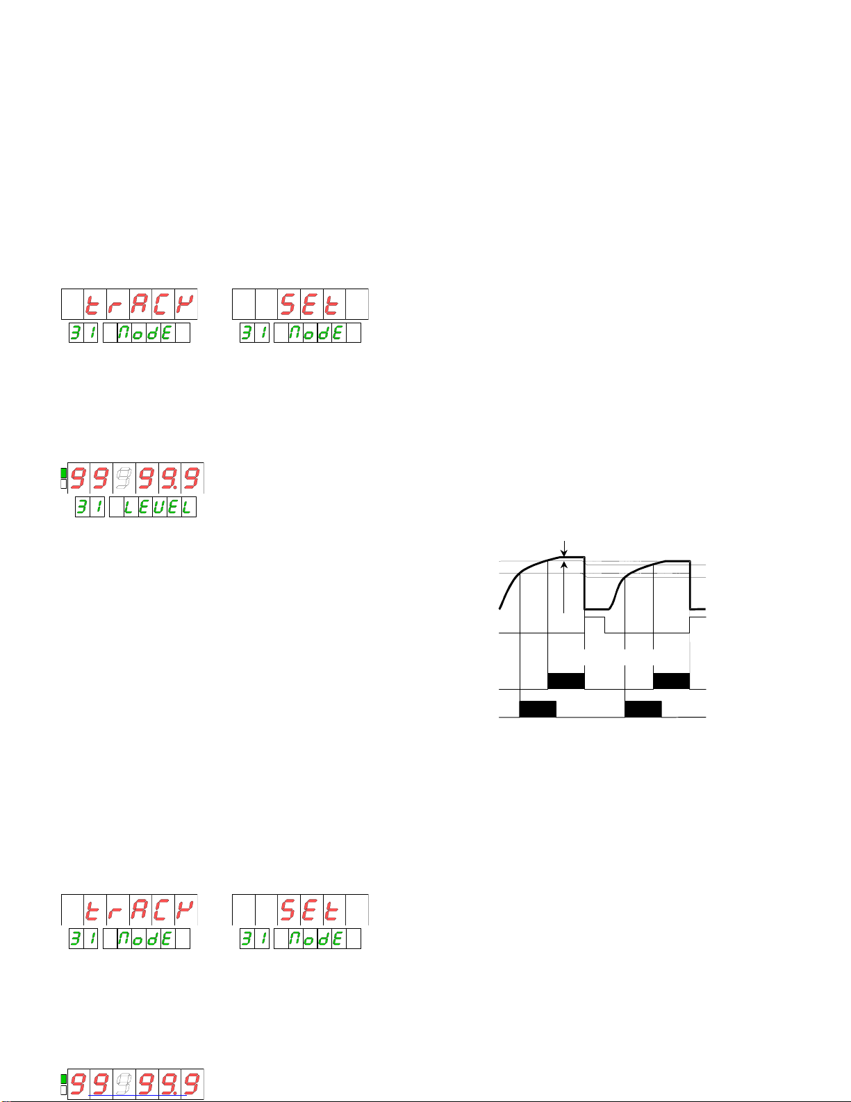
TRACK SET.
It is used as pre-alarm of the setpoint that
precedes in number. The setpoint that precedes the number
1 is the number
4.
The value of setpoint that is programmed in this case is the
distance in points with regard to the value of setpoint
precedent.
The output of the setpoint will take charge of the maneuver
of speed reduction of the machine (being activated when
the display coming to 95.0) and the output of the setpoint
will take charge of the maneuver of cuuting and sealing
when the d
isplay to come to 100.0.
SET1 = 100.0
(with function TRACK AUTO and way
PULSE, the reset would be automatic on having come to
100.0).
SETPOINT VALUE
The setpoint value are programmed on the whole range of
display, with polarity and with the decimal point o
n the
same position that the variable are referred.
When is referred to a PROCESS variable or
TRACK SET.
It is use
d as pre-alarm of the setpoint that
precedes in number. The setpoint that precedes the number
1 is the number 4.
The value of setpoint that is programmed in this case is the
distance in points with regard to the value of setpoint
precedent.
The value of display in which the output will be activated is
the value of the previous setpoint minus the programmed
value like track set. If it was negative, the output would be
activated in the value of the previous setpoint added with
t
he track set.
The parameters of functioning will be those of the main
setpoint.
We suppose that one machine that wraps reels of thread,
have to cut and seal the reels every 100.0 meters of thread
and that before, in order that these operations can be
real
ized, is necessary to reduce the speed of the rollers, for
example when a 5.0 meters lack to complete the process.
This application might be realized programming the setpoint
1 of value 100.0 and the setpoint 2 with function TRACK
SET of value 5.0.
The output of the setpoint will take charge of the maneuver
of speed reduction of the machine (being activated when
the display comin
g to 95.0) and the output of the setpoint
will take charge of the maneuver of cuuting and sealing
when the display to come to 100.0.
SET1 = 100.0
(with function TRACK AUTO and way
PULSE, the reset would be automatic on having come to
100.0).
SETPOINT VALU
E
The setpoint value are programmed on the whole range of
display, with polarity and with the decimal point on the
same position that the variable are referred.
When is referred to a PROCESS variable or
BATCH, its value is programmed with 6 digits on
main
display.
OUT1
OUT2
SET1
SET2
RESET
PULSE / LATCH1-2
SET1-excess
SET2-excess
excess
SET1 = 100.0
(with function TRACK AUTO and way
PULSE, the reset would be automatic on having come to
66
Page 69
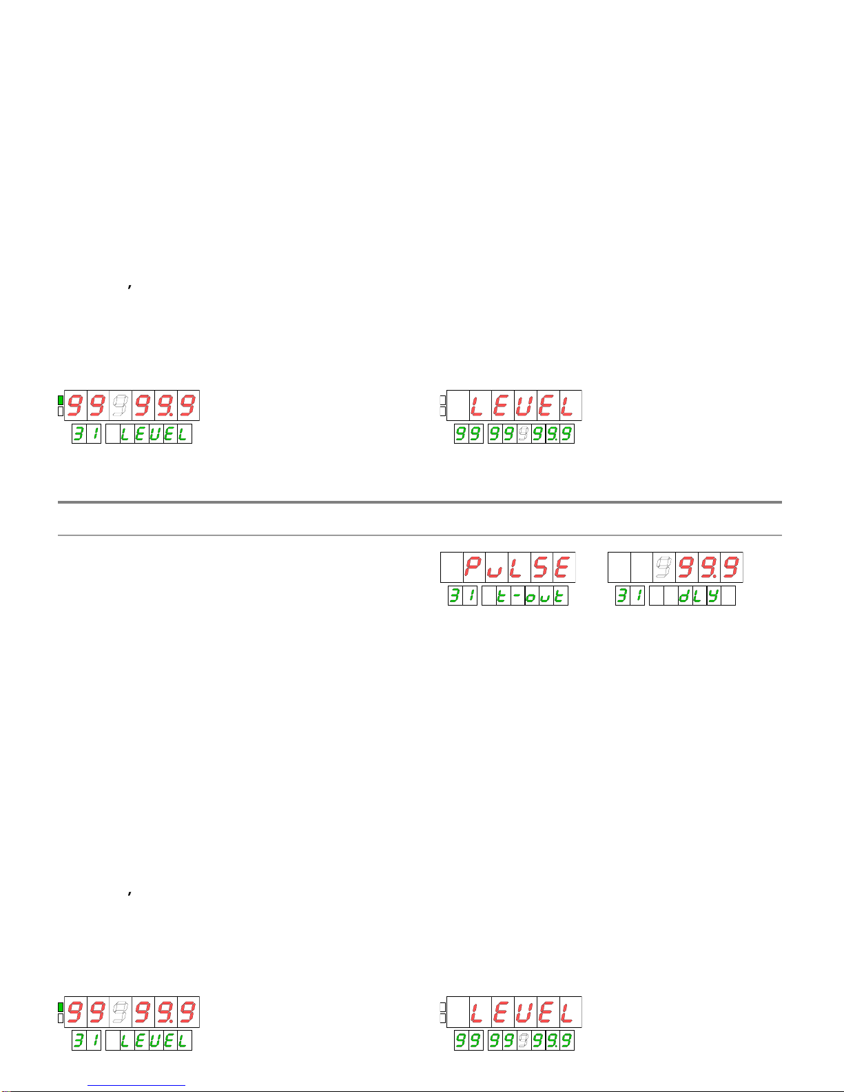
67
SETPOI NT S VALUE
The values of setpoint are programmed in the whole range
of display, with sign and with the decimal point in the
posi
tion of the variable to which they refer.
When is referred to the PROCESS or BATCH , its value is
programmed with 6 digits in the main display.
When it is referring to a TOTAL variable, its value is
programmed with 8 digits in the secondary display. The first
digit can be a number of 0 to 9 or one negative sign.
SETPOI NT S VALUE
The values of setpoint are programmed in the whole range
of display, with sign and with the decimal point in the
position of the variable to which they refer.
When is referred to the PROCESS or BATCH , its value is
programmed with 6 dig
its in the main display.
ACTIVATION TIME
The activation of an alarm of setpoint takes place in the
moment in which the display reaches the programmed
value.
The state of alert disappears, according to programming, of
th
ree different ways;
PULSE(deactivation after a programmed time),
LATCH1 (deactivation when stops the condition of alarm)
and
LATCH2 (deactivation when a reset is done)
When it is referring to a TOTAL variable, its value is
programmed with 8 digits in the secondary display. The first
digit c
an be a number of 0 to 9 or one negative sign.
PULSE
Activation when the display reaches the value of setpoint
already is in ascending (rising) or descendin
g sense.
The relay is not activated when in the connection of the
device or after a special action (reset, load) the display
takes the value of the setpoint.
Deactivation after the time of programmed impulse.
( Programmable from 0.1 to 999.9 seconds).
A.3. Output configuration
A.3.1. Configurations Pulse, Latch, HI
-
LO, NO
-
NC
Page 70
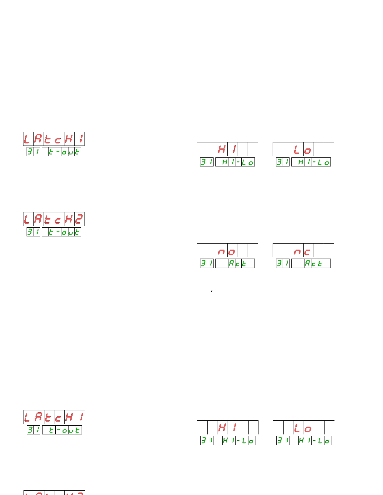
LATCH1
Activation
when the display is in a value that overcomes
the value of setpoint.
Deactivation
when the display goes on to a value below
the valu
e of setpoint.
MODE HI-LO
In mode
HI
the output is activated when the display is
equal or greater than the value of setpoint and is
deactivated when it is less.
In mode
LO
the output is deactivated when the display is
equal or greater than the value of setpoint and is activated
when it is less.
LATCH1
Activation
when the display is in a value that overcomes
the value of setpoint.
Deactivation
when the display goes on to a value below
the value of setpoint.
LATCH2
Activation
when the display is in a value that overcomes
the value of setpoint.
Interlock
in the flank of activation
of the relay, NOT when
the condition of alarm is established, in which case is
activated but it is not latched.
De-interlock.
Once activated and latched it will not be
deactivated when the condition of alarm stops but yes from
a reset of the variable to wh
ich it is referred providing that
the new value of display is not in condition of alarm, in
which case will be deactivated neither the relay nor unlatch.
Deactivation
. The form of de-
interlocking a relay without
reset the counter is to use the logical func
tion n º 24 (reset
relays latch), that de-
interlock all the relays and deactivates
those who are not in condition of alarm.
MODE HI-LO
In mode
HI
the output is activated when the display is
equal or greater than the value of setpoint and is
deactivated when it is less.
In mode
LO
the output is deactivated when the display is
equal or greater than the value
of setpoint and is activated
when it is less.
MODE NO-NC
NOT
(normally open) it means that the output of setpoint
will be deactivated in normal condition and activated in of
alarms condit
ion.
NC
(normally closed) means that the output of setpoint will
be activated in normal condition and will be deactivated
when it reaches the condition of alarm.
68
Page 71
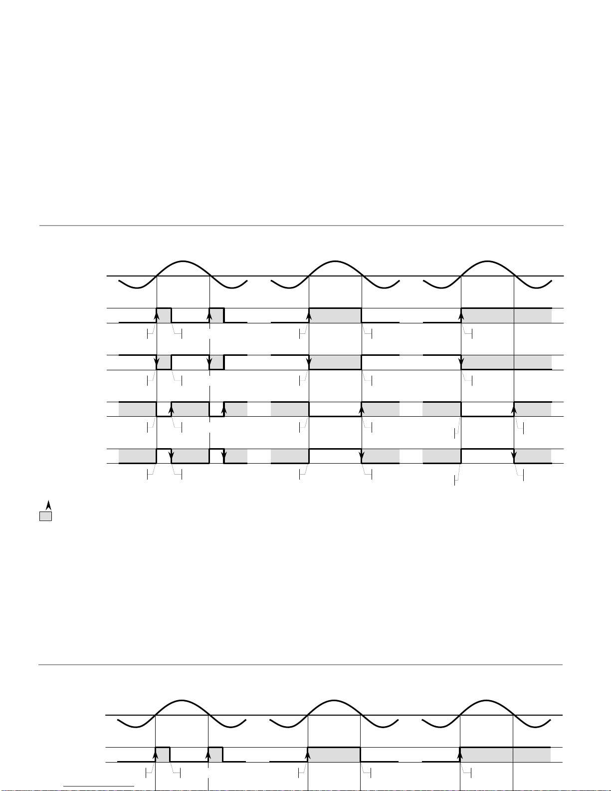
69
A.3.2. Summary diagram of ways of working
on
on
HI-LO=HI
ACT=NO
activate
deactivate
off
off
off
off
off
on
activate
deactivate
off
on
activate
setpoint
display
PULSE
LATCH
-1LATCH
-
2
A.3.2. Summary diagram of ways of working
ononoff
off
HI-LO=HI
ACT=NO
activate
deactivate
off
activate
deactivate
on
deactivate
activate
deactivate
activate
ononoff
off
off
on
offonoffonoffonoffonoff
offonononoff
off
offonononoff
activate
deactivate
activate
deactivate
deactivate
activate
deactivate
ac
tivate
offonon
off
off
offonononoff
activate
activate
deactivate
deactivate
setpoint
display
activate
activate
PULSE
LA
TCH-1
LATCH
-
2
HI-LO=HI
ACT=NC
HI
-
LO=LO
ACT=NO
HI-LO=LO
ACT=NC
: Activation edge of alarm where are done the setpoint functions (RESET, STOP, e
tc...) and where the relays make LATCH2
: Alarm zone
ON
: Relay and LED activated.
OFF
: Relay and LED deactivated.
Page 72
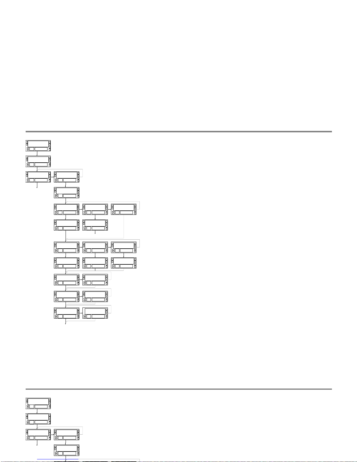
70
A.4. Programming setpoint 1 referred to the tachometer (rest of setpoints the same)
S E t P t S3 0
S E t 13 1
o n - o F F3 1
o F F
o n - o F F3 1
o n
c o M P3 1
P r o c
PRO
A
.4. Programming setpoint 1 referred to the tachometer (rest of setpoints the same)
S E t P t S3 0
S E t 13 1
o n - o F F3 1
o F F
o n - o F F3 1
o n
H I - L o3 1
H I
H I - L o3 1
L o
L E V E L3 1
9 9 9 9 9 9
A C t3 1
n o
A C t3 1
n c
t - o u t3 1
d L y
t - o u t3 1
H y S 1
t - o u t3 1
H y S 2
d L y3 1
9 9 9.9
PRO
d L y3 1
9 9 9 9 9.9
d L y3 1
9 9 9 9 9.9
L A t c H3 1
n o
L A t c H3 1
Y E S
M o d E3 1
I n d E P
M o d E3 1
t r A c K
L E V E L3 1
9 9 9 9 9 9
c o M P3 1
P r o c
M o d E3 1
S E n S E
PRO
PRO
Page 73
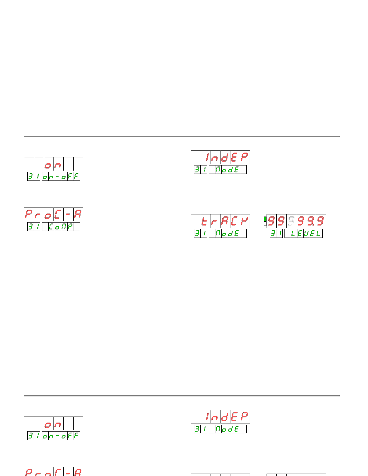
71
SELECTION ON-OFF
COMPARISON
INDEP.
In independent way, a value is pr
ogrammed of
display above or below which the alarm will be activated.
The value of setpoint corresponds to an instantaneous
speed and does not have sign.
A.5. Working ways
SELECTION ON-OFF
C
OMPARISON
If is wanted to refer one o more setpoints to the
instantaneous speed, the variable of comparison will have to
be PROCESS or, in case of 3 channels PROCESS-A.
SPECIAL FUNCTIONS
The setpoint referred to speed can ha
ve three specific
functions on the process such as control of value limit
(INDEP), pre-
alarm or safety alarm (TRACK) and indication
of sense of rotation (SENSE).
INDEP.
In independent way, a value is programmed of
display above or below which the alarm will be activated.
The value of setpoint
corresponds to an instantaneous
speed and does not have sign.
TRACK.
It is used as pre-
alarm or safety alarm of the
setpoint that precedes in number. The setpoint that
precedes the number 1
is the number 4.
The value to programming is the distance in points with
regard to the value of setpoint precedent.
The value of display in which the output will be activated is
the value of the previous setpoint fewer value programmed
like track.
If it wa
s negative, the output would be activated in the
value of the previous setpoint more of track set.
The parameters of functioning are not programmed but
they take directly of those of the main setpoint.
A.5. Working ways
Page 74
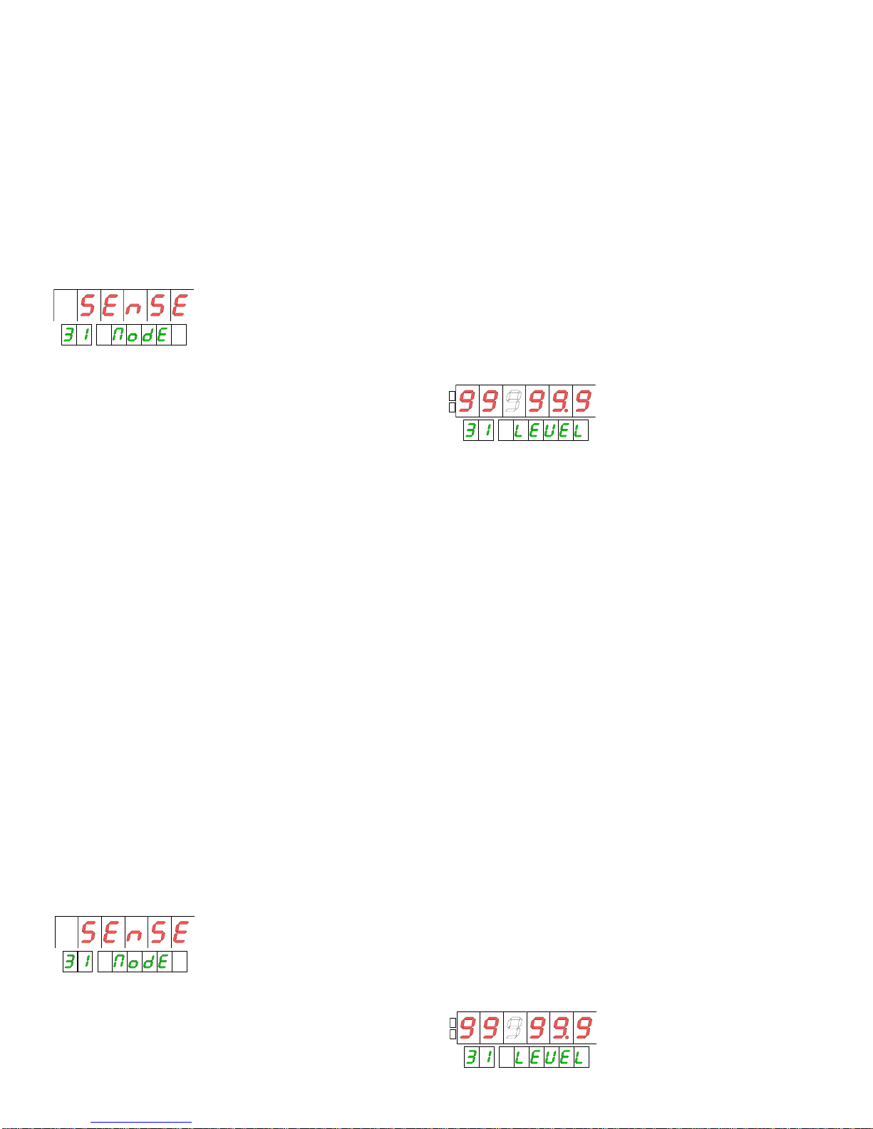
SENSE.
In mode SENSE, the setpoint is not referred to the
speed but to the sense of rotation.
The condition of
alarm takes place when the sense is negative
. That
the output is activated or not will come determined b
y the
parameters HI-LO and NO-NC.
The sense of rotation determines the direction of count of
the totalizer associated with the channel A, for that only the
SETPOINT VALUE
The values of setpoint for tachometer are referred to the
variable PROCESS A an
d are programmed without sign and
with the same decimal point that has this variable.
Depending on the setpoint function previously selected, the
programming of this value will be done of the following
SENSE.
In mode SENSE, the setpoint is not referred to the
speed but to the sense of rotation.
The condition of
alarm takes place when the sense is negative
. That
the output is activated or not will come determined by the
parameters HI-LO and NO-NC.
The sense of rotation determines the direction of count of
the totalizer associated with the channel A, for that only the
configurati
ons in which the channel A can count and
discount can indicate variation of sense.
These they are: 1 channel, modes 'up-
do', 'dir', 'PH1', 'PH2'
and 'PH4'.
SETPOINT
VALUE
The values of setpoint for tachometer are referred to the
variable PROCESS A and are programmed without sign and
with the same decimal point that has this variable.
Depending on the setpoint function previously selecte
d, the
programming of this value will be done of the following
ways:
IndEP
: is programmed the value of display where the
alarm must be activated.
TrACk
: is programmed of the number of points of display
for below or over the previous setpoint in which there
is
activated the alarm used as pre-alarm or safety alarm.
SenSE
: no value is programmed.
72
Page 75
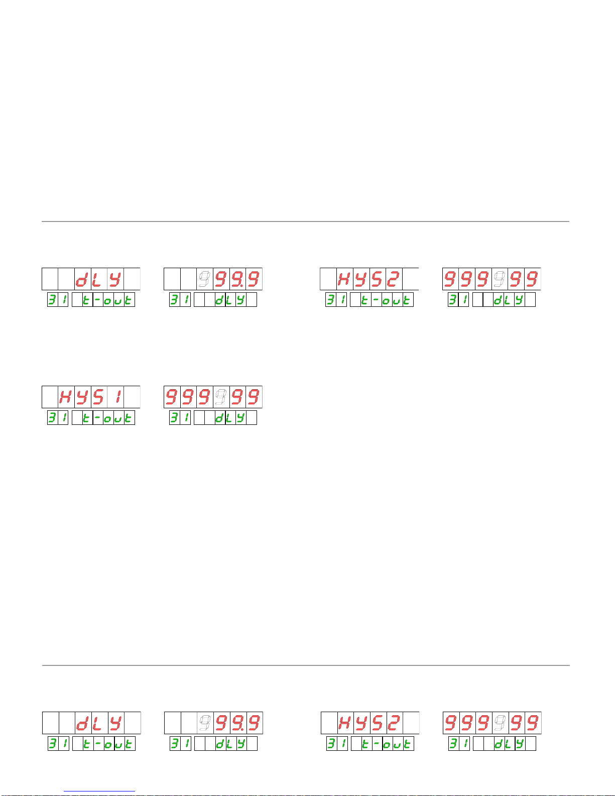
18
73
RANGE OF ACTIVATION
There
are three ways of activating the setpoint output:
DLY.
In way 'dly' delay, the output is activated with a
programmable delay when the condition of alarm having
taken place and maintained, is
deactivated with the same
HYS2.
In way 'hys2' (hysteresis symmetrical), the output is
activated a programma
ble number of points below the
setpoint and the same number of points is deactivated over
A.6.1. Output mode definition (delay
-
hysteresis, latch, hi
-
lo, no
-
nc)
RANGE OF ACTIVATION
There are three ways of activating the setpoint output:
DLY.
In way 'dly' delay, the output is activated with a
programmable delay when the condition of a
larm having
taken place and maintained, is deactivated with the same
delay on having eliminated the condition of alarm.
The time of delay is programmable of 0.1s to 999.9s
HYS1.
In way 'hys1'
(hysteresis asymmetric) the output is
activated in the value of setpoint and a programmable
number of points is deactivated below the setpoint.
The level of hysteteris is programmable in the whole range
of the display (0 to 999999) with the decimal point
in the
position of the display.
HYS2.
In way 'hys2' (hysteresis symmet
rical), the output is
activated a programmable number of points below the
setpoint and the same number of points is deactivated over
the setpoint.
The number of points is programmable of 0 to 999999 with
the decimal point in the position of the display. Th
e value to
programming will be the half of the total margin of
hysteresis, that is to say, supposing that the value of
setpoint was 1000 and the value programmed of hysteresis-
2 was 100, the range of display in that the alarm would be
activated between 900
and 1100.
A.6.1. Output mode definition (delay
-
hysteresis, latch, hi
-
lo, no
-
nc)
Page 76
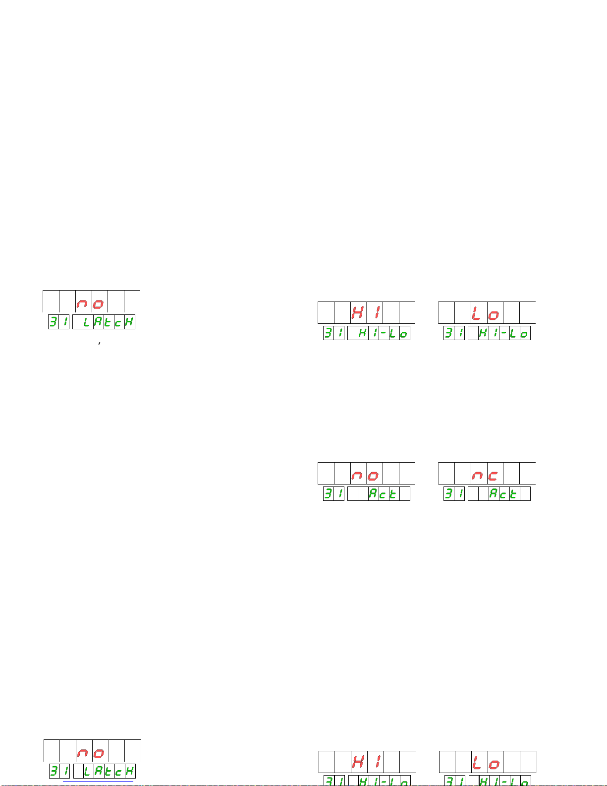
LATCH
The function latc
h is applied when it is necessary to keep an
alarm activated still when the condition of activation has
disappeared. For example to know if, at the conclusion of a
cycle of measurement, the process has exceeded in some
moment a value limit.
MODE HI-LO
In way
HI
the output is activated when the display is equal
or greater than the value of setpoint and is deactivated
when it is less.
In way LO
the output is deactivated when the display is
equa
l or greater than the value of setpoint and is activated
when it is less.
LATCH
The function latch is applied when it is nec
essary to keep an
alarm activated still when the condition of activation has
disappeared. For example to know if, at the conclusion of a
cycle of measurement, the process has exceeded in some
moment a value limit.
no
doest la
tch the output
YES Latch the output on the activation edge
When there is selected the option 'YES', the output of
setpoint is activated when the display reaches the
programmed value and it will not be deactivated any more
than in a disconnection of the de
vice or by means of the
logical function 26 (in rear conector ).
The output is activated but it is not latched if on having
connected the instrument, the display has a value that is in
condition of alarm. The latch takes place only in the edge of
activati
on of the output in a step along the setpoint.
MODE HI-LO
In way
HI
the output is activated when the display is equal
or greater than the value of setpoint and is deactivated
when it is less.
In way LO
the output is deactivated when the display is
equal or greater than the value
of setpoint and is activated
when it is less.
MODE NO-NC
NOT
(normally open) it means that the output of setpoint
will be deactivated in rest and activated in condition of
alarm.
NC
(norma
lly closed) means that the output of setpoint will
be activated in rest and will be deactivated when it reaches
the condition of alarm.
74
Page 77
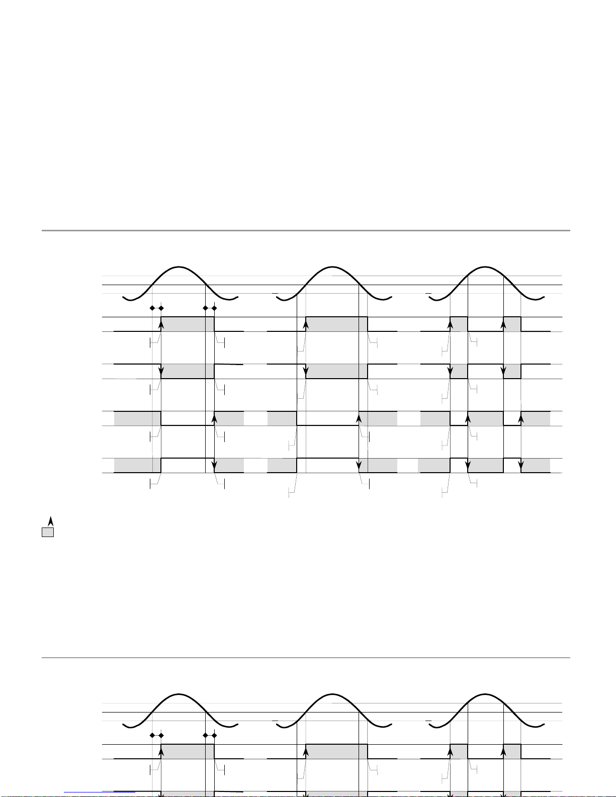
75
A.6.2. Summary diagr
am of ways of working
HI-LO=HI
ACT=NO
DELAY
HYSTERESIS
-1HYSTERESIS
-
2
t
t
activate
deactivate
off
off
off
off
off
on
activar
deactivate
off
off
activate
setpoint
display
setpoint
hyst
setpoint+hyst
setpoint
hyst
deactivate
off
off
on
on
off
t
t
A.6.2. Summary diagram of ways of
working
HI-LO=HI
ACT=NO
DELAY
HYSTERESIS
-1HYSTERESIS
-
2
HI-LO=HI
ACT=NC
HI-LO=LO
ACT=NO
HI-LO=LO
ACT=NC
t
t
activate
deactivate
off
activate
deactivate
on
deactivate
activate
deactivate
activate
off
on
o
ff
on
off
on
off
on
off
on
off
off
on
on
on
off
off
off
on
on
on
off
activar
deactivate
activar
deactivate
deactivate
activate
deactivate
activate
off
on
off
on
off
off
off
on
on
on
activate
activate
deactivate
deactivate
setpoint
display
activate
activate
setpoint
hyst
setpoint+hyst
setpoint
hyst
deactivate
deactivate
off
off
on
on
off
off
on
on
off
on
t
t
t
t
t
t
: Activation edge of alarm where are done the setpoint functions (RESET, STOP, etc...) and where the relays make LATCH2
: Alarm zone
ON
: Relay and LED activated.
OFF
: Relay and LED deactivated.
Page 78
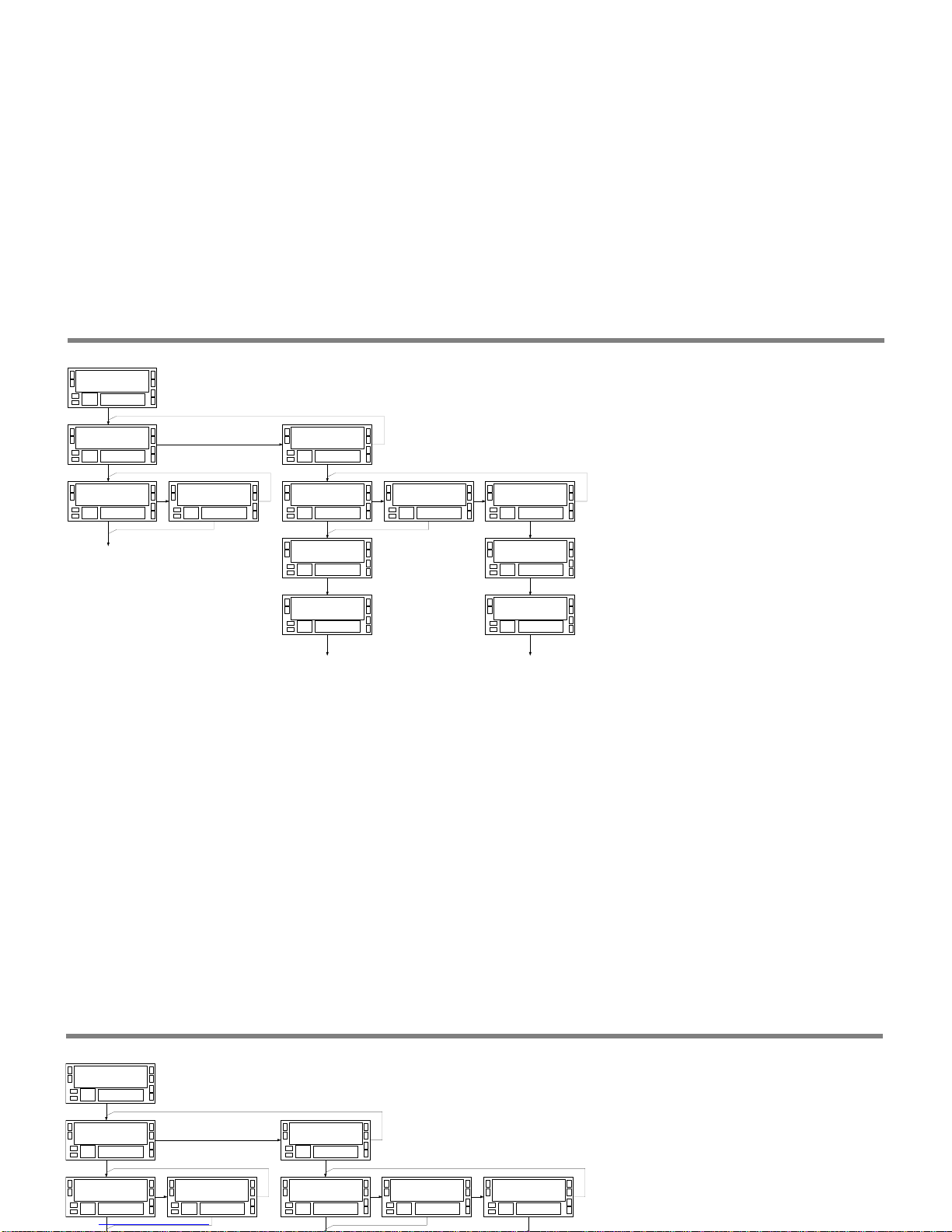
76
APPENDIX B. AN
ALOG OUTPUT
A n A o u t4 0
t Y P E4 1 S C A L4 2
t Y P E4 1
U d c
t Y P E4 1
I d c
c o M P4 2
P r o c
c o M P4 2
t o t
c o M P4 2
b t C H
APPENDIX B. ANALOG OUTPUT
The ana
logical exit is updated every 10ms.
The range of the output signal is programmed for any range
of display, being able to be selected like display the
PROCESS (counter or tachometer), the TOTAL or the BATCH
of anyone of the channels (providing that above m
entioned
variable is enabled).
A n A o u t4 0
t Y P E4 1 S C A L4 2
t Y P E4 1
U d c
t Y P E4 1
I d c
c o M P4 2
P r o c
A n A - H I4 2
9 9 9 9 9 9
c o M P4 2
t o t
A n A - L o4 2
9 9 9 9 9 9
9 9 9 9 9 99 9
A n A - H I
9 9 9 9 9 99 9
A n A - L o
PRO
PRO PRO
c o M P4 2
b t C H
Respect of the instructions of programming that are given in
the manual of the option, the menu has been eliminated
'FILTER' and the
prog
ramming of the scale has been
modified so that the output range to programming can refer
to any variable that the instrument has enabled.
If the variable is TOTAL, the ran
g
e is programmed in the
secondary display.
Page 79
77
APPENDIX C. SERIAL OUTPUT RS232C or RS485
PROTOCOLS
It is three protocols of communication represented by the
indication 'Prot-1', 'Prot-2' and 'Prot-3' that correspond to
the protocols DITEL, ISO 1745 and MODBUS respectively.
AVAILABLE COMMANDS
The list of commands that is given in the manual of the
option RS232C ó RS485 must be replaced by the following
one:
Commands
in protocol
1
2
3
hold+reset1
h
0h
h
SENDING INFORMATION TO A PRINTER
Throu
g
h the RS232C ó RS485 output also it is possible to
realize a selective transmission of information of the
instrument to a printer or a PC.
The lo
g
ical functions of printing allow to realize
transmissions from the instrument.
The
format of transmission
consists in:
a character of beginning of message followed by the
direction of the device,
APPENDIX C. SERIAL OUTPUT RS232C or RS485
PROTOCOLS
It is three protocols of communication represented by the
indication 'Prot-1', 'Prot-2' and 'Prot-3' that correspond to
the protocols DITEL, ISO 1745 and MODBUS respectively.
AVAILABLE COMMANDS
The list of commands that is given in the manual of the
option RS232C ó RS485 must be replaced by the following
one:
Commands
in protocol
1
2
3
hold+reset1
h
0h
h
reset relés latch
n
0n
n
reset de offset
r
0r
r
set offset
t
0t
t
reset1
z
0z
z
Data request in protocol
1
2
vallue of main display
D
0D
value of auxiliary display
T
0T
Data request and modification in
protocol
2
send setpoint # value
L#
modify setpoint #
value
M#
Request and modification of information
in protocol
3
All the information contained in the memory of the
instrument can be read and, if they are in a zone of allowed
writing, modified in blocks of up to 250 bytes. The writing is
limited to the area of information of programming of the
instrument. The reading does not have limitation.
SE
NDING INFORMATION TO A PRINTER
Throu
g
h the RS232C ó RS485 output also it is possible to
realize a selective transmission of information of the
instrument to a printer or a PC.
The lo
g
ical functions of printing allow to realize
transmissions from the instru
ment.
The
format of transmission
consists in:
a character of beginning of message followed by the
direction of the device,
a line in blank,
one or several lines containing the information
according to logical programmed function
And, if it has been selected to print date and hour
two lines in bla
nk,
a line with date and hour
To finish
a line in blank
The functions of
p
rinting and how to programme them they
are in the manual
p
resent in the section ' 5.2. Logical
programmable functions in connector ', pages.
43 to 46.
Page 80

78
The instruments are warranted against defective materials and workmanship for a period of
three
years from date of delivery.
If a product appears to have a defect or fails during the normal use within the warranty
period, please contact the distributor from which you purchased the product.
This warranty does not apply to defects resulting from act
ion of the buyer such as
mishandling or improper interfacing.
The instruments are warranted against defective materials and workmanship for a period of
three years from date of delivery.
If a product appears to have a defect or fails during the normal use within the warranty
period, please contact the dist
ributor from which you purchased the product.
This warranty does not apply to defects resulting from action of the buyer such as
mishandling or improper interfacing.
The liability under this warranty shall extend only to the repair of the instrument. No
responsibility is assumed by the manufacturer for any damage which may result from its
use.
All the DITEL products benefit from an unlimited and unconditional warrant
y
of THREE (3)
years from the date of their purchase. Now you can extend
this period of warranty up to
FIVE (5) years from the product commissioning, only by fulfilling a form.
Page 81

Page 82

Page 83

INSTRUCTIONS FOR THE RECYCLING
This electronic instrument is covered by the
2002/96/CE
European Directive so, it is properly mark
ed with
the crossed-out wheeled bin symbol that makes reference to the selective collection for electrical and
electronic e
quip
ment which indicates that at the end of its lifetime, the final user cannot dispose of it as
unsorted municipal waste.
In order to
p
rotect the environment and in agreement with the European legislation regarding waste of
electrical and electronic e
quip
ments from products put on the market after 13 August 2005, the user can
give it back, without any cost, to the place where it was ac
q
uired to proceed to its controlled treatment and
recycling.
INSTRUCTIONS FOR THE RECYCLING
This electronic instrument is covered
by the
2002/96/CE
European Directive so, it is properly marked with
the crossed-out wheeled bin symbol that makes reference to the selective collection for electrical and
electronic equipment which indicates that at the end of its lifetime, the final user cannot dis
p
ose of it as
unsorted municipal waste.
In order to
p
rotect the environment and in agreement with the European legislation regarding waste of
electrical and electronic equipments from products put on the market after 13 August 2005, the user can
 Loading...