

Ditek DTK-TSS3 User Manual
INSTALL INSTRUCTIONS
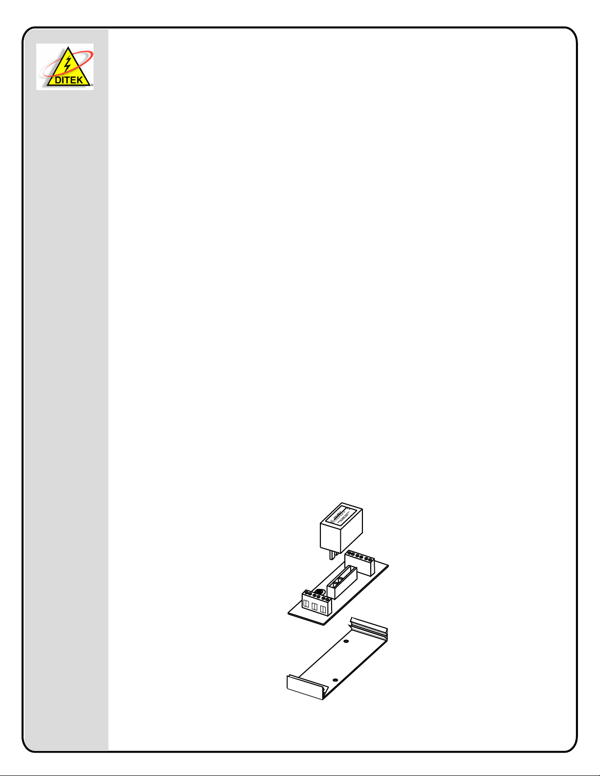
DTK-TSS3
DITEK Technical Support Available 24/7
1-888-472-6100
www.ditekcorp.com
DITEK Corporation
ONE DITEK CENTER
1720 Starkey Road
Largo, FL 33771
This Surge Protection Device (SPD) is a high performance device, designed to provide protection
for sensitive electronic loads connected to communication loop circuits that have been isolated
from the public switched telephone network or where the SPD is directly connected to the
electronic device. Maximum protection will only be achieved if the SPD is properly installed.
Please read and follow the installation instructions carefully.
NOTICE: This SPD should be installed by a qualified electrician in accordance with the National
and Local Electrical Codes and the following instructions.
APPLICATION
Surge suppression for hardwired series installations on 24 volt loop circuits or communication
circuits.
INSTRUCTIONS:
Caution: Measure all voltages to insure applied voltage does not exceed the voltage rating of
the unit. Improper installation voids the warranty.
NEMA ENCLOSURE MOUNTING
Enclosure can be mounted directly on to a panel, frame, or other mounting surface through
corner mounting holes. Corner hole mounting is required to maintain the NEMA 4X
rating.
DTK-2MHLP WIRING INSTRUCTIONS
1. Disable this circuit before beginning installation.
2. Remove 1/2" knockout on side of panel box.
4. Connect the supply wiring to the input terminals and connect the wiring of the protected
equipment to the output terminals. The base is rated for #12 AWG stranded maximum.
5. Allow 3 feet of conductor length between the base and the protected equipment. This will allow
unit time to react.
6. Make sure the wire distance from the base to protected equipment is greater than the wire
distance from the base to ground.
7. Connect ground lead to the ground terminal with 25 Ohms or less, use a minimum #14 AWG
wire. Use one common ground per system to avoid creating a differential in ground potential
or a ground loop.
8. After all connections have been made and no hazards exist, restore power.
G
N
D
1
+
1
-
2
+
2
-
I
G
N
N
P
D
U
T
INSTALLATION
Drawn By: J.Ramirez 2-06-06
Approved By: R. Mitchell 2-06-06
Doc # INT-100093-001
Part No. 191522 Rev. 1
 Loading...