

Ditek DTK-RM12POE, DTK-RM12POES Installation

DITEK Corporation
ONE DITEK CENTER
1720 Starkey Road
Largo, FL 33771
This Surge Protective Device (SPD) is a high performance device, designed to provide protection
for sensitive electronic loads connected to service panels, fire panels, or where the SPD is
directly connected to the electronic device. Maximum protection will only be achieved if the SPD
is properly installed.
Please read and follow the installation instructions carefully.
NOTICE: This SPD should be installed by a licensed contractor in accordance with the National
and Local Electrical Codes and the following instructions.
INSTALL INSTRUCTIONS
DTK-RM12POE / DTK-RM12POES
APPLICATION
Surge suppression for rack mount PoE Network Equipment and systems.
INSTRUCTIONS
Note: This device is intended to be installed indoors on the equipment rack closest to the point of use.
1. Test circuit prior to install to verify correct operation.
2. Turn off the power to the equiment to be protected.
3. This device can be mounted in a standard 19” equipment rack, or wall mounted using a hinged wall
mount bracket.
4. Connect to equipment ground using the ground lug provided on rear of faceplate. Use a minimum
#10 AWG wire.
Make sure the ground wire is as short as possible.
Ground Resistance Rule: Max ground resistance is 25 Ohms, 5 Ohms or less is optimum.
This cannot be an assumed value and must be measured to assure proper grounding.
5. Plug the RJ45 connector tipped cable from the field or supply wiring to the “IN UNPROTECTED”
RJ45 jack.
6. Plug a 3’ RJ45 male to RJ45 male patch cable from the “OUT PROTECTED” RJ45 jack to the
equipment to be protected. The 3’ patch cable will give this device time to react.
7. After all connections have been made and no hazards exist, restore power to the equipment.
Surge Module Replacement: This product is made up of 12 individual surge modules.
If 1 or more channels self sacrifice, you can replace that module as follows.
1. Power down the equipment before servicing this device.
2. Disconnect the ground wire from the ground lug located on the rear of the enclosure.
3. Remove the enclosure from its mounting and place on a flat surface.
4. Remove 4 screws holding front and rear cases together. Save these screws.
5. Remove the hardware from the specific module with the bad port , remove module. Be careful
to save all hardware.
6. Insert new surge module into openening aligning RJ45 connectors. The orientation should match the
previous module.
7. Replace hardware and tighten.
8. Join front and rear cases together and fasten with the screws previously removed.
9. Re-connect the ground wire to the ground lug on the rear of the enclosure.
10. Re-mount the enclosure.
11. After all connections have been made and no hazards exist, restore power to the equipment.
INSTALLATION
Drawn By: K. Nguyen 5-12-16
Revised By: R. Mitchell 5-16-16
DITEK Technical Support Available 24/7
www.ditekcorp.com
1-888-472-6100
Doc # INT-100108-001
Part No. 191532 Rev. 5
DITEK Corporation
ONE DITEK CENTER
1720 Starkey Road
Largo, FL 33771
INSTALL INSTRUCTIONS
DTK-RM12POE / DTK-RM12POES
Illustrations Page
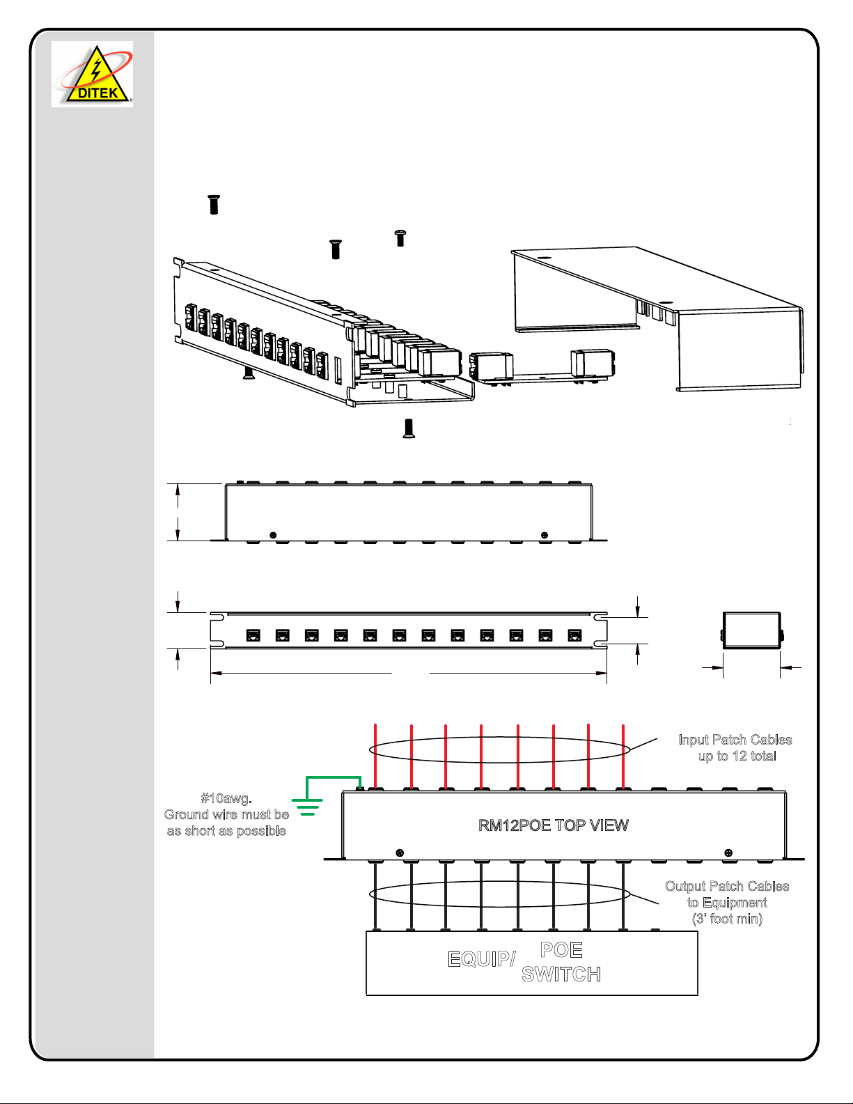
2.73
1.75
#10awg.
Ground wire must be
as short as possible
19.00
RM12POE TOP VIEW
POE
EQUIP/
SWITCH
1.25
2.73
Input Patch Cables
up to 12 total
Output Patch Cables
to Equipment
(3’ foot min)
INSTALLATION
Drawn By: K. Nguyen 5-12-16
Revised By: R. Mitchell 4-14-17
DITEK Technical Support Available 24/7
1-888-472-6100 www.ditekcorp.com
Doc # INT-100108-001
Part No. 191532 Rev. 5
 Loading...