

Ditek DTK-1LVLPLV, DTK-1LVLPSCPRUV, DTK-1LVLPX, DTK-2LVLAWGLV, DTK-2LVLPD User Manual
...
DITEK Technical Support Available 24/7
1-888-472-6100
www.ditekcorp.com
DITEK Corporation
ONE DITEK CENTER
1720 Starkey Road
Largo, FL 33771
INSTALL INSTRUCTIONS
DTK-LVLP SERIES
LOW VOLTAGE LINE PROTECTION
NOTE: This device is intended for indoor use on isolated loop circuits, data,
or low voltage telecommunication circuits.
1. Before beginning installation, discontinue power to the circuit.
2. This device must be connected in series between the field wiring and the
equipment to be protected.
3. Securely mount the base close to the circuit being protected using the
double sided tape (supplied), or two #8 screws (not supplied).
4. Allow the surge protector reaction time by providing 3-5 wire feet of distance
between the dtk- unit and the equipment to be protected.
5. Allow for the wire distance from the surge protector to protected
equipment to be greater than the wire distance from the surge protector to
INSTALLATION
ground.
6. Use one common ground per system to eliminate the possibility of a
difference in ground potentials.
7. Connect side #1 "in" with the incoming field wires, and connect the opposite
side of the terminal block to the equipment to be protected.
8. After all connections have been made and no hazards exist, restore power.
9. If you have any questions call technical support at: 1-888-472-6100.
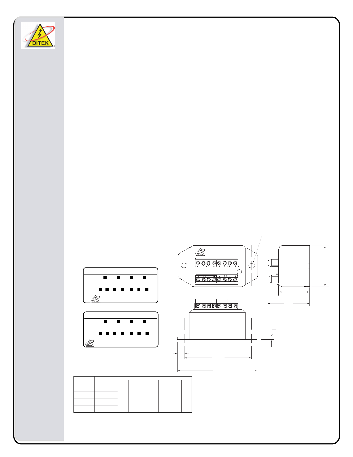
SLOT
0.180" x 0.240"
TYP. 2 PLACES
Side #1 "IN"
SUFFIX
VRMS
LOW VOLTAGE SURGE PROTECTION
Side #1 "IN"
MODEL DTK- 1LVLP 2LVLP 3LVLP 4LVLP
D X LV OPX SPK SGR RUV
SUFFIX
6 14 30 50 75 95 130
VRMS
LOW VOLTAGE SURGE PROTECTION
MODEL
DTK-1LVLP
DTK-2LVLP
DTK-3LVLP
DTK-4LVLP
# WIRES
PROTECTED
2 WIRES
4 WIRES
6 WIRES
8 WIRES
(SEE INSTRUCTIONS)
4LVLP3LVLP2LVLP1LVLPMODEL DTK-
RUVSGRSPKOPXLVXD
13095755030146
(SEE INSTRUCTIONS)
-SCP -SCP -SCP -SCP
95 75
S
G
R
VOLTS RMS
S
P
K
130
R
U
V
50 30 14 6
O
L
P
X
X
V
SURGE PROTECTION
1.555"
0.10"
0.20"
2.60"
3.00"
D
Doc # INT-100051-001
Part No. 191505 Rev. 5
1.60"
1.165"
 Loading...