

Page 1
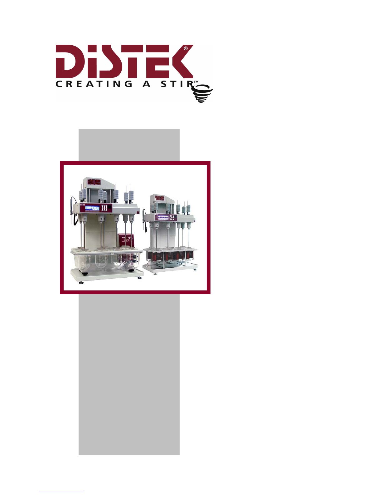
Operation
Manual
Evolution
Dissolution Test
System
6100
6300
Page 2

Evolution Dissolution Test System
Distek, Inc.
Operation Manual
Document # 3861-0001
121 North Center Dr. • North Brunswick, NJ 08902
Phone 732.422.7585 • Fax 732.422.7310
http://www.distekinc.com
Page 3

Notice
This document contains proprietary information. All rights are
reserved. No part of this document may be photocopied,
reproduced or translated without the prior written consent of
Distek, Inc.
Distek, Inc.
121 North Center Drive
North Brunswick, NJ 08902-4905
Tel. (732) 422-7585
Fax. (732) 422-7310
Website: http://www.distekinc.com
“Dow Corning” is a registered trademark of Dow Corning Corporation, USA.
CenterChek, HeightChek, RPMChek, ShaftChek and TempChek are trademarks of Distek,
Inc.
The Distek logo is a registered trademark of Distek, Inc.
All other company and product names are trademarks or registered trademarks of their
respective holders.
Document Revision History
Rev Date Notes
A June 2003 Initial Release
B December 2003 See Distek Change Notice 0405
C October 2004
D June 2005
E September 2005
F May 2007 See Distek Change Notice 0580. Updated for FW Rev. 2.15.
Updated for Firmware Rev. 2.13. See Distek Change Notice
0456.
Updated Appendix A: Spare Parts & Accessories. See Distek
Change Notice 0508.
Removed Certificate of Compliance from Manual. Certificate
is a separate file on manual CD. See Change Notice 0516.
Page B-1: Step # 5.3 – change “0.3V” to “2.0 V” and “0.5 V”
to “3.0 V”
Page D-2 and D-3 – add note to bottom of page - “Asterisk (*)
in Temperature Profiles denotes out of USP specification”
Page 4

Contents
About this Manual......................................................................... i
Purpose .................................................................................. ii
Audience ................................................................................ ii
Contents................................................................................. ii
Prerequisites............................................................................iii
Documentation .........................................................................iii
Conventions.............................................................................iii
1 Introduction ..................................................................... 1-1
Overview .............................................................................. 1-2
Specification.......................................................................... 1-2
Physical Site Considerations........................................................ 1-4
Environmental Considerations ..................................................... 1-5
Distek & the WEEE Directive (Waste Electrical & Electronic Equipment) 1-5
Ambient Laboratory Temperatures ............................................. 1-5
Ambient Laboratory Humidity ................................................... 1-6
Air Quality Considerations ....................................................... 1-7
Operation Warnings and Notes ..................................................... 1-8
General Instrument Overview ..................................................... 1-11
2 Installation....................................................................... 2-1
Unpacking ............................................................................. 2-2
Leveling the Evolution System ..................................................... 2-3
Installing the Thermocirculator (Evolution 6300 Only) ......................... 2-6
Placement and Connections ..................................................... 2-7
Filling the Water Bath ............................................................ 2-8
Priming the Pump ................................................................. 2-8
Operation Manual: Evolution Series
Page 5

Positioning the Vessels ............................................................. 2-10
Paddle and Basket Installation ....................................................2-11
Paddle Blade Installation........................................................2-11
Basket Installation ............................................................... 2-11
Checking Paddles, Baskets and Shafts for Straightness.....................2-12
Checking Shaft Centering ....................................................... 2-12
Paddles and Basket Height Adjustment..........................................2-12
Initial Height Setting for Paddles and Baskets: .............................. 2-13
Quick Change Height Adjustment Knob (Paddles or Baskets).............. 2-14
Installing the Calibration Probe................................................... 2-14
Installation Checkout...............................................................2-15
RPM Control .......................................................................2-15
Test Duration ..................................................................... 2-15
Temperature Control ............................................................2-16
Time and Date ....................................................................2-16
3 Operation ........................................................................ 3-1
Control Keypad ....................................................................... 3-4
ESC/DEL Button.................................................................... 3-4
RUN/STOP Button ................................................................. 3-4
Arrow Keys ......................................................................... 3-4
ENTER Button ...................................................................... 3-4
+ Button ............................................................................ 3-5
- Button ............................................................................. 3-5
Stir LED ............................................................................. 3-5
Heat LED............................................................................ 3-5
Sleep LED ........................................................................... 3-5
produKEY ........................................................................... 3-5
Startup Screens....................................................................... 3-5
System Administration .............................................................. 3-6
System Setup....................................................................... 3-7
Advanced Options .............................................................. 3-8
Unit Address ..................................................................... 3-8
TCS Address (Evolution 6300 Only)........................................... 3-9
Preheat (Evolution 6300 Only) ................................................ 3-9
Temperature Control (Evolution 6300 Only)............................... 3-10
Beep Mode ...................................................................... 3-10
Height Switch Setting ......................................................... 3-10
Printer Sharing Configuration (Evolution 6100 Only) ..................... 3-11
About Window.................................................................. 3-12
User Configuration ............................................................... 3-12
Login Procedures .............................................................. 3-13
Creating a New Account ...................................................... 3-14
Changing the Privileges of an Existing Account ........................... 3-15
Changing a Password .......................................................... 3-15
Deleting an Account........................................................... 3-16
Temperature Calibration........................................................3-16
Operation Manual: Evolution Series
Page 6

Calibrate Using Evolution Calibration Probe............................... 3-18
Calibrate Using TempChek Digital Thermometer ......................... 3-19
Calibrate Using NIST-Traceable Reference Thermometer ............... 3-19
Calibrate calPROBE Using TempChek Digital Thermometer ............. 3-20
Calibrate calPROBE Using NIST-Traceable Reference Thermometer... 3-21
Display Screens ......................................................................3-21
Temperature Screen ............................................................. 3-21
Temperature and RPM Screen .................................................. 3-22
Current Method...................................................................3-23
Report History .................................................................... 3-23
Printing a Saved Report .........................................................3-24
Working with Methods (Automatic Mode) .......................................3-24
Selecting a Method to Run ...................................................... 3-24
Sorting the Method List..........................................................3-25
Programming a New Method ....................................................3-25
Running a Simultaneous Drop with Paddles .................................. 3-27
Running a Simultaneous Drop with Baskets...................................3-28
Running a Staggered Drop with Paddles ...................................... 3-28
Running a Staggered Drop with Baskets....................................... 3-28
Open/View an Existing Method.................................................3-29
Modify a Saved Method ..........................................................3-30
Deleting a Method................................................................ 3-30
Copy a Saved Method to a New Name......................................... 3-30
Printing Method Parameters .................................................... 3-31
Working in Manual Mode ...........................................................3-31
Controlling Vessels Individually (Evolution 6100 Only) ..................... 3-32
Controlling All Vessels ...........................................................3-33
TCS Activation (Evolution 6300 Only) .........................................3-35
Running a Manual Mode Test ...................................................3-35
Using the produKEY ................................................................. 3-36
Saving a Method to the produKEY..............................................3-36
Viewing Methods on the produKEY............................................. 3-37
Saving a Method from the produKEY to the Instrument ....................3-37
Running a Method from the produKEY ........................................ 3-37
Deleting Methods from the produKEY .........................................3-38
Printing a Method from the produKEY.........................................3-38
Using a Premiere 5100 produKEY .............................................. 3-38
Using the calKEY ....................................................................3-38
Storing Calibration Data.........................................................3-39
Restoring Calibration Data ......................................................3-39
Printouts.............................................................................. 3-40
Serial Port Control ..................................................................3-40
4 Maintenance..................................................................... 4-1
General Information ................................................................. 4-2
Emptying the Water Bath & TCS (Evolution 6300 Only) ........................ 4-3
Removing the Water Bath (Evolution 6300 Only)................................ 4-4
Operation Manual: Evolution Series
Page 7

Re-installing the Water Bath (Evolution 6300 Only) ............................ 4-5
Replacing the Water Bath and TCS Tubing (Evolution 6300 Only) ............ 4-5
5 Troubleshooting................................................................. 5-1
Troubleshooting ...................................................................... 5-2
Error Messages....................................................................... 5-15
Warning Messages ...................................................................5-17
General Messages ................................................................... 5-18
Service................................................................................ 5-19
Appendix A : Spare Parts and Accessories ...................................... A-1
Appendix B : Pre-Installation Considerations: Electrical Power SupplyB-1
Appendix C : CE Declaration of Conformity .................................... C-1
Appendix D : Sample Printouts from Parallel Printer ......................... D-1
Operation Manual: Evolution Series
Page 8

About This Manual
i
About this Manual
About This Manual includes information about what is contained in this manual and
the conventions used.
Purpose .................................................................................. ii
Audience ................................................................................ ii
Contents................................................................................. ii
Prerequisites............................................................................iii
Documentation .........................................................................iii
Conventions.............................................................................iii
Operation Manual: Evolution Series
Page 9

About This Manual
ii
Purpose
This manual covers the installation, routine operation, maintenance and repair of
your Evolution Dissolution Test System. It has information regarding the
commands, menus, indicators and controls. Chapter 1 provides an overview of the
system. Chapter 2 covers unpacking, installation, and qualification of the system.
Chapter 3 has operation and programming information. Chapters 4 and 5 cover
maintenance and troubleshooting. Please read Chapters 1, 2 and 3 before
proceeding.
Audience
This manual is written for any person responsible for maintaining, operating or
troubleshooting the Distek Evolution Dissolution Test System.
Contents
This manual is divided into chapters. The pages of the manual are numbered
providing easy navigation to assist in finding information quickly.
The following list describes the material covered in each chapter:
Chapter 1 - Introduction Provides a general overview and
warnings about the instrument.
Chapter 2 - Installation Describes how to unpack and properly
install the unit.
Chapter 3 - Operation Describes the functionalities of the
system and how to run the unit.
Chapter 4 - Maintenance Explains the steps necessary to
maintain the unit.
Chapter 5 - Troubleshooting Provides a troubleshooting chart and
description of error messages to assist
the user if a problem arises.
Appendix A – Spare Parts and
Accessories
Appendix B - Pre-Installation
Considerations: Electrical Power
Supply
Appendix C - CE Declaration of
Conformity
Appendix D - Certificate of
Compliance
Appendix E - Sample Printouts from
Parallel Printer
Provides a table of recommended and
optional spare parts.
Recommendation information
pertaining to electrical power supply.
CE Declaration of Conformity
certificate.
Certificate of Compliance
Sample printouts for a parallel printer.
Operation Manual: Evolution Series
Page 10
About This Manual
iii
Prerequisites
This manual assumes that you understand the principles of dissolution testing.
Documentation
This manual contains important information regarding the safe operation,
maintenance and repair of your Distek Evolution Dissolution Test System.
Conventions
The following table contains Warnings, Cautions and Notes that are used
throughout the document for your protection. Please read this section before
using the Evolution Dissolution Testing System.
REQUIRED
ACTION
“WARNING” statements are used in this manual to prevent
injury to personnel.
"CAUTION: Risk of Electric Shock" statements are used to
prevent injury when high voltage is present.
“CAUTION” statements are used to prevent damage to
equipment.
“NOTES” contain helpful information.
“REQUIRED ACTION” is used where necessary to distinguish
the action needed from Warnings, Cautions and Notes.
Operation Manual: Evolution Series
Page 11

Chapter 1: Introduction
1-1
1111 Introduction
The Distek Evolution Dissolution Test System is a state of the art instrument. This
chapter will provide an overview of the unit and system specific specifications.
Overview .............................................................................. 1-2
Specification.......................................................................... 1-2
Physical Site Considerations........................................................ 1-4
Environmental Considerations ..................................................... 1-5
Distek & the WEEE Directive (Waste Electrical & Electronic Equipment) 1-5
Ambient Laboratory Temperatures ............................................. 1-5
Ambient Laboratory Humidity ................................................... 1-6
Air Quality Considerations ....................................................... 1-7
Operation Warnings and Notes ..................................................... 1-8
General Instrument Overview ..................................................... 1-11
Operation Manual: Evolution Series
Page 12

Chapter 1: Introduction
1-2
Overview
Distek is once again setting the standard by which all dissolution systems will be
measured. The new Evolution Series is taking dissolution testing to the next level
by advancing the state of the art design of its predecessor, the highly successful
Premiere Model 5100.
The Evolution Series is designed to meet today's demanding standards for accurate
temperature control and test result reporting. The enhanced user interface offers
a rich array of features and functionality, greatly improving the dissolution
chemist's productivity and control over the dissolution test. The Evolution has
menu driven navigation for ease of setup, manager and user log-in levels, 100
sorted methods and up to 40 test report storage.
Specification
Table 1-1: Evolution Specifications
Evolution 6100
Bathless
Dissolution Vessels Six Standard/
Up to Seven Vessels
Volume 500mL - 1000mL
programmable
Six Standard/
Up to Seven Vessels
500mL - 1000mL
programmable
Evolution 6300
Water Bath
Vessel Heating Rate Approx. 1.5°C per minute Approx. 0.3°C per minute
RPM Control Range 25-300 RPM, digitally
controlled, closed loop
25-300 RPM, digitally
controlled, closed loop
Resolution 0.1 RPM 0.1 RPM
Accuracy ±0.2 RPM ±0.2 RPM
Display LED's, .75” (19mm) high LED's, .75” (19mm) high
Motor High Torque, Permanent
Magnet
High Torque, Permanent
Magnet
Vessel Temperature
Control
Independently controlled
two-zone heater jackets
TCS Thermocirculator
Display Resolution 0.01 °C 0.01 °C
Accuracy ±0.25 °C* ±0.25 °C at 37.0 °C
Calibration Built-in Calibration Probe Built-in Calibration Probe
Operation Manual: Evolution Series
Page 13

Chapter 1: Introduction
1-3
Evolution 6100
Bathless
Evolution 6300
Water Bath
Shaft Wobble Less than 0.010” (0.254mm)
Total Indicator Runout
Less than 0.010” (0.254mm)
Total Indicator Runout
Program Modes Manual
(Individual Vessel Control)
Automatic
(Up to 100 Pre-Programmed
Methods)
External
(produKEY™ Memory Device)
Manual
(Individual Vessel Control)
Automatic
(Up to 100 Pre-Programmed
Methods)
External
(produKEY™ Memory Device)
Interface Ports RS-232 (2), RS-485 (1),
Parallel Printer (1)
RS-232 (2), RS-485 (1),
Parallel Printer (1)
Construction
Materials
Cast Aluminum, Stainless
Steel, Acid resistant solid
state heating elements,
Engineered Plastics
Cast Aluminum, Stainless
Steel, 316 Stainless Steel
heating elements,
Engineered Plastics
Dimensions 26”(W) x 39”(H) x 20”(D)
(66cm x 99cm x 51cm)
26”(W) x 39”(H) x 20”(D)
(66cm x 99cm x 51cm)
TCS: 7" w x 16" h x 7" d
(18cm x 41 cm x 18 cm)
Weight 150 lb. (67.5 kg) 150 lb. (67.5 kg)
(Empty Water Bath)
TCS: 16 lb. (7.3 kg)
Electrical Power 115V ± 15V 50/60Hz 15A
or
230V ± 15V 50/60Hz 9A
(Operating voltage pre-set at
factory)
115V ± 15V 50/60Hz 3A
or
230V ± 15V 50/60Hz 3A
(Operating voltage pre-set at
factory)
TCS:
115V ± 15V 50/60Hz 8A
or
230V ± 15V 50/60Hz 5A
* Test Setting: Paddles, 900 mls, 50 RPM
Operation Manual: Evolution Series
Page 14

Chapter 1: Introduction
1-4
Physical Site Considerations
The dimensional requirements specified below are adequate for the installation of
the Evolution Dissolution System:
1. The minimum bench depth (front edge of bench to the back splash or wall)
needed is 22” (0.56m). However, the minimum recommended bench depth is
23” (0.59m). For manual sampling, 29” (0.74m) is recommended to allow room
in front for the receiving flasks or tubes into which the measured volumes of
sample are to be collected.
2. The minimum linear bench space requirement is 33” (0.84m). Distek
recommends that at least 39” (1.0m) be allocated whenever manual operations
are required to be performed adjacent to the system.
3. There must be no obstruction (cabinet, shelf, or outlet) that intrudes into the
minimum footprint of the unit up to a height of 40” (1.02m) above the bench
surface where the unit is to be installed.
4. The bench must be capable of sustaining the weight of the unit and all of its
accessory parts without significant bending. Because the entire mass of the
unit is transferred to the bench surface through three (3) circular padded,
adjustable leveling feet, the bench surface should be strong enough to
withstand a load of 60 pounds per square inch (4 kilograms per square
centimeter).
5. Because of the limitation in travel of the leveling feet, the bench slope should
be less than 0.75” (1.9cm) from front to back or from side to side over the
unit’s foot print.
Operation Manual: Evolution Series
Page 15
Chapter 1: Introduction
1-5
Environmental Considerations
Distek & the WEEE Directive (Waste Electrical & Electronic Equipment)
Distek, Inc. is committed to protecting the environment and
understands the importance of proper recycling. The “crossed
out wheelie bin” symbol on the product or on its packaging
indicates that this product must not be disposed of with domestic
household waste. Instead, it is the user’s responsibility to dispose
of their waste equipment by handing it over to a designated
collection point for the recycling of electrical and electronic
equipment waste. The separate collection and recycling of your
waste equipment at the time of disposal will help to conserve
natural resources and ensure that it is recycled in a manner that
protects human health and the environment.
For more information about where you can drop off your waste equipment for
recycling, please contact your local city office, your local distributor or Distek,
Inc.
Ambient Laboratory Temperatures
Distek recommends that the laboratory
temperature control system fans be kept on at all
times. This should improve set point control, and
minimize short-term excursion range.
Maximum Conditions:
1. To achieve the full range of controlled operation (30 to 45°C) within
specified tolerances the Evolution Dissolution System is designed to be
installed and operated in laboratories where the maximum operating
temperature does not exceed 25°C.
2. The maximum allowable ambient operation temperature is 30°C.
Operating environments above 25°C limit the range
for satisfactory operation of system to between 35
and 45°C.
Operation Manual: Evolution Series
Page 16
Chapter 1: Introduction
1-6
Minimum Conditions:
To assure controlled operation within specified tolerances, the Evolution
System is designed to be operated in laboratories where minimum operating
temperatures do not drop below 15°C.
Variability or Short Term Fluctuations:
To assure controlled operation within specified tolerances, the system used
to control the temperature of the laboratory where the Evolution System is
installed must be able to maintain the ambient air temperature within ±2.5°C
of set point (worst case).
Thermal Loading:
For laboratories where temperature control is critical,
installation of several dissolution units may require that
the system be re-balanced. Thermostats may need to
be relocated to maintain temperature uniformity in the
lab.
1. Each unit contributes an average thermal load of about 0.6 kW when
operating. The lab’s cooling systems must have sufficient excess cooling
capacity to handle the aggregate thermal load for all systems installed.
2. The heating system must also be able to respond to the increased loading
from the units by appropriately throttling back.
Ambient Laboratory Humidity
Distek recommends that the laboratory humidity control
system fans be kept on at all times if possible. This
should result in better set point control and reduce the
short term excursion range.
Maximum:
The Evolution System may add to the humidity of the laboratory during
operation. The bathless design (6100 only) reduces humidity compared to
other models, but any vessels filled and left uncovered can raise humidity
levels. Water vapor and/or hydrogen chloride vapor, from dissolution media,
can cause serious effects when condensed on electrical components and
contacts. The lab’s environmental controls should maintain the humidity
level below the dew point, to minimize the risk of condensation.
Minimum:
Operation Manual: Evolution Series
Page 17

Chapter 1: Introduction
1-7
The Evolution System utilizes solid-state semiconductor devices. It is
important that the humidity level be kept at or above 30% relative humidity,
to minimize the risk of damage to control circuits caused by static discharge.
Air Quality Considerations
Distek dissolution systems are designed to be operated in a lab environment that
has no visible dust problem, and with organic solvent vapor levels as low as
possible. Operation is not recommended in dusty lab environments, or in labs with
significant chlorinated or reactive solvent vapor levels. These dust or vapor levels
may have serious effects on system components. Absorption of vapors into
dissolution media may bias test results. Some dissolution tests may require
dissolution and drug release media prepared from USP quality water. Absorbed
vapors may cause difficulty in complying with USP requirements.
Operation Manual: Evolution Series
Page 18
1-8
Operation Warnings and Notes
For your safety, the information in this
manual must be followed to minimize the risk
of fire or explosion, electrical shock, or to
prevent property damage, personal injury or
loss of life.
Use this equipment only for its intended
purpose as described in this Operation Manual.
Never attempt to operate this instrument if it
is damaged, malfunctioning, partially
disassembled, or has missing or broken parts,
including a damaged cord or plug.
Improper servicing or adjustment practice can
cause equipment failure or serious physical
injury. This equipment must be adjusted and
serviced by qualified electrical maintenance
personnel who are familiar with the
construction and operation of the equipment
and the hazards involved. Take diligent care
during adjustment. All exposed points on the
control circuit boards are electrically hot with
respect to earth ground.
HIGH VOLTAGE IS EXPOSED WHEN THE
LOWER REAR PANEL IS OPENED ON THE
DISSOLUTION SYSTEM. Dangerous voltages
exist on the circuit boards when powered.
Disconnect AC power from the system while
troubleshooting. Be alert. High voltage can
cause serious or fatal injury.
All Distek Evolution 6100 heaters have
thermostatic protection. In the event of a
malfunction (or if no liquid in vessel), the
heater will cut off at approximately 150ºC.
Thermostat automatically resets after cooling
down.
Take proper precautions when handling
dissolution media. Liquid in vessel may be
HOT. Wear splash protection to avoid
exposure to scalding, acidic, caustic, or
pharmaceutical hazards. Bacteria have been
shown to thrive in certain media, especially at
test temperatures.
Chapter 1: Introduction
Operation Manual: Evolution Series
Page 19
Chapter 1: Introduction
1-9
The heating of aggressive media can cause
explosion, implosion, release of toxic or
flammable gases. Appropriate cautions should
be taken.
The Evolution Dissolution System is capable of
utilizing all of the commonly used dissolution
media such as 0.1 HCL, phosphate buffers and
sodium lauryl sulphate.
In the event of a hazardous material spill on
the external surface of the instrument, the
unit can be cleaned with a disposable cloth or
paper wipe, then rinsed and dried with water.
The same approached can be used for internal
spill but the power must be disconnected first!
Before using any cleaning or decontamination
method recommended by the manufacturer,
users should check with the manufacturer that
the purpose method will not damage the
equipment.
Heater surfaces may be HOT. Do not touch
vessel heater assemblies when 6100 is in
operation. Injury may result.
Improper remote PC control of the Evolution
system may lead to unexpected motor and/or
heater operation.
To avoid glass breakage and injury:
• Do not heat vessel empty.
• Do not clean with materials that scratch.
• Do not bump.
Discard vessels if cracked, scratched or
excessively heated empty.
The Evolution system incorporates a height sensor to
stop rotation and adjust heating whenever the drive
unit is raised well above operating position. This
feature helps to prevent overheating and addresses
safety issues.
Operation Manual user interface screen shots may
vary from actual instrument interface screens.
Operation Manual: Evolution Series
Page 20
1-10
CAUTION: TO AVOID DAMAGING THE INSTRUMENT
Chapter 1: Introduction
• DO NOT OPERATE 6100 HEATERS WITH LESS THAN 500mL
LIQUID IN EACH VESSEL.
• THE STIRRING ELEMENT (Paddle or Basket) MUST BE
IMMERSED INTO THE LIQUID AND ROTATING WHEN
HEATERS ARE OPERATING.
• USE ONLY GLASS VESSELS SUPPLIED FOR THE EVOLUTION
SYSTEM BY Distek.
• CONNECT THIS UNIT TO THE SPECIFIED AC SUPPLY.
OBSERVE PROPER GROUNDING.
♦ FAILURE TO OBSERVE THESE PRECAUTIONS MAY DAMAGE
THE HEATER ASSEMBLIES AND/OR VESSELS.
The Evolution System is supplied with proper heaters
and settings for the specified operating voltage (see
label for information). Do not attempt to convert
unit to another mains supply without contacting
Distek's factory first!
Take care when removing or replacing vessel heaters.
Turn off unit and disconnect power from 6100. Do
not use metal tools or sharp objects to mount heater.
Heater failure and/or injury could result.
External cables (excluding power cable) are limited to less
than 3 meters length in order to maintain electromagnetic
compliance.
Some forms of electromagnetic interference may cause
unexpected operation. If this occurs, the unit will return to
normal operation once the interference is removed.
Operation Manual: Evolution Series
Page 21
1-11
General Instrument Overview
Chapter 1: Introduction
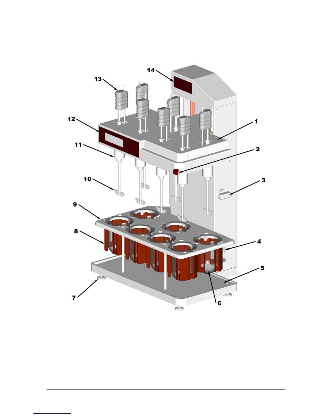
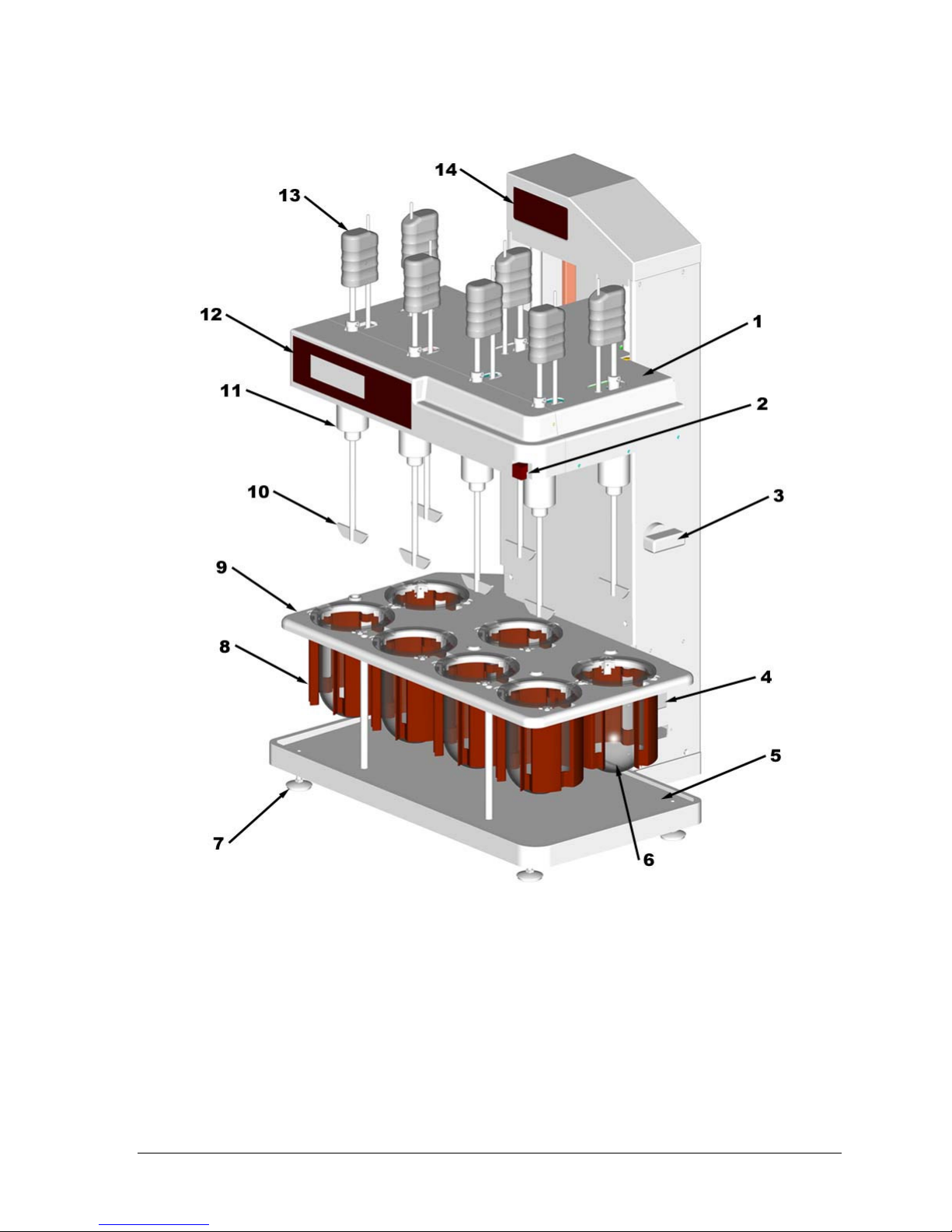
1. Drive Unit 6. Glass Vessel 11. Spindle Assembly
2. Brake Release 7. Leveling Feet 12. Front LCD Display
3. Height Adjustment Knob 8. Heater Assembly 13. Shaft Handle
4. Power Switch 9. Vessel Support Plate 14. Top LED Display
5. Base Plate 10. Paddle Blade
Operation Manual: Evolution Series
Figure 1-1: Distek Evolution 6100
Page 22

Chapter 2: Installation
2-1
2222 Installation
This chapter will describe the steps necessary to properly unpack and install the
instrument.
Unpacking ............................................................................. 2-2
Leveling the Evolution System ..................................................... 2-3
Installing the Thermocirculator (Evolution 6300 Only) ......................... 2-6
Placement and Connections ..................................................... 2-7
Filling the Water Bath ............................................................ 2-8
Priming the Pump ................................................................. 2-8
Positioning the Vessels ............................................................. 2-10
Paddle and Basket Installation ....................................................2-11
Paddle Blade Installation........................................................2-11
Basket Installation ............................................................... 2-11
Checking Paddles, Baskets and Shafts for Straightness.....................2-12
Checking Shaft Centering ....................................................... 2-12
Paddles and Basket Height Adjustment..........................................2-12
Initial Height Setting for Paddles and Baskets: .............................. 2-13
Quick Change Height Adjustment Knob (Paddles or Baskets).............. 2-14
Installing the Calibration Probe................................................... 2-14
Installation Checkout...............................................................2-15
RPM Control .......................................................................2-15
Test Duration ..................................................................... 2-15
Temperature Control ............................................................2-16
Time and Date ....................................................................2-16
Operation Manual: Evolution Series
Page 23

Chapter 2: Installation
2-2
Unpacking
Please take a few moments when unpacking the Distek Evolution Dissolution
Testing System to check for all items indicated on packing list. Notify Distek or
your shipper immediately of any discrepancies or damage to cartons or contents in
transit.
To avoid injury, two people should remove the
Evolution System from its carton.
Packing must be removed before operating this instrument. To remove packing:
1. Cut through the tape at the top of the carton. Open the four top flaps.
2. Carefully remove the packing inserts and lift the instrument from the
shipping carton. See warning and cautions above.
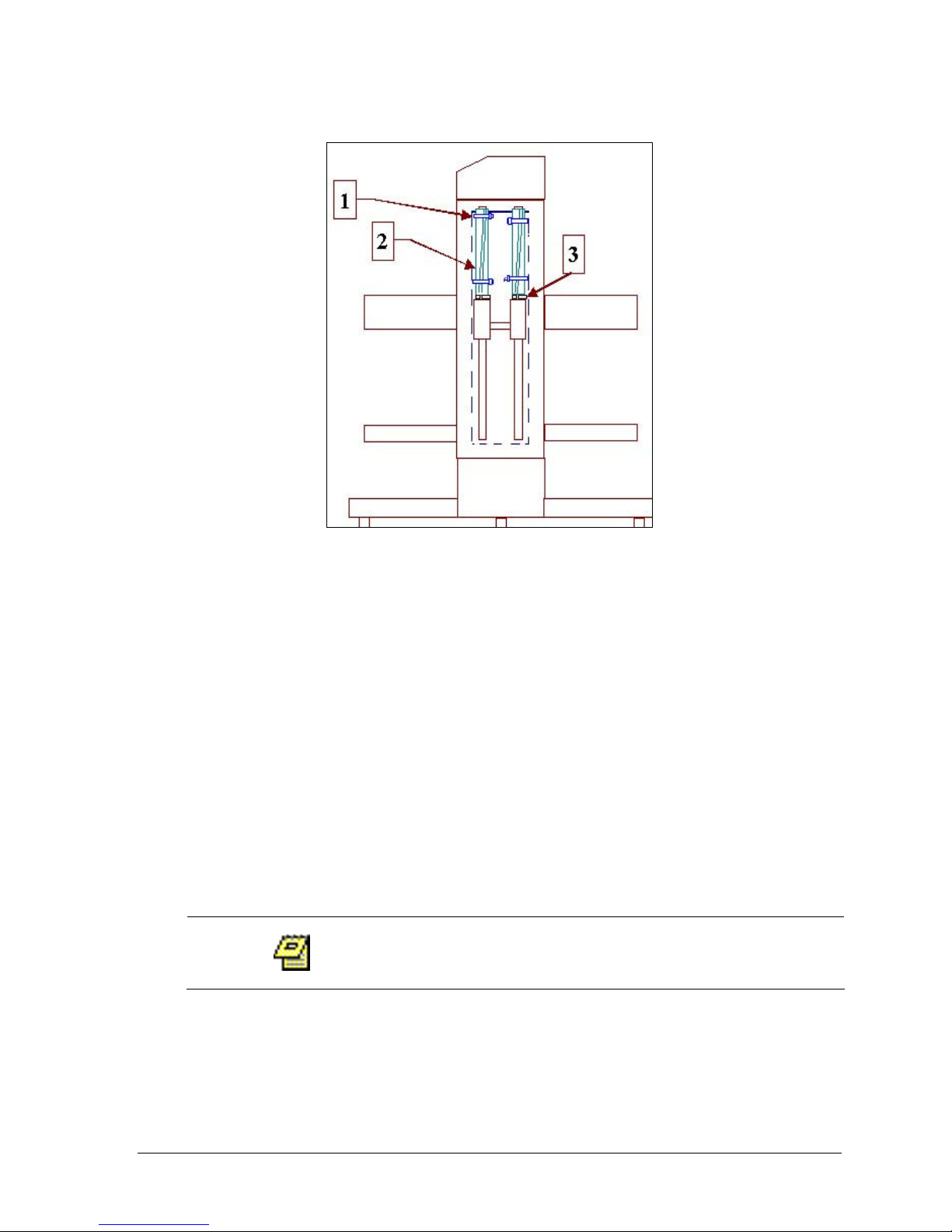
3. If the drive unit is locked in place, tie-wraps are visible from the front of
the unit, above the bearings (see Figure 2-1).
4. Identify and cut the tie-wraps on the guide rods above the bearings and
remove the split tubing (see Figure 2-1).
5. Remove the split washer (Figure 2-1) from the top of each bearing.
6. Press the brake release button (see Figure 2-3) and gently raise drive unit.
7. Remove shaft protection tubes.
8. Let go of the brake release button to set the drive unit at the desired
height.
9. The power cord is shipped in a separate carton from the main unit.
Connect the power cord supplied to the Evolution System below the power
switch (see Figure 2-3). Locate the proper outlet for the Evolution System.
See Appendix C for electrical power requirements.
Do not bump or disturb built-in paddle shafts as this
may affect shaft runout.
The drive unit is locked in place during shipping.
Operation Manual: Evolution Series
Page 24
Chapter 2: Installation
2-3
Figure 2-1: Rear View - Inside
Leveling the Evolution System
To level the unit on the bench:
1. Trained personnel should lift the unit onto the bench and slide it into
position.
2. Make certain the two stabilizers under the rear of the base are not touching
the bench.
3. Loosen locking nuts on the front leveling feet using the appropriate (1/2”)
wrench.
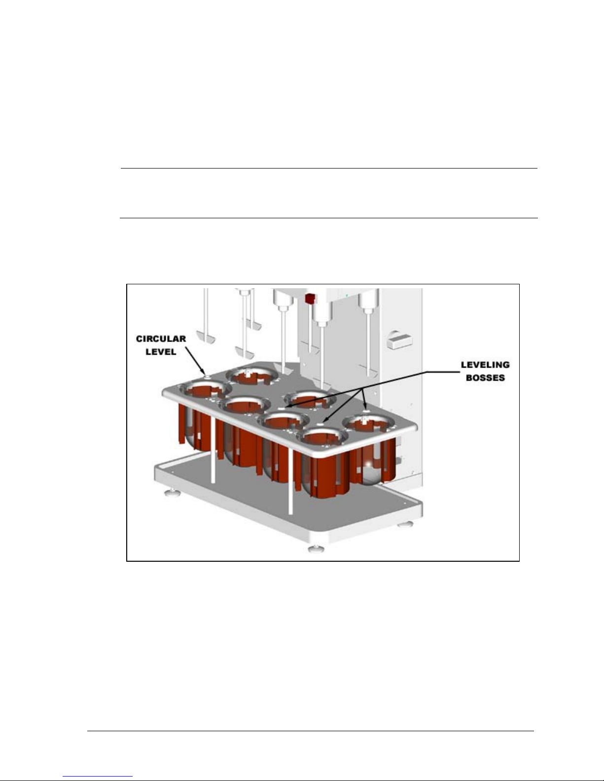
4. Observe the permanently mounted circular level on vessel support plate.
Level unit from front to back and side to side by adjusting the two front
leveling feet under the instrument base. See Figure 2-2.
5. Required Action: Tighten the locking nut on each foot at this time.
6. After leveling, adjust the two stabilizers under the rear of the instrument
base so that they just touch the bench.
7. Mark the location of the leveling feet on the bench to prevent changes in
level due to moving the unit. Check the level after completing installation,
Do not loosen the rear levelling foot. Level the
unit by adjusting the front levelling feet.
Operation Manual: Evolution Series
Page 25
Chapter 2: Installation
2-4
or after moving the Evolution System to a new location. Verify the accuracy
of the built-in circular level by placing a 6-9” carpenter’s level on the vessel
plate leveling bosses (see Figure 2-2). Check level from front to back and
side to side.
Connect this unit to the specified ac supply.
Observe proper grounding.
8. Plug the Evolution unit into the proper electrical outlet provided.
Figure 2-2: Leveling the Evolution System
Operation Manual: Evolution Series
Page 26
Chapter 2: Installation
2-5
1. Drive Unit 6. Glass Vessel 11. Spindle Assembly
2. Brake Release 7. Leveling Feet 12. Front LCD Display
3. Height Adjustment Knob 8. Heater Assembly 13. Shaft Handle
4. Power Switch 9. Vessel Support Plate 14. Top LED Display
5. Base Plate 10. Paddle Blade
Operation Manual: Evolution Series
Figure 2-3: Evolution Dissolution System
Page 27
Chapter 2: Installation
2-6
Installing the Thermocirculator (Evolution 6300 Only)
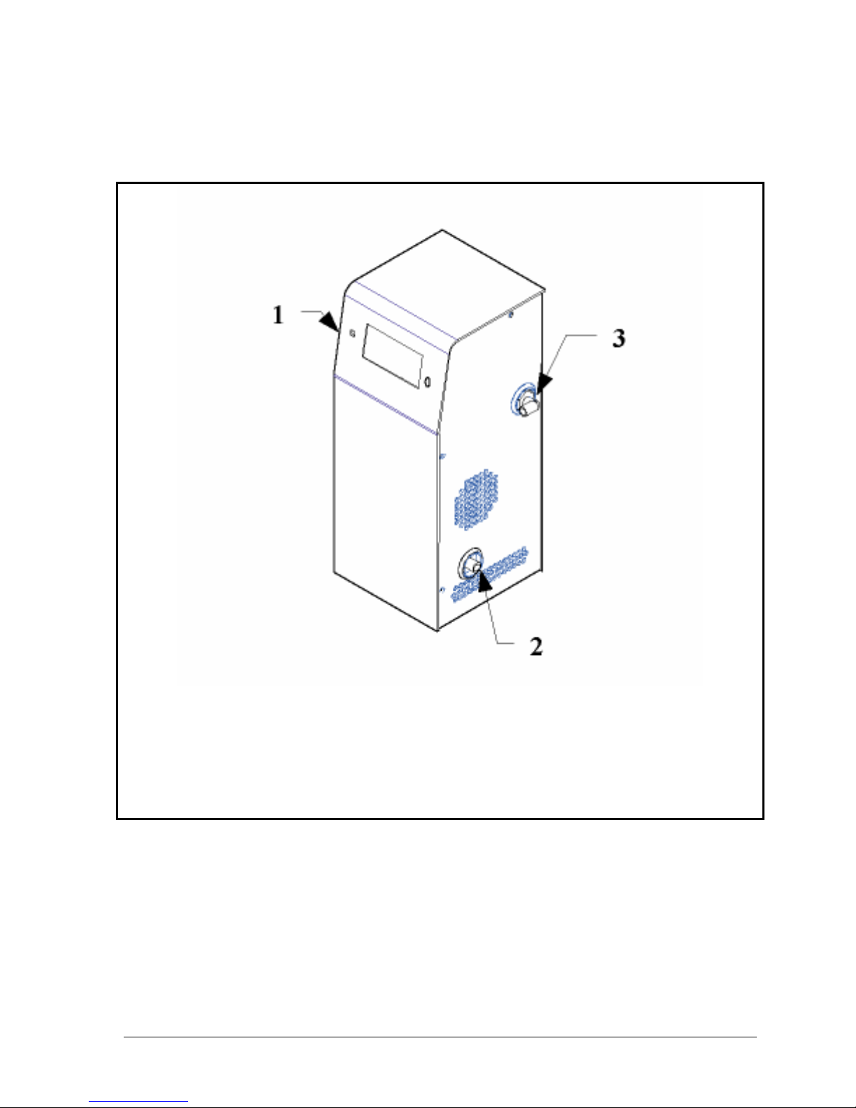
Figure 2-4: Model TCS-0200C Thermocirculator
1. Thermocirculator Housing
2. Pump Inlet
3. Pump Outlet
Operation Manual: Evolution Series
Page 28

Chapter 2: Installation
2-7
Figure 2-5: Thermocirculator Connections
Placement and Connections
1. Install the TCS-0200C behind the right side of the Evolution bath.
2. Place TCS-0200C Thermocirculator on bench and at the same level as
Evolution, or below.
Thermocirculator TCS-0200C is normally placed on same
level as Evolution bath, or below, in order for pump to
be primed properly. Contact Distek for special
instructions if pump needs to be installed higher than
bath. Failure to install and prime the Thermocirculator
as specified may result in damage to heater and/or
pump, and void the warranty.
3. Make sure ventilation holes on both sides of TCS-0200C are not obstructed.
4. Connect power cord to back of TCS unit.
5. Place a hose clamp loosely on inlet and outlet hoses.
6. Connect the water bath inlet hose (1/2" I.D.) to the pump outlet as shown
in Figure 2-5 (upper connection on the bath and pump).
Operation Manual: Evolution Series
Page 29

Chapter 2: Installation
2-8
7. Connect water bath outlet hose (5/8” I.D.) to the pump inlet using quick
disconnect coupling (lower connection on the bath and pump). Push the
coupling together until it clicks.
8. Make sure all hoses are installed fully onto fittings.
9. Place the hose clamps over fittings, with locking portion on right side of
fitting.
10. Tighten hose clamps snugly with pliers. Adjust position of unit so TCS does
not touch the Evolution bath, to avoid transmitting vibration.
Filling the Water Bath
1. Wipe the inside of water bath with damp cloth to remove any debris that
might lodge inside and damage pump.
2. Make sure the power switch on the upper rear panel of TCS-0200C is off
(press "0"). Plug the TCS into proper outlet.
3. Place temperature probe from TCS-0200C in bath location next to center
rear vessel.
4. Make sure bath drain valve is closed (handle should be perpendicular to
drain hose as shown in Figure 2-5).
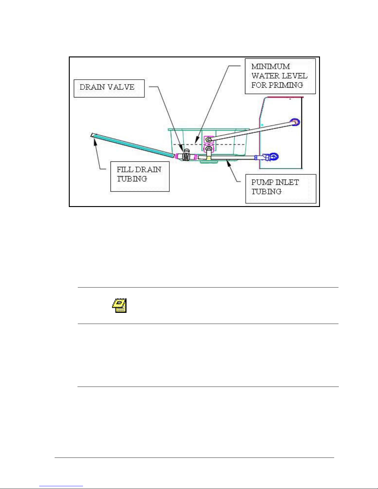
5. Fill bath to midway between the top bath inlet fitting and the lower outlet
fitting (see Figure 2-7).
Priming the Pump
1. Attach a 3 ft. ( 1m) long x 5/8" (~16mm) ID drain tubing to drain valve.
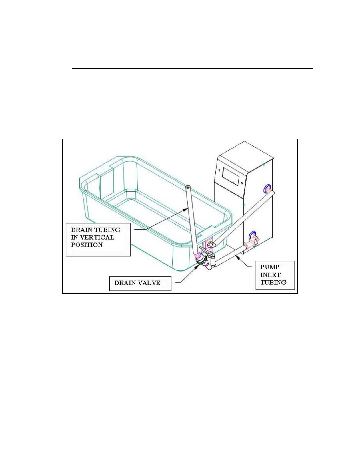
2. Raise drain tubing: Raise the drain tubing to vertical position as shown in
Figure 2-6. Drain valve should be tilted up.
3. Open drain valve. Allow pump inlet tubing to fill with water (5-10 sec.).
4. See Figure 2-7 below. While trying not to spill, slowly lower drain tubing to
allow tubing to fill with water as shown. Fill as much as possible.
5. Close drain valve.
6. Again lift drain tubing to vertical position (see Figure 2-6 above).
7. While holding drain tubing vertical, open drain valve for 5 seconds.
8. Repeat above steps #4 (SLOWLY lower drain tubing …) through #7.
9. Close drain valve.
10. With valve closed dispense residual water from drain tubing into a bucket.
11. Turn on TCS power and run TCS for 15 seconds. (Power switch is on upper
rear panel of TCS.) If priming is successful, water should flow rapidly from
bath inlet within 15 seconds. If not, turn off TCS immediately and go back
to step #7, "Raise Drain Tubing".
12. Re-check the instrument level again (see Figure 2-2) with water in the bath.
Adjust leveling feet if necessary.
13. Tighten the locking nuts on each leveling foot.
14. Check all fittings for leaks for next five minutes.
Operation Manual: Evolution Series
Page 30
Chapter 2: Installation
2-9
15. Momentarily turn pump on to verify that pump is primed and flow is steady.
DO NOT RUN PUMP WHEN DRY. If pump is not
16. If water in bath is not circulating, stop the pump. Go back to "Raise Drain
Tubing".
17. When flow is steady, turn on TCS-0200C and set the temperature (see page
3-33).
primed properly, internal thermal safety switch
will trip.
Operation Manual: Evolution Series
Figure 2-6: Drain Tubing in Vertical Position
Page 31
2-10
Figure 2-7: Drain Tubing Filled with Water
Chapter 2: Installation
Positioning the Vessels
To install vessels in vessel plate:
1. Raise the drive unit.
2. Insert a vessel in each position on the vessel plate.
3. Slide vessel through vessel clips until it can go no further.
The top of at least one vessel clip should contact
the bottom of the vessel flange.
Distek supplies highly uniform vessels that fit properly
into the 6100 heater assemblies. Use of vessels other
than those supplied by Distek for the 6100 may result
in unsatisfactory operation or heater damage and void
the warranty.
Operation Manual: Evolution Series
Page 32

Chapter 2: Installation
2-11
Paddle and Basket Installation
Paddle Blade Installation
1. Carefully screw a paddle blade onto bottom of each shaft. Assemble fingertight.
Basket Installation
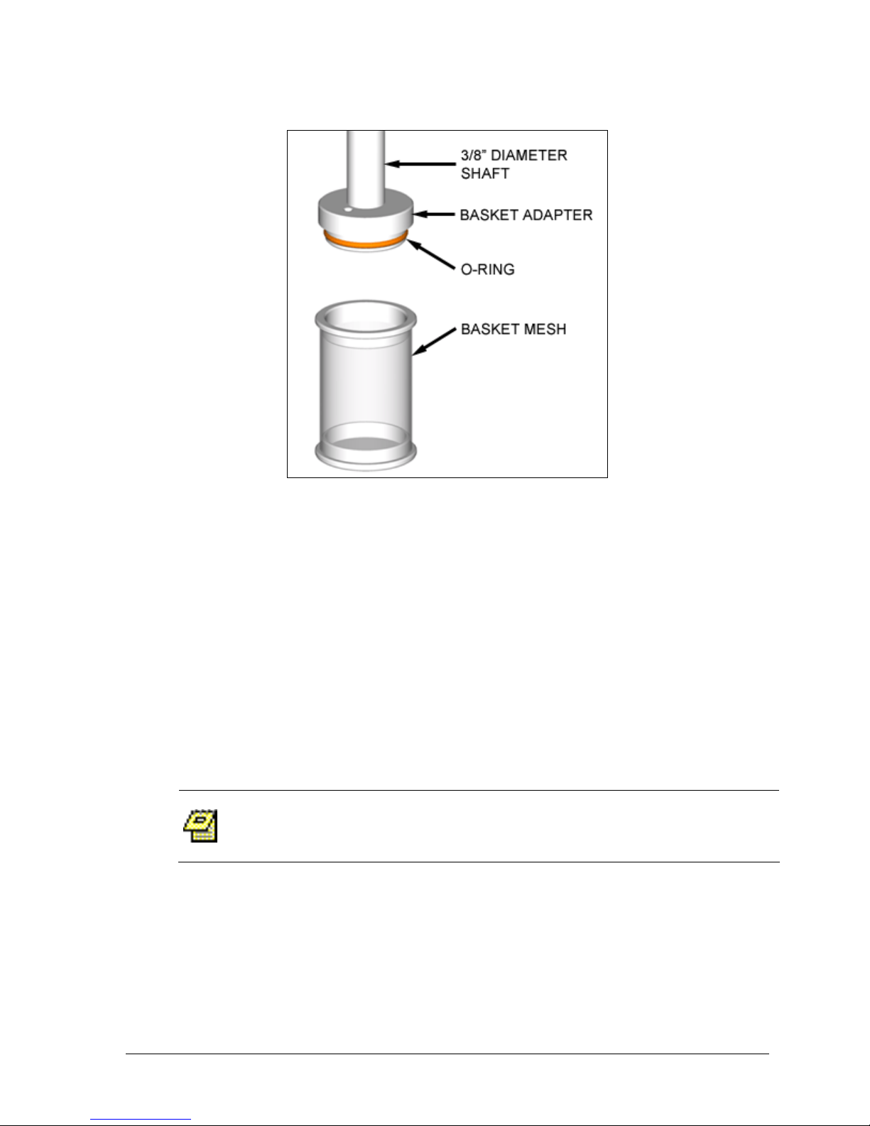
1. Carefully screw a basket adapter onto the bottom of each shaft. Assemble
finger-tight. (See Figure 2-8).
2. Vessel pre-heat may be performed at a higher RPM depending on test
parameters. Baskets are not installed during pre-heat.
3. Always place a tablet or capsule into a dry, empty basket before the test.
4. When the vessel stabilizes at test temperature, lift the shaft out of the vessel.
5. Place the basket, open end up, in palm with thumb and fingers grasping
knurled grip. (See Caution above.)
6. Raise basket until inside of the upper ring just contacts the O-ring shown in
Figure 2-8.
7. Twist and push the basket onto the adapter.
8. When removing the basket, grasp only on the knurled grip. Pull down and
twist.
Do not grasp basket by mesh screen when installing
or removing. ALWAYS GRASP BASKETS BY UPPER
RIM. Proper handling will prevent basket distortion
and RESULTING wobble.
Upon completion of each test, rinse baskets and
shafts thoroughly with distilled water. DO NOT
ALLOW ACIDS OR BUFFERS TO DRY ON THE METAL
SURFACES.
Operation Manual: Evolution Series
Handle paddle blades and optional baskets carefully to
avoid bending or damage. Store carefully in original
container to prevent damage.
Page 33
2-12
Figure 2-8: Installing Basket on Shaft
Chapter 2: Installation
Checking Paddles, Baskets and Shafts for Straightness
Use instruments such as Distek’s Wobble Meter, ShaftChek, or other means to
verify straightness of stirring shafts, blades and baskets. Check shaft wobble near
bottom end of shaft. Check basket wobble at bottom rim of basket. Record
values at 25 and 250 RPM.
Checking Shaft Centering
Use Distek CenterChek or other means to verify shaft centering with respect to
vessels. Follow instructions included with CenterChek for accurate results.
“Basket” refers to USP Dissolution Apparatus 1.
“Paddle” refers to USP Dissolution Apparatus 2.
Paddles and Basket Height Adjustment
The paddle and basket height is configured at Distek's factory and should not have
to be changed unless the height is out of calibration. The following procedure
describes how to properly adjust the height setting. This procedure should only be
Operation Manual: Evolution Series
Page 34

Chapter 2: Installation
2-13
used to set the initial height. Once the unit's height is calibrated the Quick
Change Height Adjustment Knob (Paddles or Baskets) procedure should be
followed to switch between paddles and baskets.
Initial Height Setting for Paddles and Baskets:
1. Press brake release button and raise drive unit.
2. Turn height adjustment knob (see Figure 2-9) to either horizontal position.
3. Loosen shaft locking collars so they slide freely on shafts. Use 7/64” Allen
(hex) wrench.
4. Raise shafts slightly by pulling up on protective covers (gray handles).
5. IMPORTANT: Install paddle blades on all shafts, even if baskets will be used
for testing. Paddle blades must be used to set shaft collars!
6. Lower drive unit slowly to lowest position so drive plate extension rests on
height adjustment knob.
7. While applying slight downward pressure on drive unit, let go of brake
release button to lock drive unit in place. Make sure drive plate extension
touches height adjustment knob.
8. Lower shaft gently until paddle blades touch the bottom of each vessel.
9. Lock each shaft collar using 7/64” Allen wrench.
10. Raise the drive unit approximately six inches.
11. Turn the height adjustment knob to “PADDLES” position as seen from the
front of the unit (see Figure 2-9).
12. Lower drive unit gently until it comes to rest on height adjustment knob and
release brake button.
13. Check paddle or basket height using Distek HeightChek or other means.
Verify and record distance from bottom of each paddle or basket to bottom
of vessel. (Do not change the position of the shaft collars.)
14. To switch to baskets, raise the drive unit and install baskets on the shafts.
15. Turn the knob to "BASKETS" position (see Figure 2-9).
16. Lower drive unit gently until it comes to rest on height knob and release
brake button.
17. Check paddle or basket height using Distek HeightChek or other means.
Verify and record distance from bottom of each paddle or basket to bottom
of vessel.
If shafts do not slide up smoothly, a very thin film of
lubricant may be applied to shaft, only to area just
below spindle. Wipe off any excess grease. Move shaft
up and down gently to distribute lubricant. If
necessary, Distek recommends Dow Corning High
Vacuum Grease. Do not use a lubricant which may
affect your test results.
Operation Manual: Evolution Series
Page 35
Chapter 2: Installation
2-14
Quick Change Height Adjustment Knob (Paddles or Baskets)
After completing the previous setup procedure (if applicable), it should not be
necessary to move the shaft collars when switching back and forth from baskets to
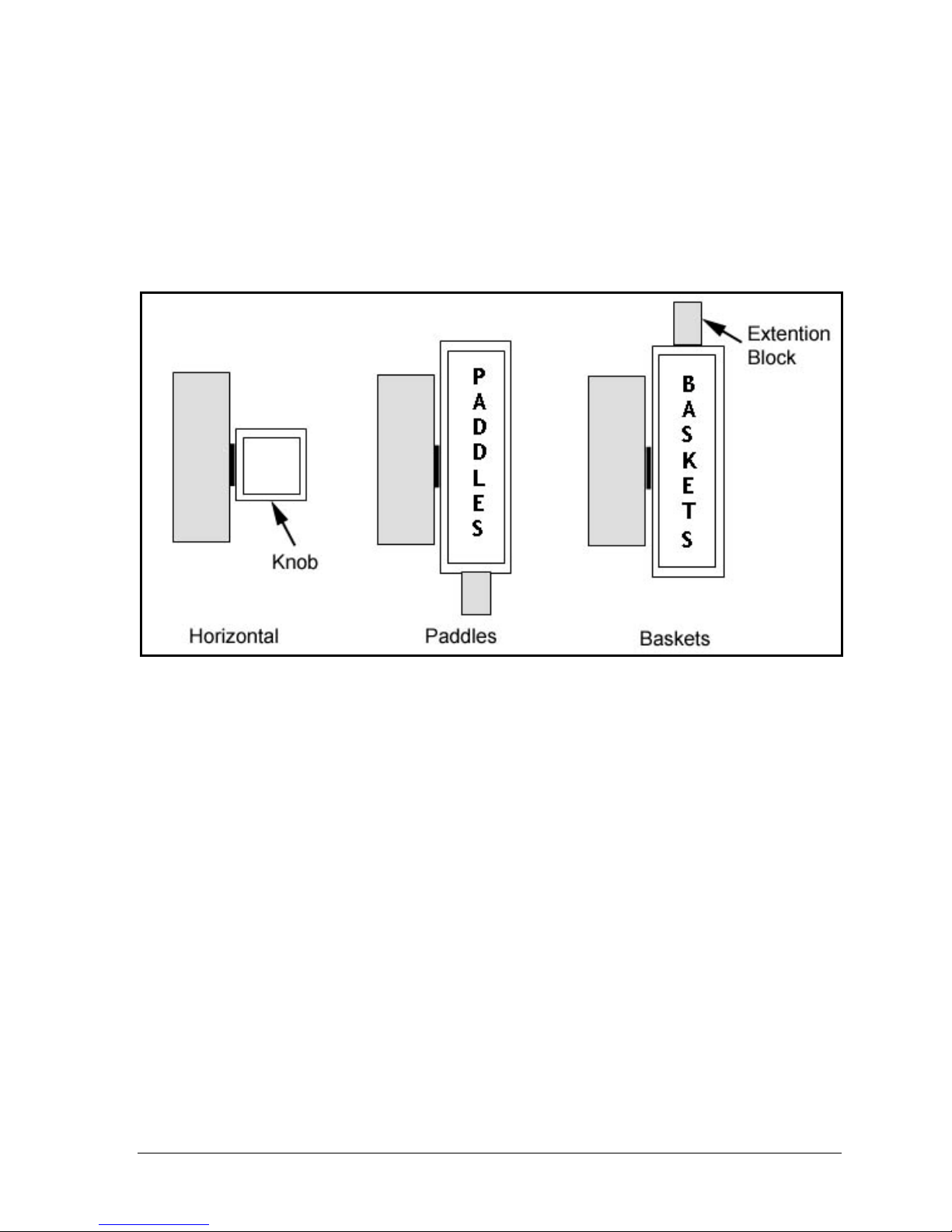
paddles. Simply rotate the height adjustment knob as shown in Figure 2-9. The
extension block compensates for the difference in height paddles and baskets.
Figure 2-9: Quick Height Change Diagram
Installing the Calibration Probe
1. Make sure the serial number of the hand-held calibration probe matches the
serial number of the 6100/6300.
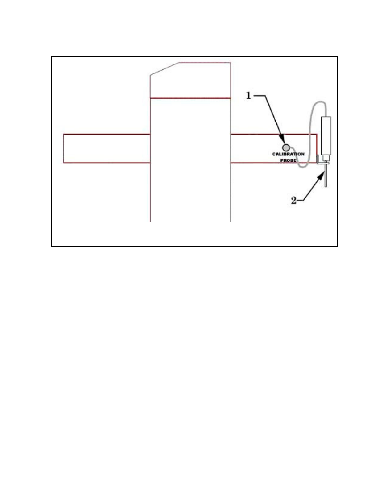
2. Plug in the calibration probe at the rear of the unit.
3. Place probe in holder (see Figure 2-10).
Operation Manual: Evolution Series
Page 36
Chapter 2: Installation
2-15
Figure 2-10: Drive Unit (Rear View)
1. Calibration Probe Port 2. Holder with Probe
Installation Checkout
Your instrument has been tested thoroughly before shipment. To detect any
problems caused by shipping and handling, Distek recommends a careful check of
all crucial operating parameters after complete installation of the dissolution
system.
RPM Control
Check and record RPM display accuracy at 50, 100, 150 and 250 RPM using a
calibrated tachometer such as Distek RPMChek.
Test Duration
Check and record timing accuracy at test RPM using a calibrated stopwatch. Test
should be run over a range of expected usage. For example, if test durations and
sample times range from 15 minutes to 12 hours, testing should measure intervals
of 10 minutes, 1 hour, and 24 hours.
Operation Manual: Evolution Series
Page 37

Chapter 2: Installation
2-16
Temperature Control
1. Install paddle blades.
2. Raise drive assembly.
3. Fill each vessel with 900ml of DI water at 18-22°C.
4. Turn height adjust knob to “Paddles” position.
5. Lower drive assembly and paddles fully.
6. Cover all vessels with vessel covers provided.
7. Place a calibrated reference temperature probe, such as Distek TempChek, in
one of front center vessels.
8. Record vessel temperature and time.
9. Set rotation to 150RPM (see Controlling All Vessels on page 3-32).
10. Set operating temperature.
11. Highlight START HT/STIR button and press ENTER.
12. Monitor temperature and time until vessel temperature stabilizes.
13. Adjust temperature set-point so that vessel temperature stabilizes at required
vessel temperature (such as 37.0°C).
14. Record set-point required to achieve required vessel temperature.
15. Verify & record temperature calibration of calibration probe and each vessel
probe using external reference thermometer at approximately 37°C.
Time and Date
Verify that the system time and date are correct.
1. From the Main screen select SYSTEM SETUP.
2. Select SYSTEM CONFIG.
3. Verify that the time and date parameters are correct.
4. Make changes if necessary.
Operation Manual: Evolution Series
Page 38

Chapter 3: Operation
3-1
3333 Operation
The chapter will describe the user interface screens and system administration for
the instrument. It will also provide step-by-step instructions to perform many of
the instrument’s common tasks.
Operation Manual user interface screen shots may vary
Control Keypad ....................................................................... 3-4
ESC/DEL Button.................................................................... 3-4
RUN/STOP Button ................................................................. 3-4
Arrow Keys ......................................................................... 3-4
ENTER Button ...................................................................... 3-4
+ Button ............................................................................ 3-5
- Button ............................................................................. 3-5
Stir LED ............................................................................. 3-5
Heat LED............................................................................ 3-5
Sleep LED ........................................................................... 3-5
produKEY ........................................................................... 3-5
Startup Screens....................................................................... 3-5
System Administration .............................................................. 3-6
System Setup....................................................................... 3-7
Advanced Options .............................................................. 3-8
from actual instrument interface screens.
Operation Manual: Evolution Series
Page 39

Chapter 3: Operation
3-2
Unit Address ..................................................................... 3-8
TCS Address (Evolution 6300 Only)........................................... 3-9
Preheat (Evolution 6300 Only) ................................................ 3-9
Temperature Control (Evolution 6300 Only)............................... 3-10
Beep Mode ...................................................................... 3-10
Height Switch Setting ......................................................... 3-10
Printer Sharing Configuration (Evolution 6100 Only) ..................... 3-11
About Window.................................................................. 3-12
User Configuration ............................................................... 3-12
Login Procedures .............................................................. 3-13
Creating a New Account ...................................................... 3-14
Changing the Privileges of an Existing Account ........................... 3-15
Changing a Password .......................................................... 3-15
Deleting an Account........................................................... 3-16
Temperature Calibration........................................................3-16
Calibrate Using Evolution Calibration Probe............................... 3-18
Calibrate Using TempChek Digital Thermometer ......................... 3-19
Calibrate Using NIST-Traceable Reference Thermometer ............... 3-19
Calibrate calPROBE Using TempChek Digital Thermometer ............. 3-20
Calibrate calPROBE Using NIST-Traceable Reference Thermometer... 3-21
Display Screens ......................................................................3-21
Temperature Screen ............................................................. 3-21
Temperature and RPM Screen .................................................. 3-22
Current Method...................................................................3-23
Report History .................................................................... 3-23
Printing a Saved Report .........................................................3-24
Working with Methods (Automatic Mode) .......................................3-24
Selecting a Method to Run ...................................................... 3-24
Sorting the Method List..........................................................3-25
Programming a New Method ....................................................3-25
Running a Simultaneous Drop with Paddles .................................. 3-27
Running a Simultaneous Drop with Baskets...................................3-28
Running a Staggered Drop with Paddles ...................................... 3-28
Running a Staggered Drop with Baskets....................................... 3-28
Open/View an Existing Method.................................................3-29
Modify a Saved Method ..........................................................3-30
Deleting a Method................................................................ 3-30
Copy a Saved Method to a New Name......................................... 3-30
Printing Method Parameters .................................................... 3-31
Working in Manual Mode ...........................................................3-31
Controlling Vessels Individually (Evolution 6100 Only) ..................... 3-32
Controlling All Vessels ...........................................................3-33
TCS Activation (Evolution 6300 Only) .........................................3-35
Running a Manual Mode Test ...................................................3-35
Using the produKEY ................................................................. 3-36
Operation Manual: Evolution Series
Page 40

Chapter 3: Operation
3-3
Saving a Method to the produKEY..............................................3-36
Viewing Methods on the produKEY............................................. 3-37
Saving a Method from the produKEY to the Instrument ....................3-37
Running a Method from the produKEY ........................................ 3-37
Deleting Methods from the produKEY .........................................3-38
Printing a Method from the produKEY.........................................3-38
Using a Premiere 5100 produKEY .............................................. 3-38
Using the calKEY ....................................................................3-38
Storing Calibration Data.........................................................3-39
Restoring Calibration Data ......................................................3-39
Printouts.............................................................................. 3-40
Serial Port Control ..................................................................3-40
Operation Manual: Evolution Series
Page 41
3-4
Control Keypad
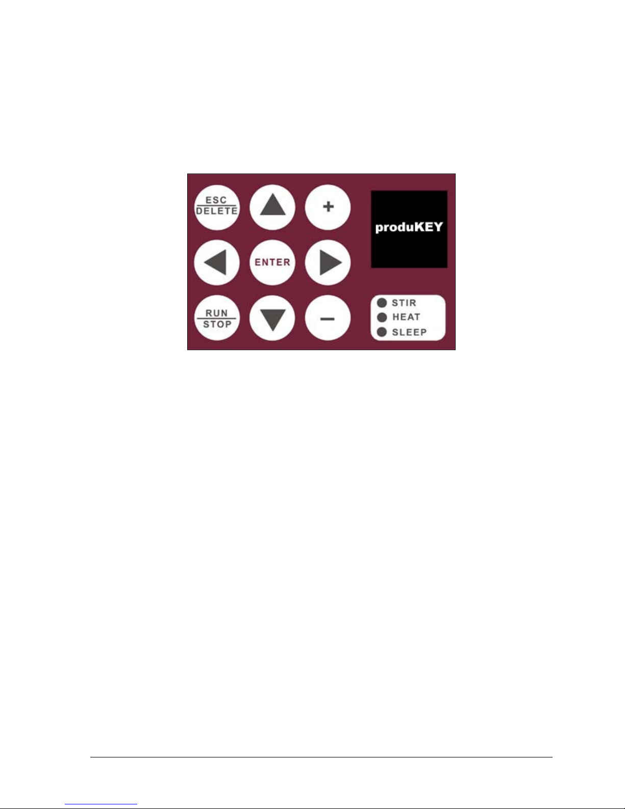
The control keypad is shown in Figure 3-1:
Chapter 3: Operation
Figure 3-1: Control Keypad
The function of the buttons is as follows:
ESC/DEL Button
The ESC/DEL button will allow the operator to navigate back to the higher level
menu screen within the interface. This button can also be used to delete certain
items that are in a list such as methods, sample time points and users.
RUN/STOP Button
The RUN/STOP button is used to start a method running while in the method
screen. If a method is already running, this button can be used to abort a method.
Arrow Keys
The ARROW keys are used to navigate through the menus and displays.
ENTER Button
The ENTER button locks in menu selections and settings made with the ARROW, +
and – keys.
Operation Manual: Evolution Series
Page 42
Chapter 3: Operation
3-5
+ Button
The + button will toggle through available options depending on what field is
selected. For example, when modifying the test temperature in a saved method
these buttons will scroll through numeric values.
- Button
The – button works in conjunction with the + button to scroll in the opposite
direction.
Stir LED
This LED will be activated when the instrument shafts are rotating at a set RPM.
Heat LED
This LED will be activated when the heaters are active (heater jackets for the
bathless model or the TCS for the bath based system).
Sleep LED
This LED will be activated when the unit is set to sleep mode. Sleep mode turns
off the display in order to extend the life of the unit’s backlight.
produKEY
This receptacle is used with the produKEY. See page 3-36 for more information on
using the produKEY.
Startup Screens
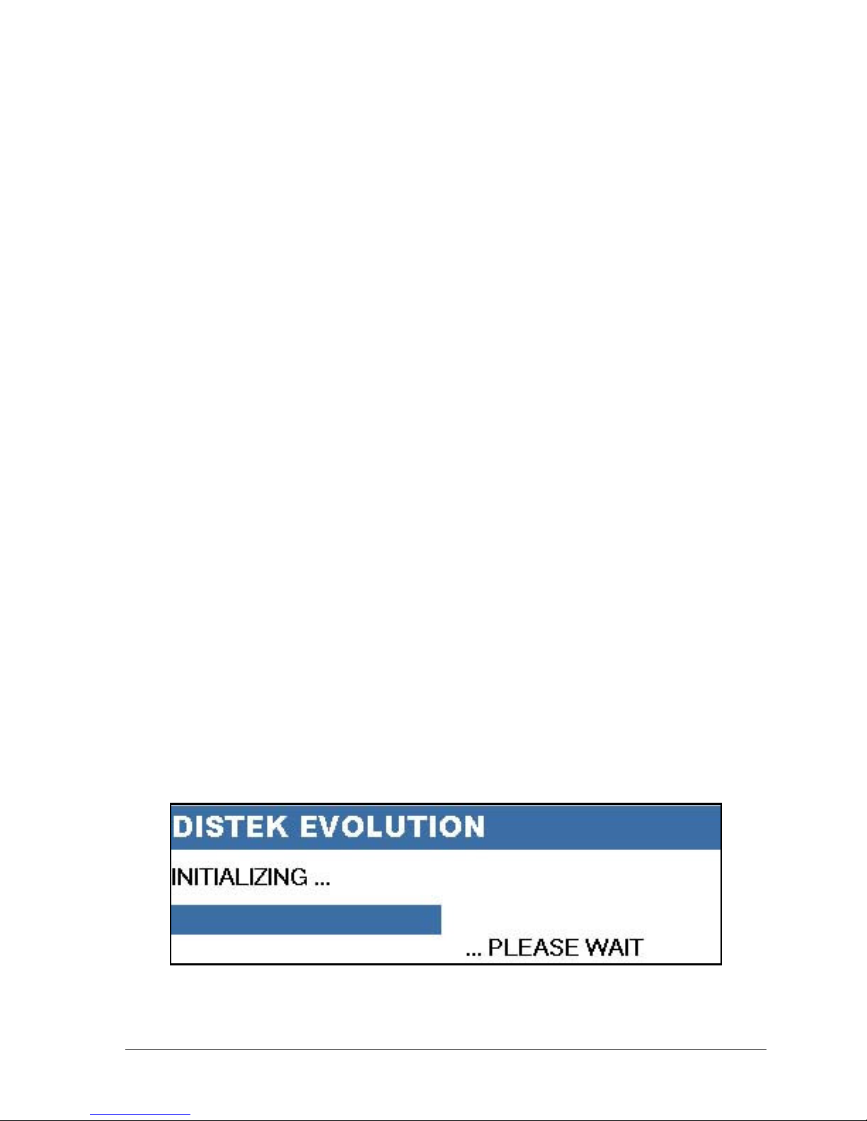
The following initialization screen will appear on the front LCD when turning the
unit on:
Operation Manual: Evolution Series
Figure 3-2: Initialization Screen
Page 43
Chapter 3: Operation
3-6
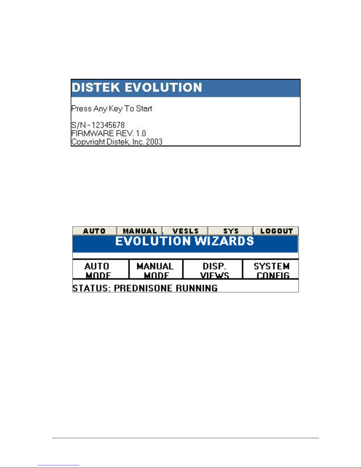
This screen will disappear when the system has booted up and the following screen
will be displayed:
Figure 3-3: Welcome Screen
The serial number and firmware revision is displayed along with a message: “PRESS
ANY KEY TO START…” The system will proceed to the login screen after a key is
pressed or will automatically go to the login screen after about 10 seconds (see
Login Procedures on page 3-13).
After logging in to the system the Main menu will be displayed:
Figure 3-4: Main Screen
The menu bar at the top of the screen contains 5 buttons used to navigate through
the system. This format is consistent throughout the interface.
System Administration
The system section (“SYS” on the menu bar) of the unit allows access to system
setup, USER/MANAGER administration and calibration of the instrument.
Operation Manual: Evolution Series
Page 44
Chapter 3: Operation
3-7
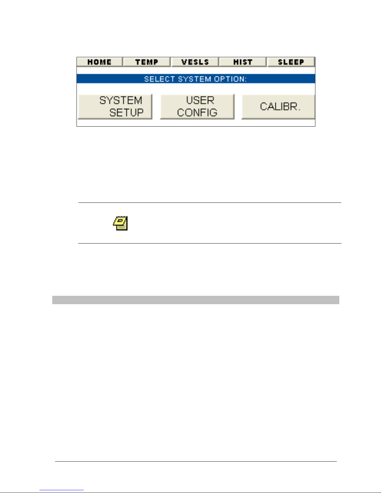
Figure 3-5: System Administration Wizard
The Evolution System is equipped with login access to allow for USER and
MANAGER group settings. A USER can only view and select a method to run. A
MANAGER is able to create/modify methods, change system configuration settings,
calibrate the unit and has user administration privileges.
System Setup
Only a MANAGER will be able to modify the setting
found in the system administration section. A
USER will only be able to view these settings.
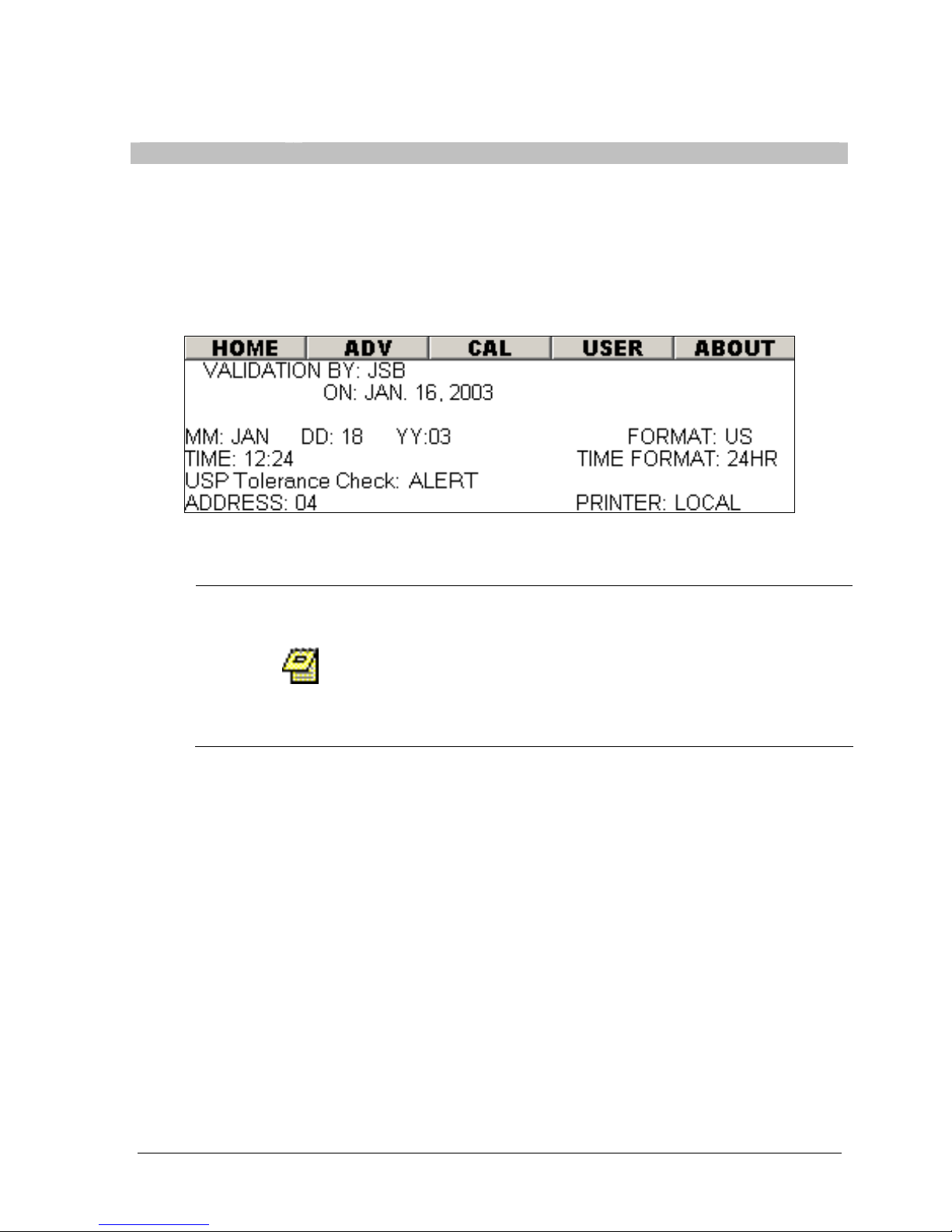
Upon selecting the “SYSTEM SETUP” button on the system administration wizard
the user will be taken to the screen shown in Figure 3-6.
The following settings are listed on this screen:
Setting Description
Validated By: The name of the person who validated the unit. This can be up
to 8 characters.
Date: The date the unit was last validated.
MM:DD:YY: Current date.
Format: The date can be set to US or EURO format. For example:
US: Jan.16, 2003
EURO: 16 Jan. 2003
Time: Current time.
Time Format: The time can be set to AMPM or 24HR.
USP Tolerance
Check:
This option monitors the temperature and RPM range when
running a method. The valid settings are ALERT, ABORT or
OFF. If either of these 2 parameters go outside the USP limit
the system will either ALERT the user but continue running,
ABORT the method or not monitor these parameters if set to
OFF.
Address: This is the unit address which can be used for external control.
Operation Manual: Evolution Series
Page 45
3-8
Setting Description
Printer
(Evolution 6100
Only):
The printer settings are L or XX. 'L' should be used when a
printer is connected directly to the unit (local printing). 'XX'
represents the unit address for remote printing (printer
sharing). See Printer Sharing Configuration on page 3-11 for
more information.
Figure 3-6: System Setup Screen
Chapter 3: Operation
Advanced Options
When selecting the ADV button the unit will prompt the
use for a password. The password is 'EVOADV' and only
will be accepted if the user logged in to the system has
Manager priveleges. Because these option are not
frequently used and can cause system errors, this added
level of security was implemented.
The system setup screen contains a menu entitled “ADV”. The settings for
Validation By, Validation Date, Unit Address and TCS address (Evolution 6300
only), Beep and Height Switch can only be modified in the ADV screen. When a
user selects this option the system will prompt the user to enter a password. This
ensures that these critical parameters are not easily modified.
Unit Address
The following procedure describes the steps necessary to change the unit address:
1. From the 'SYS CONFIG' screen select the 'ADV' menu.
2. Enter the password for this screen.
3. Highlight the ADDRESS field.
4. Using the + and – button set to the desired address.
Operation Manual: Evolution Series
Page 46

Chapter 3: Operation
3-9
TCS Address (Evolution 6300 Only)
Distek instruments that are connected to the unit
(i.e. 4300, 6300, etc.) must be turned off or
disconnected (remove communication cables)
temporarily while changing the address. This
avoids inadvertently changing the addresses of the
other connected instruments.
For the Evolution 6300 it is necessary to establish communications with the TCS.
The screen shown in Figure 3-6 will contain a field for 'TCS'. This represents the
TCS address. This option is only selectable via the 'ADV' screen.
To establish communication for the first time or the change the TCS address,
follow the procedure below:
1. Disconnect any Distek instrument that is currently connected to this unit
(i.e. 4300, 6300, etc.) by removing the RS-485 cable. (Do not remove the
RS-485 going from the main unit to the TCS, only remove the cable going
from this unit to the external devices.)
2. From the 'SYS CONFIG' screen select the 'ADV' menu.
3. Enter the password for this screen.
4. Highlight the TCS address field.
5. Using the + and – button set to the desired address.
6. Press ENTER.
7. A warning message will be displayed. Select 'YES' to accept the change.
8. Exit out of the ADV screen for the change to take affect.
Preheat (Evolution 6300 Only)
During preheat the unit will display the temperature ready screen only when it
determines that the vessel temperatures are stable. In order to verify the unit’s
stability the system checks each vessel repeatedly during preheat. Each vessel
must meet the following criteria during a two minute period in order for the test
to begin:
Test Temperature ± Preheat Range
The preheat setting allows the user to set the Temperature Range from 0.2-0.5ºC.
The default value is 0.2ºC.
For example, if the test temperature is 37.0ºC and the preheat setting is 0.2ºC the
temperature ready screen will not be displayed until all vessels are in the range
37.0 ± 0.2ºC for two minutes. If one vessel falls outside the criteria the two
minute clock will be reset.
Operation Manual: Evolution Series
Page 47

Chapter 3: Operation
3-10
In general, a larger preheat value will allow for a faster preheat time, but might
not provide as much temperature stability as a lower setting.
Temperature Control (Evolution 6300 Only)
The Evolution 6300 has three modes of temperature control:
• Shafts: This is the default setting. In this mode the temperature is
controlled by the embedded sensor in the RTD shafts. This is the
recommended mode of operation unless mini-vessels are used.
• TCS: The temperature will be controlled by the TCS (not the RTD shafts).
The calPROBE must be placed into the water bath. The bath temperature
will be controlled by the TCS and the feedback of the bath temperature
from the calPROBE. Individual vessel temperature will still be reported;
however, the control of temperature will be handled by the TCS.
• Mini: This setting is for mini-vessels. The RTD shafts will be disabled and
only the bath temperature (using the calPROBE) will be reported. The
calPROBE must be placed into the water bath. The bath temperature will
be controlled by the TCS and the feedback of the bath temperature from
the calPROBE. The minimum vessel volume when creating methods will be
adjusted to accommodate smaller volumes. All references to individual
vessel temperatures will be removed from the user interface and reports.
Beep Mode
Disabling Beep mode eliminates audible operator prompts from unit, but still
provides verification beep whenever any key is pressed. To disable this option set
Beep to 'OFF'.
Height Switch Setting
Disabling the height switch causes the system to ignore the height sensor for the
drive head. This allows the shafts to continue stirring when the drive head is
raised. This feature is particularly useful for measuring basket wobble during
mechanical validation of the unit.
To disable the height switch turn the setting to 'OFF'.
The height sensor is an important feature of the
unit and should be turned back on as soon as the
validation has been completed.
Operation Manual: Evolution Series
Page 48
Chapter 3: Operation
3-11
Bath
less
4
Printer
Bath
less
1
Bath
less
2
Bath
less
3
Evolution
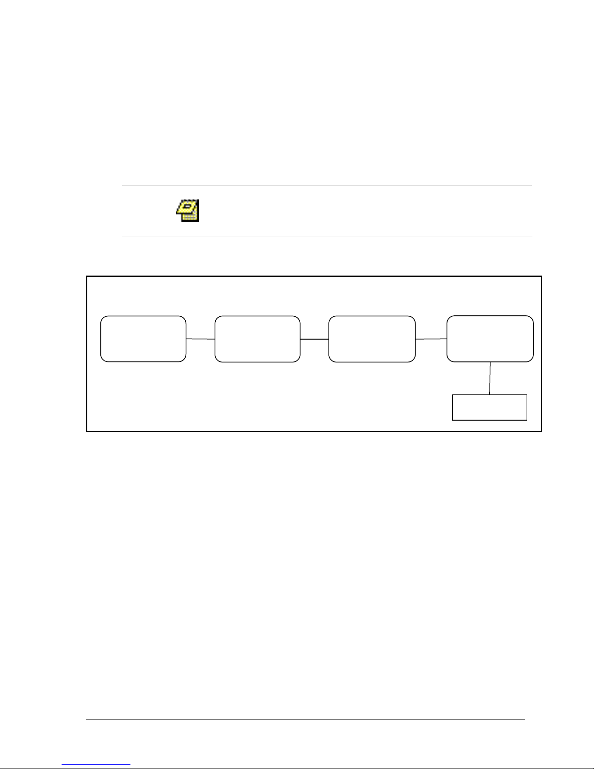
6100 Printer Sharing Diagram
Printer
Cable
Printer Sharing Configuration (Evolution 6100 Only)
The Evolution 6100 is equipped to have up to four units share one printer. This
option is configured by the printer setting located on the Advanced Option screen
in System Setup (see Figure 3-6).
The operator logged into the system must be part
of the Manager group to create a new user.
1. All units must be connected via an RS-485 cable. See diagram below.
(Unit Address 01
Printer 04)
RS-485
(Unit Address 02
Printer 04)
RS-485
(Unit Address 03
Printer 04)
RS-485
(Unit Address 04
Printer L)
2. Highlight the SYS. menu or SYSTEM CONFIG button from the Main screen and
press ENTER (see Figure 3-4).
3. Highlight the SYSTEM SETUP button and press ENTER (see Figure 3-11).
4. Highlight the ADV menu and press ENTER.
5. Highlight the PRINTER field and using the + and – keys scroll to the desired
value representing the address of the system which is directly connected to
the printer. Select 'L' if the printer is directly connected to the unit. For
example in the diagram above, Bath 1 will be set to 04, Bath 2 will be 04,
Bath 3 will be 04 and Bath 4 will be L.
Operation Manual: Evolution Series
Page 49
Chapter 3: Operation
3-12
About Window
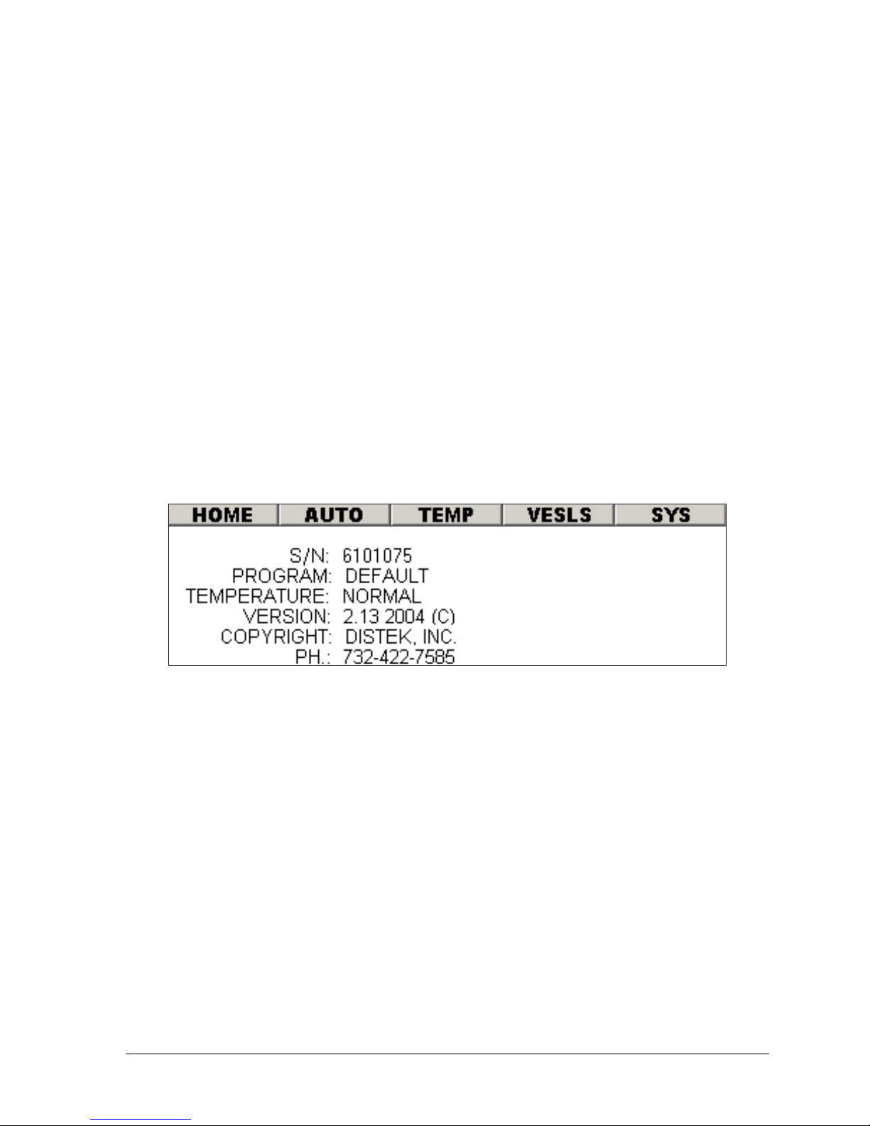
Within the System Configuration section, selecting the ABOUT menu item (see
Figure 3-6) will display the window shown in the figure below. This screen displays
the following information:
S/N Unit's serial number
TCS S/N TCS’s serial number (only
valid for a 6300 and a the
TCS FW Rev. 1.53 or
higher)
PROGRAM Default or Waters
TEMPERATURE Normal or Hi-Temp
VERSION Firmware revision
COPYRIGHT Distek, Inc.
PH. Company phone number
Figure 3-7: About Window
User Configuration
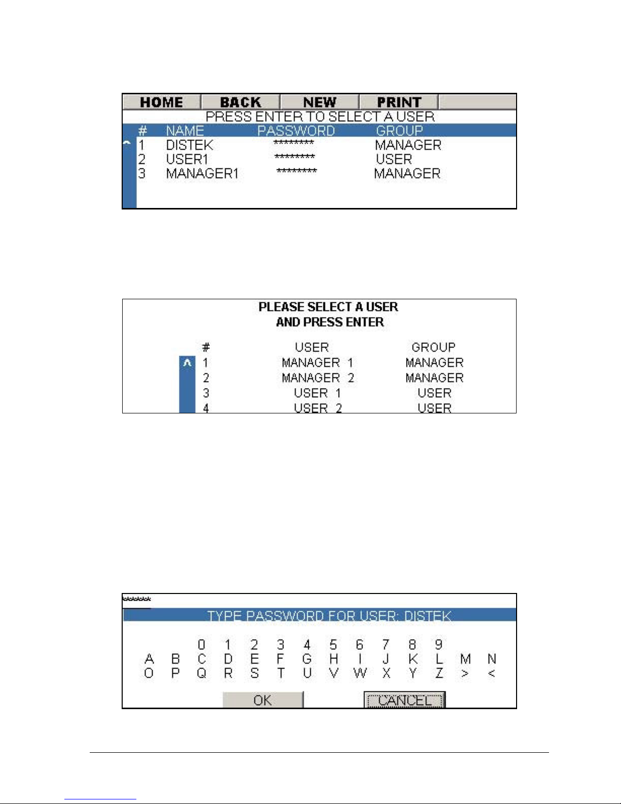
Selecting 'SYSTEM CONFIG' from the Main Screen, then selecting the 'USER CONFIG'
button on the System Administration Wizard screen (see Figure 3-5) will open the
following window:
Operation Manual: Evolution Series
Page 50
Chapter 3: Operation
3-13
Figure 3-8: User Configuration Screen
Login Procedures
After the system boots up or after an operator logs out, the Login screen will
appear:
Figure 3-9: Login Screen
1. Move through the user list using the arrow buttons on the keypad.
2. Once the desired user is selected press the ENTER button.
3. The virtual keyboard screen will be displayed (see Figure 3-10). Enter the
password using the keyboard. Use the arrow keys to navigate through the
keyboard and press ENTER to select an alphanumeric value.
4. Once the password is entered navigate to the OK button and press ENTER.
5. If the password is correct the unit will produce an audible beep and proceed
to the main menu (see Figure 3-4).
Operation Manual: Evolution Series
Figure 3-10: Virtual Keypad
Page 51
Chapter 3: Operation
3-14
Creating a New Account
The operator logged into the system must be part
of the Manager group to create a new user.
A maximum of 25 accounts can be created.
1. Highlight the SYS. menu or SYSTEM CONFIG button from the Main screen and
press ENTER (see Figure 3-4).
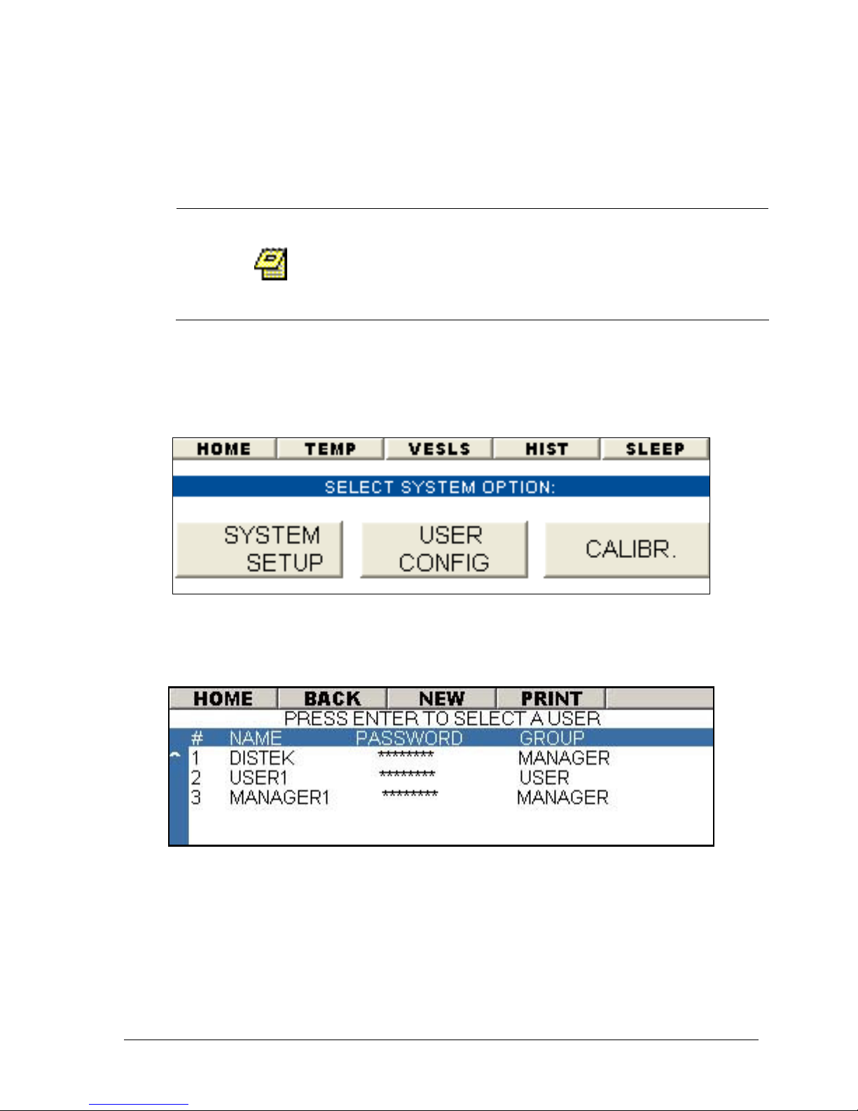
2. Highlight the USER CONFIG button and press ENTER (see Figure 3-11).
Figure 3-11: System Configuration Wizard
3. Highlight NEW from the menu bar and press ENTER (see Figure 3-12).
Figure 3-12: User Configuration Screen
4. The virtual keyboard screen will be displayed. Enter the username using
the keyboard. Use the arrow keys to navigate through the keyboard and
press ENTER to select an alphanumeric value (maximum of 8 characters).
5. Once the username is entered navigate to the OK button and press ENTER.
Operation Manual: Evolution Series
Page 52
Chapter 3: Operation
3-15
6. The new user will now be added to the user list. The default password will
be the same as the username.
7. The "PASSWORD" field will now be active. To change the default password,
press ENTER to activate the virtual keypad.
8. Enter the password using the keyboard. Use the arrow keys to navigate
through the keyboard and press ENTER to select an alphanumeric value
(maximum of 8 characters).
9. Once the password is entered navigate to the OK button and press ENTER.
10. To change the "GROUP" setting, navigate to this field using the arrows keys.
Set the desired group privilege for the user by using the + and – buttons to
toggle between “USER” and “MANAGER”.
Changing the Privileges of an Existing Account
The operator logged into the system must be part
of the Manager group to modify an existing user.
1. Using the arrow keys scroll through the fields until the “GROUP” field is
highlighted for the desired user. Toggle between USER and MANAGER using
the + or – buttons.
Changing a Password
The operator logged into the system must be part
of the Manager group to change a password.
1. Using the arrow keys scroll through the fields until the “PASSWORD” field is
highlighted for the desired user.
2. Press ENTER.
3. The virtual keyboard screen will be displayed. Enter the username using
the keyboard. Use the arrow keys to navigate through the keyboard and
press ENTER to select an alphanumeric value (maximum of 8 characters).
4. Once the username is entered navigate to the OK button and press ENTER.
Operation Manual: Evolution Series
Page 53
Chapter 3: Operation
3-16
Deleting an Account
The operator logged into the system must be part
of the Manager group to delete a user.
1. Highlight a user from the user list (highlight the Password or Group field).
2. Press the DEL key from the keypad.
3. The system will display a message box: “USER: USER_NAME
CONFIRM DELETION?” Select YES to confirm the deletion.
Temperature Calibration
When selecting the CALIBR button the unit will prompt
the use of a password. The password is 'EVOCAL' and
only will be accepted if the user logged into the system
has Manager priveleges. Because calibration of the unit
can cause serious performance issues, this added level
of security was implemented.
Accurate calibration of the temperature probes is essential for proper operation of
the Distek Evolution Dissolution System. Factory calibration provides accuracy
within ±0.1ºC. Care must be taken when re-calibrating in the field, in order to
realize the full accuracy and range of the temperature sensing system.
All installed temperature probes are factory-calibrated using an NIST-traceable
digital reference thermometer, the Distek TempChek. Distek recommends a 6month calibration cycle, during which each probe is checked and adjusted by this
Operation Manual: Evolution Series
Figure 3-13: Main Calibration Screen
Page 54

Chapter 3: Operation
3-17
method to the specified accuracy. Only qualified personnel should adjust the
unit's calibration.
Interim temperature checks can be made in two ways:
A. The calibration probe supplied with the Evolution unit can be compared
using the TempChek or any calibrated glass thermometer readable to
0.01ºC and accurate to ±0.02ºC. Each vessel temperature probe can then
be checked (and re-calibrated if needed) using the calibration probe.
B. Alternatively, each vessel probe can be checked and re-calibrated with
TempChek, or any calibrated thermometer.
The Evolution System will automatically detect whether a High-Temperature
Calibration or a Low-Temperature Calibration will be performed based on the
temperature of the probe. If the temperature of the probe is below 25°C and 15°C
below the last high-temperature calibration a Lo-Cal will be performed. If the
temperature of the probe is above 25.05°C and 15°C higher than the last lowtemperature calibration a Hi-Cal will be performed. Use 700-1000ml water in each
vessel. It is suggested to use cool water between 18º and 22º C to perform LowTemperature Calibration and warm water between 38º and 42º C to perform HighTemperature Calibration. There must be a difference of at least 15° between the
Lo-Cal temperature and the Hi-Cal temperature in order for the calibration
procedure to work properly.
For accurate calibration use PADDLES. Basket stirring is not adequate for precise
calibration. Calibration settings are saved in non-volatile memory and are
retained after the unit is powered down.
Verify accuracy of low temperature calibration
(18-22º C) before performing High-Temperature
Calibration.
Heaters turn off automatically when the Calibration screen is accessed. The
reason is to stabilize vessel temperature during the calibration procedure by
preventing the high-powered heaters from raising temperatures rapidly.
Operation Manual: Evolution Series
Page 55
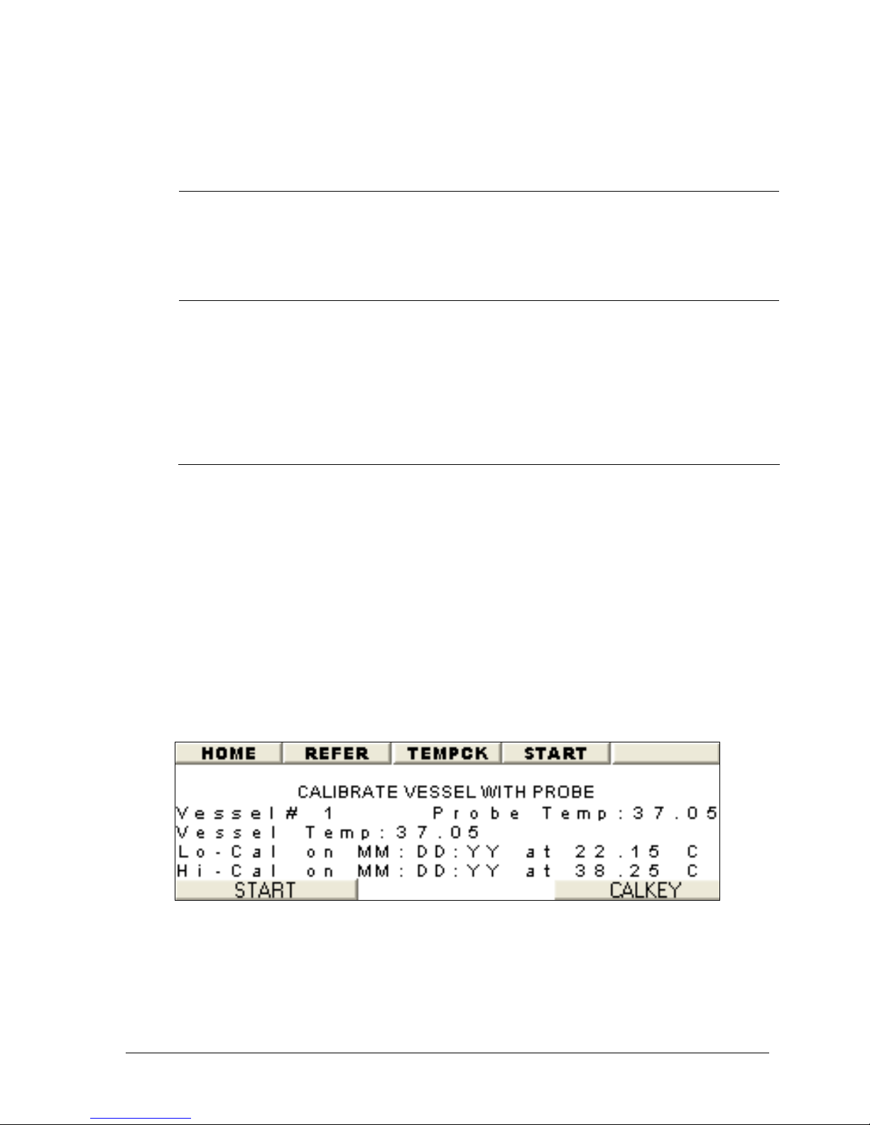
Chapter 3: Operation
3-18
Calibrate Using Evolution Calibration Probe
The following steps describe the procedure for calibration:
1. Install 7 vessels with 900 mls of water.
2. Install all Paddle blades.
3. Place the calibration probe in the vessel to be calibrated.
4. Set the vessel number on the screen using the + or – button (See Figure
3-14).
5. Wait for both calibration probe and vessel temperatures to stabilize.
6. Press START to calibrate the vessel.
7. Move calibration probe to next vessel to be calibrated.
8. Repeat step 2 through 5 until all vessels have been calibrated.
Check Evolution System calibration probe against
a calibrated reference before performing this
procedure. Check at low and high temperatures.
Probe is factory-calibrated.
Each original probe, including the calibration
probe, was factory calibrated before your
Evolution System was shipped. Low-Temperature
Calibration is only needed if the calibration
values are deleted, or a new probe is installed.
Otherwise, proceed to High-Temperature
Calibration.
Operation Manual: Evolution Series
Figure 3-14: Calibrate with Calibration Probe
Page 56
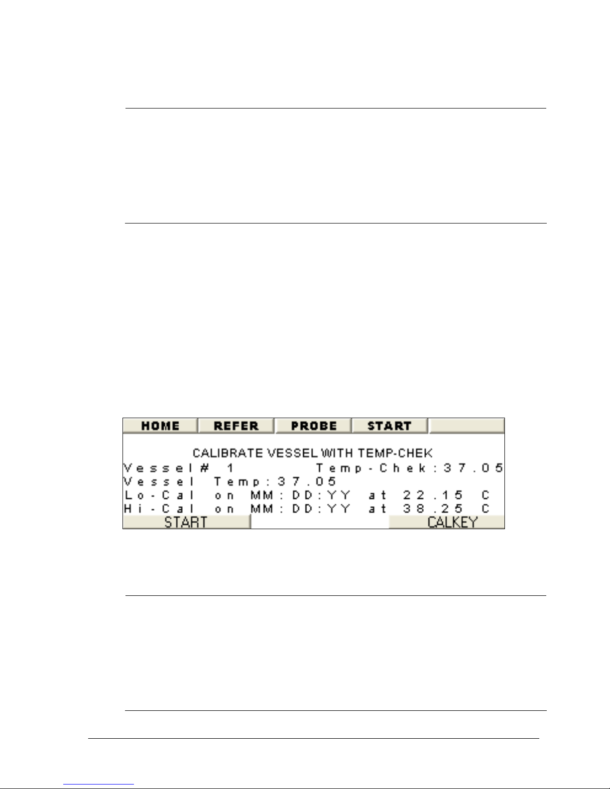
Chapter 3: Operation
3-19
Calibrate Using TempChek Digital Thermometer
Each original probe, including the calibration
The following steps describe the procedure for calibration:
1. Install 7 vessels with 900 mls of water.
2. Install all Paddle blades.
3. Connect TempChek to RS-232 port (located on the side of unit) using Disteksupplied cable.
4. Place TempChek probe in vessel to be calibrated.
5. Set vessel number on the screen using the + or – button (See Figure 3-15).
6. Wait for both TempChek and vessel temperatures to stabilize.
7. Press START to calibrate.
8. Move the TempChek probe to next vessel to be calibrated.
9. Repeat step 2 through 6 until all vessels have been calibrated.
probe, was factory calibrated before your
Evolution System was shipped. Low-Temperature
Calibration is only needed if the calibration
values are deleted, or a new probe is installed.
Otherwise, proceed to High-Temperature
Calibration.
Calibrate Using NIST-Traceable Reference Thermometer
Operation Manual: Evolution Series
Figure 3-15: Calibrate using TempChek
Each original probe, including the calibration
probe, was factory calibrated before your
Evolution System was shipped. Low-Temperature
Calibration is only needed if the calibration
values are deleted, or a new probe is installed.
Otherwise, proceed to High-Temperature
Calibration.
Page 57
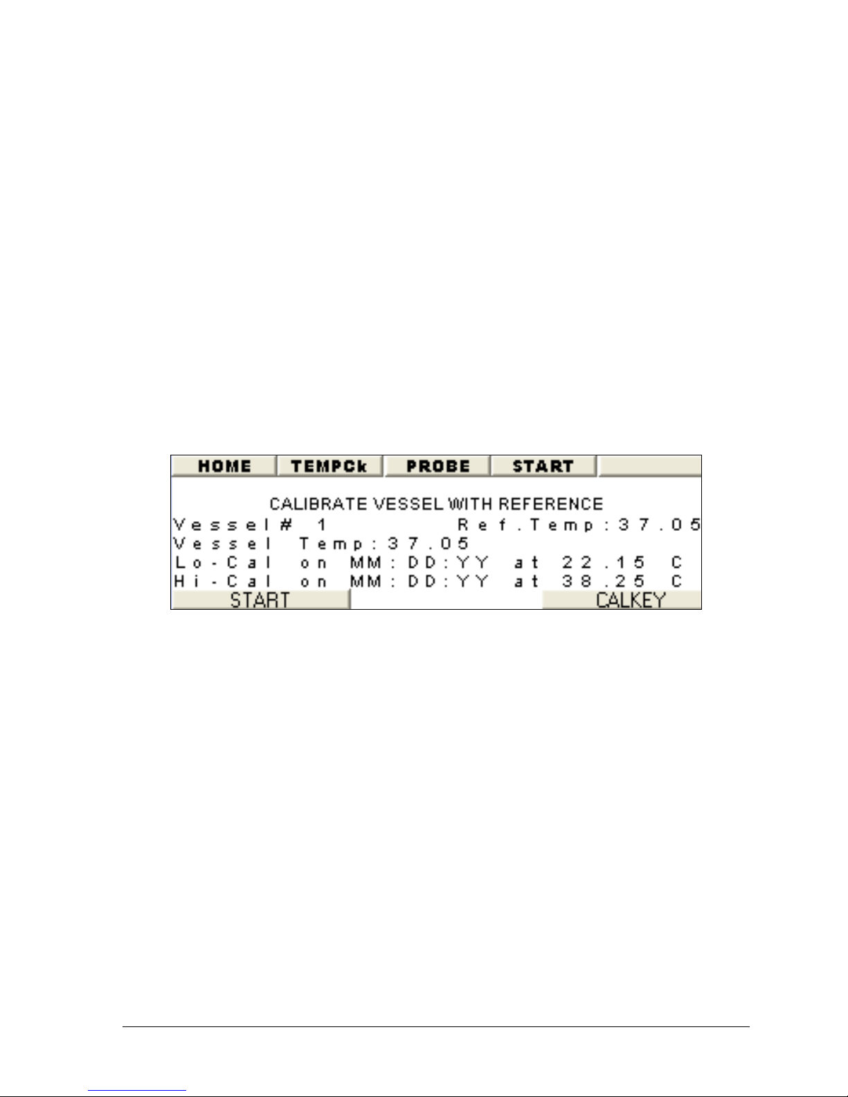
Chapter 3: Operation
3-20
The following steps describe the procedure for calibration:
1. Install 7 vessels with 900 mls of water.
2. Install all Paddle blades.
3. Place reference thermometer in the vessel to be calibrated.
4. Set vessel number on screen using the + or – button (See Figure 3-16).
5. Wait for both reference and vessel temperatures to stabilize.
6. Read temperature directly from reference thermometer.
7. Highlight the Ref. Temp. field and adjust the temperature value using the +
or – buttons.
8. When Ref. Temp. on the screen matches actual reference reading, press
START to calibrate.
9. Move reference thermometer to next vessel to be calibrated.
10. Repeat step 2 through 6 until all vessels have been calibrated.
Figure 3-16: Calibrate using Reference
Calibrate calPROBE Using TempChek Digital Thermometer
1. Connect TempChek to RS-232 port (located on the side of unit) using Disteksupplied cable.
2. Place TempChek probe and the calibration probe in the same vessel.
3. Using the + or – button set vessel number on the screen to 8.
4. Wait for both TempChek and vessel temperatures to stabilize.
5. Press START to calibrate.
Operation Manual: Evolution Series
Page 58
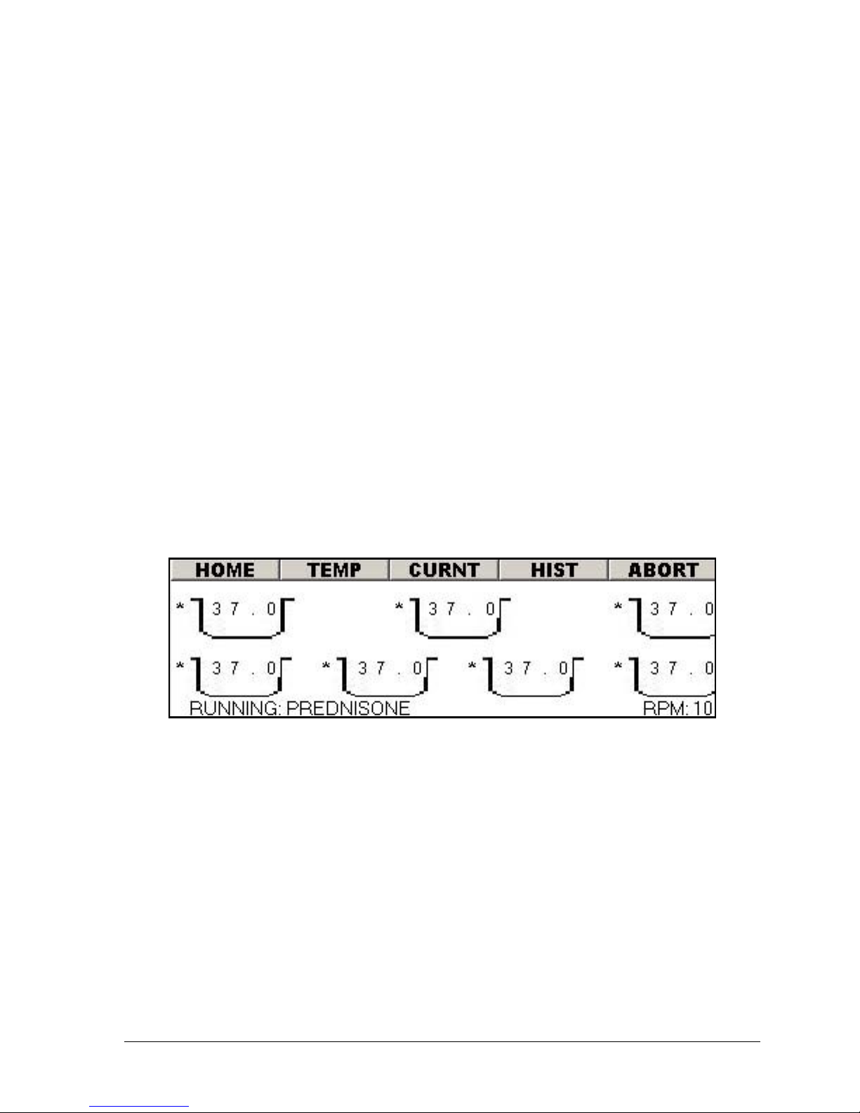
Chapter 3: Operation
3-21
Calibrate calPROBE Using NIST-Traceable Reference Thermometer
1. Place reference thermometer and the calibration probe in the same vessel.
2. Using the + or – button set vessel number on the screen to 8.
3. Wait for both reference and vessel temperatures to stabilize.
4. Read temperature directly from reference thermometer.
5. Highlight the Ref. Temp. field and adjust the temperature value using the +
or – buttons.
6. When Ref. Temp. on the screen matches actual reference reading, press
START to calibrate.
Display Screens
All Display screens are accessible while in Manual Mode or Auto Test Mode. Use
menu bar along the top of the screen or the wizards from the Main screen to scroll
through the various Display screens as shown in the following sections.
Temperature Screen
Figure 3-17: Vessel Temperature Display Screen
• Figure 3-17 shows the temperatures (in Celsius) in vessels 1 through 7.
• The indication at the lower left of the screen shows the name and status of the
automatic test currently running. This will indicate "Manual Mode" while
running in manual mode. The valid status options are: Idle, Pre-Heat and
Running.
• The RPM will be displayed in the lower right of the screen.
• In Figure 3-18 and Figure 3-19, the asterisk to the left of the vessel number
indicates the vessel heater is enabled. The two figures show vessels 1 through
7 are enabled. Temperature probe 8 is the built-in calibration probe.
• The TEMP button on the menu bar will toggle between Figure 3-17 and Figure
3-18.
Operation Manual: Evolution Series
Page 59
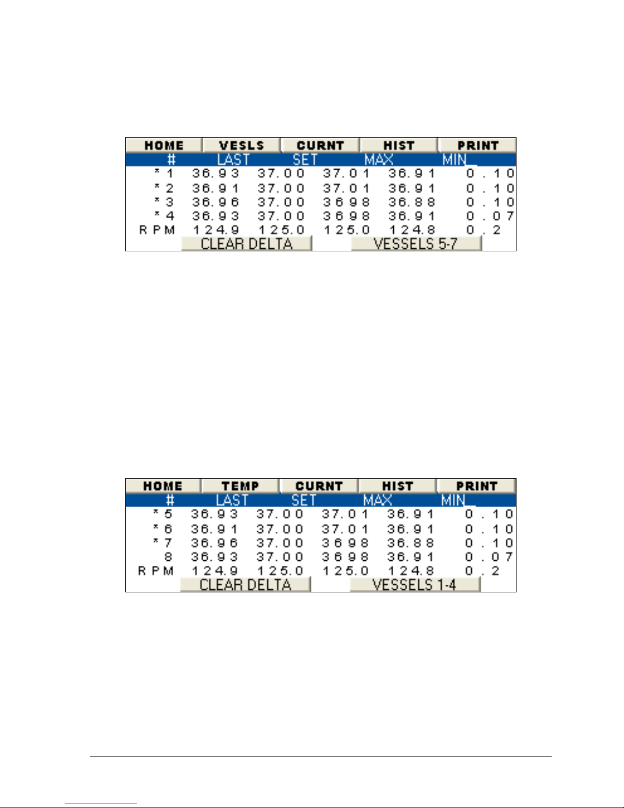
Chapter 3: Operation
3-22
Temperature and RPM Screen
Figure 3-18: Temperature and RPM Monitor (Vessels 1-4)
• The screen in Figure 3-18 shows temperatures in vessels 1-4 and RPM values.
The "LAST" column shows the current value and the "SET" column indicated the
temperature set point.
• The "MAX" and "MIN" columns record the temperature and RPM range during a
test. "DEL" is short for delta, which is the difference between the MAX and MIN
values.
• To reset all DEL values to zero in Manual Mode, press the "CLEAR DELTA"
button. The elapsed time indicator on the top LED will be reset to zero. This
is only possible when running in Manual Mode!
• Selecting the button labeled "Vessel 5-7" will display another temperature and
RPM monitor screen showing the same values for the other vessels.
• The TEMP button on the menu bar will toggle between Figure 3-17 and Figure
3-18.
Figure 3-19: Temperature and RPM Monitor (Vessels 5-7)
Operation Manual: Evolution Series
Page 60
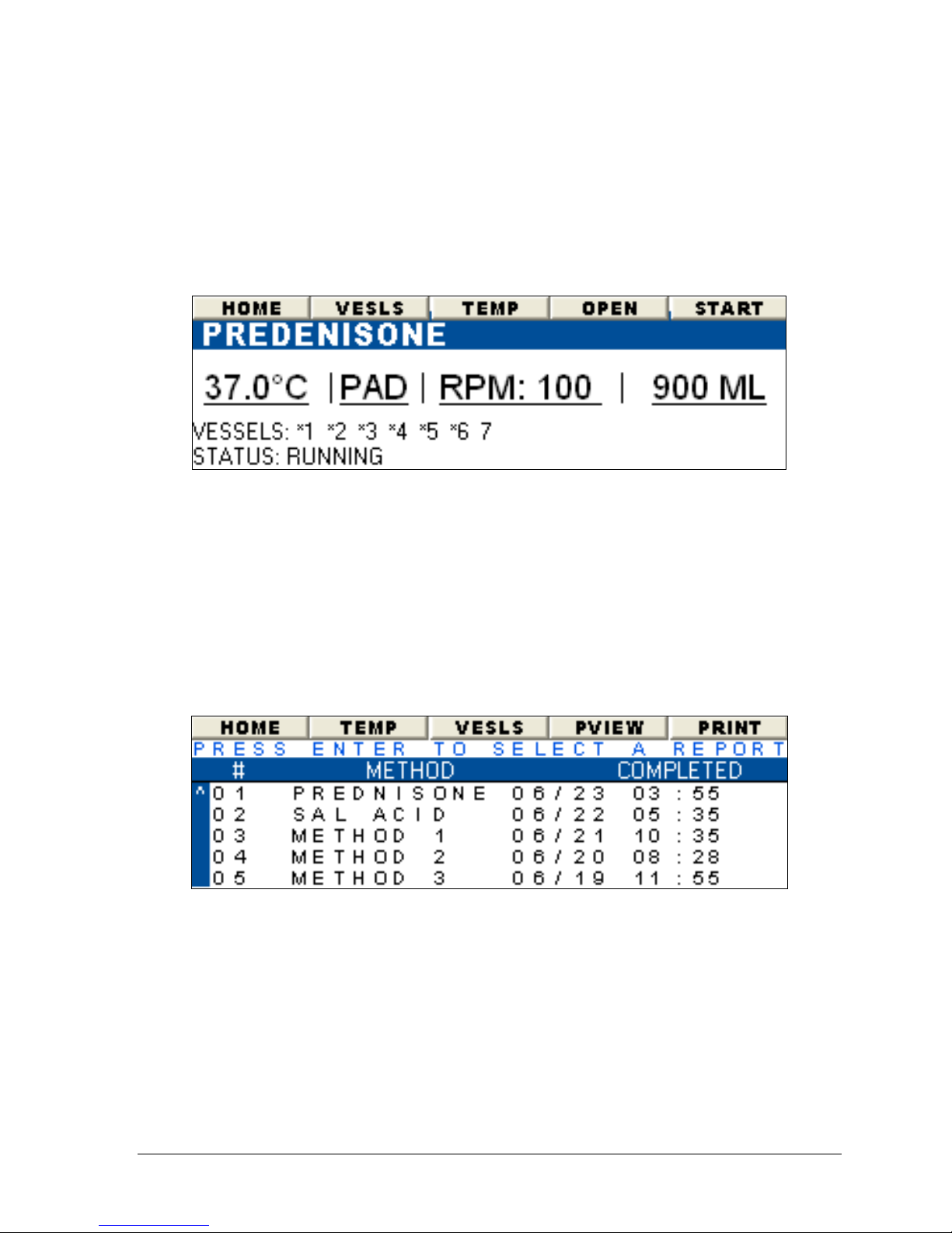
Chapter 3: Operation
3-23
Current Method
The display screen in Figure 3-20 summarizes the settings in use for the current
Auto Test method. Vessels 1-7 are enabled. Test temperature is set to 37.0°C
and the RPM is set to 100.
Figure 3-20: Current Method Details
Report History
The report history screen is accessed by selecting the "HIST" button on the menu
bar. This button is found on several screens throughout the user interface such as
the AUTO MODE wizard screen (see Figure 3-22), the MANUAL MODE wizard (see
Figure 3-27) and most of the Display View screens.
Figure 3-21 lists the last 40 Automatic Tests that have been run on the unit. Tests
which were aborted will display "Aborted" in the "Completed" column.
Figure 3-21: Report History
Operation Manual: Evolution Series
Page 61
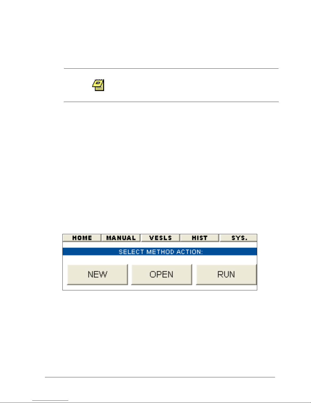
Chapter 3: Operation
3-24
Printing a Saved Report
A printer must be connected to the unit via the
parallel port in order to produce a printout.
A maximum of 40 reports can be created.
1. Navigate to a screen that contains a HIST button on the menu bar such as
the AUTO MODE wizard screen (see Figure 3-23), the MANUAL MODE wizard
(see Figure 3-27) or most of the Display View screens.
2. Highlight the HIST menu and press ENTER.
3. The report screen (see Figure 3-21) will display the stored reports that have
been run on the instrument (maximum of 16 stored reports). Highlight the
desired method from the list using the arrows keys and press ENTER.
4. Highlight the PRINT menu and press ENTER.
Working with Methods (Automatic Mode)
The Evolution Dissolution System is capable of storing 100 methods. These preprogrammed methods allow for quick and easy operation of the unit. While in
automatic mode the operator can perform the following method actions: new,
open, run, view current and print.
Figure 3-22: Auto Mode Wizard
Selecting a Method to Run
1. From the main screen (see Figure 3-4) select either the menu bar option
AUTO (go to step 3) or the AUTO MODE wizard button (display Figure 3-23).
2. Select RUN. The screen displayed will be similar to one in Figure 3-23.
3. Using the up or down arrow keys highlight a method from the method list.
4. Press the RUN/STOP or ENTER key to run the method.
5. Select YES from the displayed message.
Operation Manual: Evolution Series
Page 62
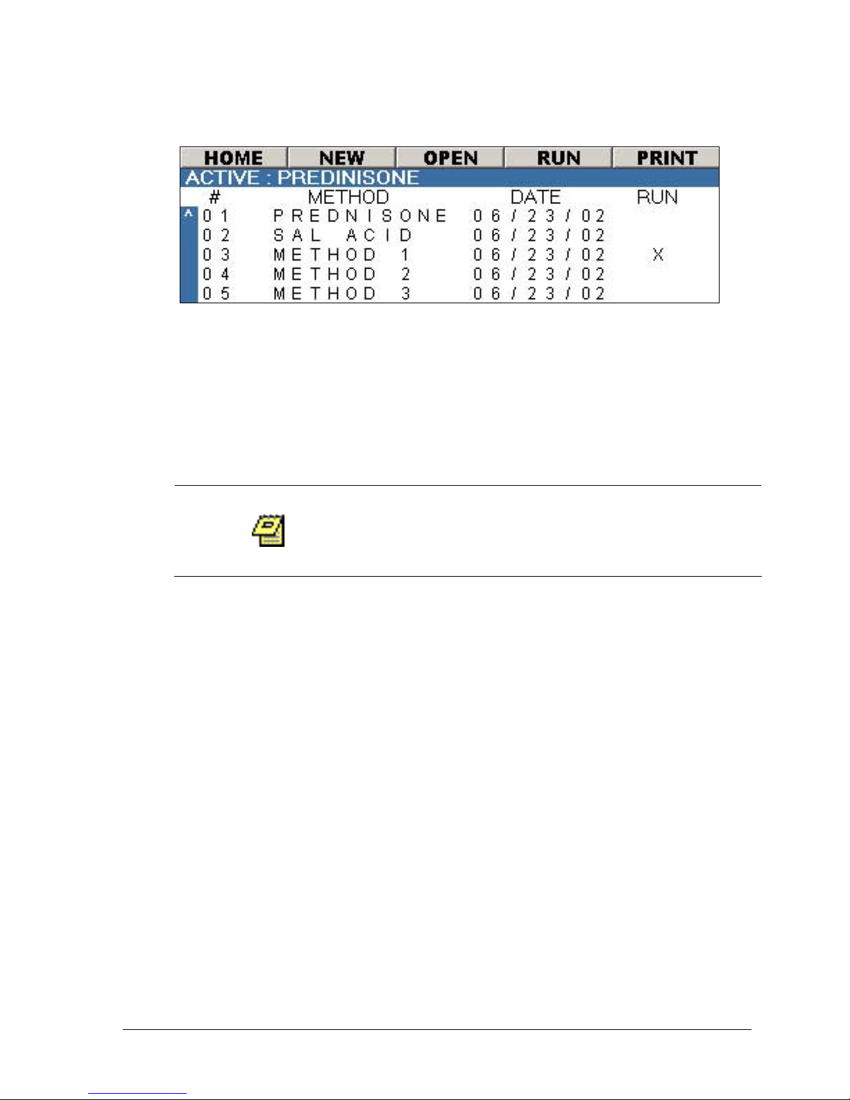
Chapter 3: Operation
3-25
Figure 3-23: Auto Mode Screen
Sorting the Method List
The method list shown in Figure 3-23 can be sorted by method name or date.
Simply highlight the METHOD field or DATE field and click ENTER on the keypad.
Clicking ENTER will toggle between sorting A-Z and Z-A on the METHOD column or
ascending and descending on the DATE column.
Programming a New Method
The operator logged into the system must be part
of the manager group to create a new method.
A maximum of 100 methods can be created.
1. From the main screen (see Figure 3-4) select either the menu bar option
AUTO (go to step 3) or the AUTO MODE wizard button.
2. Select NEW.
3. Enter the method name using the virtual keyboard. Use the arrow keys to
navigate through the keyboard and press ENTER to select an alphanumeric
value (maximum of 16 characters).
4. Once the method name is entered navigate to the OK button and press
ENTER. The screen in Figure 3-24 will be displayed.
5. Using the arrow keys highlight the TEST TEMP field. Press the + or – button
to set the desired value.
6. Using the arrow keys highlight the VOL field. Press the + or – button to set
the desired value.
7. Using the arrow keys highlight the STIR ELEM field. Press the + or – button
to toggle between PADDLE and BASKET.
8. Using the arrow keys highlight the TEST RPM field. Press the + or – button
to set the desired value.
9. Using the arrow keys highlight the DUR field. Press the + or – button to set
the desired value.
Operation Manual: Evolution Series
Page 63
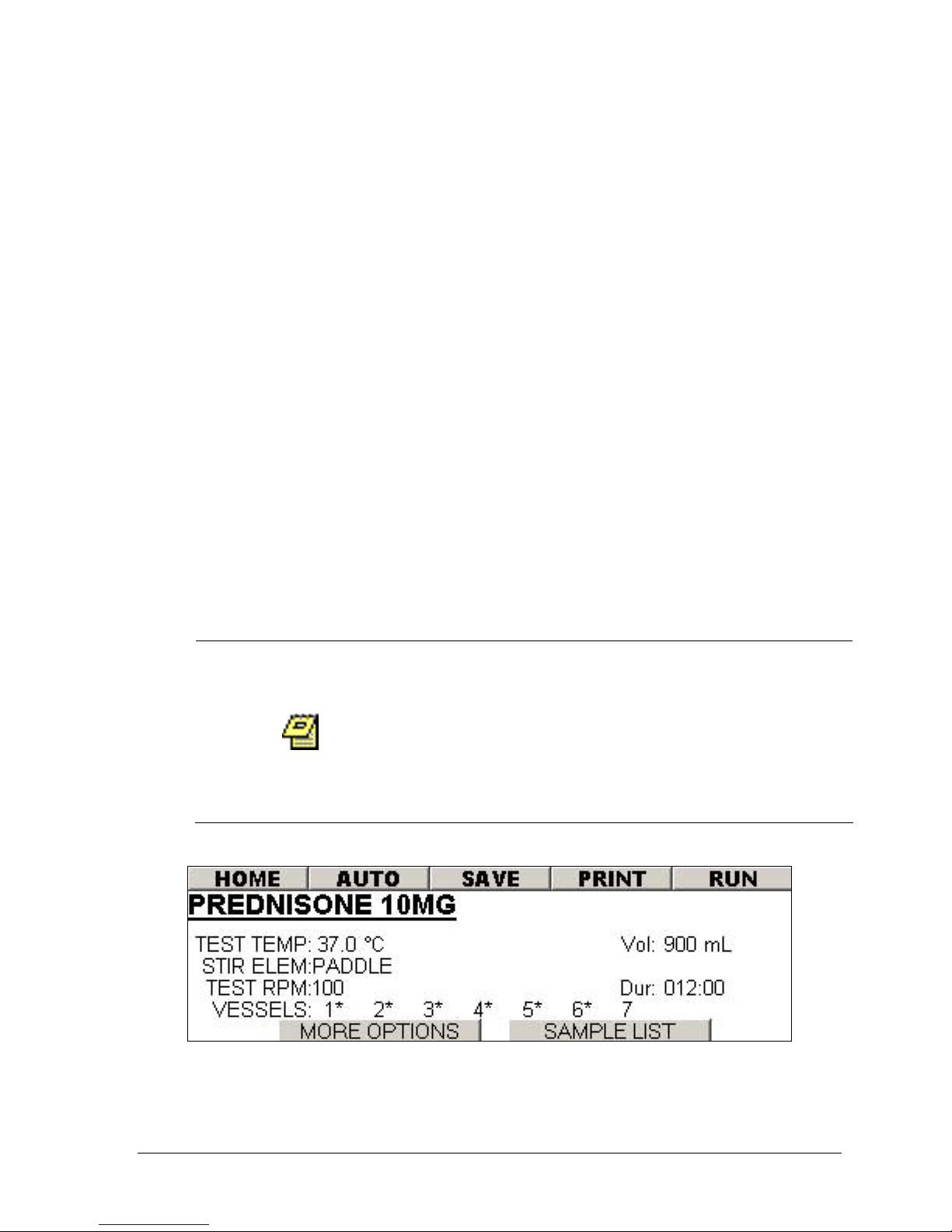
Chapter 3: Operation
3-26
10. Using the arrow keys highlight the space to the left of the VESSEL number.
Press the ENTER button toggle between a blank space or a *. An *
represents enabling a vessel.
11. Using the arrow keys highlight the MORE OPTIONS button and press ENTER.
The screen in Figure 3-25 will be displayed.
12. Using the arrow keys highlight the INF RPM field. Press the + or – button to
set the desired value.
13. Using the arrow keys highlight the DUR field. Press the + or – button to set
the desired value.
14. Using the arrow keys highlight the Staggered Drop field. Press the + or –
button to set the desired delayed drop time in seconds.
15. Using the arrow keys highlight the Report field. Press the + or – button to
toggle between ON or OFF.
16. Using the arrow keys highlight the SAMPLE LIST button and press ENTER.
The sample list screen in Figure 3-26 will be displayed.
17. With the highlighted field in the sample list press ENTER to add a new
sample timepoint. Highlight the INSERT button and press ENTER to insert a
timepoint in the sample list.
18. Highlight the time values in the list and use the + or – button to make the
necessary modifications.
19. Highlight the BACK button and press ENTER.
20. Highlight the SAVE button and press ENTER.
When running a staggered drop test it is possible
to have a conflict between a sampling time point
and a tablet drop event (i.e. a short staggered
drop interval and a quick first time point). If this
occurs the Evolution unit will prioritize the
sampling event and extend the staggered drop
interval.
Operation Manual: Evolution Series
Figure 3-24: Method Screen
Page 64
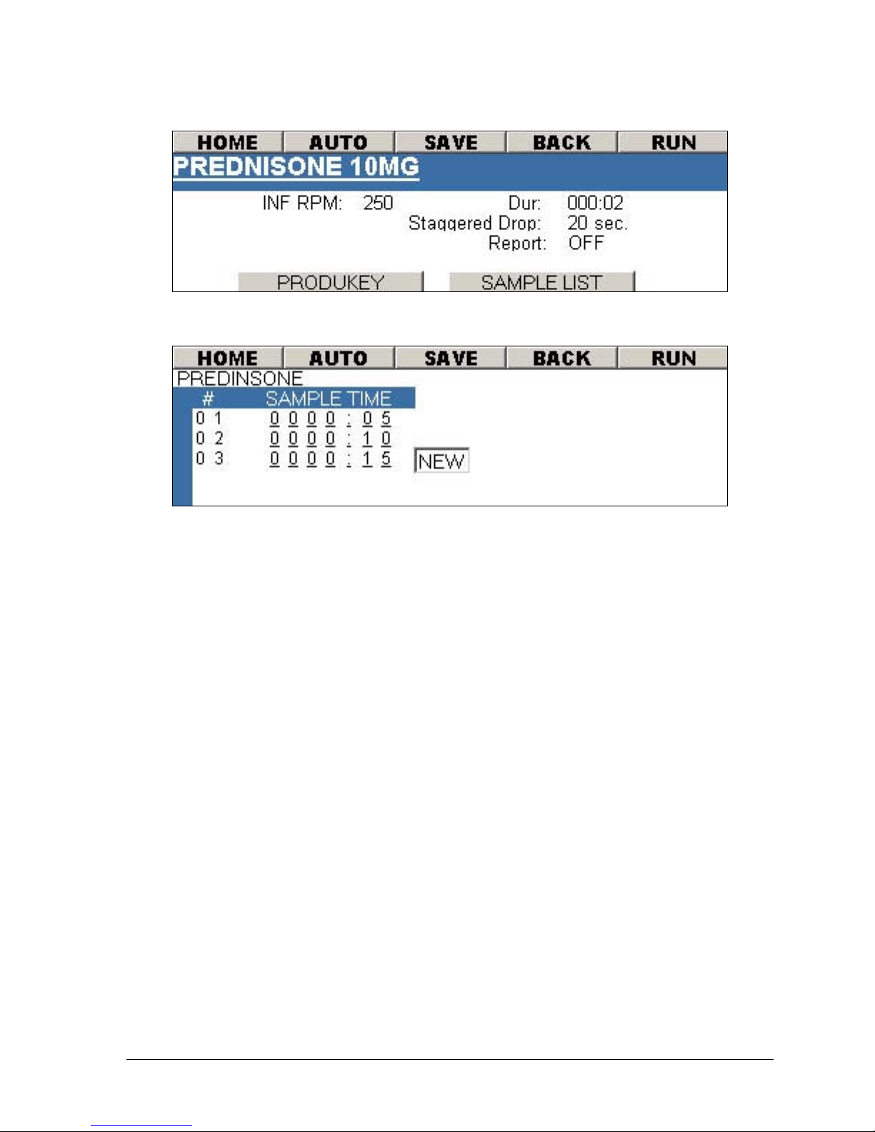
Chapter 3: Operation
3-27
Figure 3-25: Method Screen – More Options
Figure 3-26: Method Screen – Sample List
Running a Simultaneous Drop with Paddles
1. Run the method (see Selecting a Method to Run on page 3-24).
2. After the unit has completed pre-heating the following message will be
displayed:
VESSEL TEMP HAS BEEN REACHED.
PRESS ENTER AND DROP
DOSAGE FORM.
3. Press the ENTER key. The following message will be displayed
PLEASE DROP DOSAGE FORM
STIRRING BEGINS IN XX SECONDS
OR PRESS ENTER TO START TEST.
The RPM will pause for 20 seconds to enable introduction of the dosage
form.
4. Introduce the dosage form into each vessel.
5. The test will begin once the 20 second has expires or press ENTER to begin
immediately.
Operation Manual: Evolution Series
Page 65

Chapter 3: Operation
3-28
Running a Simultaneous Drop with Baskets
1. Run the method (see Selecting a Method to Run on page 3-24).
2. After the unit has completed pre-heating the following message will be
displayed:
VESSEL TEMP HAS BEEN REACHED.
RAISE STAGE, ATTACH BASKETS AND
LOWER STAGE TO START TEST.
3. Raise the stage board (drive plate) and attach all the baskets to the shafts.
4. Lower the stage board and the test will automatically begin.
Running a Staggered Drop with Paddles
1. Run the method (see Selecting a Method to Run on page 3-24).
2. After the unit has completed pre-heating the following message will be
displayed:
VESSEL TEMP HAS BEEN REACHED.
CONTINUE?
3. Select YES.
4. The following message will be displayed:
HOLD SHAFT #X, DROP DOSAGE FORM
RELEASE SHAFT THEN PRESS ENTER.
where X represents the vessel number
5. Hold the shaft securely to prevent the paddle from spinning and introduce
the dosage form.
6. Release the shaft and press ENTER.
7. The unit will cycle through all the vessel positions based on the staggered
drop interval time.
Running a Staggered Drop with Baskets
1. Run the method (see Selecting a Method to Run on page 3-24).
2. After the unit has completed pre-heating the following message will be
displayed:
VESSEL TEMP HAS BEEN REACHED.
CONTINUE?
3. Select YES.
4. The following message will be displayed:
RAISE SHAFT #X
AND ATTACH BASKET.
where X represents the vessel number
5. The unit will automatically detect the shaft is raised and display the
following message:
LOWER SHAFT #X
TO START.
Operation Manual: Evolution Series
Page 66
Chapter 3: Operation
3-29
6. The system will automatically detect the lowering of the shaft and begin
the test. There will be a very slight delay due to the response of the unit
prior to the test starting. If this is not acceptable press ENTER at any time
after the shaft has been lower to begin the test immediately.
Open/View an Existing Method
If the operator is logged into the system with Manager
group privileges then the menu bar will contain a
selection for OPEN. If the operator is logged in with
USER group privileges then the menu bar will contain a
selection for VIEW because a USER does not have access
to modify a method.
There are 2 ways to open a method:
Method 1: Using the Auto Mode Wizard
1. From the main screen (see Figure 3-4) highlight the AUTO MODE wizard
button and press ENTER.
2. Highlight OPEN and press ENTER. The screen in Figure 3-23 will be
displayed.
3. Use the arrow keys to highlight the method from the method list and press
ENTER.
4. Highlight the menu bar item OPEN and press ENTER.
Method 2: Using the menu
1. From the main screen (see Figure 3-4) highlight the menu bar option AUTO
and press ENTER. The screen in Figure 3-23 will be displayed.
2. Use the arrow keys to highlight the method from the method list and press
ENTER.
3. Highlight the menu bar item OPEN and press ENTER.
Operation Manual: Evolution Series
Page 67
Chapter 3: Operation
3-30
Modify a Saved Method
The operator logged in to the system must be part of
the Manager group to modify a method.
The method name of a saved method cannot be
modified. Modifying the method name will create
a new method using the modified name.
1. From the main screen (see Figure 3-4) select either the menu bar option
AUTO (go to step 3) or the AUTO MODE wizard button.
2. Highlight the button OPEN and press ENTER.
3. Highlight the method to be modified from the method list and press ENTER.
4. Highlight the menu bar item OPEN and press ENTER.
5. Make the necessary modification to the method. See Figure 3-24, Figure
3-25 and Figure 3-26.
6. Upon completion of modification highlight SAVE on the menu bar and press
ENTER.
Deleting a Method
The operator logged into the system must be part of the
Manager group to delete a method.
1. From the main screen (see Figure 3-4) select either the menu bar option
AUTO (go to step 3) or the AUTO MODE wizard button.
2. Highlight the button OPEN and press ENTER.
3. Highlight the method to be deleted from the method list and press
ESC/DELETE.
Copy a Saved Method to a New Name
1. From the main screen (see Figure 3-4) select either the menu bar option
AUTO (go to step 3) or the AUTO MODE wizard button.
2. Highlight the button OPEN and press ENTER.
3. Highlight the method to be modified from the method list and press ENTER.
4. Highlight the menu bar item OPEN and press ENTER.
5. Highlight the method name field and press ENTER.
6. A virtual keypad will be displayed (see Figure 3-10). Use the arrow keys to
navigate through the keyboard and press ENTER to select an alphanumeric
value (maximum of 16 characters).
Operation Manual: Evolution Series
Page 68

Chapter 3: Operation
3-31
7. Once the method name is entered navigate to the OK button and press
ENTER.
8. Make the necessary modification to the method. See Figure 3-24, Figure
3-25 and Figure 3-26.
9. Upon completion of modification highlight the menu bar item SAVE and
press ENTER.
Printing Method Parameters
The system is capable of storing a method audit trail that is saved with the
method. This feature will display all the method changes for the past fifty saved
changes. After fifty changes have occurred the system will prompt the user that
older changes will be overwritten with the new changes. If this is not acceptable,
the user should copy this method to a new name which will then reset the method
history. See Appendix E for sample printouts.
1. From the main screen (see Figure 3-4) select either the menu bar option
AUTO (go to step 3) or the AUTO MODE wizard button.
2. Highlight the button OPEN and press ENTER.
3. Highlight the method to be modified from the method list and press ENTER.
4. Highlight the menu bar item PRINT and press ENTER.
Working in Manual Mode
As an alternative to running in Automatic Mode the user is able to operate the
Evolution Dissolution System in Manual Mode. This mode allows for a simplified
technique of running the dissolution system when it is not necessary to program a
method.
Manual Mode is capable of operating the system by controlling all vessels or each
vessel individually. Figure 3-27 displays the available operation in Manual Mode
for an Evolution 6100 and Figure 3-28 shows the available action for an Evolution
6300.
Individual vessel control is only applicable to the
Evolution 6100 Bathless Dissolution System.
Operation Manual: Evolution Series
Page 69
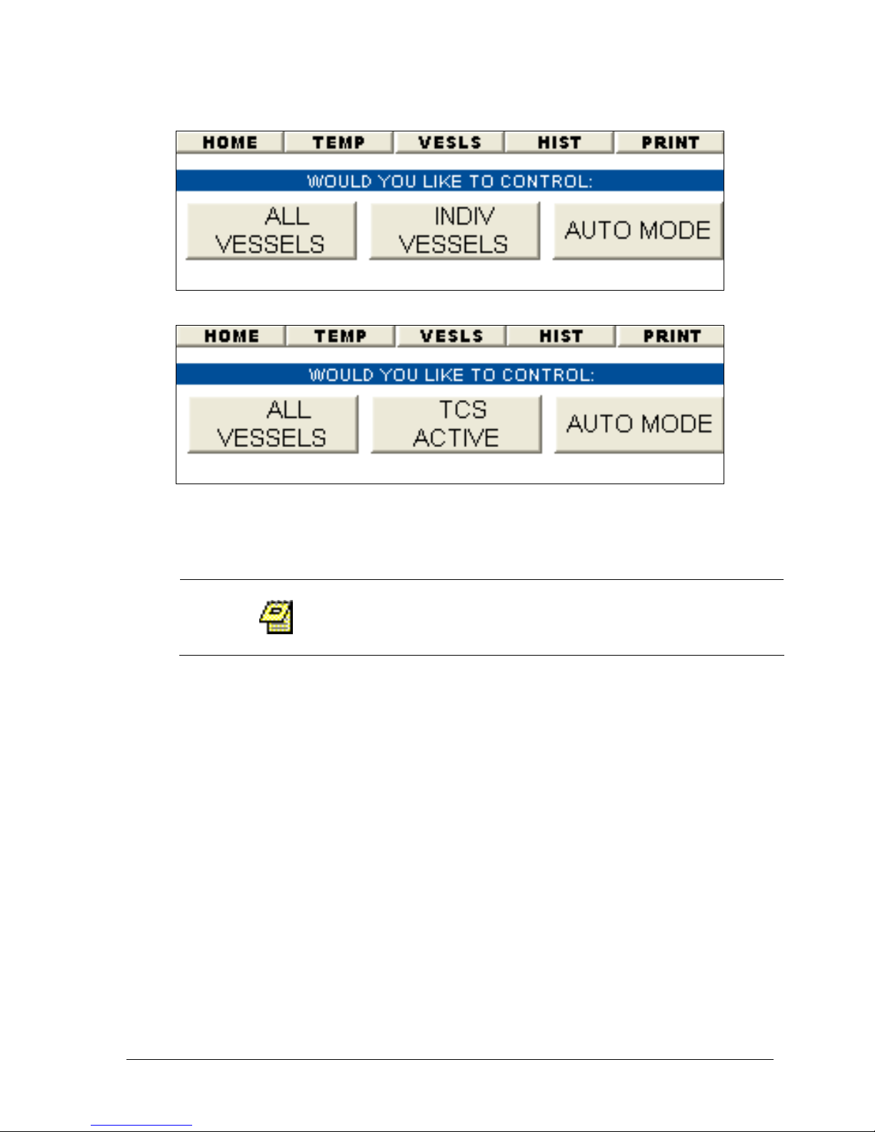
Chapter 3: Operation
3-32
Figure 3-27: Manual Mode Wizard – Evolution 6100
Figure 3-28: Manual Mode Wizard – Evolution 6300
Controlling Vessels Individually (Evolution 6100 Only)
This procedure is only valid for the Evolution 6100
Bathless Dissolution System.
The Evolution 6100 Bathless Dissolution System is capable of setting test
parameters individually for each vessel. The temperature, vessel volume and
stirring element can all be varied independently for each vessel (the RPM cannot
be individually set).
1. From the main screen (see Figure 3-4) select the MANUAL MODE wizard
button.
2. Select INDIV VESSELS. Figure 3-29 will be displayed.
3. Highlight the desired vessel icon and press ENTER.
4. Figure 3-30 will now be displayed.
5. Highlight the TEMP field. Using the + and – keys change to the desired test
temperature.
6. Highlight the STIR field. Using the + and – keys change to the desired
stirring element (PAD for paddles or BAS for baskets).
7. Highlight the VOL field. Using the + and – keys change to the desired test
volume.
Operation Manual: Evolution Series
Page 70
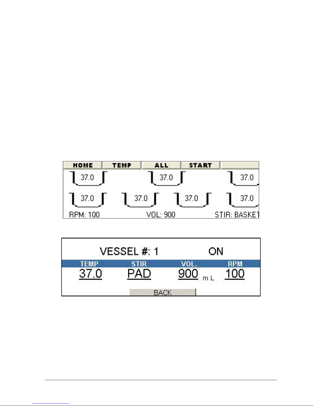
Chapter 3: Operation
3-33
8. Highlight the RPM field. Using the + and – keys change to the desired test
RPM.
9. Highlight the ON/OFF field. Using the + and – keys change to the desired
value (on or off).
10. To change setting for other vessels follow one of the two following
methods:
a. Highlight the VESSEL # position and using the + and – keys change to
the desired vessel number. Follow steps 5-9 to modify the test
settings.
b. Highlight the BACK button and press ENTER. Select the vessel to
modify from the screen displayed in Figure 3-29. Follow steps 5-9 to
modify the test settings.
11. Highlight the BACK button and press ENTER.
12. Highlight the START button on the menu bar and press ENTER.
Figure 3-29: Manual Mode, Individual Vessel Control
Figure 3-30: Manual Mode, Individual Vessel Control Settings
Controlling All Vessels
1. From the main screen (see Figure 3-4) select either the menu bar option
MANUAL (go to step 3) or the MANUAL MODE wizard button.
2. If using the wizard, select ALL VESSELS. Figure 3-31 will be displayed.
3. Highlight the higher vessel number listed on the first line.
4. Using the + and – keys change to the desired vessel number. For example if
the screen displays "VESSELS # 1 – 6" and you only need to run vessels 1
Operation Manual: Evolution Series
Page 71
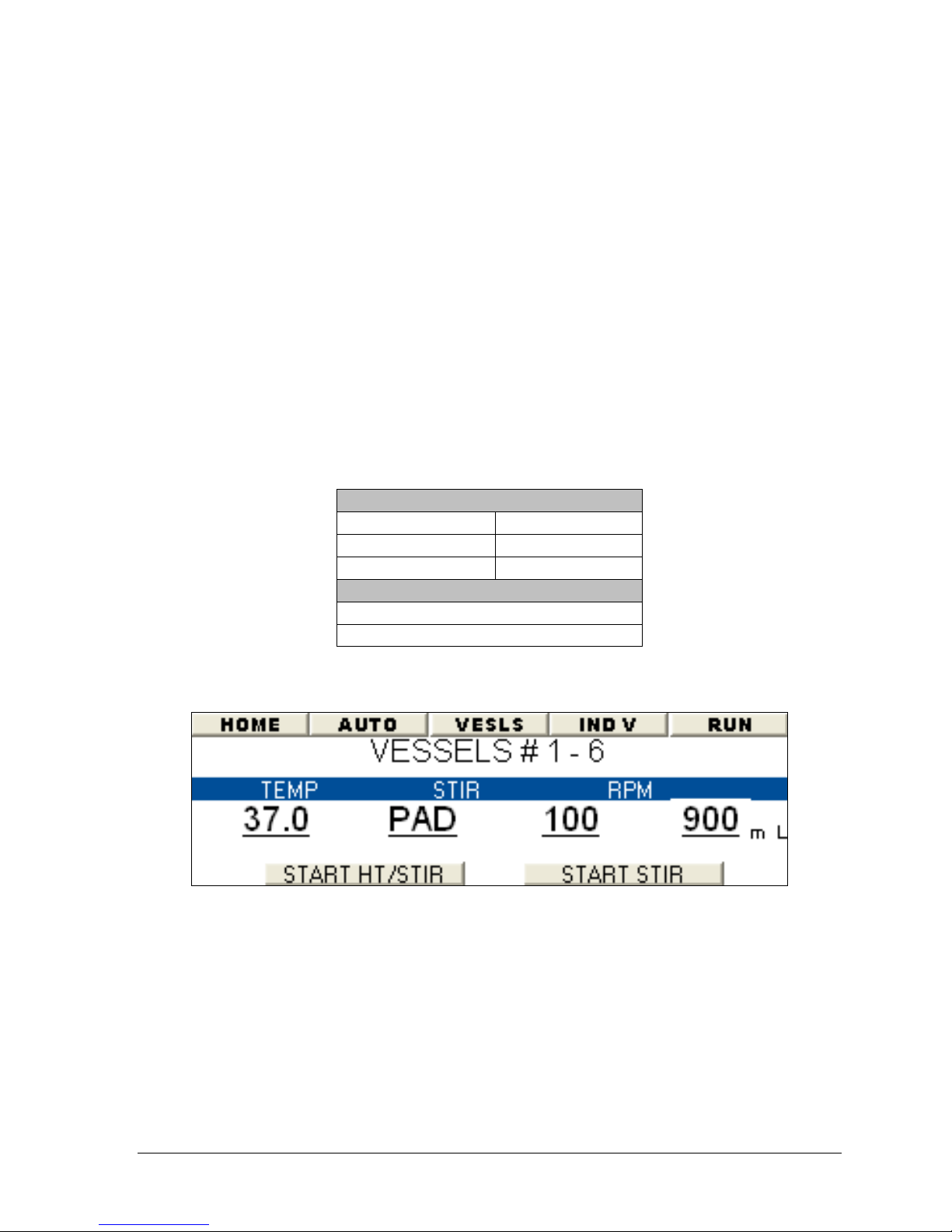
Chapter 3: Operation
3-34
through 4, highlight 6 and change this value to 4. The screen will now
display "VESSELS # 1 – 4".
5. Highlight the TEMP field. Using the + and – keys change to the desired test
temperature.
6. Highlight the STIR field. Using the + and – keys change to the desired
stirring element (PAD for paddles or BAS for baskets).
7. Highlight the VOL field. Using the + and – keys change to the desired test
volume.
8. Highlight the RPM field. Using the + and – keys change to the desired test
RPM.
9. Highlight the START HT/STIR button and press the ENTER key to begin
heating and stirring. (This will activate the heater jackets on the Evolution
6100 or set the TCS temperature on the Evolution 6300.) The following
table lists the available button functions:
Evolution 6100
START HT/STIR STAR STIR
STOP HEATERS STOP HT/STIR
START HEATERS STOP STIR
Evolution 6300 (Only One Button)
START HT/STIR
STOP STIR
Operation Manual: Evolution Series
Figure 3-31: Manual Mode, All Vessels
Page 72
Chapter 3: Operation
3-35
TCS Activation (Evolution 6300 Only)
This procedure is only valid for the Evolution 6300
Dissolution System.
The Evolution 6300 is capable of detecting if the TCS heater has been initialized.
Every time the TCS's power is reset the heater becomes inactive. This is a safety
feature that limits the possibility of heating problems caused by an unprimed
pump (no water inside pump). This feature only functions as a warning to the
user, it does not actually prime the pump.
The Manual Mode Wizard will display an appropriate button depending on the TCS
status: TCS ACTIVE or TCS INACTIVE (see Figure 3-28).
If the TCS is inactive simply click the TCS INACTIVE button to display a warning
message. If the pump is properly primed select 'YES'. If it is not primed follow the
procedure entitled Priming the Pump on page 2-8.
If the TCS is active then no action is required.
TCS activation is only required after the TCS's power has
been reset and the user wants to start heating the bath
without running a method. The unit will also
automatically check the TCS status when a method is
started.
Running a Manual Mode Test
The Evolution System is capable of running a Manual Mode test which will start a
timer and reset the temperature and RPM deltas displayed on the TEMP/RPM
Monitor screen (see Figure 3-18). These results can be printed out using the
INSTAPRINT function.
1. Follow steps 1-9 in the Section entitled Controlling All Vessels on page 3-33.
2. Once the temperature has equilibrated (remains stable at the set
temperature for several minutes), from the main screen (see Figure 3-4)
select either the menu bar option MANUAL (go to step 3) or the MANUAL
MODE wizard button.
3. If using the wizard, select ALL VESSELS. Figure 3-31 will be displayed.
4. Select the RUN button on the menu bar.
Operation Manual: Evolution Series
Page 73
Chapter 3: Operation
3-36
Using the produKEY
The Evolution Dissolution System comes standard with data access keys referred to
as a produKEY. These keys allow methods to be quickly copied to multiple units
without having to reprogram method settings. They also provide a way to backup
calibration data in case of a unit failure.
The unit comes with two produKEYs: one to store methods and another for saving
calibration data. Additional produKEYs are available from Distek. Each produKEY
is capable of storing up to five methods.
Saving a Method to the produKEY
The following procedure explains how to save a method from the instrument to
the produKEY.
The operator logged into the system must be part of the
1. Insert the produKEY into the slot to the right of the control keypad. Turn
the key clockwise ¼ turn. The unit will produce an audible beep.
2. Return to the Main screen.
3. Open the method to be saved to the produKEY: From the Main screen select
the Auto Mode Wizard (see Figure 3-4). Next select Open (see Figure 3-22)
to display the Method Listing screen (see Figure 3-23). Highlight the
method to open, select ENTER and then OPEN from the menu bar.
4. Select the MORE OPTIONS button on the bottom of the screen (see Figure
3-24).
5. Select the PRODUKEY button on the bottom of the screen (see Figure 3-25).
6. Select YES from the message window to store the information to the
produKEY. A long beep confirms the action.
7. Rotate the produKEY counterclockwise a ¼ turn then clockwise a ¼ turn.
8. The screen shown in Figure 3-32 will be displayed showing the methods
stored on the produKEY.
Manager group to save a method to the produKEY.
Operation Manual: Evolution Series
Page 74
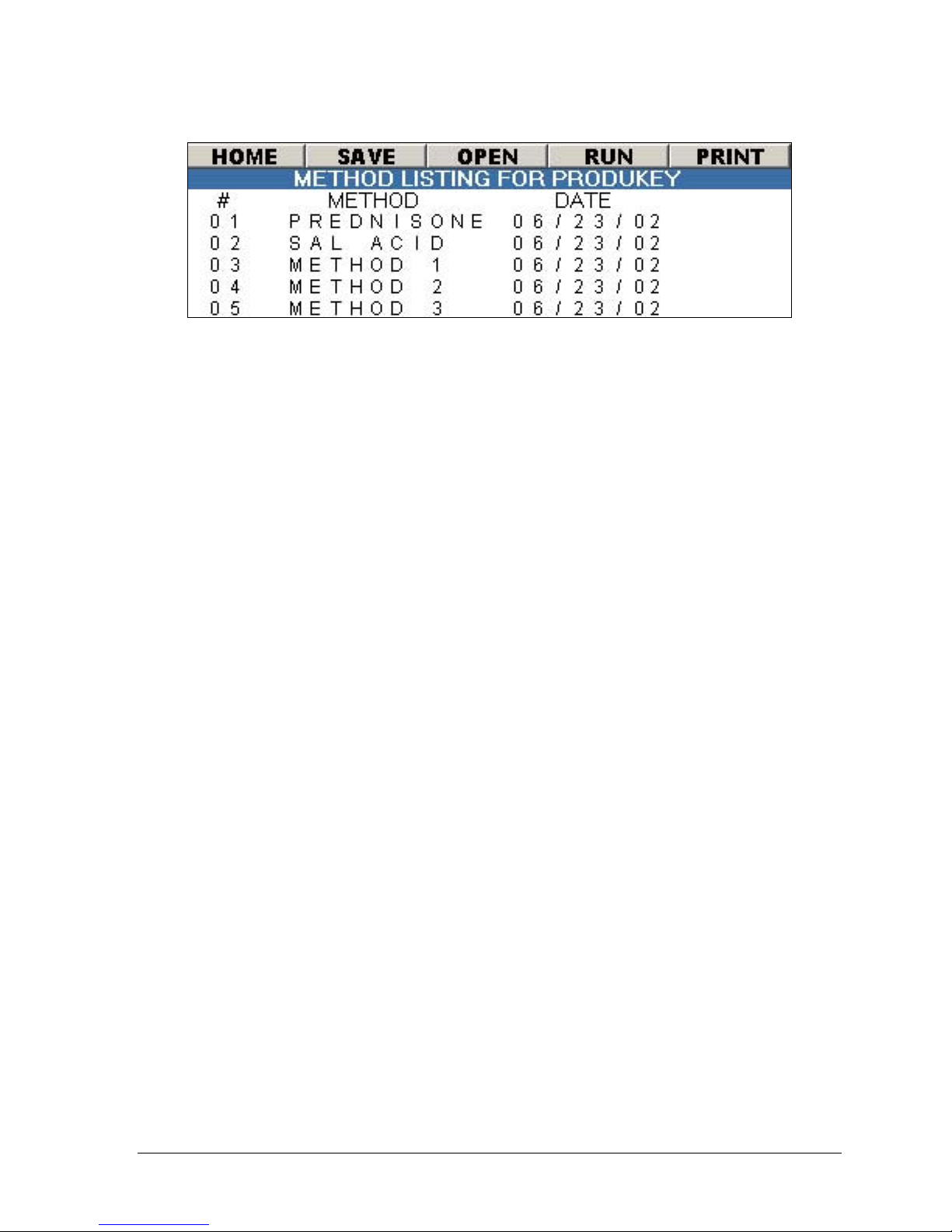
Chapter 3: Operation
3-37
Figure 3-32: produKEY Method Listing Screen
Viewing Methods on the produKEY
1. Insert the produKEY into the slot to the right of the control keypad. Turn
the key clockwise 1/4 turn. The unit will produce an audible beep.
2. The screen shown in Figure 3-32 will be displayed.
3. Highlight the method from the list and select ENTER from the keypad.
4. Highlight the OPEN menu bar item and select ENTER.
Saving a Method from the produKEY to the Instrument
1. Insert the produKEY into the slot to the right of the control keypad. Turn
the key clockwise 1/4 turn. The unit will produce an audible beep.
2. The screen shown in Figure 3-32 will be displayed.
3. Highlight the method from the list and select ENTER from the keypad.
4. Highlight the SAVE menu bar item and select ENTER.
Running a Method from the produKEY
The procedure below describes how to run a method directly from the produKEY
without saving the method to the instrument.
1. Insert the produKEY into the slot to the right of the control keypad. Turn
the key clockwise 1/4 turn. The unit will produce an audible beep.
2. The screen shown in Figure 3-32 will be displayed.
3. Highlight the method from the list and select ENTER from the keypad.
4. Highlight the RUN menu bar item and select ENTER.
Operation Manual: Evolution Series
Page 75

Chapter 3: Operation
3-38
Deleting Methods from the produKEY
1. Insert the produKEY into the slot to the right of the control keypad. Turn
the key clockwise 1/4 turn. The unit will produce an audible beep.
2. The screen shown in Figure 3-32 will be displayed.
3. Highlight the method from the list and select ESC/DELETE from the keypad.
Printing a Method from the produKEY
1. Insert the produKEY into the slot to the right of the control keypad. Turn
the key clockwise 1/4 turn. The unit will produce an audible beep.
2. The screen shown in Figure 3-32 will be displayed.
3. Highlight the method from the list and select ENTER from the keypad.
4. Highlight the PRINT menu bar item and select ENTER.
Using a Premiere 5100 produKEY
It is only possible to read from a Premiere 5100
produKEY (a method cannot be written to the key).
The Evolution is capable of utilizing existing produKEYs that were previously used
on the Premiere 5100 Dissolution System.
1. Insert the produKEY into the slot to the right of the control keypad. Turn
the key clockwise 1/4 turn. The unit will produce an audible beep.
2. The screen shown in Figure 3-32 will be displayed.
3. Follow the above procedures for saving, opening, running and printing
methods.
Using the calKEY
The Evolution Dissolution System comes with a calKEY that is configured at Distek's
factory with the unit's original calibration data. In the case of a failure where the
calibration data is lost, the unit can easily restore its calibration data to the
factory settings.
Operation Manual: Evolution Series
Page 76

Chapter 3: Operation
3-39
Storing Calibration Data
The following procedure describes how to save current calibration data to the
calKEY.
1. From the Main screen select SYSTEM CONFIG.
2. From the SYSTEM screen select CALIBR.
3. Enter the valid password.
4. Insert the calKEY into the slot to the right of the control keypad. Turn the
key clockwise 1/4 turn. The unit will produce an audible beep.
5. The following message will be displayed:
UPDATE CALIBRATION
DATA FROM CALKEY.
Select NO.
6. A screen displaying the various calibration methods will be displayed
(Probe, TempChek or Reference). Select the appropriate method.
7. Select the calKEY button located on the bottom of screen.
8. The following message will be displayed:
CONFIRM SAVING OF CALIBRATION
DATA TO THE CALKEY.
Select YES.
Restoring Calibration Data
In case the calibration data is corrupted or lost, the following procedure describes
how to restore the data.
1. From the Main screen select SYSTEM CONFIG.
2. From the SYSTEM screen select CALIBR.
3. Enter the valid password.
4. Insert the calKEY into the slot to the right of the control keypad. Turn the
key clockwise 1/4 turn. The unit will produce an audible beep.
5. The following message will be displayed:
UPDATING CALIBRATION
DATA FROM THE CALKEY.
Select YES.
Operation Manual: Evolution Series
Page 77

Chapter 3: Operation
3-40
Printouts
The Evolution Series contains several types of printouts. The unit is capable of
printing real-time test reports, saved reports, InstaPrint, method settings, user
settings and calibration data. See Appendix E for sample printouts.
To configure printing simply connect a printer cable from the printer port located
on the side of the system to the printer. If multiple units will be sharing one
printer see Printer Sharing Configuration on page 3-9.
InstaPrint can be selected any time the heaters and RPM are enabled. The units
will printout applicable information depending on whether an AUTO test or
MANUAL test is running. Printouts are created by pressing the PRINT menu bar
item located on several screens throughout the user interface.
Serial Port Control
AA represents the unit address.
Command Response Function
[AA CONT:VESL:TEMP NNN] [NNN]
[AA CONT:VESL:TEMP X,NNN] [X,NNN] Set temperature (NN.N°C) for vessel X
[AA CONT:VESL:ELEM 'TYPE'] [PADDLE] or [BASKET]
[AA CONT:VESL:ELEM
X,'TYPE']
[AA CONT:VESL:VOL NNNN] [NNNN] Set volume (NNNN mls) for all vessels
[AA CONT:VESL:VOL X,NNNN] [X,NNNN] Set volume (NNNN mls) for vessel X
[AA CONT:VESL:STAT X, ON] [X,ON] Enable vessel X.
[AA CONT:VESL:STAT X, OFF] [X,OFF] Disable vessel X.
[AA CONT:VESL:ENBL
1234567]
[AA CONT:VESL:ELEM?] [PADDLE] or[BASKET] Report the stirring type for all vessels.
[AA CONT:VESL:ELEM? X] [PADDLE] or[BASKET] Report the stirring type for vessel X.
[AA CONT:VESL:TEMP?] [NNN]
[AA CONT:VESL:TEMP? X] [NNN]
[AA CONT:MOTO:SET NNNN] [NNNN] Set the RPM (NNNN).
[AA CONT:MOTO:STAT ON] [ON] Turn the motor on.
[AA CONT:MOTO:STAT OFF] [OFF] Turn the motor off.
[X,PADDLE] or [X,BASKET]
[!] Enable vessel 1, 2 3, 4, 5, 6 & 7.
Set temperature (NN.N°C) for all enable
vessels
Set stir type for all vessels, where 'TYPE' is
PADDLE or BASKET.
Set stir type for vessel X, where 'TYPE' is
PADDLE or BASKET.
Report the set point temperature (NN.NN°C)
for all vessels.
Report the set point temperature (NN.NN°C)
for vessel X.
Operation Manual: Evolution Series
Page 78

Chapter 3: Operation
3-41
Command Response Function
[AA CONT:MOTO:STAT?] [ON] or [OFF] Report the status of motor.
[AA CONT:MOTO:SET?] [NNN] Report the setting of RPM (NNN).
[AA CONT:HEAT:STAT ON] [ON] Turn the heaters on.
[AA CONT:HEAT:STAT OFF] [OFF] Turn the heaters off.
[AA CONT:TEST:ABORT] [!] Abort the current test.
[AA CONT:TEST:CLR] [!] Reset the delta.
[AA CONT:TEST:START] [!] Start the current activated method.
[AA MEAS:ALL] [a1,a2, ….a11]
[AA MEAS:RPM] [NNNN] Report RPM (NNN.N).
[AA MEAS:RPM:MAX] [NNNN] Report max RPM (NNN.N).
[AA MEAS:RPM:MIN] [NNNN] Report min RPM (NNN.N).
[AA MEAS:TEMP:AVG] [NNNN]
[AA MEAS:TEMP:CUR X] [NNNN] Report the current temperature of vessel X.
[AA MEAS:TEMP:MAX X] [NNNN] Report the max temperature of vessel X.
[AA MEAS:TEMP:MIN X] [NNNN] Report the min temperature of vessel X.
[AA MEAS:TEMP:MAX] [a1,a2, ….a7]
[AA MEAS:TEMP:MIN] [a1,a2, ….a7]
[AA SYST:DATE YYYY,MM,DD] [YY,MM,DD] Set the system date.
[AA SYST:TIME HH,MM,SS] [HH,MM,SS] Set the system time.
[AA SYST:DATE?] [YY,MM,DD] Report the current date.
[AA SYST:TIME?] [HH,MM,SS] Report the current system time.
[AA SYST:CAL?]
[AA SYST:ETIME?] [HH,MM] Report the elapsed time as hours and minutes.
[AA SYST:ADDR?] [AA] Report the address of the unit.
[AA SYST:SLEEP] [!] Puts the system in sleep mode.
[AA SYST:ADDR AA,PP,TT] [!] Set the addresses for the unit, printer and TCS
[AA SYST:PRNT:REQ BB] [PRNT DD]
[iiii,ssss,iiii,ssss,
…,iiii,ssss]
Report rpm, max rpm, min rpm, temp at V1,
V2 … V8.
Report the averaged temperature of all
enabled vessels
Report the max temperatures of vessels 1, 2 …
7.
Report the min temperatures of vessels 1, 2 …
7.
Report cal settings: intercept iiii and slop ssss
of each vessel.
The unit BB requests a printer service from unit
AA. Valid DD responses:
• 0: the request is allowed
• 1: the printer of the unit AA is off or
offline
• 2: the printer of the unit AA is out of
paper
• 3: the printer of the unit AA has an
error
• 4: the printer of the unit AA is busy.
Please wait
• 5: the unit AA doesn't have a local
printer
Operation Manual: Evolution Series
Page 79

Chapter 3: Operation
3-42
Command Response Function
Tell the unit BB to send a string to print.
[BB NEXT] [ssssss …..sssss]
[AA *IDN?]
[AA HCOP:IMM] [!] Print an instant report.
[AA PKGT:METH:HEAD
NNNNNNNNNNNNNNNN
HHHH MM
HHHH MM
DDD
S
TTT
RRR
iii
LLL
E
P
[AA PKGT:METH:SAMP l,
HHHH MM
HHHH MM
HHHH MM
HHHH MM
HHHH MM
HHHH MM
HHHH MM
HHHH MM]
[AA PKGT:METH:HEAD?]
[AA PKGT:METH:SAMP? l] [HHHH MM] Report the time points from l*8.
[6100/6300,SSSSSSS,PVRev
NNN]
[!]
[!]
[NNNNNNNNNNNNNNNN
HHHH MM]
Where sssss…sssss is a string (must be less than
81 characaters) to be printed.
Report the bath type, serial number (SSSSSSSS)
and Firmware Rev (NNN).
Set the header of a new method and saves the
header. The following variables can be set:
• Name: NNNNNNNNNNNNNNNN
• Test Length: HHHH (hours) MM (min.)
• IRPM Length: HH (hours) MM (min.)
• Delayed Drop: DDD seconds
• Report Switch: 0 (Off) or 1 (On)
• Temperature: TT.T°C
• RPM: RRR
• IRPM: iii
• Volume: LLL mls
• Enable Vessels: E: Bit X: Vessel X (1:
enable, 0: Disable)
• Stirrer Type: P for PADDLE & B for
BASKET
Set the list of sample time points (from i*8)
and saves the list. The max number of time
points of each command is 8. Total number of
time points of each method is 16
Report the method header.
Operation Manual: Evolution Series
Page 80

Chapter 4: Maintenance
4-1
4444 Maintenance
This chapter gives a very brief overview of properly maintaining the Evolution
Dissolution System. To ensure consistent performance a Preventive
Maintenance/Operational Qualification (PM/OQ) should be conducted periodically.
Contact Distek for more information.
General Information ................................................................. 4-2
Emptying the Water Bath & TCS (Evolution 6300 Only) ........................ 4-3
Removing the Water Bath (Evolution 6300 Only)................................ 4-4
Re-installing the Water Bath (Evolution 6300 Only) ............................ 4-5
Replacing the Water Bath and TCS Tubing (Evolution 6300 Only) ............ 4-5
Operation Manual: Evolution Series
Page 81

4-2
General Information
1. Unit should be cleaned periodically by wiping with a slightly damp cloth. Do
not use any harsh chemicals or detergents.
2. Electronics require no customer attention. In the event of a malfunction,
please call the factory before attempting any repairs.
3. Turn off unit and unplug power cord. Remove drive cover. Apply small
amount of Dow Corning High Vacuum Grease to top and bottom of both drive
belts. (This should be done every 6 months.) Replace cover. Drive motor
and bearings are permanently lubricated. Belt tension is factory adjusted.
4. Clean guide posts every three months with alcohol and wipe dry with clean
cloth or paper towel. Do not lubricate posts.
5. Temperature calibration probe should be cleaned off and stored in holder on
left rear side of drive unit when not in use.
6. Vessel support plate requires extra care. Do not allow acids or buffers to
remain on the plate for extended periods of time. WIPE THE PLATE CLEAN
AFTER USE. DO NOT SCRATCH OR SCORE PAINTED SURFACE.
7. TCS Fuse Replacement:
110V Fast Blow 5x20mm – 8A 250V
230V Fast Blow 5x20mm – 5A 250V
Chapter 4: Maintenance
Do not clean plastic and rubber parts with organic
solvents.
Operation Manual: Evolution Series
Page 82
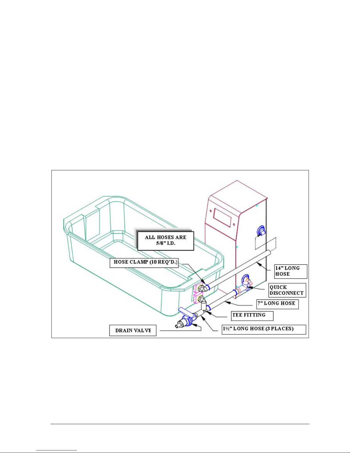
Chapter 4: Maintenance
4-3
Emptying the Water Bath & TCS (Evolution 6300 Only)
1. Turn the unit off.
2. Attach the drain tube to the end of the drain valve (black & orange fitting,
see Figure 4-1).
3. Place drain tube into a large bucket.
4. Open valve to drain media from the bath.
5. Once all the media has been drained disconnect the CPC quick connect
fitting on the entry port of the TCS.
6. Disconnect the top tube on the exit port of the TCS.
7. Empty the remaining media from the TCS by turning the unit upside down.
8. Remove the CPC fitting and tube from the exit port and empty the
remaining media.
9. Wipe the bath clean of remaining media.
Operation Manual: Evolution Series
Figure 4-1: TCS Connections
Page 83
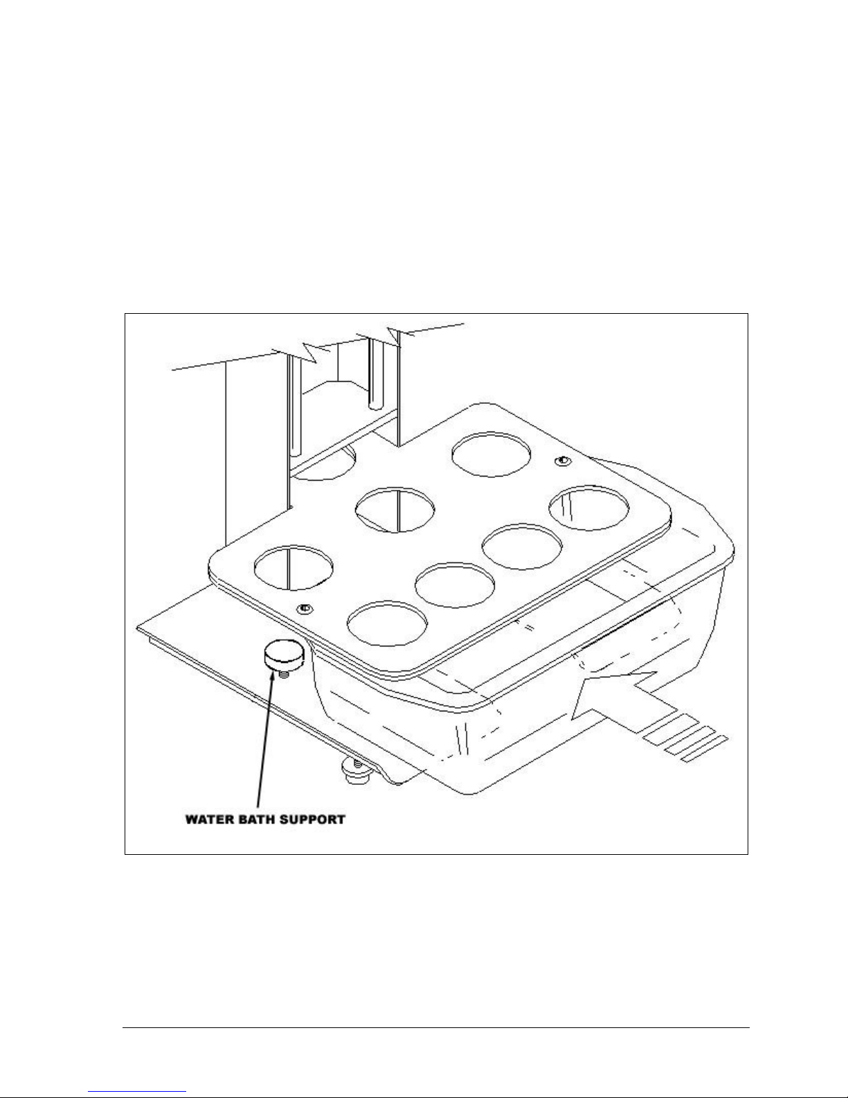
Chapter 4: Maintenance
4-4
Removing the Water Bath (Evolution 6300 Only)
1. Drain the water bath as described in the previous section.
2. Lower the water bath supports (see Figure 4-2) to its lowest position.
3. Push down the four bath corners to free it from the vessel plate.
4. Loosen the thumbscrew and turn the "bath lock" plate located on the front
of the vessel plate to an up position.
5. Remove the bath.
Operation Manual: Evolution Series
Figure 4-2: Water Bath Removal
Page 84

Chapter 4: Maintenance
4-5
Re-installing the Water Bath (Evolution 6300 Only)
Do not over-tighten supports. The foam seal strip under
the vessel plate should not be compressed any thinner
than 3/16" if possible.
1. Lower the water bath supports (see Figure 4-2) to their lowest point.
2. Slide the water bath into position and center it under the vessel support
plate.
3. Raise the supports until the water bath lip makes good contact with the seal
under the vessel support plate.
4. Return the "bath lock" plate to a down position and tighten the thumbscrew.
5. Connect hoses to TCS as shown in Figure 4-1.
6. Tighten all hose clamps.
7. Follow the procedures described in the Filling the Water Bath and Priming
the Pump on page 2-8 to fill the water bath and prime the TCS.
Always recheck the level after installing and filling the
water bath.
Replacing the Water Bath and TCS Tubing (Evolution 6300
Only)
The tubing connecting the Water bath and TCS should be replaced as needed.
With routine unit usage the tubing can get very dirty, thus requiring replacement.
Contact Distek to obtain a tubing replacement kit. The following procedure
describes how to change the tubing lines.
Operation Manual: Evolution Series
Page 85
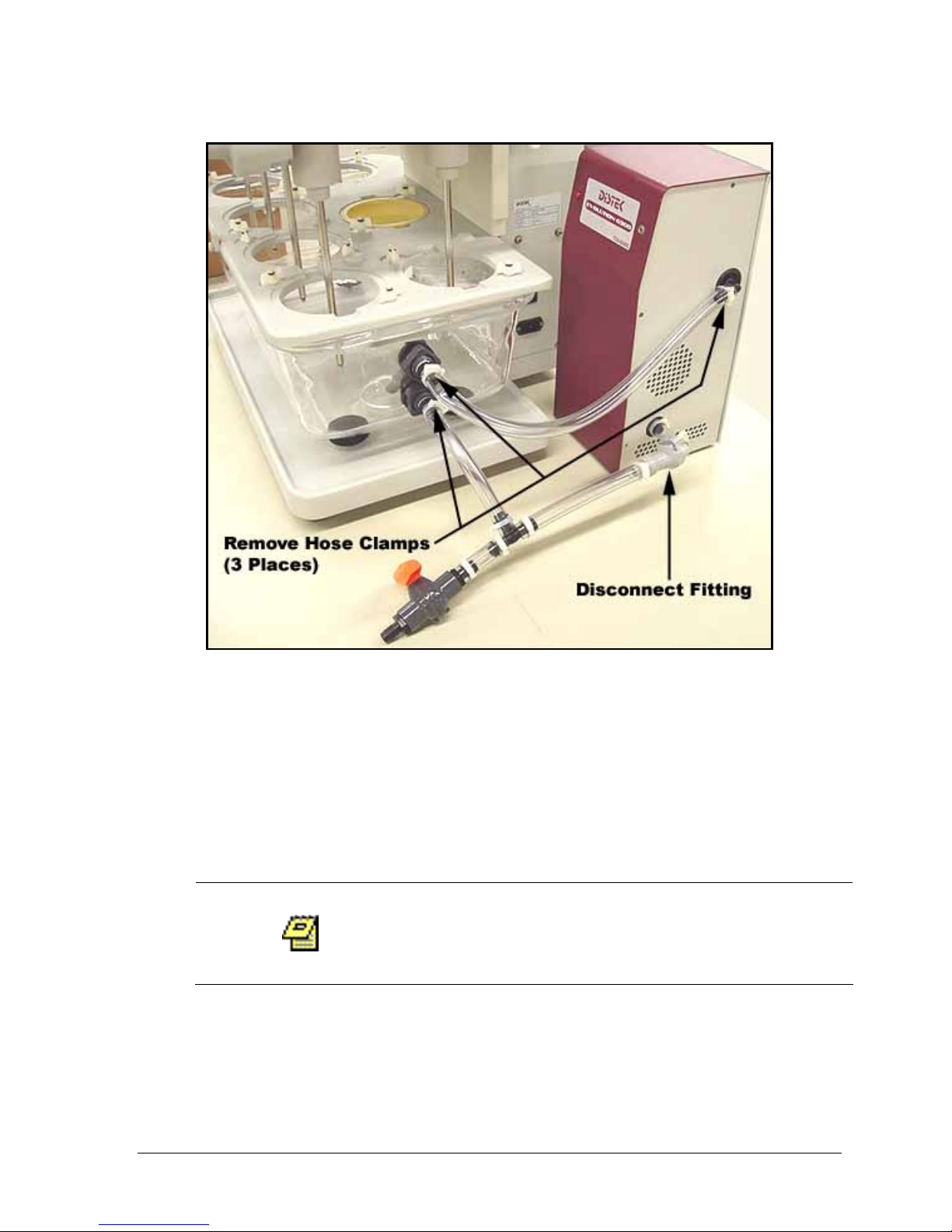
Chapter 4: Maintenance
4-6
Figure 4-3: Tubing Replacement Diagram
1. Remove the 3 tube clamps with pliers (see Figure 4-3).
2. Remove the 3 tubes from the fittings.
3. Disconnect the CPC fitting by pressing the dark grey button located on the
fitting (see Figure 4-3).
4. Connect the new tubing as shown in Figure 4-3.
5. Attach the 3 hose clamps using pliers.
Upon completion the TCS should be tested to ensure
there are no leaks. This is done by simply running the
TCS.
Operation Manual: Evolution Series
Page 86

5-1
5555 Troubleshooting
This chapter provides troubleshooting information to identify the most common
problems and their solution.
Troubleshooting ...................................................................... 5-2
Error Messages....................................................................... 5-15
Warning Messages ...................................................................5-17
General Messages ................................................................... 5-18
Service................................................................................ 5-19
Operation Manual: Evolution Series
Page 87
5-2
Troubleshooting
Before performing any procedure in this section, please
disconnect AC power from the unit.
Improper servicing or adjustment practice can cause
equipment failure or serious physical injury. This
equipment must be adjusted and serviced by qualified
electrical maintenance personnel who are familiar with
the construction and operation of the equipment and
the hazards involved. Take diligent care during
adjustment. All exposed points on the control circuit
boards are electrically hot with respect to earth ground.
HIGH VOLTAGE IS EXPOSED WHEN THE LOWER REAR
PANEL IS OPENED ON THE SYSTEM. Dangerous voltages
exist on the circuit boards when powered. Disconnect
AC power from the unit while troubleshooting. Be alert.
High voltage can cause serious or fatal injury.
The Evolution 6100 and TCS are supplied with proper
heaters and settings for the specified operating voltage
(see label for information). Do not attempt to convert
unit to another power supply without contacting the
factory first!
Operation Manual: Evolution Series
Page 88

5-3
Display/Keypad
PROBLEM POSSIBLE SOLUTION
LCD DISPLAY
Blurred display
Horizontal line
across the LCD
display
No display
Scrambled
LCD screen
Adjust display
contrast
Display cable Check the ribbon cable that goes from
LCD display Make sure that the display assembly is
Stage board Check that all socket chips are inserted
Display contrast Locate and adjust by turning the multi-
Display cable Check the ribbon cable that goes from
LCD display Make sure that the display assembly is
Display contrast Locate and adjust by turning the multi-
Display Cable Check the ribbon cable that goes from
LCD display Make sure that the display assembly is
Stage board Check that all socket chips are inserted
Power Supply
LCD display
Stage board
Locate and adjust by turning the multiturn potentiometer on the stage board.
the LCD connector to the stage board for
any loose wires or crimps.
mounted securely on the bezel.
Replace the LCD display.
properly.
Note: Make sure you do not bend the
leads when removing and reinstalling the
chip.
turn potentiometer on the stage board.
the LCD connector to the stage board for
any loose wires and crimps.
mounted securely on the bezel.
Replace the LCD display.
turn potentiometer on the stage board.
the LCD connector to the stage board for
any loose wires or crimps.
mounted securely on the bezel.
Replace the LCD display.
properly.
Note: Make sure you do not bend the
leads when removing and reinstalling the
chip. Replace the stage board if
necessary.
Cycle the main power off for at least 1
minute then turn it on again.
Check the ribbon cable that goes from
the LCD connector to the stage board.
Make sure that the display assembly is
mounted securely on the bezel.
Check that all socket chips are inserted
properly.
Note: Make sure you do not bend the
leads when removing and reinstalling the
chip.
Operation Manual: Evolution Series
Page 89

5-4
Display/Keypad
PROBLEM POSSIBLE SOLUTION
DRIVE MOTOR
LED DISPLAY
Shaft not
rotating-unit
heats
properly
Shaft rotatenot heating
properly
LED display
not scrolling/
locking up
No LED
display
Some LED
display digits
missing
Fuse
Cable
connectors
Re-cycle power
LCD display
Stage board
LED display
cable
Cabling
Connection
LED board
Interface board
LED display
cable
LED display
(seven
segment)
LED display
board
Interface board Replace the interface board (5150).
LED display
cable
LED display
LED board
Interface board Replace the 5150 interface board that
Check if the 0.5 amp fuse located on the
5151 PCB is blown.
Replace is needed.
Check drive motor connection on 5151
PCB at location “J6” (see figure 3) for
loose wire connection or damage pins.
Repair as necessary.
Check motor drive connection on the
drive motor itself for loose wire
connection or damaged pins.
Turn instrument off.
Wait approximately 2 minutes and
restart unit.
Make sure that the display assembly is
mounted securely on the bezel.
Replace the LCD display.
Check that all socket chips are inserted
properly.
Note: Make sure you do not bend the
leads when removing and reinstalling the
chip.
Replace the stage board if necessary.
Check the LED cable going from the 5150
board to the LED board (5104) for any
loose wires on the crimp connector.
Check wiring from the PC board to the
5154 (stage board).
Replace the 5104 LED board display.
Replace the 5150- interface board that
causes the LED board not to function.
Check the ribbon cable that goes from
the LED connector to the 5150 board for
any loose wires or crimps.
Check for any loose or shorted
connection on the LED display board.
Replace the LED display board.
Check the LED cable going from the 5150
board to the LED board (5104) for any
loose wires on the crimped connector.
Replace the LED seven-segment display if
necessary.
Replace the 5104 LED board display.
causes the LED board not to function
properly.
Operation Manual: Evolution Series
Page 90
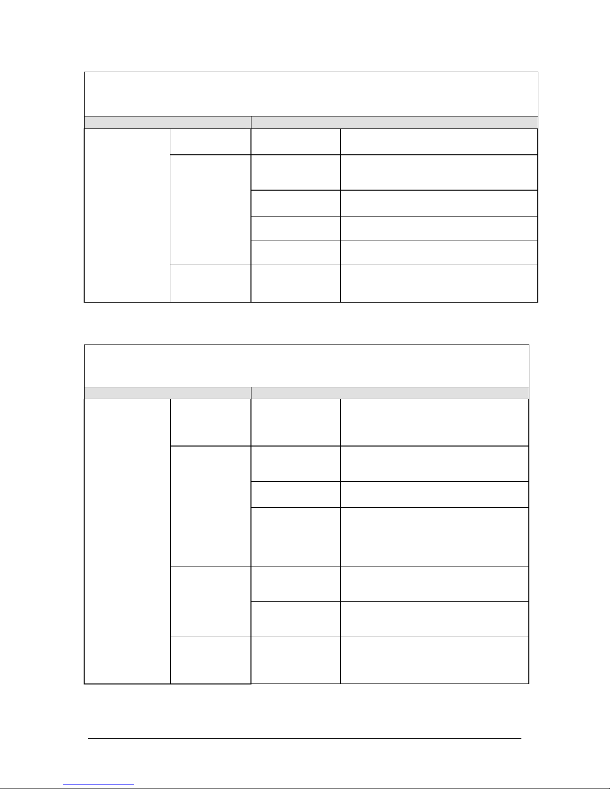
5-5
Display/Keypad
PROBLEM POSSIBLE SOLUTION
KEYPAD
Not heat light
LED indicator
indicator
Not
responding
Keypad
connection
Cabling
Connection
Stage board
Keypad
No stir light
LED indicator
indicator
when pressed
Power Supply
PROBLEM POSSIBLE SOLUTION
AC SUPPLY
Main circuit
keeps
tripping
No main
power
No low
voltage ac
(secondary)
from the
transformer
Power switch
keeps
tripping
Short circuit on
the unit
Underrated
main circuit
Main circuit
breaker
Main outlet
No power
I/O board
voltage selector
Short circuit on
the unit
Defective LED. Replace the keypad
overlay.
Check that the keypad connector is
securely inserted into stage board J11
connector.
Check wiring from the PC board to the
5154 (stage board).
Replace the 5154-stage board that
causes the keypad to malfunction.
Replace the keypad membrane for
probable short on the circuit.
Defective LED.
Replace the keypad overlay.
Check the unit for any shortages
starting from the power switch,
transformer, wiring and the system
circuit boards.
Check that the circuit breaker for that
particular line outlet is not underrated
as specified.
Check that the circuit breaker for that
particular line outlet is turned on.
Check that the unit is plugged in a
regular outlet without ground fault
interrupters (this will cause the outlet
to trip during heating due to overload).
Check with an electrician.
Measure if there is input voltage
coming into the transformer primaries
(115v or 2202v).
Check that the transformer wirings are
securely fastened into the I/O
connector.
Check the unit for any shorts starting
from the power switch, power supply,
transformer, wiring and the system
circuit boards.
Operation Manual: Evolution Series
Page 91

5-6
Power Supply
PROBLEM POSSIBLE SOLUTION
Underrated
power switch
DC SUPPLY
No +5V
No +12V
No +6V
No -5V
No high
voltage (HV)
Switcher Power
Supply
Wiring harness
Interface board
Switcher Power
Supply
Wiring harness
Interface board
Transformer
secondary
Wiring harness
Interface board
Check that the power switch is rated
for that particular unit (see
Specification section in Chapter 1).
Measure the output voltage coming
from the power supply.
Check that the wiring is securely
connected into the power supply
terminals.
Also, check the connector that supplies
the interface board (5150) for any
loose connections.
Replace the defective interface board
(5150).
Measure the output voltage coming
from the power supply at +12V and 12V.
Check that the wiring is securely
soldered into the power supply
terminals.
Also, check the connector that supplies
the interface board (5150) for any
loose connections.
Replace the defective interface board
(5150).
Measure if there is output voltage
coming out the transformer secondary.
If there is no AC voltage coming out of
the secondary, replace the
transformer.
Check that the transformer wiring is
securely soldered into the transformer
terminals.
Also check the connector that supplies
the motor/heater board for any
connections.
Replace the defective interface board
(5150).
Operation Manual: Evolution Series
Page 92

5-7
Heating/Speed
PROBLEM POSSIBLE SOLUTION
HEATERS
“Abnormal
Heating
Profile”
No heat
Triacs
Heaters
Calibration
Volume settings
Motor/heater
board
Vessels
Stirring element
Probe
Power
Stage board
Triacs
Heaters
Program
disabled heater
Check for any defective triacs that
stays off all the time when heaters
are enabled.
Check for heater unplugged or any
loose wiring from the heater
especially where the connectors
meet.
Check the resistance of the heater(s)
is not infinite or open.
Check and verify the calibration of
the unit. Check the low calibration
at room temperature and the high
calibration between 37 to 40 degrees
centigrade.
Perform calibration if necessary.
Check that a specific vessel
position(s) is set to the right volume
setting (this can be done through
manual parameter settings or auto
test).
Replace the defective motor/heater
board.
The vessel is empty. Cool & fill with
liquid.
Stirring element is out of vessel;
lower and stir.
Vessel probe may have failed; test
and replace.
Turn off main power switch, wait 10
seconds and turn back on to reset.
Stage board failure. Replace board.
Check for any defective triac(s) that
stays off all the time when heaters
are enabled. Replace the defective
triac(s) if found faulty.
Check for heater unplugged or any
loose wiring from the heater
especially where the connectors
meet.
Check that the resistance of the
heater(s) is not infinite or open.
Check that a specific vessel
position(s) is enabled (this is done
through manual parameter settings or
auto test).
Note: An asterisk symbol next to
vessel number (*1) means vessel #1 is
on.
Operation Manual: Evolution Series
Page 93

5-8
Heating/Speed
PROBLEM POSSIBLE SOLUTION
Motor/heater
board
Slow heating
on one or
more vessel
position
When
heat/start
key pressedheat
indicator
lights up
momentarilyheater will
not turn on
DRIVE MOTOR No stirring
Triacs
Heaters
Programmed
volume settings
Motor/heater
board
Height switch
Wiring
Motor fuse
Height switch
Motor cable
wiring harness
Replace the defective motor/heater
board.
Check for any defective triacs that
stays off all the time when heaters
are enabled.
Check for any loose wirings from the
heaters harness especially where the
connectors meet.
Check that the resistance of the
heaters(s) is not infinite or open.
Check that a specific vessel
position(s) is set to the right volume
setting (with 500mls settings only the
lower part of the heater will be
enabled).
Change the volume settings through
manual parameter settings or auto
test.
Replace the defective motor/heater
board if necessary.
Check that the height switch is
engaged when the drive head is
lowered.
Adjust the switch position until it
triggers the switch with the cylinder
of the gas spring.
Check that the wiring of the height
switch is intact and the connector
end is plugged into J4 of the
interface PCB (5150).
Check that the fuse (F5) for the
motor on the motor/heater board is
not faulty.
Replace if found faulty.
Check that the height switch is
engaged when the drive head is
lowered.
Check that the wiring of the height
switch is intact and the connector
end is plugged into J4 of the
interface PCB (5150).
Check that the cable is intact and
make sure all connectors are plugged
into their respective mates from the
drive motor to the motor/heater
board.
Operation Manual: Evolution Series
Page 94
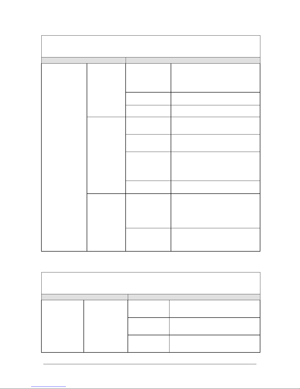
5-9
Heating/Speed
PROBLEM POSSIBLE SOLUTION
Defective drive
motor
No high voltage
supply
Motor board
Speed goes
to maximum
Motor cable
wiring harness
speed
Magnetic pick
up gap
Magnetic pick
up
Motor/heater
board
Stir key
Height switch
pressedindicator
lights up
momentarilydrive motor
will not turn
Wiring
on.
*I/O Communication
PROBLEM POSSIBLE SOLUTION
PRINTER No printout
I/O cable
Printer cable
Printer
Check the cable for any faulty
connections.
Replace the cable if necessary.
Check the IEEE printer cable for any
faulty connections especially with
bent pins.
Make sure that the printer is on and
has enough paper.
Set the printer’s carriage return to
Check the drive motor for any shorts
and faulty wiring.
When the drive motor is turned by
hand the rotation should be smooth
and without binding.
Refer to problem “No high voltage”.
Replace the defective motor/heater
board.
Check that the cable is intact and
make sure all connectors are plugged
into their respective mates.
Check that the distance between the
magnetic pick-up and the rotating
gear is at 0.008 inch.
Check that the magnetic pick-up is
securely fastened with the bracket.
Check the magnetic pick-up shorts or
faulty wiring.
Replace if found defective.
Replace the defective motor/heater
board.
Check that the height switch is
engaged when the drive head is
lowered.
Adjust the switch position until it
touches the cylinder of the gas
spring.
Check that the wiring of the height
switch is intact and the connector
end is plugged into J4 of the
interface PCB (5150).
Operation Manual: Evolution Series
Page 95

5-10
*I/O Communication
PROBLEM POSSIBLE SOLUTION
enable. This can be done through the
printer’s software.
Under “SYSTEM SETUP” make sure
that the printer settings are
configured properly. ('L' for local or '#'
for Printer Sharing.)
Check the board for any faulty or
short connections.
Replace the I/O board if necessary.
Check the cable for any faulty
connections.
Check the RS232 cable for any faulty
connections especially bent pins.
Make sure that the system address is
set right.
Make sure that the setting of the
controller matches the systems
protocol. Use COM1-COM4 at 9600baud rate.
Check the board for any faulty
connections.
Replace the I/O board if necessary.
Check the cable for any faulty
connections.
Check the RS485 cable for any faulty
connections especially bent pins.
Make sure that the system address is
set right.
Make sure that the setting of the
controller meets the systems protocol.
Use COM1-COM4 at 9600-baud rate.
Check the board for any faulty
connections. Replace the I/O board if
necessary.
RS232 No
communication
(handshaking)
RS485 No
communication
Program
setting
I/O board
I/O cable
RS232 cable
Systems
address
PC or Master
controller
I/O board
I/O cable
RS485
System
address
PC or master
controller
I/O board
Operation Manual: Evolution Series
Page 96
5-11
Temperature, abnormal display
PROBLEM POSSIBLE SOLUTION
DISPLAY Temperature
seems
locked/not
changing
RTDs/CalProbe Abnormal
display
reading
+6 volts dc
not present
-5 volts dc
not present
RTD wiring
harness
A/D board
RTD
RTD cable
harness
A/D board
Refer to no +6 volts dc.
Refer to no -5 volts dc.
Check the harness for any faulty wiring
and connections.
Replace the A/D board.
Check the RTD(s) for any shorts or
higher resistance readings.
Check the harness for any faulty
connections.
Replace the A/D board.
Calibration
PROBLEM POSSIBLE SOLUTION
PROBE No response from
calibration probe
Cal Probe
RTD wiring
harness
A/D board
Check the calibration probe for any
shorts.
Check the harness for any faulty
connections.
Replace the A/D board.
Mechanical
PROBLEM POSSIBLE SOLUTION
BATH LEVEL Level
Leveling feet
Rear
stabilizers
By using the bubble level as a
guide, level the unit from front to
back and side to side by adjusting
front leveling feet under
instrument base.
Adjust rear stabilizers so they just
barely touch the bench.
Chapter 5: Troubleshooting
Operation Manual: Evolution Series
Page 97

5-12
Mechanical
PROBLEM POSSIBLE SOLUTION
SHAFT
RTD shafts RTD shafts
WOBBLE/RUNOUT
SHAFT CENTERING Spindles
Spacers and
Inserts
Adjustments
With the unit at its operating
position (paddles or baskets) use a
run out gauge to validate the
shaft wobble.
Mount the gauge base with a
clamp on the vessel support plate
(next to the shaft to be checked).
Move the tip of the gauge until it
contacts the shaft tolerably.
Raise the drive head until the tip
of the gauge is just less than 1
inch above the apparatus.
Rotate a spindle that is not under
test manually until you reach the
high-end deflection of the gauge’s
readout.
Gradually push the shaft with your
thumb near the meter shaft, away
from the gauges adjustable tip.
Start stirring at 25 rpm and check
the shaft wobble.
Do this until you meet the
specifications.
Check the spacers and inserts for
defects.
Replace if necessary.
Attach CenterChek as per
instruction on the position in
question.
Rotate a spindle that is not under
test manually.
Note the whole deflection of the
CenterChek.
Rotate the gauge until you reach
the high-end deflection of the
gauge’s pointer (counter
clockwise movement) then stop
the rotation.
Open the drive assembly cover.
Chapter 5: Troubleshooting
Operation Manual: Evolution Series
Page 98

5-13
Mechanical
PROBLEM POSSIBLE SOLUTION
Loosen the screws (big) slightly
until you get a slight movement of
the spindle in question.
Loosen or tighten one of the
setscrews until you can set the
pointer of the gauge between the
low and high deflection of the
meter.
Carefully start tightening the big
screws making sure that the
pointer of the gauge only moves
slightly.
Refer to “Shaft wobble/run out”.
Replace non-Distek vessels (Distek
vessels have a tighter inside
diameter tolerance).
Check the installation of the
centering arm making sure that
the plastic nylon post is flush with
the arm.
Replace if centering arm is broken
or has defects.
Refer to manual for “Paddle and
Basket Height Adjustment”.
Make sure that when locking the
shaft collars the shaft does not
move (slightly push down the
shaft while locking the collars).
Replace non-Distek vessels (Distek
vessels have a tighter inside
diameter tolerance).
Adjust the tension of the brake
assembly.
Clean drive post.
Use cloth dampened with alcohol
and wipe dry.
Replace if gas spring is found
defective (pressure leakage).
Check for drive belts tension.
Adjust if necessary.
Check the drive motor’s
conductive brushes for wear.
Replace the brushes if necessary.
APPARATUS
HEIGHT
ADJUSTMENT
DRIVE HEAD
MOVEMENT
DIFFICLUT TO
RAISE AND LOWER
NOISE IN DRIVE
ASSEMBLY
Shaft
Shaft
wobble/run out
Vessels Non-Distek
vessels
Vessel
Mounting
centering arm
assembly
Centering
arm
Paddle and
Height block
basket height
Shaft collars Locking
collars
Vessels Non-Distek
vessels
Brake tension Tension
Drive posts Guide posts
Gas Spring Gas Spring
Drive belts Drive belts
tension
Drive motor Brushes
Chapter 5: Troubleshooting
Operation Manual: Evolution Series
Page 99

5-14
Mechanical
PROBLEM POSSIBLE SOLUTION
Inspect the idler wheels especially
the bearings for any sign of wear.
Lubricate the bearings if
necessary.
Replace the idler wheel assembly.
Inspect the pulleys for any cracks
that may cause the setscrews to
loosen up. This will cause the
pulley to rotate around the
spindle shaft.
Check drive belts tension.
Adjust if necessary.
Lubricate the drive belts with
vacuum grease.
Replace the drive belts if
necessary.
Check the drive motor’s
conductive brushes for wear.
Replace the brushes if necessary.
Inspect idler wheels especially
bearings for any sign of wear.
Lubricate bearings if necessary.
Replace idler wheel assembly.
Make sure that there are no units
that can produce excessive
vibration when they are turned on
(filtration systems, shakers, etc.).
Inspect the pulleys for any cracks
that may cause the setscrews to
loosen up (this will cause the
pulley to rotate around the
spindle shaft).
Replace cracked or defective
pulleys.
EXCESS VIBRATION
Idler wheels Idler wheels
Pulleys Pulleys
Drive belts
Drive belts
tension
Lubrication
Drive belts
Drive motor Brushes
Idler wheels Idler wheels
Other
equipment
Instruments
and
equipment
Pulleys Pulleys
Chapter 5: Troubleshooting
Operation Manual: Evolution Series
Page 100

Chapter 5: Troubleshooting
5-15
CANNOT ADD NEW USER.
ONLY A MANAGER CAN ADD
ONLY A MANAGER CAN
ONLY A MANAGER CAN
USER: USER_NAME
SYSTEM DOES NOT ALLOW
ONLY A MANAGER HAS
Error Messages
The following messages may appear on the front LCD display.
Message Possible Cause Solution
HI-CAL MEDIA TEMP IS TOO
LOW. INCREASE MEDIA TEMP
ABOVE XX°C.
LO-CAL MEDIA TEMP IS TOO
HIGH. DECREASE MEDIA
TEMP BELOW XX°C.
USER LIMIT HAS BEEN
EXCEEDED.
NEW USERS!
DELETE A USER!
MODIFY USER ACCOUNTS!
EXISTS. ENTER NEW
USERNAME.
SELF DELETION!
CALIBRATION PRIVELEGES.
The vessel temperature is
too low to perform a high
temperature calibration.
The vessel temperature is
too high to perform a low
temperature calibration.
Trying to add a new user
when the maximum number
of users has already been
reached.
A person with USER
privileges is logged into
the system. A USER does
not have correct access to
add users.
A person with USER
privileges is logged into
the system. A USER does
not have correct access to
delete users.
A person with USER
privileges is logged into
the system. A USER does
not have correct access to
modify users.
Attempting to add a user
with the same username
as an existing user.
The user was trying to
delete the login profile
that they are currently
logged in as.
A person with USER
privileges is logged into
the system. A USER does
not have correct access to
calibrate the system.
Increase media
temperature.
Decrease media
temperature.
Delete a user prior to adding
a new user.
Logout of system and
have a manager log in to
add a new user.
Logout of system and
have a manager log in to
delete a user.
Logout of system and
have a manager log in to
modify a user.
Enter a different
username.
You cannot delete a login
if it is currently being
used. Log out and log
back in using a different
user and then delete the
user.
Logout of system and
have a manager log in to
calibrate the system.
Operation Manual: Evolution Series
 Loading...