

Page 1
Soffit Application
Sound Enclosure
Addendum for Soffit Version
READ ALL INSTRUCTIONS BEFORE BEGINNING INSTALLATION
01-07 1
tel: 303.412.0399 www.displaydevices.com
fax: 303.412.9346 tech@displaydevices.com
5880 Sheridan Blvd., Arvada, Colorado 80003
Page 2
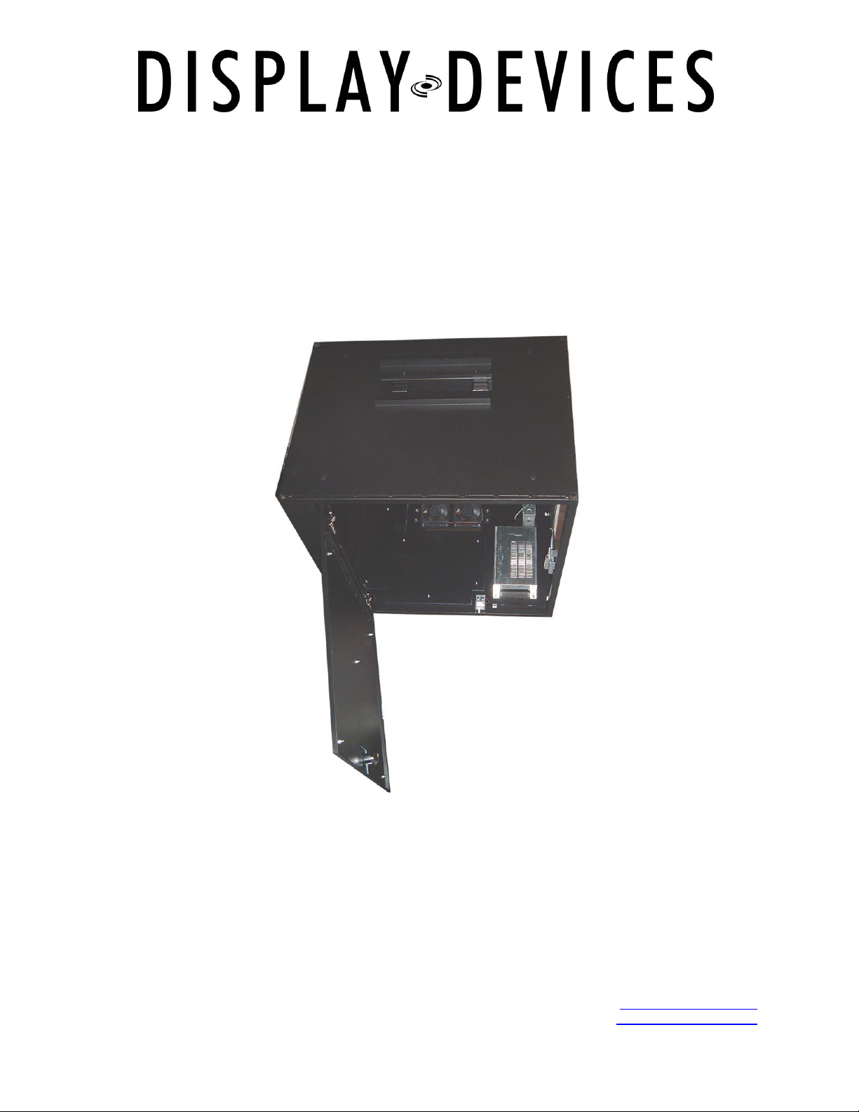
SE-B6/10 Soffit Series Sound Enclosures
Thanks for purchasing a Display Devices product. We‟re sure your customer will use this product for
years to come. Our products are designed to be maintenance-free saving you future service time. If you
experience any difficulties, please contact us at 303-412-0399. Thank you for your support.
This Sound Enclosure is designed to be built into a soffit to relocate projector noise to within a ceiling or
wall. Display Devices‟ projector lifts can be incorporated within this unit for easy service access. Sound
Enclosures work best when installed as part of a complete sound isolation system. For optimum sound
isolation we recommend the following:
Add intake and exhaust ducts to the enclosures‟ fire dampers – 6 feet or longer – this disperses
the sound away from the area it originates.
When built into a soffit, you will need to plumb the unit to an external fresh air source, plumb the
exhaust to another area away from the viewing room.
Air intake and exhaust are located on the sides of the unit creating airflow across the projector.
Tools required
Phillips-head screwdriver
Powered screwdriver with Phillips bit
¾”, 9/16” and 7/16” socket and open end wrenches
5” socket extension
Important
DO Ensure the ceiling structure is capable of holding at least four times the combined weight of the
enclosure and projector. This is a minimum requirement. Follow any local or state codes that apply to
your specific area. We recommend two people and a material lift for this installation.
1.) Install structural support for sound enclosure unit – utilize 3/8” (M10) threaded rod and
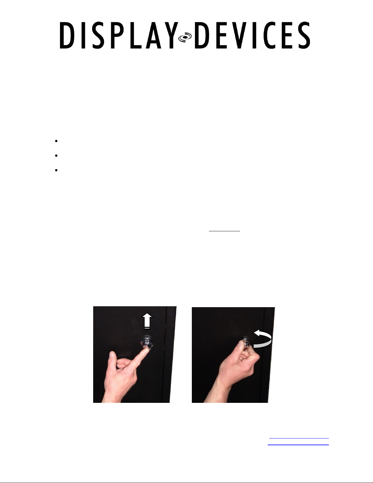
2.) The projector cavity is accessed through a swing down door. Be careful! The door is heavy
: Material Lift
hardware to bolt the unit into place. We recommend using a structural channel above the
unit for lateral positioning of the box.
and will swing down when the latch is released. Support the door when opening!
Push to unlock Twist to release
3.) Open bottom door to access mount holes. You may also remove the glass on the projection
port for access.
01-07 2
tel: 303.412.0399 www.displaydevices.com
fax: 303.412.9346 tech@displaydevices.com
5880 Sheridan Blvd., Arvada, Colorado 80003
Page 3

Threaded rod
Nut
Flat washer
Split lock washer
Flat washer
Nut
Sound Enclosure
Mounting rails with
pre-installed rods
4.) Raise the unit up on a material lift to the appropriate vertical height. Be sure to have a
sufficient amount of threaded rod to provide leveling room. Add hardware as follows for
leveling: above unit – nut/lock washer/flat washer; underside of unit – washer and nut - do
not tighten yet.
5.) Use a bubble level to level the unit front-to-back and side-to-side. Tighten hardware.
6.) To attach the fire dampers to the intake and exhaust ports use the enclosed Phillips-head
sheet metal screws.
7.) Add runs of ductwork on the intake and exhaust fire dampers. Addition of ducts disperses
the sound further away from the projector. Sound-isolating ductwork is recommended. If
additional sound dampening is desired, we recommend an auto sound insulation material.
8.) Mounting points for a projector mount or lift are pre-installed inside the top of the cavity. The
structural channel can be loosened and adjusted for the proper width of the mount or lift.
01-07 3
tel: 303.412.0399 www.displaydevices.com
fax: 303.412.9346 tech@displaydevices.com
5880 Sheridan Blvd., Arvada, Colorado 80003
Page 4

9.) Verify the mount position front-to-back and side-to-side. Adjust the position of the mount if
required. Front-to-back: loosen the (4) 3/4” bolts on the “L” brackets in the side Unistrut
channels. Move the mount/cross rails to the appropriate position and tighten the hardware in
the side channels. (THESE ARE UNISTRUT NUTS AND WILL TURN/UNLOCK WHEN
LOOSENED – BE SURE THEY ROTATE WHEN TIGHTENED AND LOCK INTO CHANNEL)
10.) Install mount/projector or lift/projector according to the manufacturer‟s procedure.
11.) Plumb AC power to the power supply. Remove a knock-out and secure with strain relief.
Power input is on the power supply with an IEC connector.
12.) Plug your projector into the switched power outlet inside on the power supply.
13.) Remove another knock-out to route your projector signal/control cables. Secure with strain
relief.
14.) Remove blue film from glass then position in projection port. Add top hold down strip and
(2) 14”-20 nuts. Tighten nuts until glass is snug between gaskets.
15.) Turn on the power supply, then turn on the projector and adjust your projected image to the
screen.
16.) See the temperature controller section below to set fan temperature settings.
17.) Finish soffit / wall around enclosure.
01-07 4
tel: 303.412.0399 www.displaydevices.com
fax: 303.412.9346 tech@displaydevices.com
5880 Sheridan Blvd., Arvada, Colorado 80003
Page 5

Switched AC
Unswitched AC
AC Input
RS232 Optional
Control Panel
Power Supply
Temperature Controller
Operation
The Programmable Cooling System provides two levels of fan control, an audible alarm, switched AC
power-down and displays the current temperature of the enclosure.
Factory presets: Fan set 1: 80°
Fan set 2: 90°
Alarm: 111°
Power off: 120°
To start operation, turn on the AC switch on the power supply. The controller may sound an alarm, and
the fans will turn on for 10 to 20 seconds. The system will then reset to a start state.
01-07 5
tel: 303.412.0399 www.displaydevices.com
fax: 303.412.9346 tech@displaydevices.com
5880 Sheridan Blvd., Arvada, Colorado 80003
Page 6

Programming: There are four parameters to program. Each is programmed in the same
sequence. The control panel has four pushbuttons labeled SELECT MENU, Cursor UP,
Cursor DOWN and SAVE. The associated Power Supply is provided with an IEC AC power
cord and On / Off switch.
LED Display: The LED display provides two rows of text. When the system is powered
up, the LED display will read “Display Devices” and “Current Temp (number).” The twodigit number indicates the current temperature. Pressing the SELECT MENU button will
provide access to different programmable functions. If buttons are not pressed, the
display will automatically reset to “Current Temp” display after approximately 30 seconds.
Programming Temperature Control Level One: Press the SELECT MENU button once
and the display will read “Set Fan Lev1 (number)”. This number indicates the
temperature at which the Control One fans will begin operation. The second row of text
will change between “Current Temp” and current system status. If current temp is higher
than programmed point for level 1 fans, the display will indicate “Fans On Level 1”. Press
the UP or DOWN button to select desired temperature for Control One fans. Press SAVE.
Programming Temperature Control Level Two: Press the SELECT MENU button to
display “Set Fan Lev2 (number)”. This number indicates the temperature at which the
Control Two fans will begin operation. Press the UP or DOWN button to select desired
temperature for Control Two fans. Press SAVE.
Programming Alarm Level: Press the SELECT MENU button to display “Set Alarm Lev.
(number)”. This number indicates the temperature at which the audible alarm will sound.
Press the UP or DOWN button to select desired temperature for Audible Alarm. Press
SAVE.
Programming Power Off: Pressing the SELECT MENU button again will show “Set
Power Lv”. This will provide removal of power from the switched AC outlet. Press the UP
or DOWN button to select desired temperature for removal of power at switched AC.
Press SAVE.
Selecting Temp. Standard: Pressing the SELECT MENU button again will show either
Fahrenheit or Celsius. Pressing the Up or Down button will change the temperature
format. Press SAVE.
01-07 6
tel: 303.412.0399 www.displaydevices.com
fax: 303.412.9346 tech@displaydevices.com
5880 Sheridan Blvd., Arvada, Colorado 80003
Page 7

Command
Description
Example
Q
Request Current Temperature
Q
Axxx
Set Fan Level 1
A078
Bxxx
Set Fan Level 2
B083
Cxxx
Set Alarm Level
C090
Dxxx
Set Power Cutoff Level
D100
Command
Description
Example
T xxx
Current Temperature
T 073
G
Fan Level 1 On
G
H
Fan Level 2 On
H
I
Alarm On
I
J
Power has been switched off
J
S (O,C)
Door Switch is Open/Closed
SO SC
M
Motion Sensor Tripped
M
K
Received Set command, Executed OK
K
X
Can not understand Command
X
Temperature Controller
OPTIONAL RS232 Interface
Hardware
Standard three pin hookup, 2,3,5, on DB9.
Baud rate 9600,N,8,1.
No handshaking.
Software
ASCII letters followed by a delimiter and carriage return (ASCII 13).
Commands from Host to Controller:
xxx-temperature Carriage Return (13)
Communications from Controller to Host:
xxx-temperature Carriage Return (13)
Notes:
All temperatures are in Fahrenheit.
Host program to convert to Celsius if required.
G,H,I,J are sent every few seconds when those levels have been tripped.
S is sent upon change of state.
M is sent upon shock sensor being tripped.
Temperature set range is from 1 to 190°, Fahrenheit.
Return temperature has a space after the „T‟ if positive, a – if negative.
Return temperature range is –140° to +190°.
01-07 7
tel: 303.412.0399 www.displaydevices.com
fax: 303.412.9346 tech@displaydevices.com
5880 Sheridan Blvd., Arvada, Colorado 80003
Page 8

Dual Fan Jumpers
Jumper #J3 & J4: leave jumpers in place for dual fan level control
01-07 8
tel: 303.412.0399 www.displaydevices.com
fax: 303.412.9346 tech@displaydevices.com
5880 Sheridan Blvd., Arvada, Colorado 80003
 Loading...