

Page 1
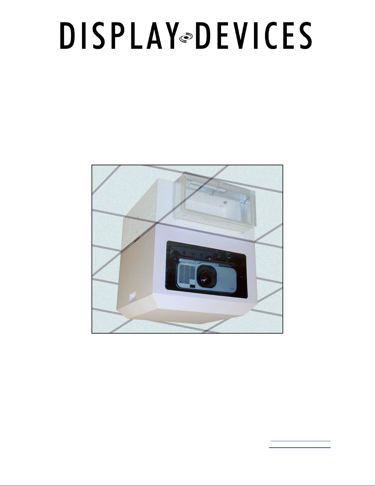
SE-B1
Sound Enclosure
Installation Manual
READ ALL INSTRUCTIONS BEFORE BEGINNING INSTALLATION
03/08 1
tel: 303.412.0399 www.displaydevices.com
fax: 303.412.9346 tech@displaydevices.com
5880 Sheridan Blvd., Arvada, Colorado 80003
Page 2
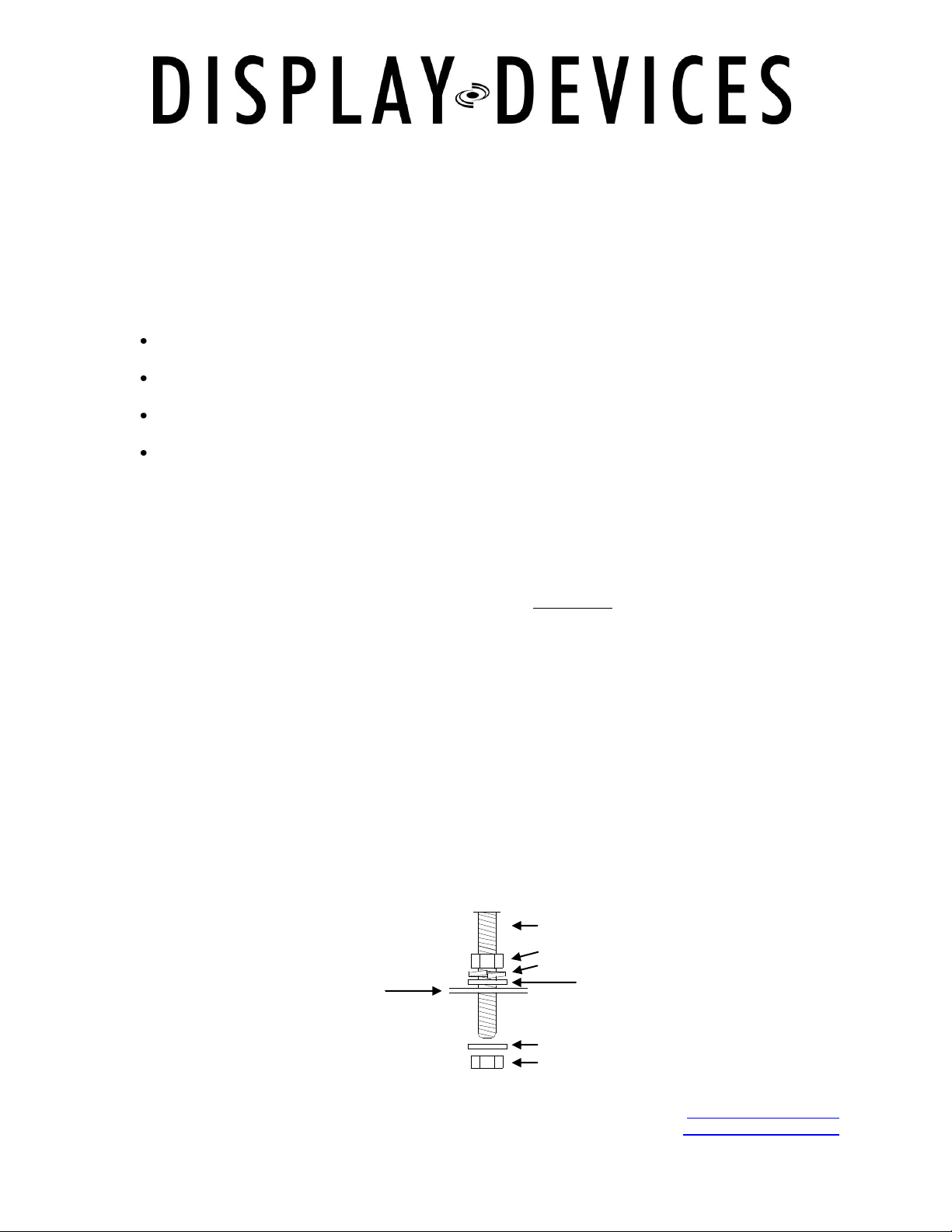
Threaded rod
Nut
Flat washer
Split lock washer
Flat washer
Nut
Sound Enclosure
SE Series Sound Enclosures
Thanks for purchasing a Display Devices product. We’re sure your customer will use this product for
years to come. Our products are designed to be maintenance-free saving you future service time. If you
experience any difficulties, please contact us at 303-412-0399. Thank you for your support.
The Sound Enclosure is designed to relocate projector noise to above a false ceiling. Sound Enclosures
work best when installed as part of a complete sound isolation system. For optimum sound isolation, we
recommend the following:
Add intake and exhaust ducts to the enclosures’ fire dampers – six feet or longer – this disperses
the sound away from the area it originates.
Insulate around the upper cavity on top of the ceiling tiles/media. Insulating this area increases
the barrier you create between the viewer and the noise source.
Plumb the unit to an external fresh air source, plumb the exhaust to another area away from the
viewing room.
Air intake is located on the projection port side.
Tools required
Phillips head screwdriver
Powered screwdriver with Phillips bit
¾”, 9/16” and 7/16” socket and open end wrenches
5” socket extension
Important:
DO Ensure the ceiling structure is capable of holding at least four times the combined weight of the
enclosure and projector. This is a minimum requirement. Follow any local or state codes that apply to
your specific area. We recommend two people and a material lift for this installation.
1.) Install structural support for sound enclosure unit – utilize 3/8” (M10) threaded rod and
2.) Remove access panel(s) to access mount holes (on the 2x2 configuration, one set of mount
3.) Raise the unit up on a material lift to the appropriate vertical height. The seam where the
: Material Lift
hardware to bolt the unit into place. We recommend using a structural channel above the
unit for lateral positioning of the box.
holes are accessible at the fan intake). You may also reach in through the projector port for
access.
upper and lower cavities are together in the closed position should be slightly above your
finished ceiling line. Be sure to have a sufficient amount of threaded rod to provide leveling
room. Add hardware as follows for leveling: above unit – nut/lock washer/flat washer;
underside of unit – washer and nut. Do not tighten yet.
03/08 2
tel: 303.412.0399 www.displaydevices.com
fax: 303.412.9346 tech@displaydevices.com
5880 Sheridan Blvd., Arvada, Colorado 80003
Page 3

4.) Use a bubble level to level the unit front-to-back and side-to-side. Tighten hardware.
5.) To attach the fire dampers to the intake and exhaust ports, use the enclosed Phillips-head
sheet metal screws.
6.) Add runs of ductwork on the intake and exhaust fire dampers. Addition of ducts disperses
the sound above the ceiling further away from the projector. Sound isolating ductwork is
recommended. If additional sound dampening is desired, we recommend an auto sound
insulation material.
7.) CAUTION: After the unit is hung in position, the lower portion of the enclosure will want to
lower due to gravity if not latched! Slide the lower portion of the unit down until it reaches
the stop point. Be sure to use pull evenly on the cavity handles. DO NOT TRY TO LOWER
OR OPEN ONLY USING ONE HANDLE.
8.) Verify the mount position front-to-back and side-to-side. Adjust the position of the mount if
required. Front-to-back: loosen the (4) 3/4” bolts on the “L” brackets in the side Unistrut
channels. Move the mount/cross rails to the appropriate position – tighten the hardware in
the side channels. (THESE ARE UNISTRUT NUTS AND WILL TURN/UNLOCK WHEN
LOOSENED – BE SURE THEY ROTATE WHEN TIGHTENED AND LOCK INTO CHANNEL). To
position the mount left to right inside the enclosure, loosen the (4) 7/16” bolts on the tilt axis.
With a long extension socket wrench, insert
9.) Loosen the (4) thumbscrews on the mount (only 2 if it is a small mount footprint). Slide the
mount back so the thumbscrews align with the large holes on the keyway slots. Remove the
mount interface plate.
10.) Align the mount interface plate to the projector and attach with the enclosed hardware.
11.) Install the projector with the attached interface plate. Raise thumbscrews up in the slots,
then slide the projector forward until it stops. Tighten the thumbscrews. Be sure to keep a
2” clearance from the projector’s exhaust fans to the wall of the unit.
12.) Plumb AC power to the power supply – remove a knock-out and secure with strain relief.
Power input is on the power supply with an IEC connector.
13.) Plug your projector into the switched power outlet inside on the power supply.
14.) Remove another knock-out to route your projector signal/control cables. Secure with strain
relief.
15.) Remove blue film from glass then position in projection port. Add top hold down strip and
(2) 14”-20 nuts. Tighten nuts until glass is snug between gaskets.
16.) Finish ceiling tile tightly up to sides of upper box. Use insulating materials above ceiling tile to
isolate sound.
17.) Turn on the power supply, then turn on the projector and adjust your projected image to the
screen.
03/08 3
tel: 303.412.0399 www.displaydevices.com
fax: 303.412.9346 tech@displaydevices.com
5880 Sheridan Blvd., Arvada, Colorado 80003
Page 4

Fire Dampers
Finished
Ceiling Level
½” Mounting holes
Cable Knock-outs
Access Panels
18.) Slide the lower portion of the unit up until it latches.
19.) See the temperature controller section below to set fan temperature settings.
03/08 4
tel: 303.412.0399 www.displaydevices.com
fax: 303.412.9346 tech@displaydevices.com
2x2 Sound Enclosure shown
5880 Sheridan Blvd., Arvada, Colorado 80003
Page 5

Switched AC
Unswitched AC
AC input - On/Off Switch
RS232 Optional
Control Panel
Power Supply
Temperature Controller
Operation
The Programmable Cooling System provides two levels of fan control, an audible alarm, switched AC
power-down, and displays the current temperature of the enclosure.
Factory presets: Fan set 1: 70°
Fan set 2: 74°
Alarm: 100°
Power off: 104°
To start operation, turn on the AC switch on the power supply. The controller may sound an alarm, and
the fans will turn on for 10 to 20 seconds. The system will then reset to a start state.
03/08 5
tel: 303.412.0399 www.displaydevices.com
fax: 303.412.9346 tech@displaydevices.com
5880 Sheridan Blvd., Arvada, Colorado 80003
Page 6

Programming: There are four parameters to program. Each is programmed in the same
sequence. The control panel has four pushbuttons labeled SELECT MENU, Cursor UP,
Cursor DOWN and SAVE. The associated Power Supply is provided with an IEC AC power
cord and On / Off switch.
LED Display: The LED display provides two rows of text. When the system is powered
up, the LED display will read “Display Devices” and “Current Temp (number).” The twodigit number indicates the current temperature. Pressing the SELECT MENU button will
provide access to different programmable functions. If buttons are not pressed, the
display will automatically reset to “Current Temp” display after approximately 30 seconds.
Programming Temperature Control Level One: Press the SELECT MENU button once
and the display will read “Set Fan Lev1 (number)”. This number indicates the
temperature at which the Control One fans will begin operation. The second row of text
will change between “Current Temp” and current system status. If current temp is higher
than the programmed point for level 1 fans, the display will indicate “Fans On Level 1.”
Press the UP or DOWN button to select desired temperature for Control One fans. Press
SAVE.
Programming Temperature Control Level Two: Press the SELECT MENU button to
display “Set Fan Lev2 (number)”. This number indicates the temperature at which the
Control Two fans will begin operation. Press the UP or DOWN button to select desired
temperature for Control Two fans. Press SAVE.
Programming Alarm Level: Press the SELECT MENU button to display “Set Alarm Lev.
(number).” This number indicates the temperature at which the audible alarm will sound.
Press the UP or DOWN button to select desired temperature for Audible Alarm. Press
SAVE.
Programming Power Off: Pressing the SELECT MENU button again will show “Set
Power Lv”. This will provide removal of power from the switched AC outlet. Press the UP
or DOWN button to select desired temperature for removal of power at switched AC.
Press SAVE.
Selecting Temp. Standard: Pressing the SELECT MENU button again will show either
Fahrenheit or Celsius. Pressing the Up or Down buttons will change the temperature
format. Press SAVE.
03/08 6
tel: 303.412.0399 www.displaydevices.com
fax: 303.412.9346 tech@displaydevices.com
5880 Sheridan Blvd., Arvada, Colorado 80003
Page 7

03/08 7
tel: 303.412.0399 www.displaydevices.com
fax: 303.412.9346 tech@displaydevices.com
5880 Sheridan Blvd., Arvada, Colorado 80003
Page 8

03/08 8
tel: 303.412.0399 www.displaydevices.com
fax: 303.412.9346 tech@displaydevices.com
5880 Sheridan Blvd., Arvada, Colorado 80003
 Loading...