

Page 1
Figure 1
Microphone Lift ML-2011
Installation Instructions
Structural attachment points will depend upon your specific installation. The
MicLift is designed to hang above the finished ceiling so your microphone is
slightly below the bottom of the finished ceiling. The actual mounting height will
vary depending upon your architectural situation. Structural channel and
threaded rods are common methods to install mounting points at the appropriate
height above the finished ceiling. The unit is shipped with a ¾” diameter conduit
that is 2” long reference to the right of figure 3.
tel: 303.412.0399 www.displaydevices.com
fax: 303.412.9346 tech@displaydevices.com
5880 Sheridan Blvd., Arvada, Colorado 80003
Page 2

NOTE
The lift is shipped fully assembled for installation into an unfinished ceiling application.
To install in a finished ceiling, you must disassemble the lower trim ring prior to
installation into the finished ceiling or ceiling tile.
The MicLift is designed to operate via our three-button remote or contact closures. See
the Control Interface section for control assignments.
The unit is designed to be mounted above the bottom of the finished ceiling.
Do’s and Don’ts
** Do not operate the lift up when the microphone cable is swinging – unit can jam.
** Do not replace or extend the factory-installed microphone cable.
** Do not operate the lift without the factory-installed weight (located at the end of the
cable) The weight is also the upper limit switch activation mechanism.
** When using directional microphones operate the lift 30 times to relax the cables
memory. The lift is cycled more that 30 times before shipping. The solenoid will get hot
if the unit is run continuously and could stop normal operation, so allow a couple
minutes between each cycle. Adjust the direction of the microphone after lengthy
operation.
MINIMUM WEIGHT CAPACITY: 2.5 OZ - MAXIMUM WEIGHT CAPACITY: 9 OZ
The weight that is provided with the lift is 2.5 ounces. Call tech support if your
microphone assembly is over 6.5oz.
TYPICAL INSTALLATION –
physical installation
1.)
Install the mounting plate above the bottom of the finished ceiling so the
ceiling bezel will be flush with the bottom surface. Use ½”
nuts/bolts/washers. Attach to structural channel or other solid mounting
surface. Be sure the plate is level: front-to-back and side-to-side.
2
Page 3
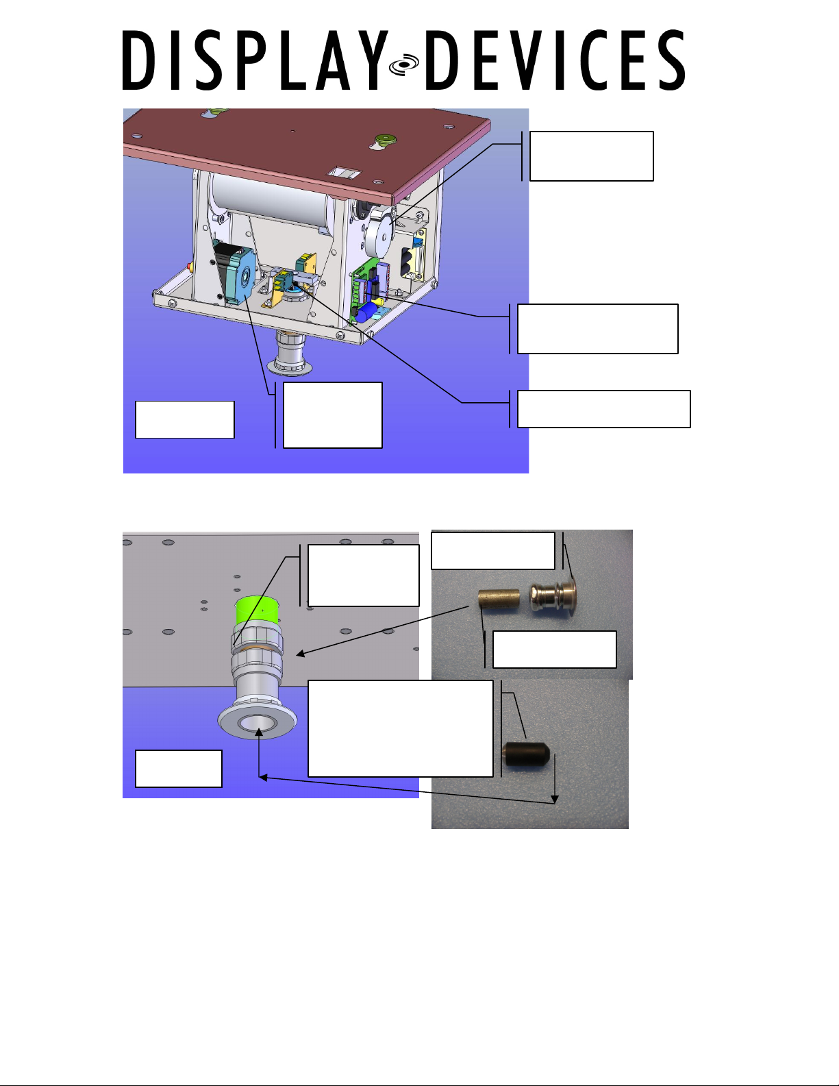
Brake
Mechanism
Microphone Lift
control board
Figure 2
Figure 3
Stepper
Motor
Upper piece
Fixed in lift
Limit switch activation
mechanism and
factory-installed
weight
Upper Limit switch
Ceiling Bezel
¾ “Conduit
2.)
3.)
4.)
Install the mounting plate using ½” hardware. Attach to structural channel
or a solid mounting surface. Be sure the plate is level front-to-back and
side-to-side.
Add a plumb bob to the mounting plate at the indicator hole and hang the
bob down to ceiling. This is the center point for the hole cutout location for
the microphone assembly.
Cut a 1.75” hole in the ceiling aligned with the plumb bob.
3
Page 4

5.)
6.)
7.)
8.)
9.)
Raise the lift to the mounting plate – insert the lugs into the key holes and
slide to narrow side of key hole slot.
Install the locking screw on the side of the unit.
There is a 2” long ¾ “ diameter conduit shipped with the unit, use a longer
piece if needed. Lower the microphone and weight down through the hole,
and thread through the conduit, conduit fitting, and ceiling bezel. Run this
assembly up through the hole and lock in place by tightening the upper nut
which if fixed to the bottom of the microphone lift.
Replace ceiling bezel.
If you’re installing this unit for purposes other than what the above
installation procedure describes, please call Display Devices Technical
Services at (303) 412-0399 for further assistance.
4
Page 5

Optional Speed Adjustment –
The MicLift’s lowering and raising speed can be changed from slow to fast.
The recommended speed is the factory default – slow.
Remove power to the unit.
Remove the side cover then remove the control board electronics cover. The jumper
is not connected and must be placed on both pins.
Slow speed – no jumper connected
Fast speed – jumper connected
Physical Installation
5
Page 6

Electrical, Signal and Control Installation
AC POWER
Audio Signal Remote Control
AC POWER 3 Pin XLR
6
Page 7

Remote Control - Pin out
1 UP
2 DOWN
3 STOP
4 COMMON
5 12V trigger in
6 +5V out
1.) Remove the j-box cover plate and connect AC power leads with wire nuts:
ground = green, neutral = white, hot = black.
2.) Connect the hardwired hand-held remote control to the 5-pin Phoenix
connector in the center j-box.
3.) Connect audio signal to the 3-pin XLR-f.
Three-button control – Contact Closure
‘Up’ button to pin 1
‘Down’ button pin 2
‘Stop’ button to pin 3
Common for all buttons to pin 4
Pin 5 & 6 are not used
Programming Show Position
Programming can only be done with the three-button control. If other methods of
triggering the lift are normally used, first program the lift with the remote and then
configure the lift for the other trigger method.
1.
Send lift to top position (‘Up’ button).
2.
Press and hold ‘Stop’ button for ten seconds.
3.
Press the ‘Down’ button. Lift will travel down. Press ‘Stop’ at the proper
show position. THIS MUST BE DONE IN ONE MOTION, DO NOT PRESS UP,
DOWN, OR STOP FOR FINE-TUNING OF POSITION.
4.
At proper position, press and hold the ‘Stop’ button for 10 seconds.
5.
Lift is now set. If you start the procedure and wish to quit after step 2, you
must reset power to the lift before normal operation will resume.
7
Page 8

Programming Ramping Distance
You may determine the location where the lift slows its acceleration. Programming can
only be done with the three-button control. If other methods of triggering the lift are
normally used, first program the lift with the remote and then configure the lift for the
other trigger method.
1 Send lift to top position (‘Up’ button).
2 Press and hold ‘Stop’ button for 10 seconds.
3 Press the ‘Down’ button. Lift will travel down. Press ‘Stop’ at the position where
you would like the microphone to begin slowing down. We recommend no less
than six inches below the finished ceiling. THIS MUST BE DONE IN ONE
MOTION. DO NOT PRESS UP, DOWN, OR STOP FOR FINE TUNING OF
POSITION.
4 At proper position, press and hold the ‘Stop’ and ‘UP’ buttons for 10 seconds.
5 Lift is now set. Press ‘Up’ to send the lift to the home position. Press ‘Down’ to
lower the lift, and ‘Up’ to send it to home position and verify where the ramping
point is. If you start the procedure and wish to quit after step 2, you must reset
power to the lift before normal operation will resume.
Refer to figure 2. The microphone lift is held in place by a solenoid brake
mechanism, so when the lift is told to move the brake will pull back and the
stepper motor will run to the lift to the desired programmed location.
Microphone Cable
The balanced microphone cable is connected to the 3-pin XLR. The color code of the
cable is braided/ground – pin 1, Blue/Blue with white stripe – pin 2, White/white with
blue stripe – pin 3. It is very important that the weight is on the cable. If the weight is
removed and you operate the lift, YOU WILL DESTROY THE MICROPHONE AND
LIFT! Also, make sure any splice is below the weight near the microphone.
8
Page 9

Optional Control Support
The next two control methods involve adding jumper wires on the Phoenix connector in
the center j-box. They are presented here for information only; please contact DDI for
further directions.
Low-Voltage Control signal and Single-Latching Contact
It is required that the lift is installed and the show position has been set. After setting
show position, jumpers must be added to the connector as shown below.
Low voltage (5 vdc < V < 24 vdc) control signal:
Voltage
Ground
Jumper from N4 Pin 1 to Pin 4, and N4 Pin 2 to Pin 4.
Trigger Voltage to pin 5.
Trigger Voltage ground to N4, pin 4.
(applied voltage sends lift up, no voltage sends lift down)
Single latching contact:
Jumper from N4 Pin 1 to Pin 4, and N4 pin 2 to pin 4.
Contacts between N4 Pin 5 and Pin 6.
(contact closed sends lift up, contact open sends lift down)
•
•
9
 Loading...