

Page 1
MFD-50
Microphone Rotating Lift
Installation Manual
READ ALL INSTRUCTIONS BEFORE BEGINNING INSTALLATION
Thanks for purchasing a Display Devices lift product. We’re sure your customer will enjoy this rotating lift
for years to come. Our products are designed to be maintenance-free saving you future service time. If
you experience any difficulties, please contact us at 303-412-0399. Thank you for your support.
tel: 303.412.0399 www.displaydevices.com
fax: 303.412.9346 tech@displaydevices.com
5880 Sheridan Blvd., Arvada, Colorado 80003
Page 2
RevA
MFD-50 Lift Series Installation
It is the responsibility of the dealer installer to ensure this product is properly supported and
meets all local building codes. DO ensure the table structure is capable of holding at least
four times
or state codes that apply to your specific area.
The MFD-50 is a furniture-mounted device which rotates (flips) to reveal a hidden microphone or other
small device from inside a table. It is designed for integration into boardroom / classroom tables. The
MFD-50 can be fitted with material from your table so it sits flush with the table top. Weight load
capacity is 3 lbs.
Tools required:
the combined weight of the MFD. This is a minimum requirement. Follow any local
Philips-head Screwdriver
Drill
Wire-management tools (crimper, etc.)
7/64” Allen wrench
Velcro or double-stick tape to attach microphone
Installation
Figure A
1.) Determine the orientation of rotation for the MFD-50 based on the size of the microphone being
used and the size/style of the table in which it will be installed.
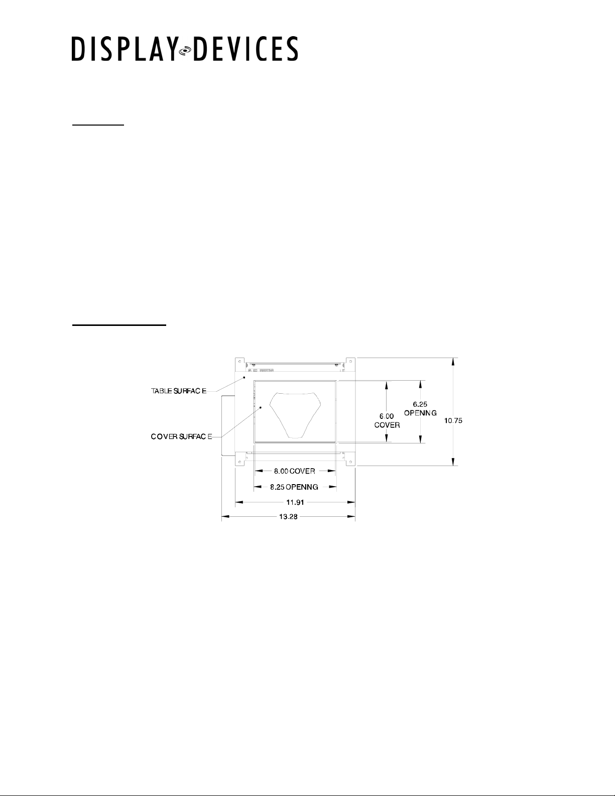
2.) Have a professional mill worker cut an 8.25” x 6.25” hole in the conference table based on the
orientation you’ve chosen. The bottom of the hole should be undercut with a route at a 45 degree
angle in the direction of rotation (as shown in Figure C). Be sure to allow enough clearance from
the edge of the table to fit the entire assembly and cabling. The MFD-50 is designed to mount to a
table top no more that ½” thick. If the table top is more than ½” thick, have the mill worker router
out a pocket that is at least 13.28” x 10.75” to house the unit.
3.) Before attaching the unit to the table, unscrew the four screws and remove the top plate from the
unit (as shown in Figure B, below). This is the surface to which the microphone/speaker will be
affixed.
6/7/2005
Page 3

RevA
MFD-50 Lift Series Installation
Figure B
4.) Determine the microphone location and signal pathway and drill a hole in the top plate large enough
to accommodate all the required cabling. Removing the connector on the microphone cable will
allow for a smaller hole.
Optional: For a more seamless appearance, have the mill worker attach a matching piece of wood
or veneer from the table to the top plate. Another wood surface may be attached in the same
manner to the plate in the “down” position as well. ½” is the maximum recommended cover
thickness. If you will be performing this modification, do not permanently attach the wood to the
plate until instructed to do so.
Figure C
5.) Run the necessary wiring from the microphone/speaker through the newly-drilled hole(s), through
the triangular pivot, and out the side of the unit.
6.) Use Velcro, double-stick tape, or a similar product to attach the microphone/speaker to the top plate
or wood surface. Depending on the equipment you are using, it might be easier to connect the
wiring before attaching the microphone or speaker. Then, reattach the top plate to the assembly.
If you are adding the wood cover, make sure there is enough clearance to allow the device to rotate
fully. Once you have verified this, attach the wood to the plate.
6/7/2005
Page 4

RevA
Alig
Alig
Alig
MFD-50 Lift Series Installation
7.) Before installing the MFD in your table, ensure that the top surface is level. If level adjustment is
required, loosen the (4) Phillips-head screws at each pivot end. Level side-to-side and front-toback. Tighten screws.
Figure D
nment Screws
Detent Lock Screw
nment Screw
nment Screw
8.) Detent adjustment is necessary only if the unit will not stay closed in the stowed position. Remove
the Detent Lock Screw with a 1/8” Allen wrench. Use a tweaker to turn the screw: counter
clockwise to loosen, clockwise to tighten. The end of the screw has a ball-bearing which settles into
a cup. It should be adjusted loosely so only the ball-bearing releases when the unit is pivoted.
Once adjusted, loosen 1/8 rotation (counterclockwise) and reinstall the Detent Lock Screw.
Detent Screw
(flat-head captive screw)
9.) If you have installed wood coverings on the MFD, it is recommended that you wire and test the
rotation before installing it in your table in case any additional modifications are necessary. See the
next section for information about powering the unit and using the included remote control. Make
sure that the wood surfaces are not impeding the rotation before continuing to the next step.
6/7/2005
Page 5

RevA
MFD-50 Lift Series Installation
10.) Line up the top plate of the MFD with the cutout in the table. Once it’s aligned properly, attach the
unit to the underside of the table by threading four wood screws through the holes in the side flaps.
Exercise caution when attaching the screws so they don’t protrude through the top of the table. It
is recommended that you work with your mill worker while performing this step to insure a seamless
installation. If unit is not level see step # 7 to re-level.
6/7/2005
 Loading...