

Page 1

PROJECTOR LIFTS
LCD-100, DL3B, DL3W
Installation &
Owners Manual
Vox: (303) 412-0399 On the Web:
Fax: (303) 412-9346 www.displaydevices.com
5880 N. Sheridan Blvd. tech@displaydevices.com
Arvada, CO 80003
Page 2

Contents
Important Installation Notes 3
Lift Placement 4
Lift Preparation 5
Ceiling Finish Methods 6
Enclosure Housing/Lifts Installation 7
Enclosure Housing – Side Panel Removal 8
Lift Installation 9
Enclosure Housing – Side Panel Replacement 10
Connecting Power 11
Projector Mounting 13
Cabling the Lift 14
Ceiling Closure 16
Adjustments 19
Specifications 19
Lift Removal 20
Maintenance and Safety 20
Emergency Operation 21
Remote Control Operation and Programming 22
Lift Communications Codes 25
Programming Chart 29
Troubleshooting Chart 30
Digital 9-pin Interface Schematics 31
Warranty 32
Feedback Form 33
1/17/07
2
Page 3

Important Installation Notes
Before starting…
DO Read all instructions before installation.
DO Leave wood blocks in place to protect you and the lift from damage until fully and
securely mounted.
DO Ensure the electrical outlet is readily accessible and complies with the lift and
projector specifications for voltages and amperages. (Show diagrams of 110v and 220v
receptacles.)
DO Check above the ceiling for obstructions, i.e., water pipes, wires, cables, duct work,
extreme temperature variations, etc. before beginning installation.
DO Ensure the ceiling structure is capable of holding at least four times the combined
weight of the lift and projector. This is a minimum requirement. Follow any local or
state codes that apply to your specific area.
DO Plan out your mounting hardware and tool requirements before installation.
DO Attach the projector, ceiling closure system, or other items to the lift only when the
lift has been properly installed and tested.
CAUTION:
Anytime that you are installing or performing maintenance on the lift,
disconnect power at the receptacle or breaker/fuse panel, program the lift to
MANUAL MODE, or activate the NO MOVEMENT switch on the side of the
control box to prevent inadvertent movement of the lift.
1/17/07
3
Page 4
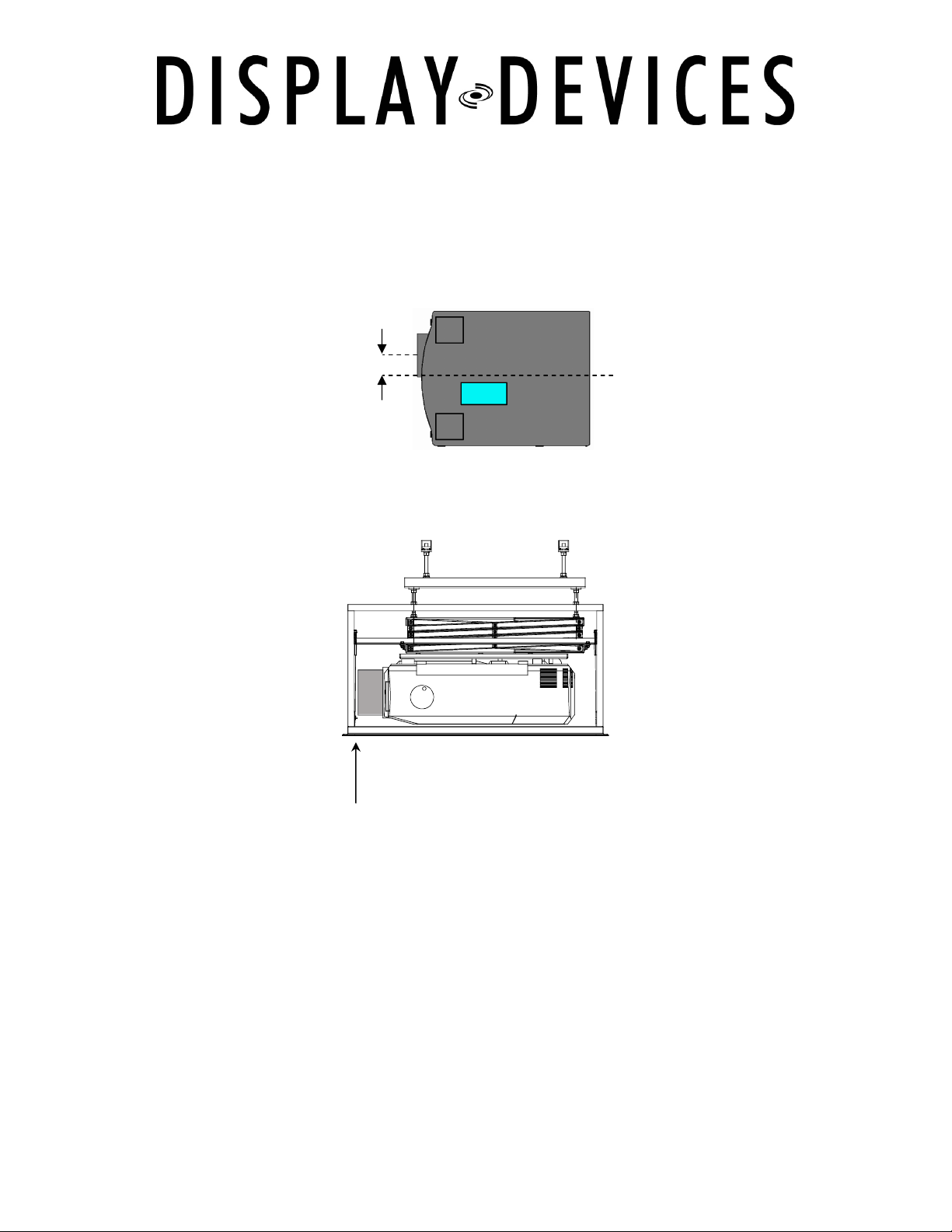
Lens Offset
Lift Placement and Location
Many projector lenses are not centered on the chassis of the projector. Ensure that the
centerline of the lens is aligned perpendicular to the center of the screen. Position the
lift offset the same distance as the offset of the projector lens. If your projector has
horizontal lens shift this is not as critical. We recommend offsetting the lift for optimum
projector alignment.
Projection Distance
If using a fixed focal length lens -- the screen-to-lens distance is critical. Offset the lift
position to compensate for the lens-to-lift difference. See your specific projector
manual for detail.
1/17/07
Fixed lens: measure distance lens-to-screen not
lift-to-screen
4
Page 5
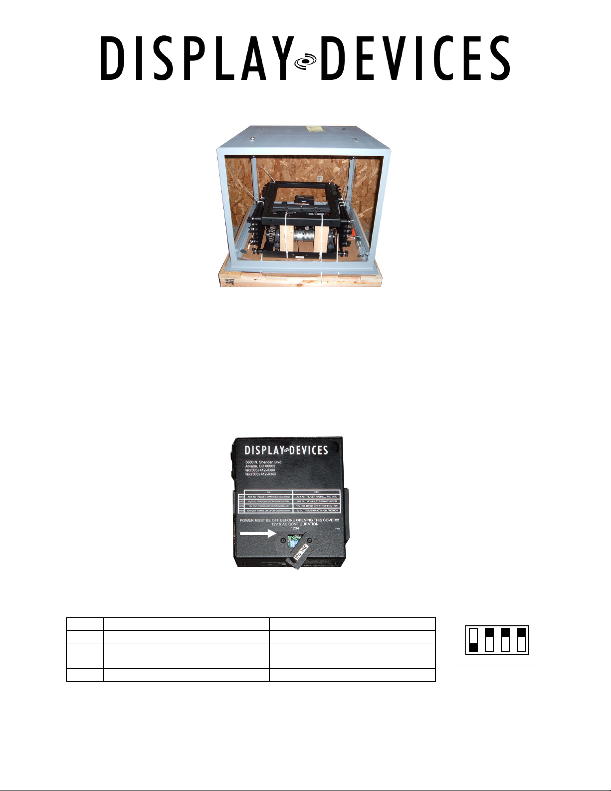
1 2 3 4
Default setting
Lift Preparation
Unpack Lift – remove phillips head screws & lag screws securing frame & lift to the
pallet. (photo of LCD-100 with Option 4). The lift is shipped upside down. Leave the
wood blocks and plastic tie wraps in place.
Control Box
NOTE:
SET DIP SWITCHES before you install the lift. Be sure there is no power connected to
the lift. The control box is located inside the lift on the upper frame. Depending upon
your lift model the location and orientation of the control box varies.
Dip switches are located under the small access panel on the Control Box attached to
the lift frame. Use a 1/16” Hex driver to open.
ON OFF
SW1 Aux AC Trigger (see SW2 below) Aux AC Trigger is on all the time
SW2 Aux AC Trigger upon going down Aux AC Trigger at show position
SW3 12V out turns off upon going up 12V out turns off at top position
SW4 12V out turns on upon going down 12V out turns on at show position
Dip Switch SW1: configuration only works in automatic mode.
Set the 12 volt trigger and AC Trigger based on your system design.
The factory default setting will not change for most installations.
ON
OFF
1/17/07
5
Page 6
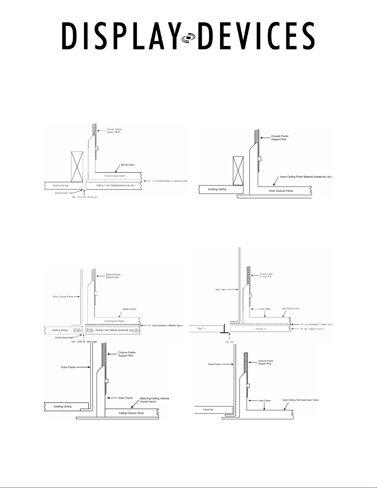
Typical Ceiling Finish Methods
Determine your ceiling closure system (OPT 1 – 4) and finish method as it can effect
the vertical placement of the lift.
Lift with Option 1 ceiling closure frame/panel
OPT1L
OPT1L 2X2
OPT3L or 4L
OPT3L or 4L 2X2
(Hard Ceiling)
OPT1
Option 3/4 Enclosure Frame
with Option 1 ceiling closure frame/panel
OPT3L or 4L
OPT3L or 4L 2X2
(T-grid Ceiling)
OPT3 or 4
OPT3 or 4 2X2
(Hard Ceiling)
OPT3 or 4
OPT3 or 4 2X2
(T-grid Ceiling)
1/17/07
6
Page 7
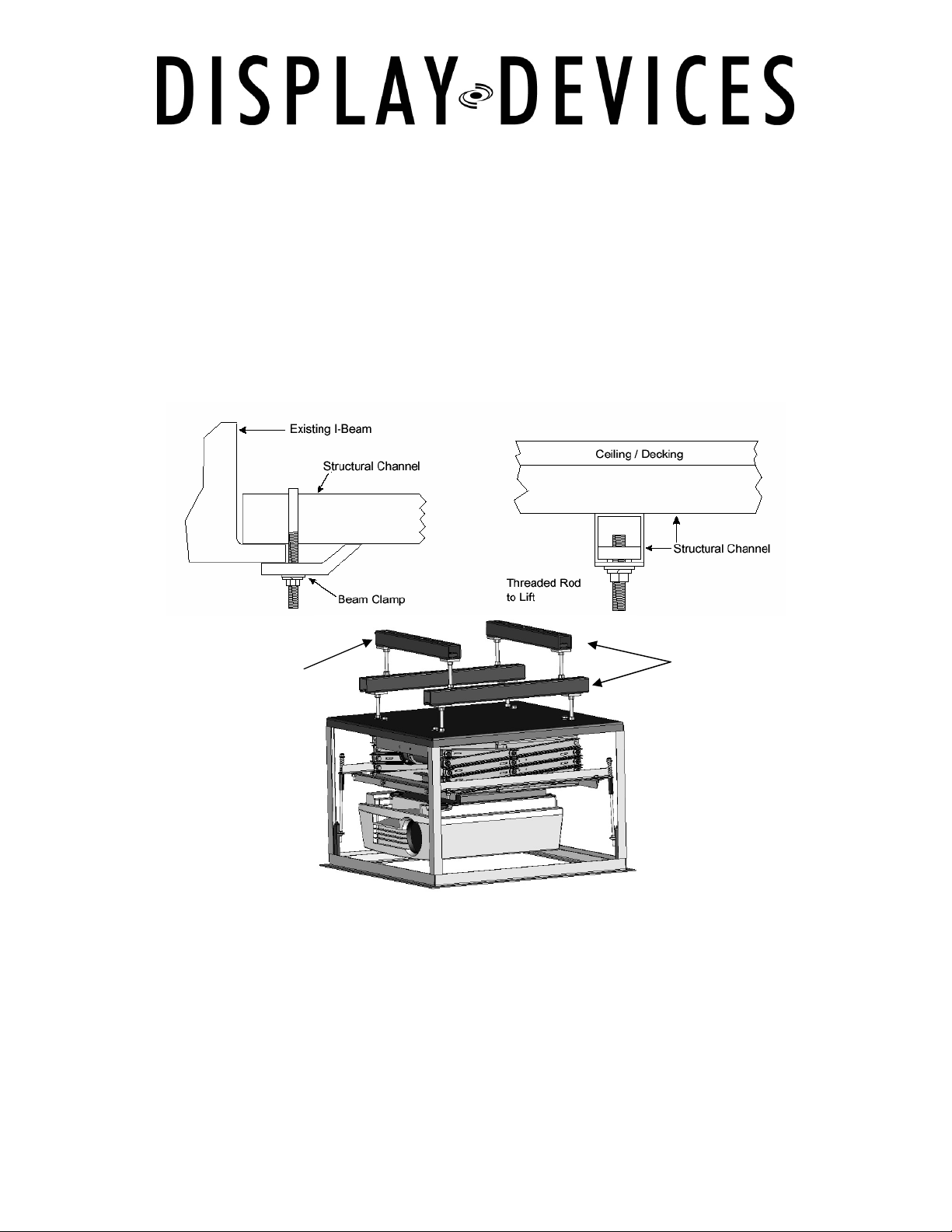
Attach to structural ceiling
Installation – Enclosure Housing and Lifts
Mounting hardware is not provided unless you ordered the option UMK (Universal
Mounting Kit). Be sure to have all your mounting hardware and tools readily accessible
before installation. Consult your local building codes for proper structural attachment.
Tools you will need:
Safety glasses, Socket set, Box wrenches, Adjustable wrench, Magnetic torpedo level
(two, if possible), Ladders or manlift, Genie Lift or heavy straps and pulleys (for DataLift
and DataLite Models), Knockout kit or Hole saw, ½” Drill and/or ½” Hammer drill.
If space permits: use
structural channel left-toright and front-to-back for
better positioning of the lift.
We recommend you install mounting hardware into a structural channel. All hardware
should be at least ½” (M12) in diameter for the DataLift (DL3B) and DataWide
(DL3W) series, or 3/8 ” (M10) for the DataLite (LCD100) series.
You should use angled stabilizers if threaded rods extend 2’ (60 cm) or more between
structural channel and the lift. You should also leave the threaded rods slightly loose to
ease in alignment and leveling after installing the lift. You need to make sure all
hardware is securely tightened at the end of your installation.
1/17/07
7
Page 8

Optional Enclosure Housing –Side Panel Removal
If you are not installing the OPT3 (Plenum Housing Enclosure) or OPT4 (Non-Plenum
Housing Enclosure) proceed to Part 4.
The OPT4 is the enclosure frame without side panels. You may skip the steps on the
OPT3 panels if you are installing the OPT4 only.
Use a Sharpie pen to mark the alignment of the side panels to the frame so you can
reinstall them from the side they were removed from. Take note the location of the
electrical outlet and the signal cables in relation to the lift location. Mark where you
want knock-outs for cable pass-through on the side panels -usually in the opposite
upper corners. (½” knockout for control/video cables & 1¼” knockout for AC power)
Keep these cables away from each other to avoid electromagnetic interference.
Remove the screws holding side panels from the frame, then lift out the plenum panels.
Be careful, the edges and corners are SHARP!
The lift is shipped upside-down with the specific projector’s mounting adapter bolted to
the bottom of the frame.
The outer frame will have a white sticker indicating the FRONT and TOP side of the
frame.
Note:
DataLite and DataLift models attach to the pre-installed bolts on the top of the
enclosure frame. DataWide models attach to pre-drilled horizontal holes on the front
and rear channels.
For DataLift (DL3B) and DataLite (LCD100) be sure the lift hanging hardware is installed
in the frame before mounting the enclosure to the structural ceiling.
Optional Enclosure – Mounting
Remove the mounting adapter from the bottom frame of the lift (7/16” socket/wrench).
Raise the Option 3 or 4 housing to the mounting points – add washer and nuts, then
tighten. Make sure the threaded rod you are attaching to does not protrude further
than ¼” past the nut. If there is too much threaded rod in the housing, the lift may
not be high enough in the housing – then your closure panel may contact the projector
prior to closing fully. After you have the mounting structure and/or housing installed in
the ceiling, you are ready to raise the lift into position and mount it.
1/17/07
8
Page 9
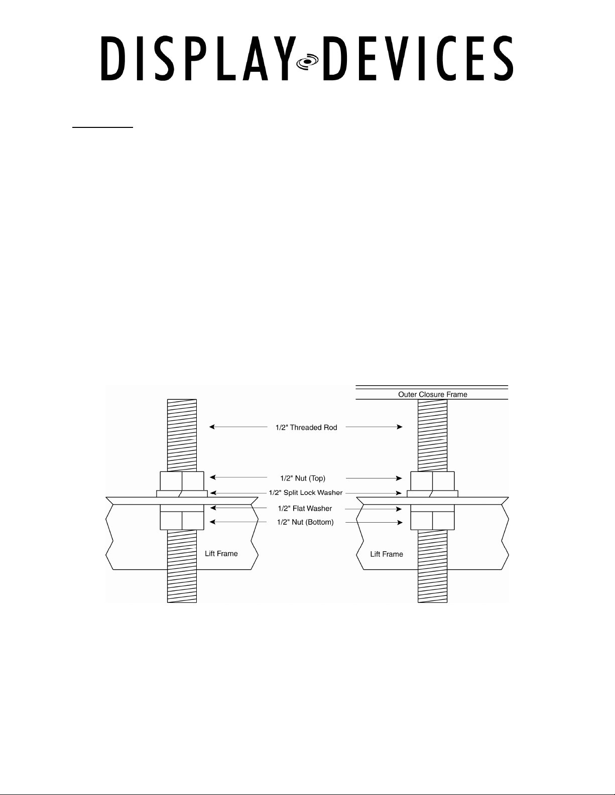
Hardware Order
Lift Installation
CAUTION!
The lift is heavy. Take proper safety precautions and get adequate help when
raising the lift. We recommend using a Genie™ or scissor-type lift when
installing the heavier DataLift and DataWide models. Add a safety line to the
lift to prevent it from falling to the floor in the event of an accident.
Remove the mounting adapter from the bottom frame of the lift (7/16” socket/wrench).
Before you begin, be sure the threaded rods have a nut and split washer above the lift
frame, and a flat washer and nut below the frame. These can be temporarily held in
place with tape, glue or gum.
Use 3/8” hardware for the DataLite models, and 1/2” hardware for the larger, heavier
DataLift and DataWide models.
Raise the lift into position and add hardware. Follow the hardware order to ensure
stability and accuracy when leveling the lift after you have successfully mounted it.
1/17/07
9
Page 10

Note:
The following are some of the most important steps in proper lift installation!
Use a torpedo or bubble level to level the top frame of the lift. You may want to use
more than one.
1. Level the lift from the right front to the left front.
2. Level the lift from left front to left rear.
3. Level the lift from right front to right rear.
4. Level the lift from right rear to left rear.
5. Recheck.
6. Recheck again.
7. To be absolutely positive, recheck again.
8. Tighten all hardware.
You may cut the tie wraps and remove the wood shipping blocks. Be sure to remove all
blocks and all tie wraps on both sides of the lift.
Optional Enclosure - Side Panel Replacement
If this is a plenum-rated housing, (OPT3), you can now replace the side panels that
are not knocked out. Be sure the correct panel goes on the correct side of the frame.
Next, install the strain relief/cable clamps in the panels that are knocked out, with the
screws on the inside, facing down.
It may be convenient to put the cables through at this time, depending upon the
ceiling’s finish and accessibility. If it is drop-tile ceiling, accessibility should not a
problem.
If the ceiling is a finished sheetrock or other solid material, you may need to feed the
cables through the connectors first, before you reinstall the panels.
1/17/07
10
Page 11

Connecting Power
Verify voltage at the outlet/power source for the projector/lift. You can now connect the
lift’s power cord to a properly rated electrical circuit in the ceiling near the lift.
Next, plug the remote control unit cable into either of the two 9-pin control remote
ports on the side of the control box.
Tighten the cable clamps / strain relief connectors as required.
If using the 12V trigger and/or AC Trigger, plug 1/8” mono mini plug on the sides of the
control box at this time. Be sure the cable won’t interfere with the lift mechanics.
Do not use a stereo mini connector.
(Tip / Ring / Sleeve)
Use the provided 1/8” mono mini connector.
(Tip / Sleeve)
Be sure the cables do not sag into the lift mechanism during its operation.
Remove the tie wraps and remove the wood shipping blocks. Be sure to remove all
blocks and all tie wraps on both sides of the lift.
Caution!
If you do not remove the wood blocks, and attempt to lower the lift, they will
fall out when the unit is lowered. If you forget to remove the tie wraps from
the wood blocks and scissor mechanisms, lift damage will occur.
After following these precautions, you are now ready to turn on the power switch on
the lift control box.
On the side of the control box, you will find the small black switch labeled NO
MOVEMENT. The lift is shipped from the factory with the NO MOVEMENT switch in the
ON position.
Flip the NO MOVEMENT switch to the OFF position. The LED will then blink twice. If the
NO MOVEMENT switch is on, the STATUS LED on the control box and the remote
control will be on solid -non blinking.
1/17/07
11
Page 12

12VDC Out
No Movement Switch
12VDC In
Main Power Switch
AC Input
AC Trigger
Caution!
Make sure all tools, cables and body parts are clear of the lift before pushing
the UP button.
With the hand-held remote control, press the UP button to send the lift to the home
position. Refer to the separate manual for the remote control (enclosed) for details on
operation of the remote and program the lift’s functions.
For this installation, here is a guide to the LEDs on the control box and the remote, and
what the blinking means:
If the LED… It means… Fix it by…
Is Continuously Blinking The NO MOVEMENT switch on
the side of the control box is
activated. This disables all
movement of the lift.
Blinks twice (after unit is
powered up, LED then stops
blinking
Blinks three times Dual motor current problems* Call DDI technical support
Blinks four times Motor is not moving Check the power to the motor
Blinks five times ** Low AC line voltage Check circuit voltage
Blinks six times Cables off the drum Re-cable the drum(s)
Blinks seven times Lower limit safety switch
*
2004 or earlier – non-volatile memory corrupted
**
stops automatically after voltage is restored to proper level
The lift is operational
activated
Moving the switch to the OFF
position
or for a mechanical
obstruction on the lift
Follow steps on page 7 of the
remote instructions
Circuit
Breaker
Remote
Control
Input Ports
1/17/07
AC Configuration
DIP Switches
Refer to the Remote Control Operators Manual for clarification as needed.
12
Page 13

Front
Back
UP
DOWN
STOP
OVERRID
E
Projector Mounting
Most lifts are shipped with the projector mounting adapter attached. Remove it from
the lower frame of the lift, if you have not already done so.
Find the projector’s center of gravity using a dowel, pipe or broom handle.
Invert your projector and attach the mounting adapter to the bottom of the projector
with the enclosed hardware.
Use the Remote Control to lower the lift to a good working height – see the Remote
Control Operation section for further information.
Place the lift in manual mode - use a small point (straightened paperclip) press and hold
the OVERRIDE button then press the UP button. Release UP then release
OVERRIDE.
Test the unit by pressing the DOWN button. It should move only when the button is
depressed. The lift will stop when the button is released.
Attach the adapter to the lift with the projector’s center of gravity under the wire rope
and eye bolts of the lift. If you ordered OPT11- Pre-wire package proceed to Part 7.
SET
These two bottoms are accessed with a small point
1/17/07
13
Page 14

Cabling the Lift
Caution:
Using large-diameter RGB and other signal and/or control cable is not
recommended on Display Devices’ lifts.
This type of cable has too large of a bend radius to allow it to fit in the cable
management clips mounted on the outside of the scissor assembly.
If your system uses large cables, keep them coiled neatly to the top of the lift, and
provide an interconnected miniature RGB cable to make the run down through the cable
management clips to the projector.
Attaching the Cables
Using the hand-held remote, bring the lift down to the MAINTENANCE position. See the
separate Remote Manual to learn how to program this position. The signal, power and
control cables can now be routed into the cable management clips on sides of the
scissor assembly.
When routing the cables always start at the fixed end of the scissor on the bottom
frame. Your cable routing will end at the fixed end of the scissor on the top frame.
1/17/07
14
Page 15

The lift is shipped with a sample cable in the clips – after reviewing the sample cable remove. Attach your cables in a likewise manner. Small cable tie wraps are supplied for
securing the cables into the clips.
Use both of the small holes when attaching the cables to the clips. Leave a loop at the
end of each scissor.
Carefully route the projector cables starting at the bottom scissor towards the front of
the lift and work towards the top front of the lift. Be careful you do not allow the
cables to twist.
NOTE:
It is common practice to keep the signal cables (audio, video, RGB) separate from the
projector power and control cables to prevent signal interference. Utilize the clips on
both sides of the lift for isolation.
Raise the lift to its home position with the UP button (in MANUAL mode) slowly,
carefully, and intermittently. Observe carefully the cables rigged to the sides of the lift
and watch for any problems.
Bring the lift down with the DOWN button. Again, watch for any problems and ensure
proper overall operation. Do this several times.
If you did not set the 12-volt trigger and AC configuration, revisit Part 1 and set the Dip
Switches for your system design.
You are now ready to attach the ceiling panel closure system.
1/17/07
15
Page 16

Slider (X2)
Slider (X2)
CTB Mount (X2)
CTB Mount (X2)
Assembly (X4)
Assembly (X4)
Ceiling Closure System – CTB Mounts & Sliders
Threaded Rod
Option 1 Lipless
Ceiling Closure Frame
Threaded Rod
Option 1 Lipped
Ceiling Closure Frame
NOTE: If you are not installing an OPT1 Ceiling Closure Frame, proceed to Part 8.
Lower the lift to a workable height. Install the CTB mounts to the corresponding holes
in the front and rear on the lower frame of the lift. (If your system includes the EMRCM
Rotating Option, attach the CTB to the EMRCM lower frame). See the supplemental
EMRCM/LIFT Interface directions.
Use ¼-20 x 1” bolts, ¼” split lock washers, and ¼” flat washers to attach the CTB
mounts to the lower lift frame.
Place the sliders on top of the CTB mount tabs that extend out from the right and left
sides. Add hardware but do not tighten the sliders to the tabs completely as they will
need to be adjusted for alignment.
1/17/07
16
Page 17

CTB Mount (X2)
NOTE:
If you have the 2X2 configuration, you will not use the sliders (front-to-back bars).
Option 1 2X2 Lipless
Ceiling Closure Frame
For a Lipless Closure System (OPT1L, OPT3L) cut a plywood backer board and ceiling
media (drywall, ceiling tile) 3/8” smaller than the hole cut out in the ceiling.
Glue or screw the ceiling media to the backer board. Add two 1” x 4” wood supports
across the width of the closure frame. Screw through the wood supports into the
plywood backer board.
NOTE:
Leave enough play in the screws to slide the ceiling closure for precise alignment of the
panel. Prep the ceiling closure panel by painting it to match the existing ceiling.
If you have a Lipped Closure System (OPT1, OPT3), fit your ceiling tile or other ceiling
media within the closure frame.
1/17/07
17
Page 18

Ceiling Closure System – Threaded Rod Attachment
Thread the (4) ¼-20 rods into the ceiling closure frame, stopping about 1½” from the
bottom.
Lift the closure panel and insert the rods into the slider.
Add the nylon shoulder bushing, spring, ¼” flat washer, and ¼-20 lock washer on the
top end of the rod.
Carefully raise the lift using the remote control.
Be sure the inner closure frame is centered inside the OPT3 or OPT4 outer frame. After
the closure panel is centered, tighten the bolts that attach the sliders to the CTB
mounts.
Finally, adjust the rods so that the ceiling closure panel fits flush with the ceiling.
When adjusting the Lipped Closure System (OPT1, OPT3), the springs should compress
about 1/8” to 1/4”.
1/17/07
18
Page 19

Final Adjustments
Operate the lift up and down several times to verify all adjustments and ensure proper
overall operation.
Place the lift in Manual Mode – press and hold Override, press and release UP, relase
Override. Raise the lift to its home position with the UP button slowly, carefully, and
intermittently. Observe carefully the cables rigged to the sides of the lift to watch for
any problems.
Bring the lift down with the DOWN button. Again, watch for any problem and ensure
proper overall operation. Adjust the closure system as needed.
Operate the lift up and down several times.
Place the lift in automatic mode. (press and hold OVERRIDE, press and release STOP.
If you did not set the 12-volt trigger and AC configuration, revisit Part 1 and set the Dip
Switches for your system design.
The lift is now installed and ready for operation.
Specifications
DataLite LCD-100 DataLift DL3B DataWide DL3W
Operating
Temperature Range
Horsepower 1/12 – 110V or 220V 1/12 – 110V or 220V 1/12 x 2 – 110V or 220V
Current Draw .6A @ 110V
32° – 104°F
0° – 40°C
.3A @ 220V
32° – 104°F
0° – 40°C
1.2A @ 110V
.6A @ 220V
32° – 104°F
0° – 40°C
2.4A @ 110V
1.2A @ 220V
1/17/07
19
Page 20

Lift Removal
Disconnect all cables from the projector. It may be necessary to remove all cabling from
the cable management clips on the side of the lift if disconnects were not installed.
Remove the Ceiling Closure Panel.
Remove the projector from the lift.
Place wood blocks between the upper and lower frame of the lift, and secure them with
tie wraps. The wood should be ½” to 1” longer than the fully-retracted lift height to
prevent the limit switches from being crushed. Close the lift up until contact is made
with the blocks.
Disconnect the AC power and remote control cables.
Support the lift with an appropriate support system (Genie Lift, winch, rope / pulley).
After the lift is secured, remove the mounting hardware. Caution: mounting hardware
may fall when removed.
Lower the lift from the ceiling, and crate for transport.
Maintenance & Safety
All Display Devices lifts are virtually maintenance-free.
Annual safety checks are suggested to insure continued reliability and safe operation.
Inspect lifting cables for wear.
Inspect drive belt/chain for any wear.
If equipped with safety strap(s), verify that they are drawing smoothly in and out of the
clutch area, and that there is no sign of wear and tear. Also check them for proper
locking operation with a quick tug on the strap(s).
Check motor and bearings for any leakage.
Verify limit switch operation.
1/17/07
20
Page 21

Emergency Operation
If your lift has traveled below the service position, and activated the lower limit safety
switch, you will need to refer to the Remote Manual, and/or follow the steps below.
1) Open the back cover of the handheld remote control case, or remove the switch
plate from the wall box.
(More detailed information is in the Remote Control Manual page 26.)
2) Press and hold the STOP button for 15 seconds to clear the error. Press the
EMERGENCY button in the circuit board, press the UP button and release, then
release the EMERGENCY button. The Lift should travel upward.
3) Verify operation and reprogram positions if necessary. See the Remote Control
Manual enclosed as a supplement.
If the above steps do not resolve the problem, call Technical Support at 303.412.0399
during normal business hours, or E-mail Display Devices, Inc. at
tech@displaydevices.com.
1/17/07
21
Page 22

Front
Back
UP
DOWN
STOP
OVERRIDE
Remote Control Unit
The Display Devices hand-held Remote Control Unit is a versatile, multi-functional
programmable unit for lift operation.
The UP button moves the lift to the home position in AUTOMATIC mode, and raises the
unit intermittently on command (in MANUAL mode).
The DOWN button lowers the lift to its SHOW position in AUTOMATIC mode, and
lowers the unit intermittently on command in MANUAL mode.
The STOP button stops the lift’s motion while in AUTOMATIC mode.
The OVERRIDE held down then followed by the DOWN button will lower the lift to
service position while in Automatic Mode.
The SET and OVERRIDE buttons on the back of the unit are used in combination with
the three command buttons on the front to program lift functions.
The EMERGENCY OVERRIDE button should only be accessed in case the lower limit
switch is activated. This will be discussed later.
* It is recommended to keep the handheld 9-pin remote attached to the control box in
addition to any control system (Crestron/AMX/etc.) for easy maintenance override or
control system failure.
EMERGENCY – accessible only
with back cover removed
SET
These two bottoms are accessed with a small point
1/17/07
22
Page 23

Front
Back
UP
DOWN
STOP
OVERRIDE
Front
Back
UP
DOWN
STOP
OVERRIDE
Program the lift to MANUAL MODE –
To set Show and Service positions the lift must be in Manual Mode.
1. Use a small point (straightened paperclip) press and hold the OVERRIDE button
then press the UP button. Release UP then release OVERRIDE.
2. Test the unit by pressing the DOWN button. It should move only when the button
is depressed. The lift will stop when the button is released.
SET
These two bottoms are accessed with a small point
Set the SHOW position
This is the intermediate level for “on screen” projection. Be sure to start this procedure
from the HOME position.
1. Program the remote to MANUAL MODE (OVERRIDE + UP). Press and hold the
OVERRIDE button, then press the UP button. Release UP, then release
OVERRIDE.
2. Lower the lift with the DOWN button to its desired projection position.
3. To program the remote to the SHOW position, press and hold the SET button then
press the UP button. Release UP, then release SET.
4. To return the remote to the AUTOMATIC MODE, press and hold the OVERRIDE
button, followed by the STOP button. Release STOP, then OVERRIDE.
5. Return the lift to the HOME position by pressing the UP button once.
6. Test the operation of the lift to verify it has accepted your program.
7. Press the DOWN button once. The lift will travel to its programmed position. If the
lift does not travel to the position just programmed, repeat this process.
* Remember, the remote must be in AUTOMATIC MODE for the commands to operate
correctly.
SET
These two bottoms are accessed with a small point
1/17/07
23
Page 24

Front
Back
UP
DOWN
STOP
OVERRIDE
Set the SERVICE / MAINTENANCE position
This is lower than the SHOW setting, bringing the lift to a level making maintenance,
service, lamp and filter changes, and projector adjustments easier. Be sure to start this
procedure from the HOME position.
1. Program the remote to MANUAL MODE – (OVERRIDE + UP). Press and hold
the OVERRIDE button, then press the UP button. Release UP, and then
release OVERRIDE.
2. Lower the lift with the DOWN button to its desired position for the easiest
access for maintenance and repair.
3. To program the remote to the SERVICE/MAINTENANCE position, press and hold
the SET button, followed by the STOP button. Release the STOP, and then
SET buttons.
4. To return the remote to the AUTOMATIC MODE, press and hold the OVERRIDE
button, followed by the STOP button. Release the STOP, and then OVERRIDE
buttons.
5. Return the lift to the HOME position by pressing the UP button once.
6. Test the operation of the lift to verify it has accepted your program. Press and
hold the OVERRIDE button, followed by the DOWN button. The lift will travel
to its programmed position.
Remember, the remote must be in AUTOMATIC MODE for the programmed positions
operate correctly.
SET
These two bottoms are accessed with a small point
Return to AUTOMATIC MODE
1. Press and hold the OVERRIDE button, followed by the STOP button. Release the
STOP then OVERRIDE buttons.
In the AUTOMATIC MODE, the lift will automatically descend to the proper show level,
rise to the HOME position, and descend to its lower limit service and maintenance.
1/17/07
24
Page 25

Access Service/Maintenance Position
Press and hold OVERRIDE then press DOWN – release. The lift will lower to service
position while in Automatic Mode.
LED Communications Codes
BLINKING LEDs ON THE REMOTE OR CONTROL BOX
If the LED is… It means… Fix it by…
Continuously Blinking The NO MOVEMENT switch
on the side of the control
box is activated. This
disables all movement of
the lift.
Blinks twice (after unit is
powered up, LED then
stops blinking
Blinks three times Dual-motor current problem Call DDI Tech Service.
Blinks four times Motor is not moving Check the power to the
Blinks five times Low AC line voltage Check circuit voltage
Blinks six times Cables off the drum Re-cable the drum(s)
Blinks seven times Lower limit safety switch
The lift is operational
activated
Clearing Errors: Press and hold the STOP button for 15 seconds and release. If the
same error occurs, call Display Devices technical support.
Moving the switch to the
OFF position.
motor or for a mechanical
obstruction on the lift
First cycle the power off
then on and take note of
what the LED does upon
power up. Follow steps on
the next page.
1/17/07
25
Page 26

Lower limit switch
Recover Lift from LOWER LIMIT SWITCH ACTIVATION and EMERGENCY
OVERRIDE
When the Lift is lowered beyond its lower limit or Service/Maintenance position, a small
wheel bearing activates a safety shut-off on the lower limit switch. It is located on the
channel near the wheel bearing on the scissors. If the lift will not respond to any
command buttons and the LED on the remote and Control box blinks seven times,
proceed with the following.
The procedure is also required
if a new control box is installed.
1. Remove the back cover of the remote control with a small Phillips-head
screwdriver. Now you have access to the EMERGENCY OVERRIDE button on
the circuit board.
2. If the LED is blinking you must clear the error. Press and hold the STOP button
for 15 seconds then release.
3. Hold in the EMERGENCY OVERRIDE button, followed by the UP button. The
lift will return to its HOME position in the ceiling, allowing the lift to reset its
memory.
4. Put the cover back on the remote.
5. Put the lift into MANUAL MODE (OVERRIDE + UP).
6. Press the OVERRIDE and SET buttons at the same time. This allows you to set
a new Electronic Lower Limit position for the lift.
7. Press and hold the DOWN button until the small wheel bearing on the upper
frame is ½ inch from tripping the lower safety switch (release button before
wheel bearing touches switch) or reaches the desired SERVICE/MAINTENANCE
position (but not so low as to activate the safety switch again!)
8. Press both the OVERRIDE and SET buttons at the same time. This will reset
the electronic lower limit switch.
9. Return the remote to AUTOMATIC MODE (OVERRIDE + STOP).
10. Press the UP button, and allow the lift to travel up to its home position.
11. Operate the lift to verify the Show and Maintenance positions are programmed.
1/17/07
26
Page 27

1/17/07
27
Page 28

Summary of the Remote Control Functions
The OVERRIDE and SET buttons are hidden on the back of the remote control. The
lower button is OVERRIDE and the top button is SET. A straightened paper clip or
similar device will be needed to activate them.
When using the OVERRIDE and SET buttons, these buttons must be pressed first and
released last in the sequence.
To set the show position, press and hold SET, press UP, release UP, and then release
SET.
Automatic Mode:
UP moves lift to the top position, DOWN moves lift to show position, and STOP stops
the motion of the lift.
UP, DOWN, and STOP are functional while the lift is moving.
Manual Mode:
UP and DOWN buttons move the lift only while the buttons are depressed. Unit will stop
at the top limit switch.
STOP stops the motion of the lift at the current position.
OVERRIDE & DOWN from the show position moves the lift to the maintenance position.
OVERRIDE & UP from any position will place the lift into manual mode.
OVERRIDE & STOP terminates the manual mode and returns the lift to automatic mode.
SET & UP sets show position and only works in manual mode.
SET & STOP set the maintenance position and only works in manual mode.
When in the automatic mode, press and hold OVERRIDE, then press STOP & UP
together to place the unit into test mode. This will continually cycle the lift between
home and show positions, pausing at each position. To terminate, press stop.
The NO MOVEMENT switch is located on the control box mounted to the lift frame and
disables all movement of the unit. Remote control buttons become inactive.
EMERGENCY OVERRIDE & UP raises the lift only after the lower safety switch has been
triggered.
Holding the STOP button for 10 seconds will clear the last Communication Code
(blinking LED).
1/17/07
28
Page 29

Programming Maintenance and Show Positions
Put the lift into MANUAL
MODE – Press
OVERRIDE & UP
Press DOWN to lower
lift to desired
Maintenance position
(lift will stop when button
is released)
Set Maintenance
Position
Press SET & UP
Return to AUTO mode
Press OVERRIDE &
STOP. Press UP
button, lift should travel
to home position
To test:
Press OVERRIDE &
DOWN buttons, lift
should travel to position
just set and then stop
Press DOWN to lower
lift to desired Show
position (lift will stop
when button is released)
Set Show Position
Press SET & UP
Return to AUTO mode
Press OVERRIDE &
STOP. Press UP
button, lift should travel
to home position
To test:
Press DOWN button, lift
should travel to position
just set and then stop
If yes, press UP
and lift is ready for
operation
1/17/07
If No, press UP
and start again
If No, press UP
and start again
If yes, press UP
and lift is ready for
operation
29
Page 30

10 second delay
to beginning
beginning
beginning
beginnin
g
beginning
box
sound
problems?
Call DDI
travel upward?
YES: Does the lift
proceed to beginning
release adjustments –
NO: Call DDI for brake
proceed to
control box –
NO: Plug motor into
YES: Is the motor
unit is ready to use
2 BLINKS: Normal –
connector plugged
Indicated by click
YES: Is the brake
releasing properly?
into control box?
have any
mechanical
NO: Does the lift
frame engaged?
NO: Are the safety
switches on the top
control box
replacement
NO: Call DDI for
call DDI
mechanical problems,
YES: If the lift has any
proceed to
jumper past the
YES: Release or
switch, rest power,
box
YES: Plug in the
slot. Call DDI for
replacement parts
NO: Call DDI for
replacement control
box
NO: Call DDI for
replacement control
then call DDI for
YES: Verify wiring
replacement control
beginning
– proceed to
YES: Reset breakers
YES:
Are the circuit
breakers tripped?
NO: Correct wiring
to match schematic
NO: Is the remote
control connected?
NO:
proceed to
Hook up power –
Troubleshooting Chart
1/17/07
– proceed
SOLID LED: no
blinks – Turn No
Movement Switch off
parts
for replacement
motor failure. Call
3 BLINKS: ** dual
YES:
Blinks?
Number of LED
** 2004 or earlier is non-
volatile memory corrupted
sound?
NO: Does the lift
make a click of hum
4 BLINKS:
Does the lift move?
YES:
unplugged?
Is the slot sensor
wheel damaged or
IS THE LED
ACTIVE UPONM
POWER UP? after
YES: Turn lift off,
restore power, turn
lift of and proceed to
line voltage
voltage. Verify low
5 BLINKS: Low AC
call DDI for
6 BLINKS: Safety
switch triggered –
see manual for
override process
7 BLINKS: Safety
switch is triggered –
instructions
NO: Is the unit
receiving power?
Verify w/ voltmeter
30
Page 31

1/17/07
31
Page 32

Warranty
This product is warranted against defects in material and labor for 12 months from the date of shipment
from Display Devices, Inc. Unit must not exhibit previous alterations or repairs except those performed
by an authorized Display Devices dealer, distributor or factory service center.
Exclusions:
Lack of routine maintenance, normal wear and tear, misuse, improper operation or installation, neglect,
abuse or acts of nature.
Fax or mail to:
Display Devices, Inc.
5880 N. Sheridan Blvd.
Arvada, CO 80003
(v) 303-412-0399
(f) 303-412-9346
Company Information:
Name:
Address:
City/State/Zip:
Phone:
Fax:
Dealer purchased through:
Date purchased:
Model #:
Serial #:
Comments:
1/17/07
32
Page 33

Help us help you!
We value your feedback about our products. Any input you can provide will help us
design and build better products for you. Please take a few minutes to answer the
following questions. Use a 1 to 10 scale with 1 being poor to 10 being excellent.
When complete, fax it back to us at 303-412-9346. Thanks for your support!
Product Quality
Appearance of finish
Packaging
Dimensionally correct
Mounting Bracket alignment (if applicable)
Installation
Ease of installation
Understandability of Manual
Customer Service
How was your purchasing experience?
Was the product shipped on time?
Was your order shipped complete?
Product Improvement
Are there any features or options you would like to have available?
If we designed and built a new product for you, what would it be?
What can we do better for you next time?
Order Number
Name Company
Phone Fax
E-mail
1/17/07
33
 Loading...