

Displax SKINFIT User Manual

TECHNOLOGY FOR THE MULTITOUCH GENERATION
MKT.331.1 | DISPLAX SKIN FIT | DISPLAXTM MULTITOUCH TECHNOLOGIES 1
SKIN FIT
USER GUIDE
LARGE MULTITOUCH PROJECTED CAPACITIVE
TECHNOLOGY FOR THE MULTITOUCH GENERATION
MKT.331.1 | DISPLAX SKIN FIT | DISPLAXTM MULTITOUCH TECHNOLOGIES 2
DOCUMENT REVISION HISTORY AND APPROVAL
Release date
Code
Prepared by
Approved by
2017/12/12
MKT.331.1
António Rocha
Nuno Fernandes
Pedro Marques
Pedro Talaia
Tom Kermeen
CONTACT
Displax S.A.
Parque Industrial de Adaúfe
Rua Soldado Manuel Magalhães, 68
4710-167 Braga, Portugal
URL: http://displax.com/
Tel.: +351 253 265 506
e-mail: touch@displax.com
GPS: N 41° 36' 06'' (41.60167); W 08° 24' 38'' (8.41056)
PRODUCT COMPLIANCE
DISPLAX is a certified company under the ISO 9001
standard which establishes the requirements for a
quality management system, meaning that our
R&D, production, support, sales and marketing
processes are organized around quality
management practices to guarantee the
effectiveness of our work and the satisfaction of our
clients.
Our products are compliant with RoHS - Restriction of
Hazardous Substances, meaning that they do not
contain substances which might put at peril the
product users, they are also compliant with the
Electromagnetic Compatibility Directive 2014/30/EU,
meaning that they can be integrated with other
electronic components without provoking
interferences over the regular functionality of other
components or parts.
All our products have the CE certification mark, which
can be ascribed to our products since they are
compliant with RoHS and with the
Electromagnetic Compatibility Directive 2014/30/EU,
and they are developed, manufactured and
supported under a certified quality system.

TECHNOLOGY FOR THE MULTITOUCH GENERATION
MKT.331.1 | DISPLAX SKIN FIT | DISPLAXTM MULTITOUCH TECHNOLOGIES 3
FCC COMPLIANCE – WARNING
This device complies with Part 15 of the FCC Rules. Operation is subject to the
following two conditions:
(1) this device may not cause harmful interference, and
(2) this device must accept any interference received, including interference
that may cause undesired operation.
Changes or modifications not expressly approved by the party responsible
for compliance could void the user's authority to operate the equipment.
This equipment has been tested and found to comply with the limits for a
Class B digital device, pursuant to part 15 of the FCC Rules. These limits are
designed to provide reasonable protection against harmful interference in a
residential installation. This equipment generates, uses and can radiate radio
frequency energy and, if not installed and used in accordance with the
instructions, may cause harmful interference to radio communications.
However, there is no guarantee that interference will not occur in a particular
installation. If this equipment does cause harmful interference to radio or
television reception, which can be determined by turning the equipment off
and on, the user is encouraged to try to correct the interference by one or
more of the following measures:
Reorient or relocate the receiving antenna.
Increase the separation between the equipment and receiver.
Connect the equipment into an outlet on a circuit different from that
to which the receiver is connected.
Consult the dealer or an experienced radio/TV technician for help.

TECHNOLOGY FOR THE MULTITOUCH GENERATION
MKT.331.1 | DISPLAX SKIN FIT | DISPLAXTM MULTITOUCH TECHNOLOGIES 4
ABOUT SKIN FIT .......................................................................................... 6
PRE-INSTALLATION .......................................................................................... 6
SKIN FIT SPECIFICATIONS .......................................................................... 6
TOUCH SENSOR ......................................................................................... 8
TOUCH CONTROLLER ................................................................................. 9
FLEXIBLE FLAT CABLE (FFC) ..................................................................... 10
INTEGRATION BETWEEN THE TOUCH CONTROLLER AND THE FLEXIBLE
FLAT CABLE (FFC) .................................................................................... 10
UNPACK THE PRODUCT ........................................................................... 11
OVERVIEW ..................................................................................................... 11
RESOURCES NEEDED .................................................................................... 11
WORK PROCEDURE ...................................................................................... 11
LAMINATION ............................................................................................ 13
OVERVIEW ..................................................................................................... 13
PERMANENT VERSION .................................................................................. 13
OBJECTIVE ..................................................................................................... 13
PEOPLE REQUIRED ........................................................................................ 13
RESOURCES NEEDED .................................................................................... 13
INSTALLATION PROCEDURE ......................................................................... 14
LAMINATION QUALITY .................................................................................. 23
REMOVABLE VERSION .................................................................................. 24
PRODUCT SERIAL NUMBER ........................................................................... 26
INTEGRATION GUIDE ............................................................................... 27
MOUNTING THE GLASS WITH THE TOUCH SENSOR ON A DISPLAY .......... 27
INTEGRATING THE TOUCH CONTROLLER ................................................... 29
INTEGRATION EXEMPLIFICATION: ................................................................ 31
CONNECTING THE SKIN TOUCH CONTROLLER .......................................... 33
DISPLAX CONNECT ................................................................................. 34
OVERVIEW ..................................................................................................... 34
MINIMUM REQUIREMENTS ............................................................................ 34
DISPLAX CONNECT DOWNLOAD ............................................................... 34
HOW TO INSTALL: WINDOWS 7 OR HIGHER ............................................... 35
HOW TO UNINSTALL: WINDOWS 7 OR HIGHER .......................................... 38
HOW TO INSTALL: MAC OS X ....................................................................... 39
HOW TO UNINSTALL: MAC OS X ................................................................. 39
HOW TO INSTALL: UBUNTU ........................................................................... 40
HOW TO UNINSTALL: UBUNTU ...................................................................... 41
HOW TO USE ‘DISPLAX CONNECT’ ............................................................. 43
KEYBOARD SHORTCUTS ................................................................................ 49
MULTIPLE DEVICES ........................................................................................ 50
HOW TO CONFIGURE ................................................................................... 51
CONFIGURATION WIZARD ........................................................................... 51
MANUAL CONFIGURATION ......................................................................... 60
GEOMETRIC CALIBRATION .......................................................................... 63
ADVANCED GEOMETRIC CALIBRATION .................................................... 64
ADVANCED CALIBRATION – DRAG MODE ............................................... 66
TOUCH INJECTION STATUS ........................................................................... 69
SECURITY PIN ................................................................................................. 70
TOUCH TEST ................................................................................................... 71

TECHNOLOGY FOR THE MULTITOUCH GENERATION
MKT.331.1 | DISPLAX SKIN FIT | DISPLAXTM MULTITOUCH TECHNOLOGIES 5
NUMBER OF TOUCHES .................................................................................. 74
OPTIMIZATION ............................................................................................... 75
PALM AND ARM DETECTION ....................................................................... 76
SENSOR .......................................................................................................... 79
LOAD & SAVE TOUCH CONTROLLER SETTINGS ......................................... 86
TUIO ................................................................................................................ 87
OBJECT RECOGNITION ................................................................................ 88
TOUCH CONTROLLER FIRMWARE UPDATE ................................................. 92
LOAD TOUCH CONTROLLER FIRMWARE .................................................... 95
DISPLAX CONNECT UPDATE ........................................................................ 98
FACTORY RESET ........................................................................................... 101
PRESSURE DETECTION ................................................................................. 102
MULTI MONITOR CALIBRATION ................................................................. 103
HOW TO USE WITH OTHER OPERATING SYSTEMS ..................................... 105
WARRANTY ............................................................................................ 107

TECHNOLOGY FOR THE MULTITOUCH GENERATION
MKT.331.1 | DISPLAX SKIN FIT | DISPLAXTM MULTITOUCH TECHNOLOGIES 6
ABOUT SKIN FIT
PRE-INSTALLATION
Please check the packing list that was sent to you together with your Skin Fit
unit(s) and make sure that you received all the components, namely: Touch
Sensor; Touch Controller; Ground cable; USB cable and the Packing list.
Always be very careful when handling Skin Fit, as the Touch Sensor is fragile.
‘DISPLAX Connect’, the Control Panel where Skin Fit is configured, runs on
Windows (7 or higher versions), OS X (Yosemite and El Capitan) and Ubuntu
(14.04. LTS) and requires the graphic card to support Open GL 2 or higher.
After configuring Skin Fit, the settings are stored in the Touch Controller, so you
can switch to a PC with another Operating System. See the Spec File for the
list of supported OS.
If you are using a laptop, make sure to plug the power adapter. Running with
a laptop using only the battery has shown that it does not always provide
enough power to the USB port for Skin Fit to work properly.
Avoid using frontal USB ports on desktop PCs. Traditionally these ports do not
comply with USB standards and may not provide enough power for Skin Fit to
run properly.
SKIN FIT SPECIFICATIONS
Skin Fit outlook:
a) High speed
b) Versatile and adaptable product
c) Wide range of glass thickness
d) Features XTR-Shield™ Plus, the most advanced generation of
DISPLAX’s proprietary noise filtering technology
Benefits:
a) Superb touch experience
b) Wide variety of application and use
c) Versatility and ease of integration
d) Highly customizable
Key features:
a) Flexible projected capacitive sensor
b) 40 simultaneous touches
c) 5 milliseconds response time
d) Works up to 15 mm glass thickness
e) HID (Human Interface Device) – works with a wide range of Operating
Systems
f) XTR-Shield™ Plus – Most advanced noise filtering technology
TECHNOLOGY FOR THE MULTITOUCH GENERATION
MKT.331.1 | DISPLAX SKIN FIT | DISPLAXTM MULTITOUCH TECHNOLOGIES 7
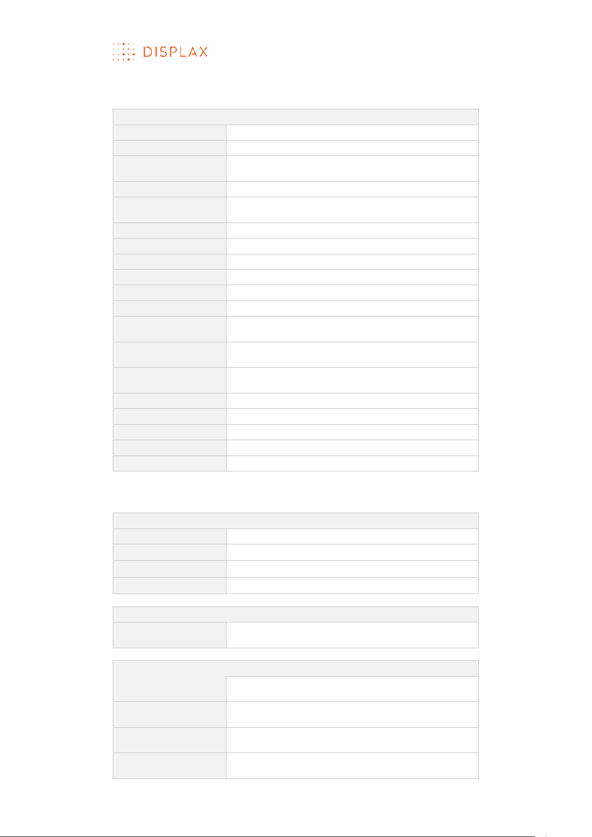
Specifications:
GENERAL
Detection method
Projected Capacitive Technology
Input method
Finger and gloved finger
Number of
simultaneous touches
40
Sensor thickness
100 micron transparent polymer
Noise Shielding
DISPLAX XTR-Shield™ Plus, a proprietary noise
filtering technology
Sizes
20’’ to 105’’
Aspect ratio
16:9, 4:3, custom formats
Controller
Printed circuit board with mini USB connector
Adhesive
Permanent, removable
Substrate
Float Glass, Gorilla Glass
Interface
HID
OS with multitouch
Windows 10, 8, 7*, Ubuntu 12.04, Linux**, Android**,
Chrome OS ***
OS with single touch
Mac OS X Yosemite (multitouch support through
TUIO bridge)
OS with mouse
emulation
Spinetix Media Player HMP 200, Samsung SSP D
Series
Data connectivity
USB 2.0
Touch accuracy
0,53% of sensor diagonal
Sensor weight
260 g
Controller weight
42 g
USB cable length
2 m
*Home Premium SP1; Professional SP1; Ultimate x64 SP1
** Depending on kernel and multitouch support.
*** 39.0.2171.85(64-bit)
PERFORMANCE
Substrate thickness
Up to 15 mm
Touch response
5 milliseconds
Finger separation
2,64% of sensor diagonal
Calibration
Available using control panel: no drift
POWER CONSUMPTION
Average power
consumption (P)
USB powered @ 5 V
Operation consumption: 250 mA
RELIABILITY
Operating
temperature range
-20 °C to 70 °C
Storage temperature
range
-40 °C to 135 °C
Operating humidity
range
0% to 96%
Storage humidity
range
0% to 100%, except controller
TECHNOLOGY FOR THE MULTITOUCH GENERATION
MKT.331.1 | DISPLAX SKIN FIT | DISPLAXTM MULTITOUCH TECHNOLOGIES 8
Touch Sensor life time
expectancy
Unlimited
Touch Controller life
time expectancy
1 million hours
Warranty
2 years
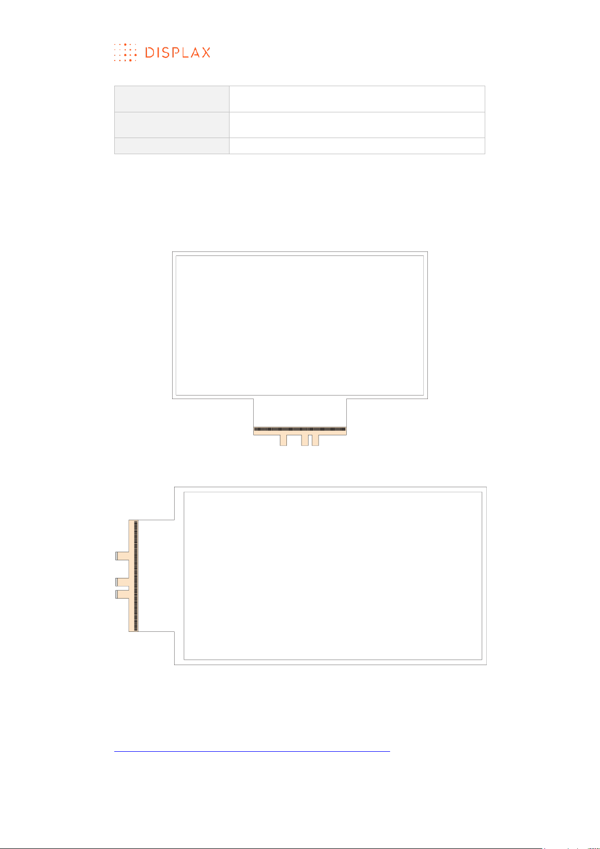
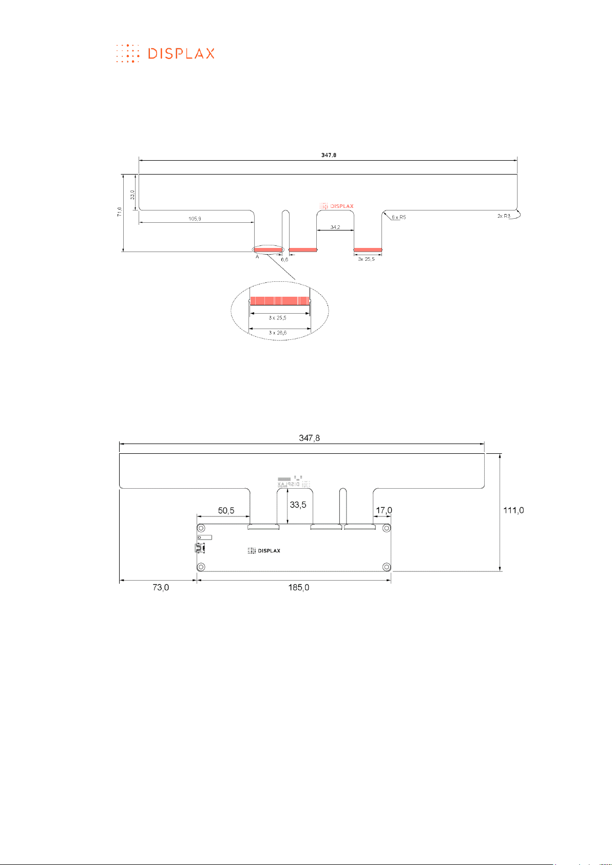
TOUCH SENSOR
The Touch Sensor is composed of a transparent polymer film with a
conductive grid and 1 polyester film Flexible Flat Cable.
Skin Fit – Touch Sensor, bottom tail version
Skin Fit – Touch Sensor, side tail version
For more information, refer to DISPLAX Skin Fit Standard Drawings document,
available for download in the following link:
http://login.displax.com/?op=20&id_item=4906&id_file=0
TECHNOLOGY FOR THE MULTITOUCH GENERATION
MKT.331.1 | DISPLAX SKIN FIT | DISPLAXTM MULTITOUCH TECHNOLOGIES 9
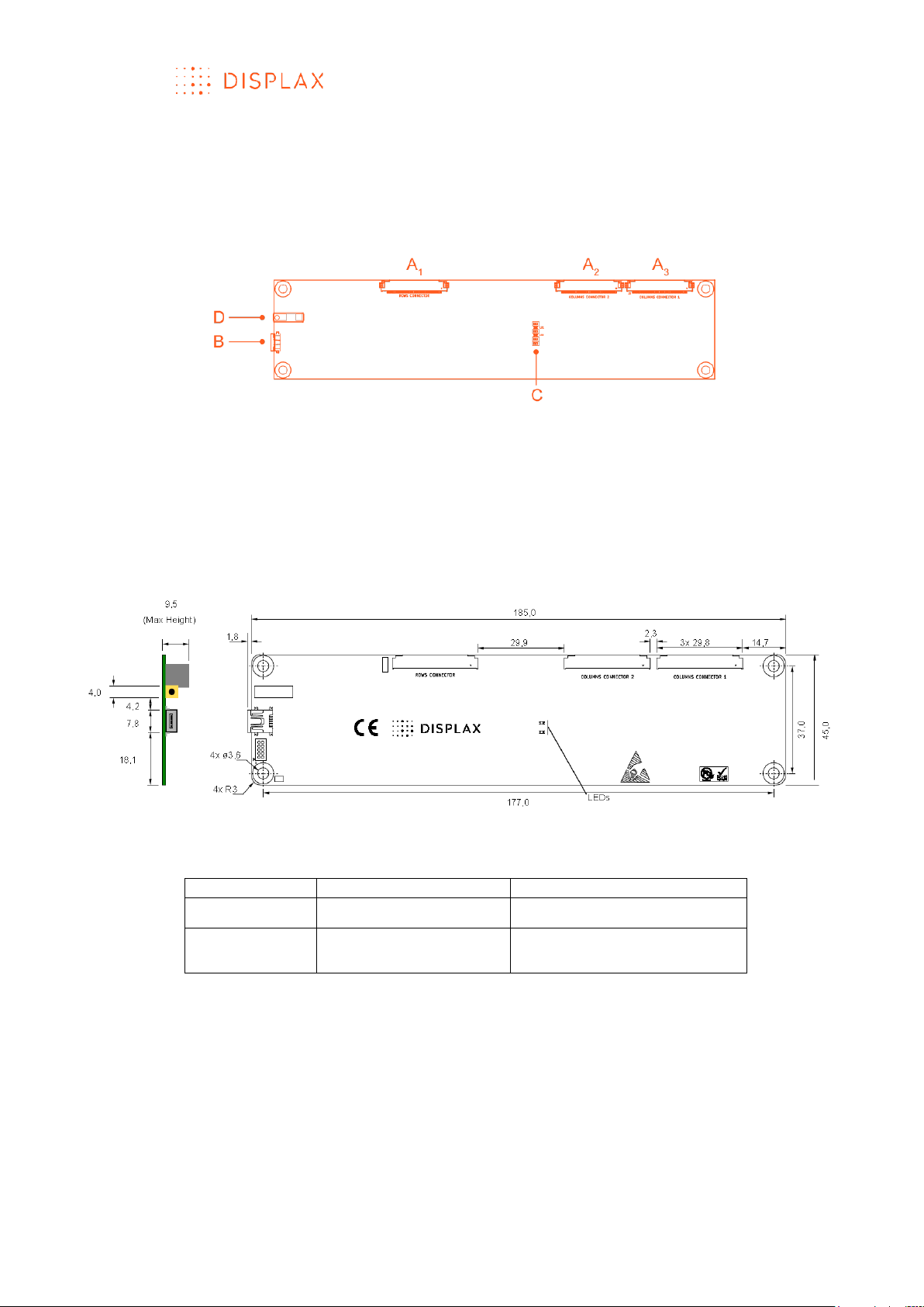
TOUCH CONTROLLER
The Touch Controller is a fiberglass board of 185 x 45 x 9,5mm.
The screw holes are M3 or M3.5.
A1 / A2 / A3– Flexible Flat Cable (FFC) Connector
B – Mini USB Port
C – LEDs
D – Ground cable port
Touch Controller dimensions:
Touch Controller led status
Led status
Normal Operation (HID)
Device Firmware Update
Red led
Fast blinking
On
Orange led
On with touch
Off without touch
Slow blinking
TECHNOLOGY FOR THE MULTITOUCH GENERATION
MKT.331.1 | DISPLAX SKIN FIT | DISPLAXTM MULTITOUCH TECHNOLOGIES 10
FLEXIBLE FLAT CABLE (FFC)
FFC dimensions:
INTEGRATION BETWEEN THE TOUCH CONTROLLER AND
THE FLEXIBLE FLAT CABLE (FFC)
TECHNOLOGY FOR THE MULTITOUCH GENERATION
MKT.331.1 | DISPLAX SKIN FIT | DISPLAXTM MULTITOUCH TECHNOLOGIES 11
UNPACK THE PRODUCT
OVERVI EW
This section provides a step by step guide on how to unpack the Skin product,
before its lamination.
Watch the unpacking video:
https://www.youtube.com/watch?v=ePth5KP0L8k
Note: Your product may present a different design from the one presented
in this user guide and instruction video.
RESOURCES NEEDED
A cutter and a clean plain table.
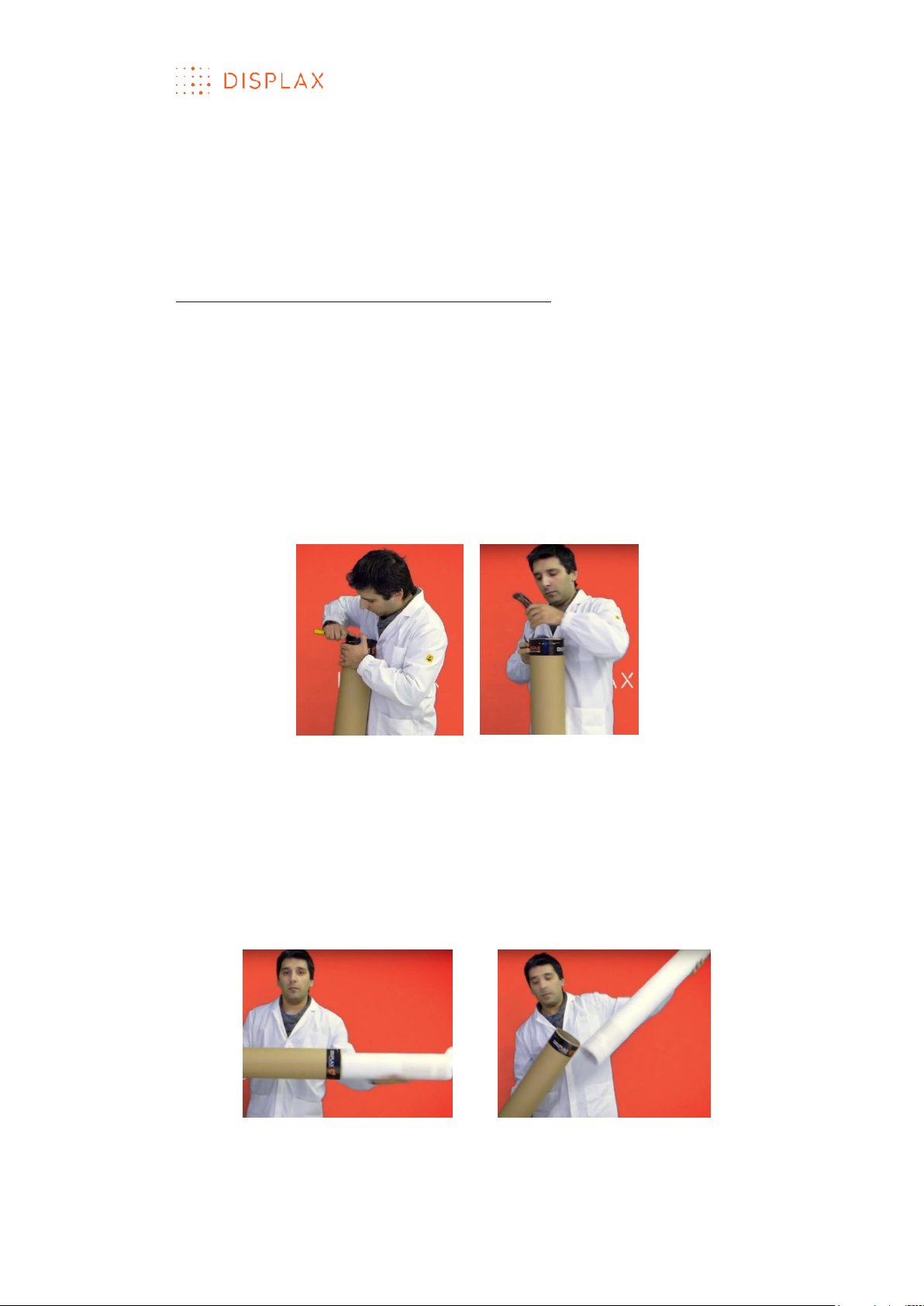
WORK PROCEDURE
1. Open the tube from the top side with the help of a cutter (Fig.1).
Fig.1
2. The touch sensor is wrapped around an inner tube inside the main tube.
Remove all the items inside the inner tube:
1. Touch controller(s);
2. USB and Ground cables;
3. Packing list.
3. Remove the inner tube (Fig.2):
Fig.2
TECHNOLOGY FOR THE MULTITOUCH GENERATION
MKT.331.1 | DISPLAX SKIN FIT | DISPLAXTM MULTITOUCH TECHNOLOGIES 12
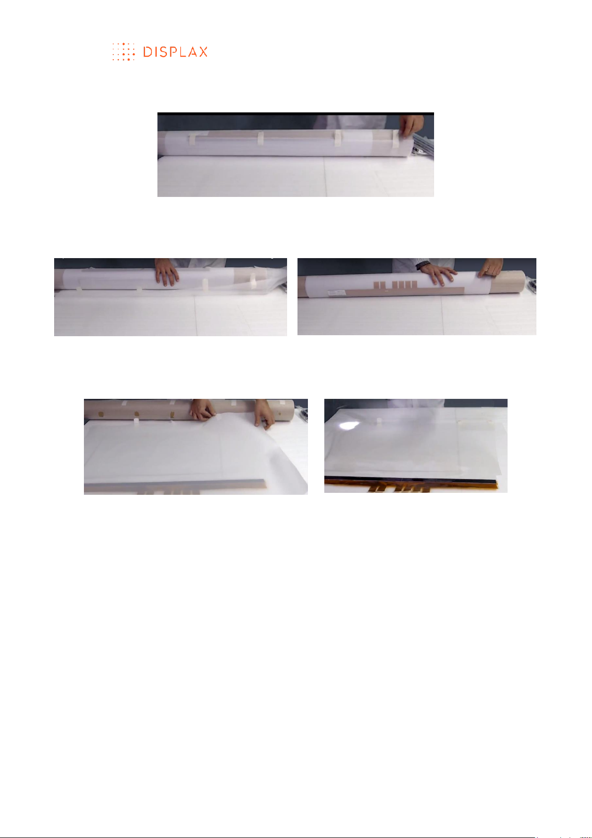
4. Unroll the Touch Sensor on top of a flat clean table (Fig. 3).
Fig. 3
a) Detach all the stickers to remove the foam layer (Fig.4);
b) Unroll the touch sensor over the table (Fig.5);
Fig.4
Fig.5
c) Detach the remaining stickers (Fig.6);
d) Free the unrolled touch sensor from the foam and other protection
layers (Fig.7).
Fig.6
Fig.7

TECHNOLOGY FOR THE MULTITOUCH GENERATION
MKT.331.1 | DISPLAX SKIN FIT | DISPLAXTM MULTITOUCH TECHNOLOGIES 13
LAMINATION
OVERVI EW
The Touch Sensor must be laminated on a non-conductive substrate, such as
glass, acrylic plate, corian, wood, mirror or other material, or surface where
we want to process multitouch recognition events.
The Touch Sensor of Skin Ultra has a permanent adhesive, which means that
after its lamination you cannot remove it and reuse it.
The Touch Sensor of Skin Fit and Skin Dualtouch is available in two versions:
permanent and removable.
The permanent version after lamination cannot be removed and reused.
The permanent version is the most common Touch Sensor version.
The removable version can be removed from the substrate where it has been
laminated and reapplied to a different substrate, as long as you remove it
gently and carefully to avoid damaging the Touch Sensor grid.
This section describes how to laminate the permanent and removable Touch
Sensor versions.
For the permanent version, a video has been created to enhance our
understanding of this procedure.
URL: https://www.youtube.com/watch?v=X4u-SKIjR9g
PERMANENT VERSION
OBJECTIVE
To laminate the Touch Sensor on a non-conductive substrate.
This description has been illustrated using ‘Glass’ but other non-conductive
substrates can be used.
PEOPLE REQUIRED
One person is required to perform the lamination on glass if the sensor has less
than 32 inches.
It is advisable involving a second person to support the lamination activities,
especially for Touch Sensors exceeding 32 inches. In this case, both persons
will pick up the Touch Sensor, one on each side, to avoid creasing and
tearing the sensor grid.
RESOURCES NEEDED
Before starting the Touch Sensor lamination, make sure you have the
following tools and equipment:
Soft cleaning lint free cloths;
Ethylic alcohol;
Dishwashing detergent with a neutral pH;
Distilled or bottled water;
Liquid sprayer, containing a solution with distilled or bottled water and
about 10% of the dishwashing detergent with a neutral pH, hereafter
referred as soapy water;
TECHNOLOGY FOR THE MULTITOUCH GENERATION
MKT.331.1 | DISPLAX SKIN FIT | DISPLAXTM MULTITOUCH TECHNOLOGIES 14
Squeegee;
X-acto or blade.
Scratch free surface to laminate the Touch Sensor on glass.
INSTALLATION PROCEDURE
The Touch Sensor must be handled carefully to avoid creasing or tearing.
Rippling may occur during delivery, but this will disappear during the
lamination process.
Always lay the Touch Sensor on a soft scratch free surface.
After unpacking the Touch Sensor, laminate it on a non-conductive substrate.
In here, the lamination process is illustrated using ‘Glass’.
To laminate the Touch Sensor, please refer to the following steps:
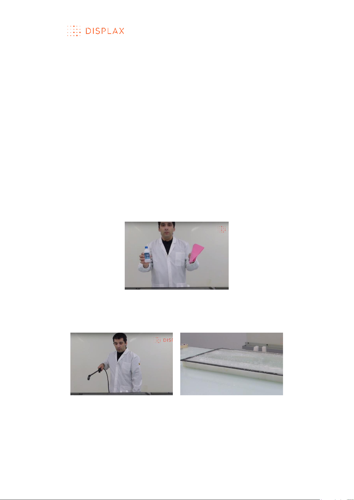
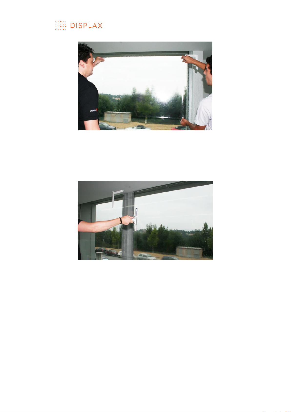
1. Clean the glass
Dirt and other contaminants allow pockets of air that undermine the
necessary seal for a good installation. Thoroughly clean the glass, with a lint
free cloth and ethylic alcohol, making sure it is free of dust, oils or grease
(Fig.1).
Fig.1
After cleaning the glass spray it with the mentioned solution containing
distilled or bottled water and about 10% of the dishwashing detergent with a
neutral pH (Fig.2).
Fig.2
TECHNOLOGY FOR THE MULTITOUCH GENERATION
MKT.331.1 | DISPLAX SKIN FIT | DISPLAXTM MULTITOUCH TECHNOLOGIES 15
Use a squeegee to remove the water (Fig.3),
Be sure that the glass is completely clean.
Fig.3
2. Peel off the Touch Sensor protection layer.
To peel off the Touch Sensor protection layer, you can either use:
a) a lamination wall, or
b) a clean and scratches free table.
In this work instruction a lamination wall has been used (Fig.4).
When using a table, the process is exactly the same but the operations are
executed in the horizontal position.
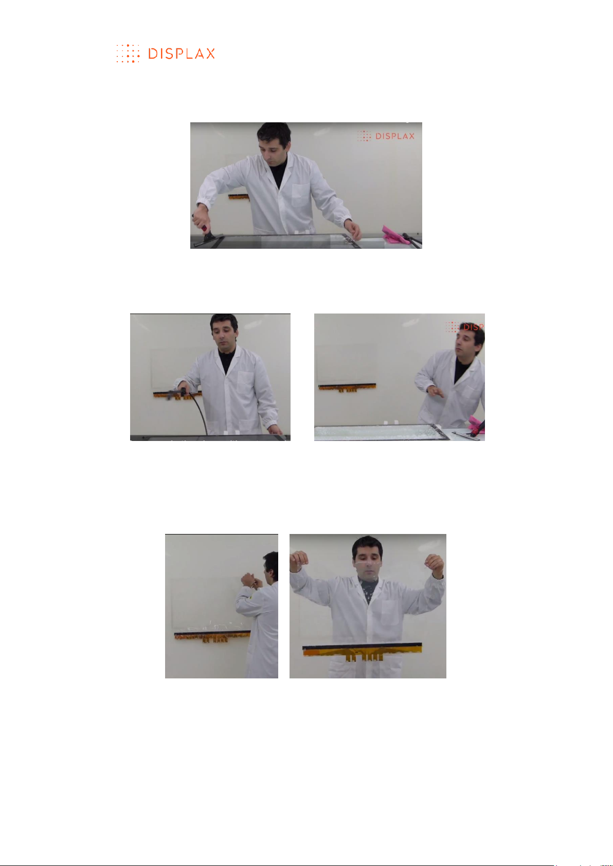
3. Wet the lamination wall with soapy water in order to adhere the Touch
Sensor to the wall (Fig.4)
Fig.4
Fig.5
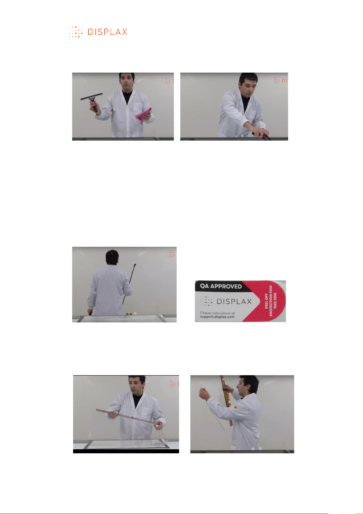
4. Pick the Touch Sensor and stick it to the lamination wall with the protection
layer facing the user view (Fig.6 and 7). This layer is the one which has a sticker
“QA APPROVED” (Fig.5), signaling the layer to be removed;
Fig.6
TECHNOLOGY FOR THE MULTITOUCH GENERATION
MKT.331.1 | DISPLAX SKIN FIT | DISPLAXTM MULTITOUCH TECHNOLOGIES 16
Fig.7
5. Apply soapy water to the Touch Sensor to ensure its adherence to the
lamination wall (Fig.8).
Fig.8
6. With a squeegee, remove some of the soapy water, to secure the sensor
on the lamination wall (Fig.9).
Fig.9
TECHNOLOGY FOR THE MULTITOUCH GENERATION
MKT.331.1 | DISPLAX SKIN FIT | DISPLAXTM MULTITOUCH TECHNOLOGIES 17
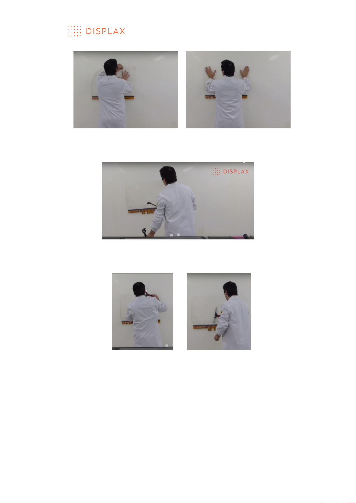
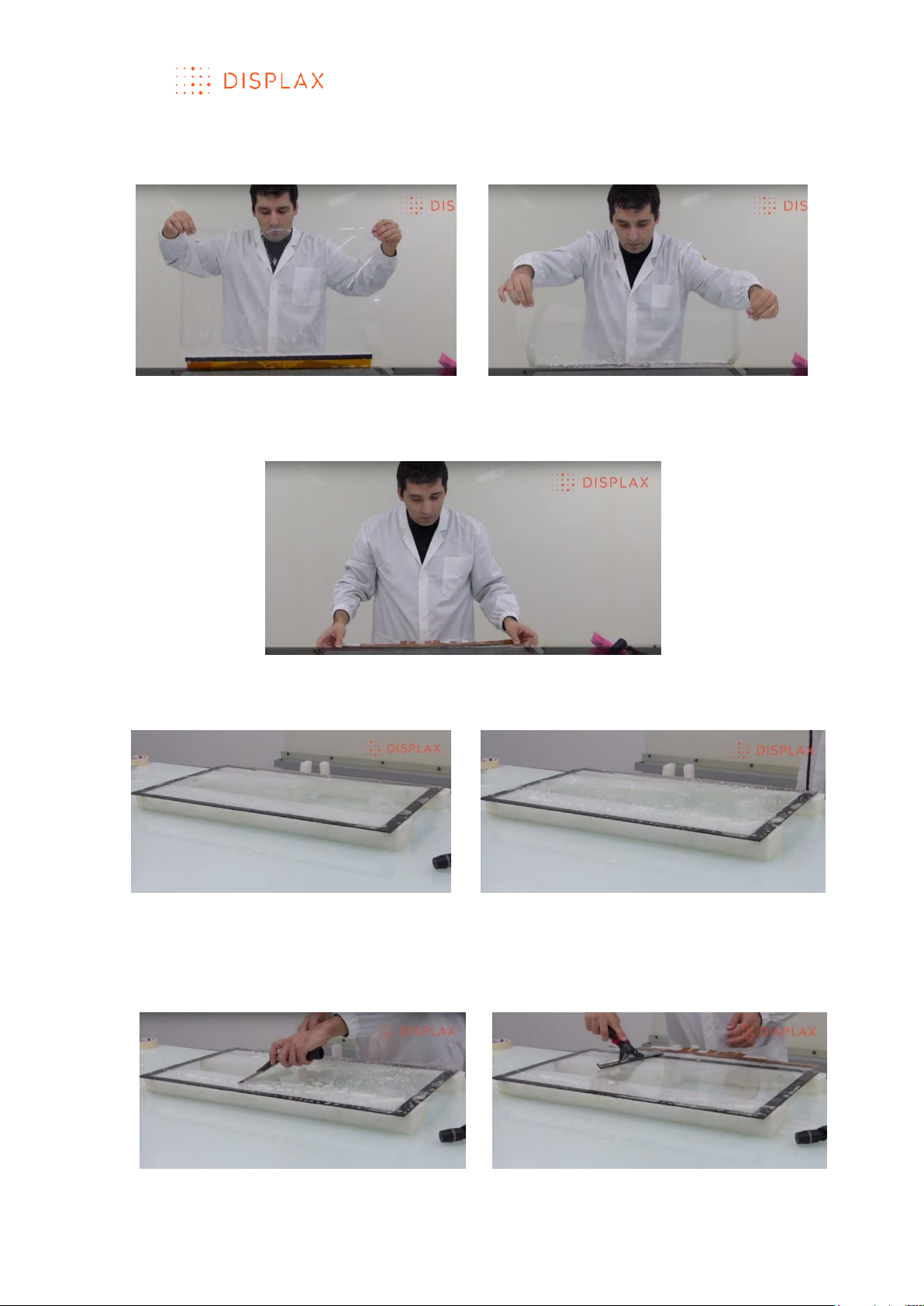
7. With the help of the “Quality approved” sticker remove the Touch Sensor
protection layer (Fig.10).
The “Quality approved” sticker is placed over one edge of the protection
layer and will help us lift and pell-off this protection cover.
Fig.10 With the help of the “Quality approved” sticker peel the Touch Sensor
protection layer
8. Pell-off the Touch Sensor protection layer while continuously spraying soapy
water and pulling-off the protection layer.
To perform this task, wet your fingers (Fig.11) and carefully release the
protection layer from the user side.
While you remove the protection layer, spray the adhesive surface with the
soapy water solution (Fig. 12, 13 and 14). It is important to pull back the liner
close to the Touch Sensor.
Fig.11 Be sure that your fingers are wet
Fig.12 Start peeling off the protection
layer by pulling the sticky tape
together with the protection layer
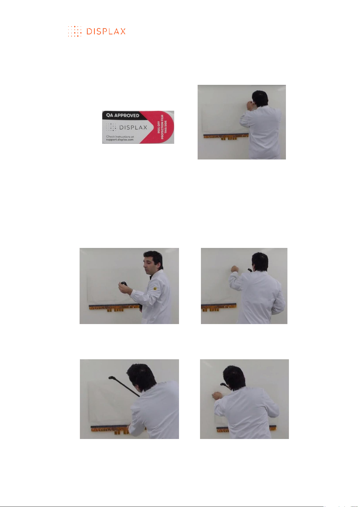
Fig.13 Gently pull the sensor protection layer while applying soapy water to the Touch
Sensor glue side
TECHNOLOGY FOR THE MULTITOUCH GENERATION
MKT.331.1 | DISPLAX SKIN FIT | DISPLAXTM MULTITOUCH TECHNOLOGIES 18
Fig.14 Pull the protection layer and apply soapy water until removing it completely.
9. Spray soapy water over the Touch Sensor glue area after removing its
protection (Fig.15)
Fig.15
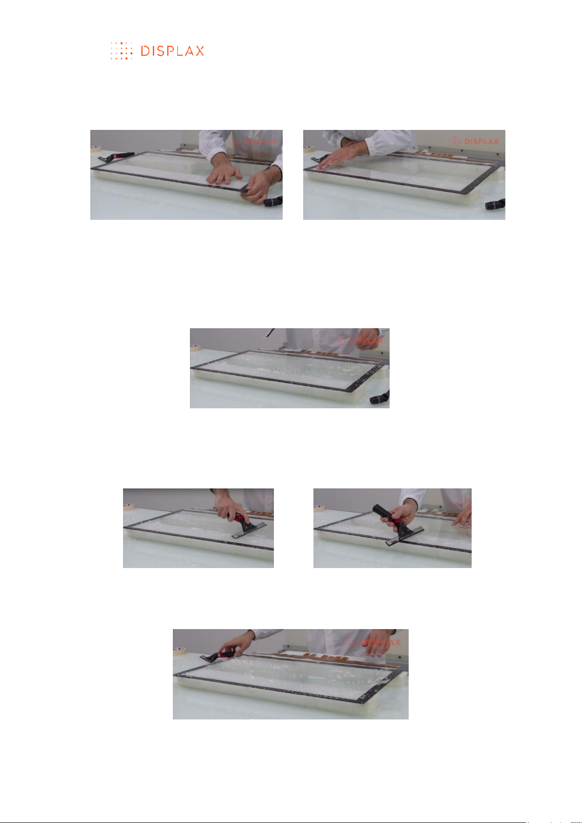
10. Spray soapy water over the glass where the Touch Sensor lamination will
be performed (Fig.16)
Fig.16
TECHNOLOGY FOR THE MULTITOUCH GENERATION
MKT.331.1 | DISPLAX SKIN FIT | DISPLAXTM MULTITOUCH TECHNOLOGIES 19
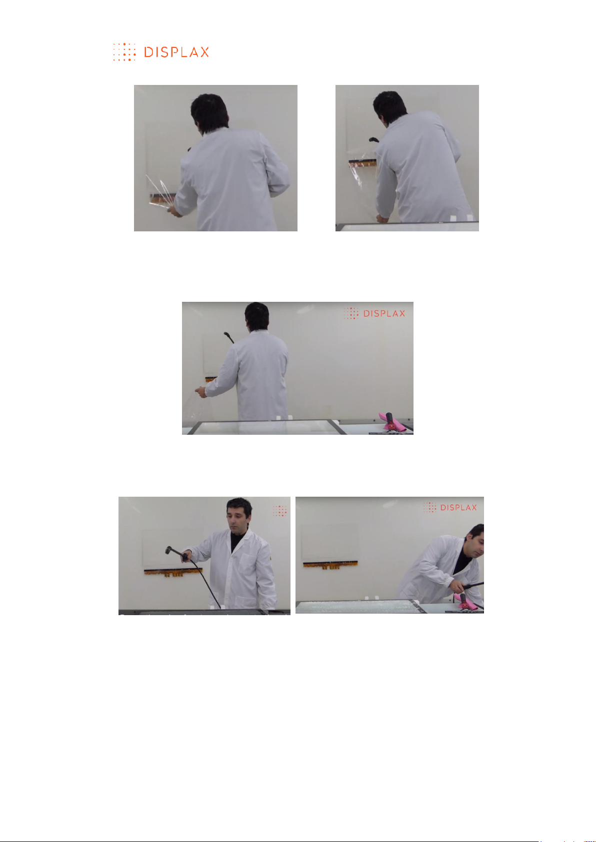
11. Clean the glass using a squeegee
Be sure that the glass is completely clean (Fig.17)
Fig.17
12. Before starting the Touch Sensor lamination spray the glass with soapy
water (Fig.18)
Fig.18
13. Carefully and gently detach the Touch Sensor from the lamination wall
(Fig.19)
If the Touch sensor has more than 32’’ two people may be required to avoid
creasing and tearing the sensor grid.
Fig.19
TECHNOLOGY FOR THE MULTITOUCH GENERATION
MKT.331.1 | DISPLAX SKIN FIT | DISPLAXTM MULTITOUCH TECHNOLOGIES 20
14. Position the Touch Sensor and apply its glue side on top of the wet glass
(Fig.20)
Fig.20
15. Gently and carefully align the Touch Sensor to the glass surface (Fig.21)
Fig.21
16. Spray the touch sensor on glass with soapy water (Fig.22)
Fig.22
17. Use the squeegee to laminate the Touch Sensor to the glass by lightly and
gently removing the soapy water, ensuring the Touch Sensor is correctly
positioned and without any dirt or particles (Fig.23)
Fig.23
TECHNOLOGY FOR THE MULTITOUCH GENERATION
MKT.331.1 | DISPLAX SKIN FIT | DISPLAXTM MULTITOUCH TECHNOLOGIES 21
19. Verify and gently adjust the margins of the Touch Sensor to the Glass
active area (Fig.24). The active area is the one in which we want to process
touch signals.
Fig.24
20. Again, for a 2nd time, spray the Touch Sensor on glass with soapy water
(Fig.25)
We should repeat the lamination process by applying once again soapy
water to the Touch Sensor on glass, but now we can apply more pressure to
the squeegee to remove the water and to ensure a more permanent
lamination.
Fig.25
21. Gently but with more pressure remove the soapy water with the
squeegee, to ensure a more consistent adhesion between the Touch Sensor
and the glass (Fig.26)
Fig.26
22. Again, for a 3rd time, spray the Touch Sensor on glass with soapy water
(Fig.27)
Fig.27
TECHNOLOGY FOR THE MULTITOUCH GENERATION
MKT.331.1 | DISPLAX SKIN FIT | DISPLAXTM MULTITOUCH TECHNOLOGIES 22
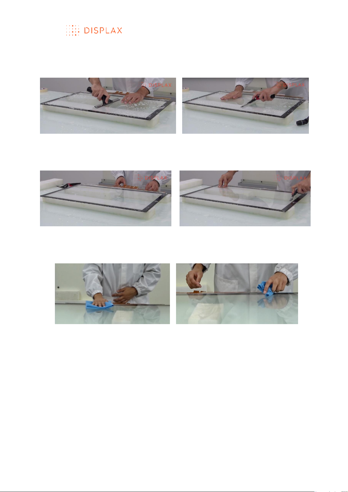
23. With a little more pressure remove the soapy water with the squeegee to
ensure a permanent adhesion between the glass and the Touch Sensor
(Fig.28)
Fig.28
24. If needed, repeat the process one last time: apply the soapy water and
remove it with the squeegee (Fig.29)
Fig.29
25. After the lamination process you can gently pass a clean lint free cloth all
over the laminated product to remove remaining water (Fig.30)
Fig.30
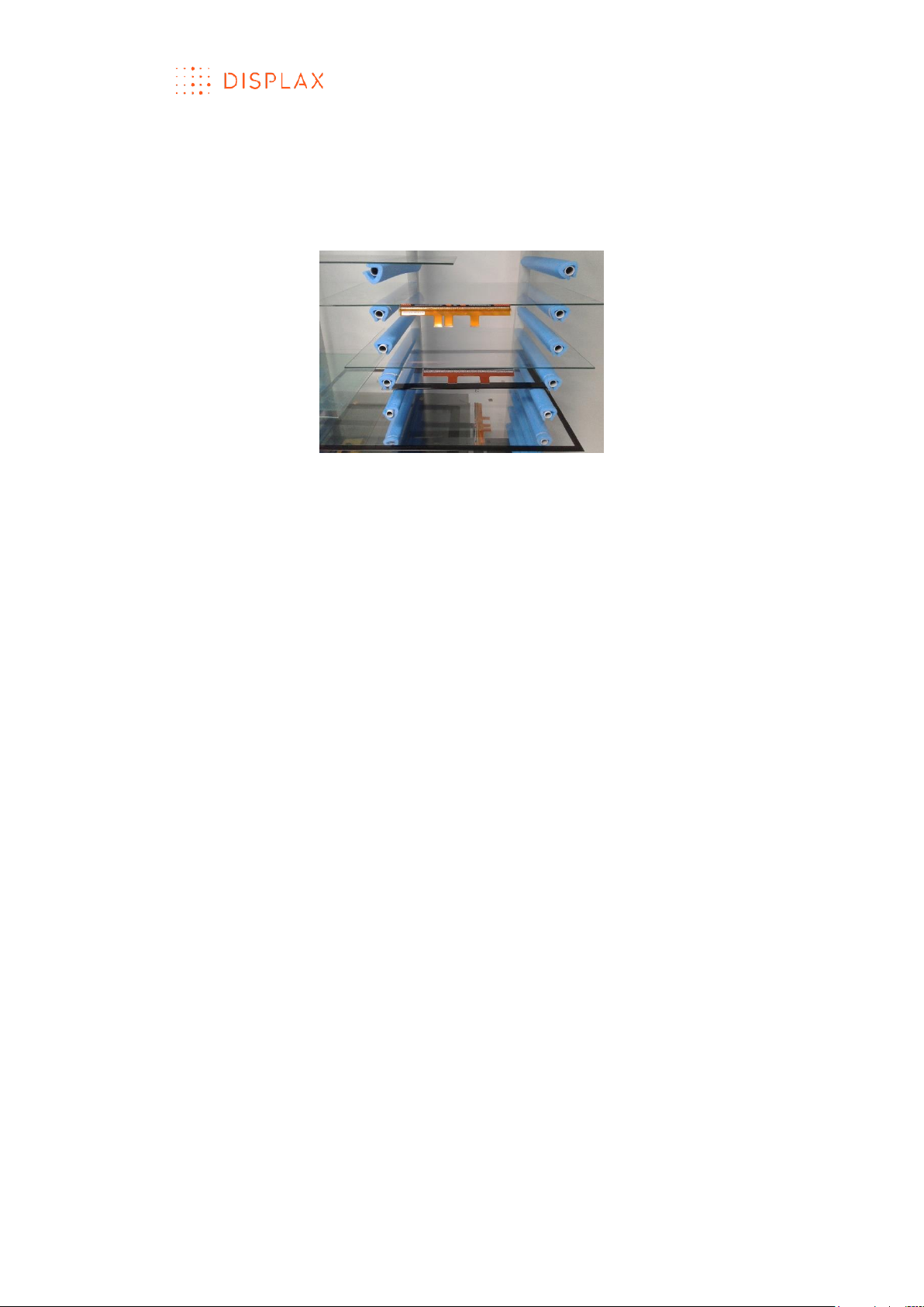
26. Leave the Touch Sensor laminated on glass drying for 24 hours (Fig.31)
If water bubbles remain between the Touch Sensor and the glass, do not be
tempted to force them out. These bubbles should evaporate during the 24
hours drying period.
If feasible the drying area should have air conditioning to control and monitor
the air heat and humidification levels:
a) The temperature of the air should be between 20 and 25 ºC;
b) The humidity level should be between 30% and 45%;
c) The drying time should be of 24 hours.
TECHNOLOGY FOR THE MULTITOUCH GENERATION
MKT.331.1 | DISPLAX SKIN FIT | DISPLAXTM MULTITOUCH TECHNOLOGIES 23
The drying area should have a structure to place the Touch Sensor on glass.
This structure, should have a foam covering or coating the areas where the
glass will be in contact with the support structure parts. Fig.31 depicts this
condition, we can see a foam covering the areas in contact with the glass
and/or Touch Sensor.
Fig.31
Once the Touch Sensor is dry you can connect it to the Touch Controller.
LAMI NATION QUALITY
BEFORE DRYING
1. Misalignment between the glass and the laminated Touch Sensor
Edge and squareness misalignment between the glass and the Touch Sensor
are permissible but we recommend that they do not exceed a tolerance
interval between 1 and 2 mm for Touch Sensors between 20 and 50 inches
and between 1 and 4 mm for Touch Sensors between 51and 105 inches. A
posteriori, this misalignment can be compensated by running the Touch
Controller software on which we can define the Active Touch Sensor area to
perform the Touch Sensor geometrical calibration.
2. Overall lamination quality
Bubbles are permissible as long as they are deemed to disappear per
evaporation after the drying period.
Bubbles, coiled hair and lint, blemishes, contaminations and scratches are
not permissible.
Scratches on the Touch Sensor active area (which will be visible to the user)
may be permissible if they are very thin, no more than 5 millimetres long and
with a thickness of about 15 microns, unless the client defines other quality
requirements.
AFTER DRYING
Bubbles, coiled hair and lint, blemishes, contaminations and scratches are
permissible if they will be covered by the LCD or other display borders.
Scratches on the Touch Sensor visible area may be permissible if they are very
thin, making them imperceptible among the Touch Sensor grid, and they do
not exceed three occurrences, unless the client defines other quality
requirements.

TECHNOLOGY FOR THE MULTITOUCH GENERATION
MKT.331.1 | DISPLAX SKIN FIT | DISPLAXTM MULTITOUCH TECHNOLOGIES 24
CLEANING THE LAMINATED TOUCH SENSOR BEFORE
INTEGRATION
Clean the laminated product comprising the Glass and the Touch Sensor
before its integration on a LCD or other Display.
Carefully clean the glass, and gently clean the Touch Sensor making sure no
finger print, dirt or other contaminant are left.
Use a soft cleaning lint free cloth previously wet with soapy water, and clean
both sides.
Proceed with a visual inspection to ensure that no finger print, dirt or other
contaminant is left.
The glass with the Touch Sensor shall be inspected and verified on both sides
at a close distance of about one foot with good quality ambient light.
REMOVABLE VERSION
The removable version does not have a protective layer to be removed
exposing the glue like on the permanent version.
In the removable version, the Touch Sensor must be laminated over a
backing adhesive provided with the Skin Fit or Skin Dualtouch product.
This backing adhesive, named “cling”, is a transparent polymer, which must
be applied over a determined substrate, like glass. In this description, we refer
to ‘glass’, but other non-conductive substrates can also be used.
Clean the glass, proceeding in the same way as described in step 1of the
permanent version, to ensure the glass is duly clean without any dirt, lint,
finger-tip or other contaminant, then you should decide on the correct
position to place the “Cling” over the glass.
To ensure the “Cling” adhesion to the glass spray soapy water all over the
glass where you want to laminate the “Cling”.
The “cling” is provided with a white protective substrate, which must be
removed (Fig.1). The exposed area must be placed facing the glass,
previously wet with soapy water, where we want to laminate the Touch
Sensor (Fig.2).
Fig.1 Carefully remove the white protection
TECHNOLOGY FOR THE MULTITOUCH GENERATION
MKT.331.1 | DISPLAX SKIN FIT | DISPLAXTM MULTITOUCH TECHNOLOGIES 25
Fig.2 Place the “Cling” against the glass, previously wet with soapy water, where
we want to laminate the Touch Sensor
Having the “Cling” over the glass, apply soapy water all over the “Cling” and
use a squeegee to clean and to laminate the “Cling” onto the glass, repeat
this process of applying soapy water and removing it with the squeegee for
another two times, making more pressure at each time to ensure the
adhesion of the “Cling” onto the glass. (Fig.3).
Fig.3 Apply soapy-water over the “Cling” to clean it and also to ensure its
adherence to the glass
The “Cling” by now should be laminated and free of any particles, finger-tips,
lint or other contaminant, and should be without any crease or bubble.
Having the “Cling” laminated onto the glass, we can now laminate the Touch
Sensor onto the “Cling”.
Carefully and gently clean the Touch Sensor using a soft cleaning lint free
cloth previously wet with soapy water, then proceed with a visual inspection
to ensure that no finger print, dirt or other contaminant is present.
To laminate the Touch Sensor over the “Cling” the steps are similar to the ones
described in the permanent version (see steps 15 to 26 of the permanent
lamination), those steps consist on:
1. Applying soapy water over the “Cling” on glass;
2. Positioning and placing the Touch Sensor over the “Cling” on glass;

TECHNOLOGY FOR THE MULTITOUCH GENERATION
MKT.331.1 | DISPLAX SKIN FIT | DISPLAXTM MULTITOUCH TECHNOLOGIES 26
3. Aligning the Touch Sensor active area with the area of the “Cling” on
glass;
4. Applying soapy water over the Touch Sensor;
5. Removing the soapy water with a squeegee to ensure the progressive
adhesion between the Touch Sensor and the “Cling” on glass;
6. Repeating for another two times the previous step, of applying soapy
water and removing it with the squeegee, but when doing it for a second
and third time more pressure should be applied at each term, to ensure
the Touch Sensor adhesion onto the “Cling” laminated on glass;
7. Carefully drying the laminated Touch Sensor surface and the area around
it;
8. Letting the laminated product to dry for a 24-hour period.
Once the Touch Sensor is dry you can connect it to the Touch Controller.
The same lamination quality parameters are applied to the permanent and
to the removable versions, see the above sections “Lamination quality” and
“Cleaning the laminated Touch Sensor before its integration on an LCD”.
To reuse the “Cling” and the “Touch Sensor” in another surface, they both
must be removed and handled gently and carefully.
Start by removing the Touch Sensor by lifting its edges and progressively lifting
the whole Touch Sensor.
After removing the Touch Sensor, remove the “Cling” from the glass by lifting
its edges and progressively detaching it from the glass.
Both the “Touch Sensor” and the “Cling” after its removal must be handled
carefully and gently to be reused in another substrate. We recommend
placing each component, the “Cling” and the “Touch Sensor” on individual
vegetable paper covered with foam.
To reuse the product components, please refer to the above described
procedure, but this time you will not have to remove the “Cling” white
protection substrate since it has already been removed in the first
application.
We do not recommend removing the cling more than two times, although a
third time might be possible depending on different handling, substrates, and
operational and environmental conditions. If the cling gets damaged, you
should replace the cling for a new one.
PRODUCT SERI AL NUMBER
The Touch Sensor serial number is placed on the left side of the FFCs.
The Touch Controller serial number is placed on its back.
The product package also has the same serial number.
TECHNOLOGY FOR THE MULTITOUCH GENERATION
MKT.331.1 | DISPLAX SKIN FIT | DISPLAXTM MULTITOUCH TECHNOLOGIES 27
INTEGRATION GUIDE
A video has been created to support the integration process:
URL: https://academy.displax.com/knowledgebase/integration/
Your product may present a different design from the one presented in this
user guide and instruction video.
Note:
This guide assumes you already have the Touch Sensor laminated on glass.
For more information on how to laminate, please refer to the lamination
guide.
MOUNTI NG THE GL ASS WITH THE TOUCH SENSOR ON A DISPLAY
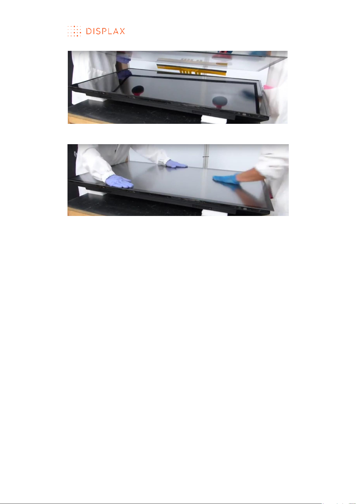
Clean the LCD and the glass on which the Touch Sensor has been laminated.
Use a soft wet lint free cloth with dishwasher detergent to clean the glass. The
same solution can be used to clean the Touch Sensor, which should be
cleaned with care to avoid damaging the sensor electrodes, the flat flexible
cable and its solder joints.
To mount the glass with the Touch Sensor on the LCD apply foam gasket or a
double sided bonding tape (Fig.2) around the perimeter of the LCD to ensure
an air gap between the LCD and the Touch Sensor. An air gap is advisable
to reduce electromagnetic interferences from the LCD panel. The air gap
may vary between 1 to 10 mm, a bigger air gap makes the Touch Sensor less
sensitive to electromagnetic interferences. We recommend using an air gap
of at least 2 mm.
The foam gasket or double sided bounding tape should be non-sulphurous
and must maintain its adhesion properties at any temperature that the LCD
may be experiencing in normal use.
Fig.1
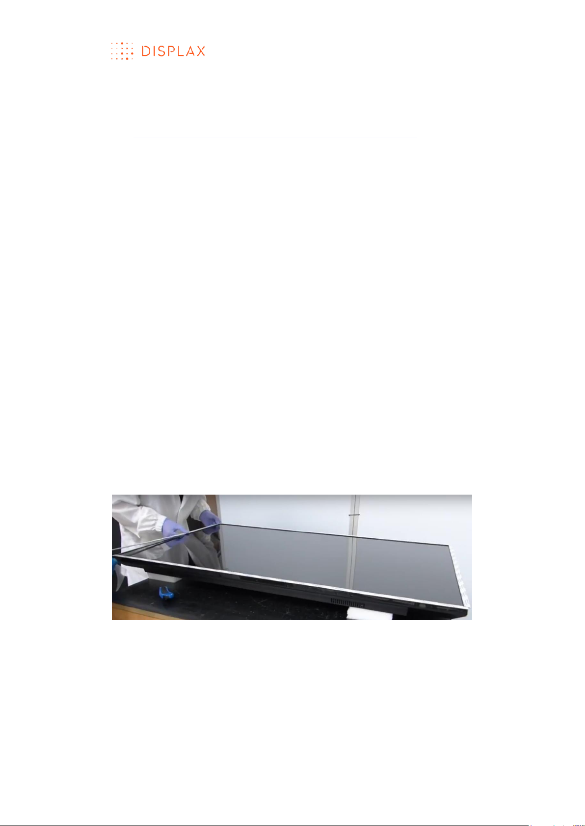
Having applied the foam gasket, place the laminated Touch Sensor over the
LCD panel with the Touch Sensor facing the LCD (Fig.2 and 3).
TECHNOLOGY FOR THE MULTITOUCH GENERATION
MKT.331.1 | DISPLAX SKIN FIT | DISPLAXTM MULTITOUCH TECHNOLOGIES 28
Fig.2
Fig.3
When positioning the laminated Touch Sensor over the LCD, carefully align
the active area of the LCD with the active area of the Touch Sensor
laminated on glass, also take into consideration the position of the flexible
cables to ensure the best alignment for mounting the PCB controller on the
back of the LCD.
Likewise, take into account that the backlight of the LCD is usually the noisiest
part. Traditionally, this component is placed in one of the sides of the display.
If your Touch Sensor is a side tail version, the sensor side where the PCB
Controller attaches should be on the same side of the LCD backlight since
the signal is stronger here, thus minimizing the impact of the noise from the
backlight. Contact your LCD manufacturer for more information regarding
the backlight location.
TECHNOLOGY FOR THE MULTITOUCH GENERATION
MKT.331.1 | DISPLAX SKIN FIT | DISPLAXTM MULTITOUCH TECHNOLOGIES 29
INTEGR ATING THE TO UCH CONTROLLER
To open the Touch Controller protection air bag, pierce the bag, using a
blade to release its air to make it easier to remove it in safety (Fig.4 and 5).
Fig.4
Fig.5
Define the position to secure the Touch Controller to the LCD (Fig.6).
Fig.6
When defining the Touch Controller position:
a) Make sure the flexible cable reaches comfortably the Touch Controller
(PCB);
b) Make sure there is a good access to the USB cable in that location;
c) Identify a grounding option for the Touch Controller;
d) Avoid, when possible, placing the Touch Controller near the LCD power
source.
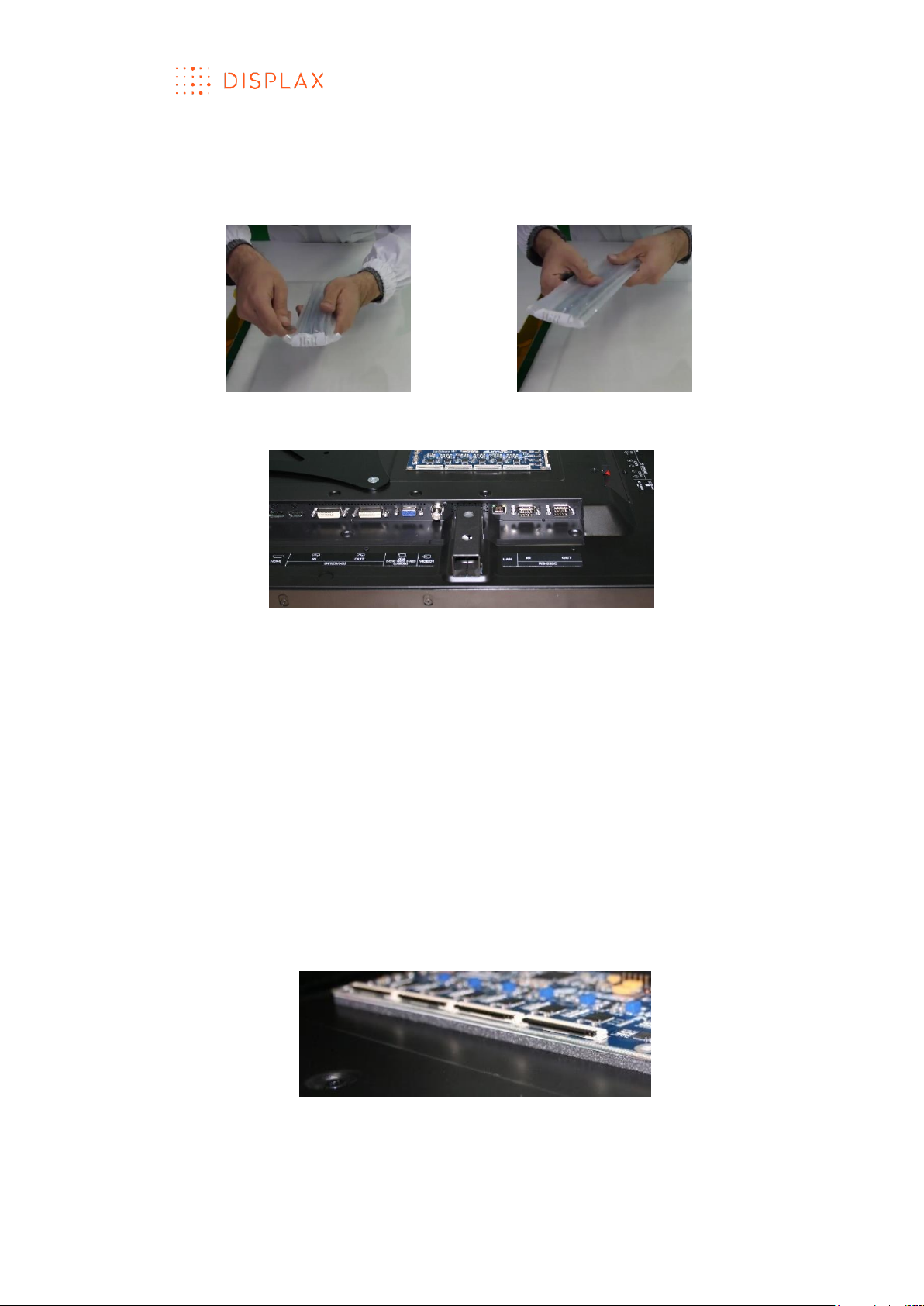
Touch Controller integration - attach the Touch Controller to the back of the
LCD:
a) The Touch Controller cannot be directly placed on metal;
b) Use foam gasket or a double sided bonding tape to attach the Touch
Controller to the back of the LCD (Fig.7). The gasket must maintain its
adhesion properties at any temperature that the LCD may be
experiencing in normal use.
Fig.7
c) Make sure to have a minimum distance of 3 mm from the Touch
Controller to the LCD, to ensure that the electromagnetic noise from the
LCD doesn’t affect it. This distance can be created either by placing a
gasket under the Touch Controller, as previously described, or by using
TECHNOLOGY FOR THE MULTITOUCH GENERATION
MKT.331.1 | DISPLAX SKIN FIT | DISPLAXTM MULTITOUCH TECHNOLOGIES 30
metal standoffs connected to the LCD chassis above which the Touch
Controller can be placed and attached using screws threaded into the
metal standoffs. This procedure grounds the Touch Controller.
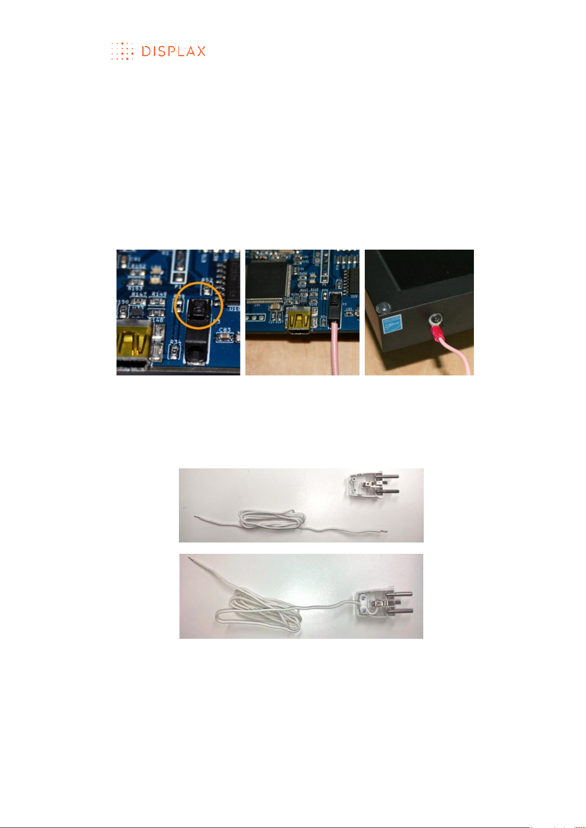
d) Ground the Touch Controller, either by using screws threaded into the
LCD metal chassis or by using the low impedance grounding cable
supplied with the Skin product which must be connected to the Touch
Controller socket (Fig.8 and 9) and to a metal part of the LCD chassis
(Fig.10). To connect the ground cable to the Touch Controller insert its
ending tip into the socket, and make sure it does stay securely fixed. Later
if you want to remove the ground cable from its socket use a tip of a pen
or a paper clip to unlock the ground cable connector (Fig.8 and 9).
Fig.8
Fig.9
Fig.10
e) In some applications the LCD may only have a plastic casing and
grounding to the LCD chassis is not an option. Other times the LCD
electricity plug doesn’t ground. In these cases, use the power socket to
ground the Touch Controller. Make sure there is a good access to the
ground cable (Fig.11 and 12).
Fig.11
Fig.12
 Loading...