


SERVICE MANUAL
Design and specifications are subject to change without notice.
COLOR TELEVISION RECEIVER
DT1900-P-A
ORIGINAL
MFR’S VERSION A
6. AVOID AN X-RAY1. KEEP THE NOTICES
5. TAKE CARE TO DEAL WITH THE
CATHODE-RAY TUBE
In the condition that an explosion-proof cathoderay tube is set in this equipment, safety is
secured against implosion. However, when
removing it or serving from backward, it is
dangerous to give a shock. Take enough care to
deal with it.
Safety is secured against an X-ray by considering about the cathode-ray tube and the high
voltage peripheral circuit, etc.
Therefore, when repairing the high voltage peripheral circuit, use the designated parts and
make sure not modify the circuit.
Repairing except indicates causes rising of high
voltage, and it emits an X-ray from the cathoderay tube.
Inferior silicon grease can damage IC's and transistors.
When replacing an IC's or transistors, use only specified silicon grease (YG6260M).
Remove all old silicon before applying new silicon.
IMPORTANT
SERVICING NOTICES ON CHECKING
As for the places which need special attentions,
they are indicated with the labels or seals on the
cabinet, chassis and parts. Make sure to keep the
indications and notices in the operation manual.
2. AVOID AN ELECTRIC SHOCK
There is a high voltage part inside. Avoid an
electric shock while the electric current is
flowing.
3. USE THE DESIGNATED PARTS
The parts in this equipment have the specific
characters of incombustibility and withstand
voltage for safety. Therefore, the part which is
replaced should be used the part which has
the same character.
Especially as to the important parts for safety
which is indicated in the circuit diagram or the
table of parts as a mark, the designated
parts must be used.
PUT PARTS AND WIRES IN THE
ORIGINAL POSITION AFTER
ASSEMBLING OR WIRING
4.
There are parts which use the insulation
material such as a tube or tape for safety, or
which are assembled in the condition that
these do not contact with the printed board.
The inside wiring is designed not to get closer
to the pyrogenic parts and high voltage parts.
Therefore, put these parts in the original
positions.
7.PERFORM A SAFETY CHECK AFTER
SERVICING
Confirm that the screws, parts and wiring which
were removed in order to service are put in the
original positions, or whether there are the
portions which are deteriorated around the
serviced places serviced or not. Check the
insulation between the antenna terminal or
external metal and the AC cord plug blades.
And be sure the safety of that.
(INSULATION CHECK PROCEDURE)
1.
2.
3.
4.
Unplug the plug from the AC outlet.
Remove the antenna terminal on TV and turn
on the TV.
Insulation resistance between the cord plug
terminals and the eternal exposure metal
[Note 2] should be more than 1M ohm by
using the 500V insulation resistance meter
[Note 1].
If the insulation resistance is less than 1M
ohm, the inspection repair should be
required.
[Note 1]
If you have not the 500V insulation
resistance meter, use a Tester.
[Note 2]
External exposure metal: Antenna terminal
Earphone jack
A1-1
Please include the following informations when you order parts. (Particularly the VERSION LETTER.)
1. MODEL NUMBER and VERSION LETTER
The MODEL NUMBER can be found on the back of each product and the VERSION LETTER can be
found at the end of the SERIAL NUMBER.
2. PART NO. and DESCRIPTION
You can find it in your SERVICE MANUAL.
HOW TO ORDER PARTS
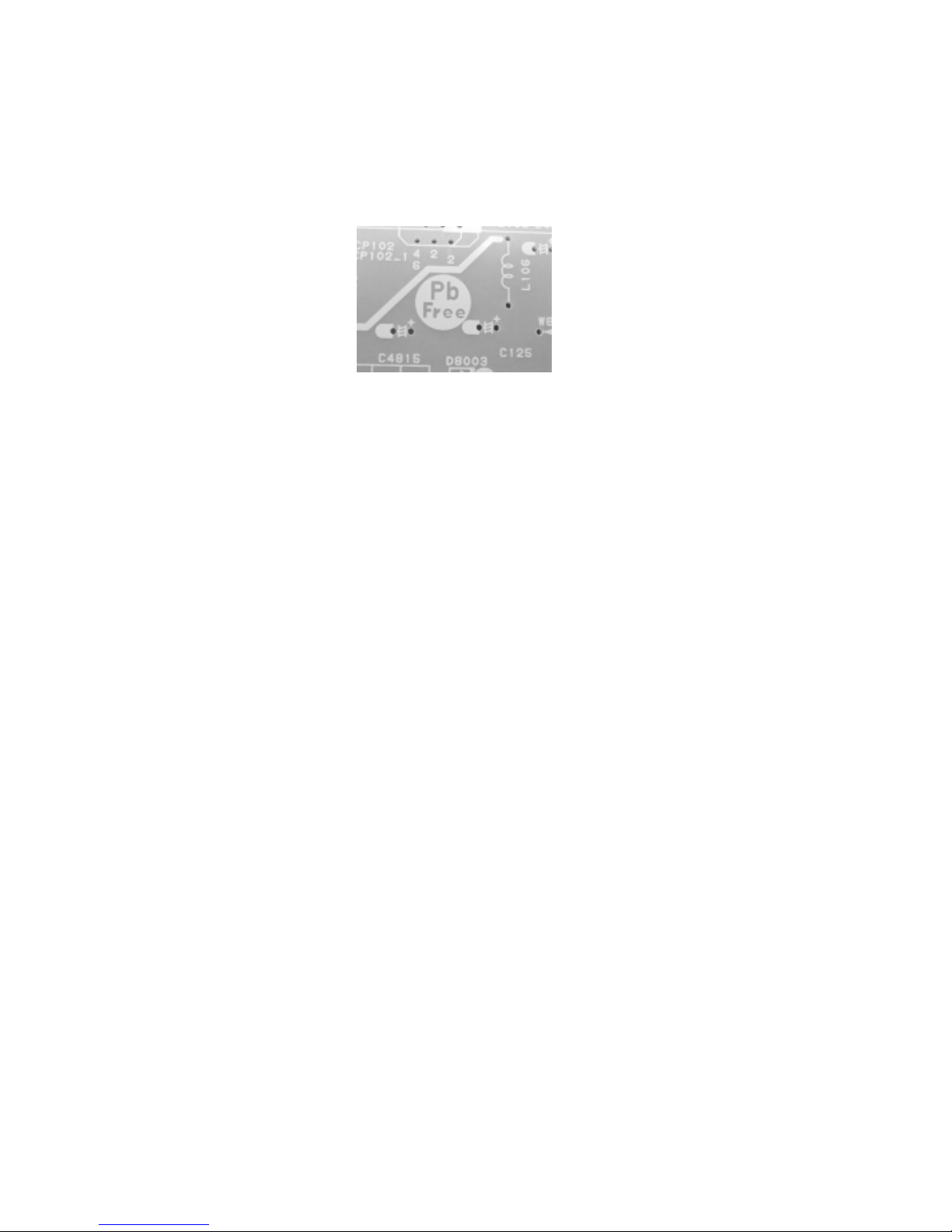
PCBs (manufactured) using lead free solder will have a PbF printing on the PCB.
(Please refer to figures.)
Caution:
Pb free solder has a higher melting point than standard solder;
Typically the melting point is 86°F~104°F(30°C~40°C) higher.
Please use a soldering iron with temperature control and adjust it to 650°F ± 20°F (350°C ± 10°C).
In case of using high temperature soldering iron, please be careful not to heat too long.
Pb free solder will tend to splash when heated too high (about 1100°F/ 600°C).
All products with the printed circuit board with PbF printing must be serviced with lead free solder.
When soldering or unsoldering, completely remove all of the solder from the pins or solder area,
and be sure to heat the soldering points with the lead free solder until it melts sufficiently.
Distinction of PbF PCB:
Recommendations
Recommended lead free solder composition is Sn-3.0Ag-0.5Cu.
ABOUT LEAD FREE SOLDER (PbF)
•
•
•
A1-2

A1-1
A1-1
A1-1
A1-2
A2-1
A3-1~A3-4
B1-1
B2-1, B2-2
C-1
C-1
C-1
D-1~D-5
E-1, E-2
F-1~F-4
G-1, G-2
G-3, G-4
G-5, G-6
G-7, G-8
G-9, G-10
H-1, H-2
I-1
J1-1
J2-1, J2-2
CONTENTS
A2-1
SERVICING NOTICES ON CHECKING ...........................................................................................................
HOW TO ORDER PARTS .................................................................................................................................
IMPORTANT .....................................................................................................................................................
ABOUT LEAD FREE SOLDER (PbF)............................................................................................................
CONTENTS ......................................................................................................................................................
GENERAL SPECIFICATIONS ..........................................................................................................................
DISASSEMBLY INSTRUCTIONS
1. REMOVAL OF ANODE CAP...................................................................................................................
2. REMOVAL AND INSTALLATION OF FLAT PACKAGE IC ......................................................................
SERVICE MODE LIST.......................................................................................................................................
CONFIRMATION OF HOURS USED ................................................................................................................
WHEN REPLACING EEPROM (MEMORY) IC .................................................................................................
ELECTRICAL ADJUSTMENTS .........................................................................................................................
BLOCK DIAGRAM .............................................................................................................................................
PRINTED CIRCUIT BOARDS
MAIN/CRT/OPERATION/FRONT JACK........................................................................................................
SCHEMATIC DIAGRAMS
MICON/TUNER..............................................................................................................................................
CHROMA .......................................................................................................................................................
TV POWER....................................................................................................................................................
DEFLECTION/CRT ........................................................................................................................................
SOUND/AV ....................................................................................................................................................
WAVEFORMS ....................................................................................................................................................
MECHANICAL EXPLODED VIEW .....................................................................................................................
MECHANICAL REPLACEMENT PARTS LIST..................................................................................................
ELECTRICAL REPLACEMENT PARTS LIST ...................................................................................................
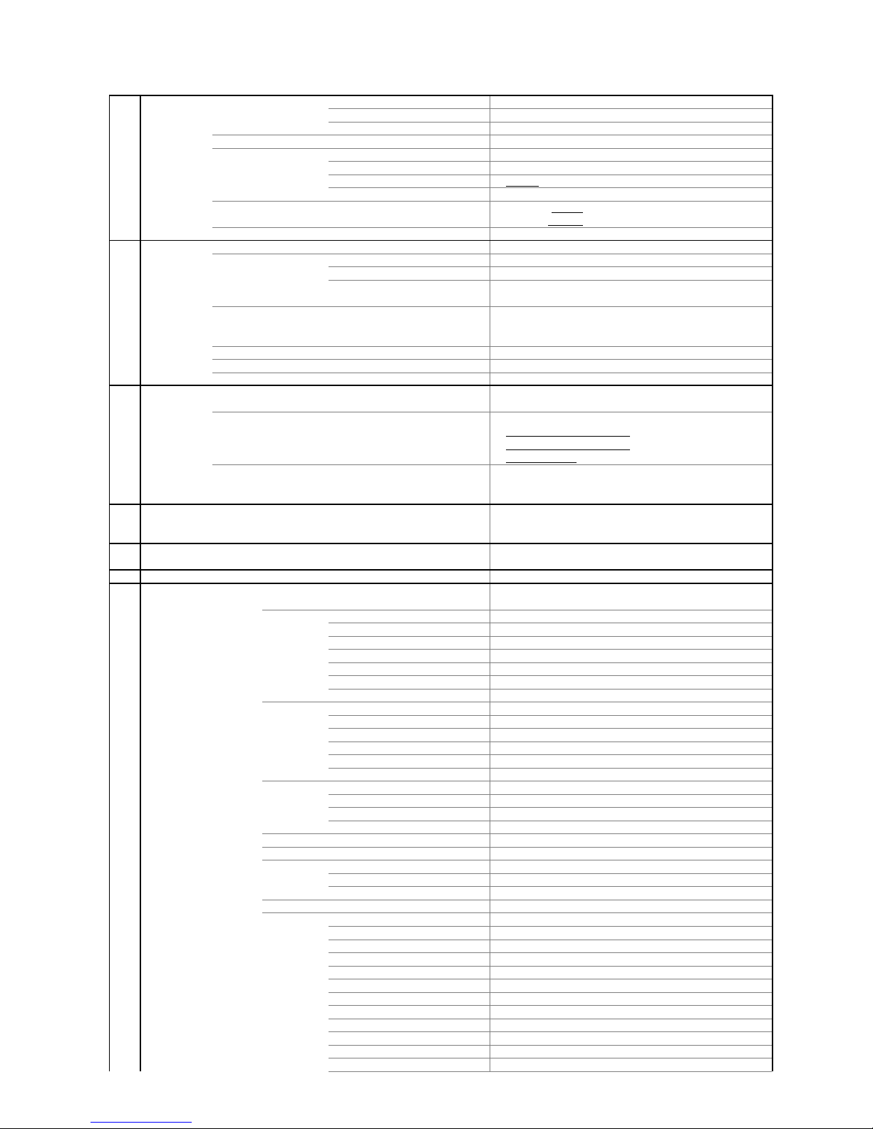
GENERAL SPECIFICATIONS
G-1 TV
CRT CRT Size / Visual Size 19 inch / 480mmV
System
CRT Type Normal
Magnetic Field BV/BH +0.45G/0.18G
Color System NTSC
Speaker 2Speaker
Position Ext
Size 3 Inch
Impedance 8 ohm
Sound Output MAX 0.5+0.5
W
10%(Typical) --
W
NTSC3.58+4.43 /PAL60Hz No
G-2 Tuning
Broadcasting System US System M
System
Tuner and System 1Tuner
Receive CH Destination USA(W/ CATV)
2 - 69, 4A, A-5 - A-1,
CH Coverage A - I, J - W, W+1 - W+84
Intermediate Picture(FP) 45.75MHz
Frequency Sound(FS) 41.25MHz
FP-FS 4.50MHz
Preset CH
No
StereoTV Sound (Ext Audio Input Only) Yes
Tuner Sound Muting Yes
G-3 Power
Power Source AC 120V AC 60Hz
DC
Power Consumption at AC
73 W at AC 120 V 60 Hz
Stand by (at AC) 3 W at AC 120 V 60 Hz
Per Year -- kWh/Year
Protector Power Fuse Yes
Safety Circuit Yes
IC Protector(Micro Fuse) No
G-4 Regulation
Safety UL / CSA
Radiation FCC / IC
X-Radiation DHHS / HWC
G-5 Temperature
Operation
+5oC ~ +40oC
Storage
-20oC ~ +60oC
G-6 Operating Humidity
Less than 80% RH
G-7 On Screen
Menu Yes
Display
Menu Type Disney Charecter
Picture Yes
Contrast Yes
Brightness Yes
Color Yes
Tint Yes
Sharpness Yes
Reset Yes
Audio No
Bass No
Treble No
Balance No
BBE On/Off No
Stable Sound On/Off No
CH Set Up Yes
TV/CATV Yes
Auto CH Memory Yes
Add/ Delete Yes
Language Yes
V-chip Yes
CH Label No
Favorite CH No
Color Stream DVD/DTV No
CAPTION Yes
Control Level Yes
Sound Yes
Brightness Yes
Contrast Yes
- Color Yes
Tint Yes
Sharpness Yes
Tuning No
Bass No
Treble No
Balance No
Back Light No
A3-1
GENERAL SPECIFICATIONS
Stereo,Audio Output,SAP No
Video Yes
Color Stream No
Channel(TV/Cable) Yes
CH Label No
Sleep Timer Yes
Sound Mute Yes
V-chip Rating Yes
G-8 OSD Language
English French Spanish
G-9 Clock and
Sleep Timer Max Time 120 Min
Timer
Step 10 Min
On/Off Timer Program(On Timer / Off Timer) No
Wake Up Timer No
Timer Back-up (at Power Off Mode) more than -- Min Sec
G-10 Remote
Unit RC-JK
Control
Glow in Dark Remocon No
Format NEC
Custom Code 86-05 h
Power Source Voltage(D.C) 3V
UM size x pcs UM-4 x 2 pcs
Total Keys 23 Keys
Keys Power Yes
1 Yes
2 Yes
3 Yes
4 Yes
5 Yes
6 Yes
7 Yes
8 Yes
9 Yes
0 Yes
100 No
CH Up Yes
CH Down Yes
Volume Up Yes
Volume Down Yes
TV/Caption/Text Yes
CH1/CH2 Yes
TV/Video(TV/AV) Yes
CH RTN/CH ENT(Quick View) Yes
Sleep Yes
RE Call(Call) Yes
Reset No
Menu Yes
Enter No
Mute Yes
Exit No
MTS(Audio Select) No
Set + No
Set - No
Multi Brand Keys CH Up(VCR) No
CH Down(VCR) No
Pause/Still No
TV/VCR(VCR) No
Code No
FF No
Rew No
Rec No
Play No
Stop No
TV No
VCR No
Cable No
G-11 Features
Auto Degauss Yes
Auto Shut Off Yes
Canal+ No
CATV Yes
Anti-theft No
Rental No
Memory(Last CH) Yes
Memory(Last Volume) Yes
V-Chip Yes
A3-2
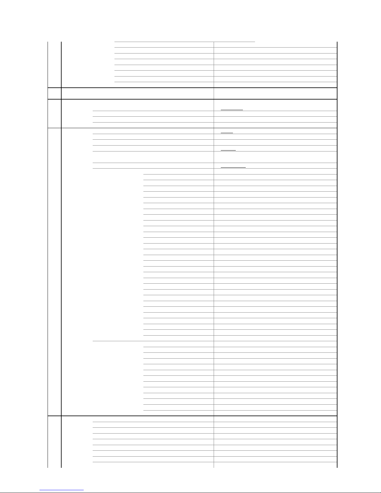
GENERAL SPECIFICATIONS
Type USA,ORION Type
BBE No
Auto Search No
CH Allocation No
StereoTV Sound (Ext Audio Input Only) Yes
Channel Lock No
Just Clock Function No
Game Position No
CH Label No
VM Circuit No
Full OSD No
Premiere No
Comb Filter No
Lines
Auto CH Memory Yes
Hotel Lock No
Closed Caption Yes
Stable Sound No
Energy Star No
Power On Memory Yes
Favorite CH No
G-12 Accessories
Owner's Manual Language English Spanish French
w/Guarantee Card
No
Remote Control Unit Yes
Rod Antenna
No
Poles
Terminal
Loop Antenna
No
Terminal -
U/V Mixer
No
DC Car Cord (Center+)
No
Guarantee Card Yes
Warning Sheet
No
Circuit Diagram
No
Antenna Change Plug
No
Service Facility List
No
Important Safeguard
No
Dew/AHC Caution Sheet
No
AC Plug Adapter
No
Quick Set-up Sheet
No
Battery
No
UM size x pcs
OEM Brand
No
AC Cord
No
AV Cord (2Pin-1Pin)
No
Registration Card
No
PTB Sheet
No
300 ohm to 75 ohm Antenna Adapter
No
Safety Strap Yes
Disney Leaflet
Yes
Mambo Mickey
No
Aladdin Coupon
No
G-13 Interface
Switch Front Power Yes
System Select No
Main Power SW No
Sub Power No
Channel Up Yes
Channel Down Yes
Volume Up Yes
Volume Down Yes
MENU Yes
TV/Video Yes
Rear AC/DC No
TV/CATV Selector No
Degauss No
Main Power SW No
Indicator Power No
Stand-by No
On Timer No
Terminals Front Video Input
RCA x 1
Audio Input
RCA x 2
Other Terminal
Head Phone
Rear Video Input(Rear1)
RCA x 1
Video Input(Rear2) No
A3-3
GENERAL SPECIFICATIONS
Audio Input(Rear1)
RCA x 2
Audio Input(Rear2) No
Video Output No
Audio Output No
Euro Scart No
Color Stream No
Diversity No
Ext Speaker
Yes
DC Jack 12V(Center +) No
VHF/UHF Antenna Input
F Type
AC Outlet No
G-14 Set Size
Approx. W x D x H (mm) 510.0 x 442.5 x 543
w/o Speaker,Legs Approx. W x D x H (mm) 510.0 x 442.5 x 488.5
G-15 Weight
Net (Approx.) 17.4kg
( 38.3lbs)
Net w/o Speaker,Legs Approx. 17.0 kg
( 37.4lbs )
Gross (Approx.) 21.3kg
( 46.9lbs)
G-16 Carton
Master Carton
No
Content ----
Sets
Material --
/--
Dimensions W x D x H(mm) -- x -- x --
Description of Origin
No
Gift Box Material Double / Full Color
Dimensions W x D x H(mm) 596 x 575 x 580
Description of Origin Yes
Drop Test
Natural Dropping At 1 Corner / 3 Edges / 6 Surfaces
Height (cm) 46
Container Stuffing 316
Sets/40' container
G-17 Cabinet Material
Cabinet Cabinet Front PS 94V0 DECABROM
Cabinet Rear PS 94V0 DECABROM
PCB Non-Halogen Demand
No
Eyelet Demand
No
G-18 Environment
Environmental standard requirement Green procurement of ORION
Pb-free Phase3(Phase3A)
A3-4
1. REMOVAL OF ANODE CAP
Read the following NOTED items before starting work.
After turning the power off there might still be a potential
voltage that is very dangerous. When removing the
Anode Cap, make sure to discharge the Anode Cap's
potential voltage.
Do not use pliers to loosen or tighten the Anode Cap
terminal, this may cause the spring to be damaged.
REMOVAL
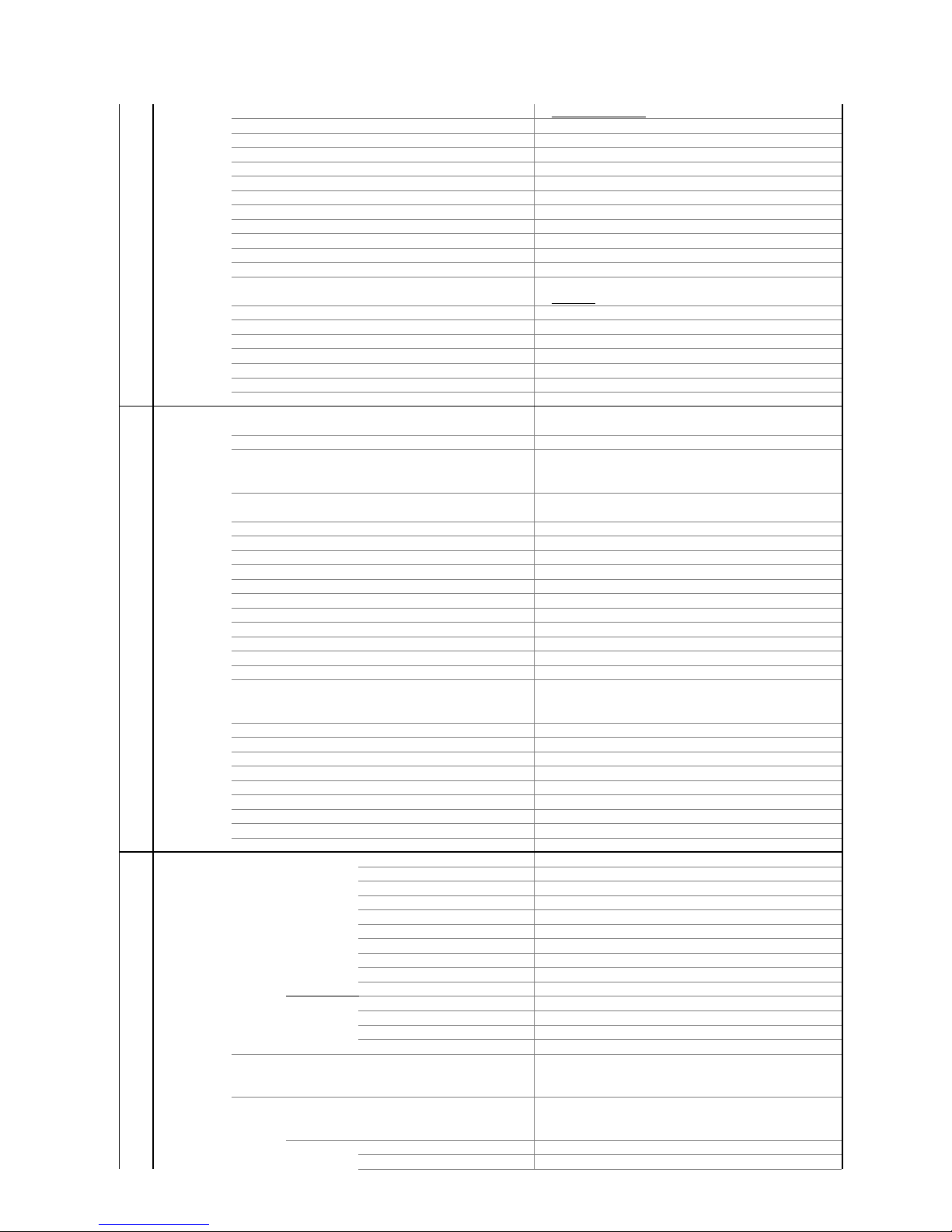
1. Follow the steps as follows to discharge the Anode Cap.
(Refer to Fig. 1-1.)
Connect one end of an Alligator Clip to the metal part of
a flat-blade screwdriver and the other end to ground.
While holding the plastic part of the insulated screwdriver,
touch the support of the Anode with the tip of the
screwdriver.
A cracking noise will be heard as the voltage is discharged.
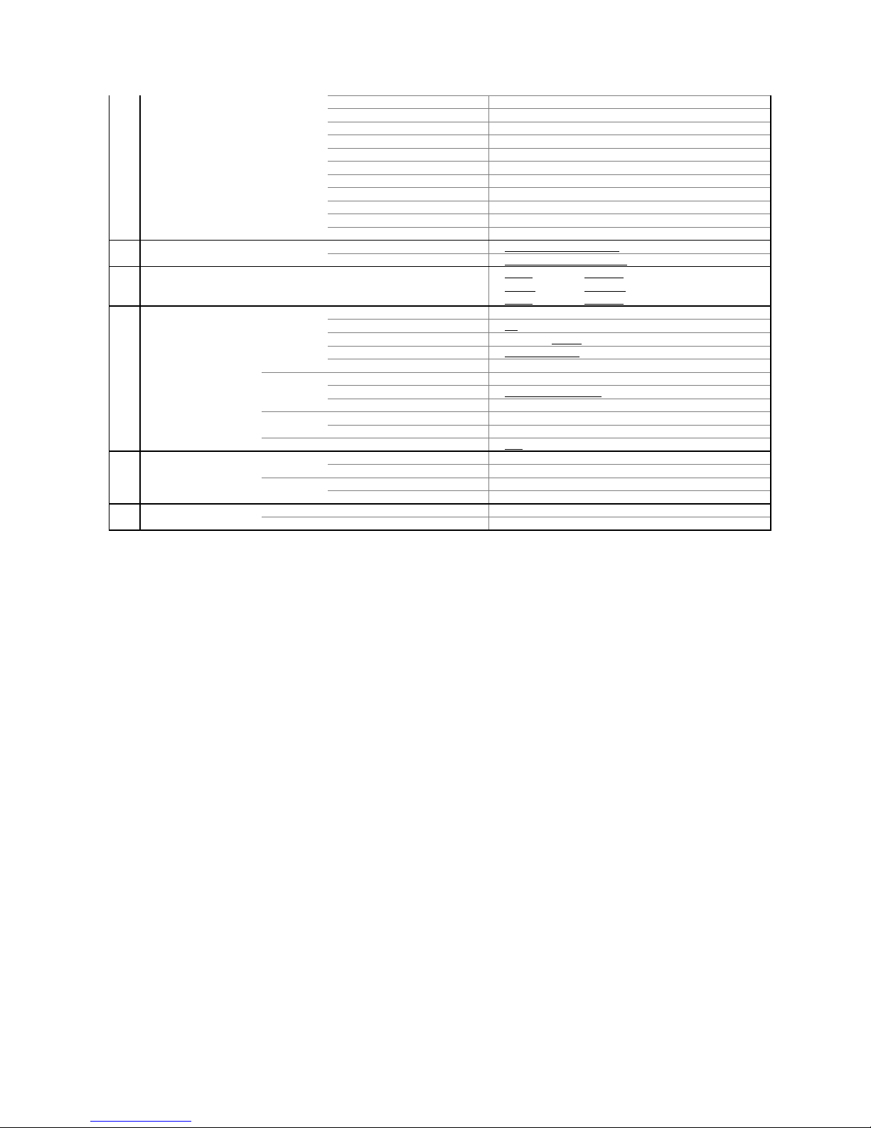
Flip up the sides of the Rubber Cap in the direction of the
arrow and remove one side of the support.
(Refer to Fig. 1-2.)
2.
GND on the CRT
Screwdriver
Alligator Clip
Support
CRT
GND on the CRT
Rubber Cap
CRT
Support
Fig. 1-2
3. After one side is removed, pull in the opposite direction to
remove the other.
NOTE
Take care not to damage the Rubber Cap.
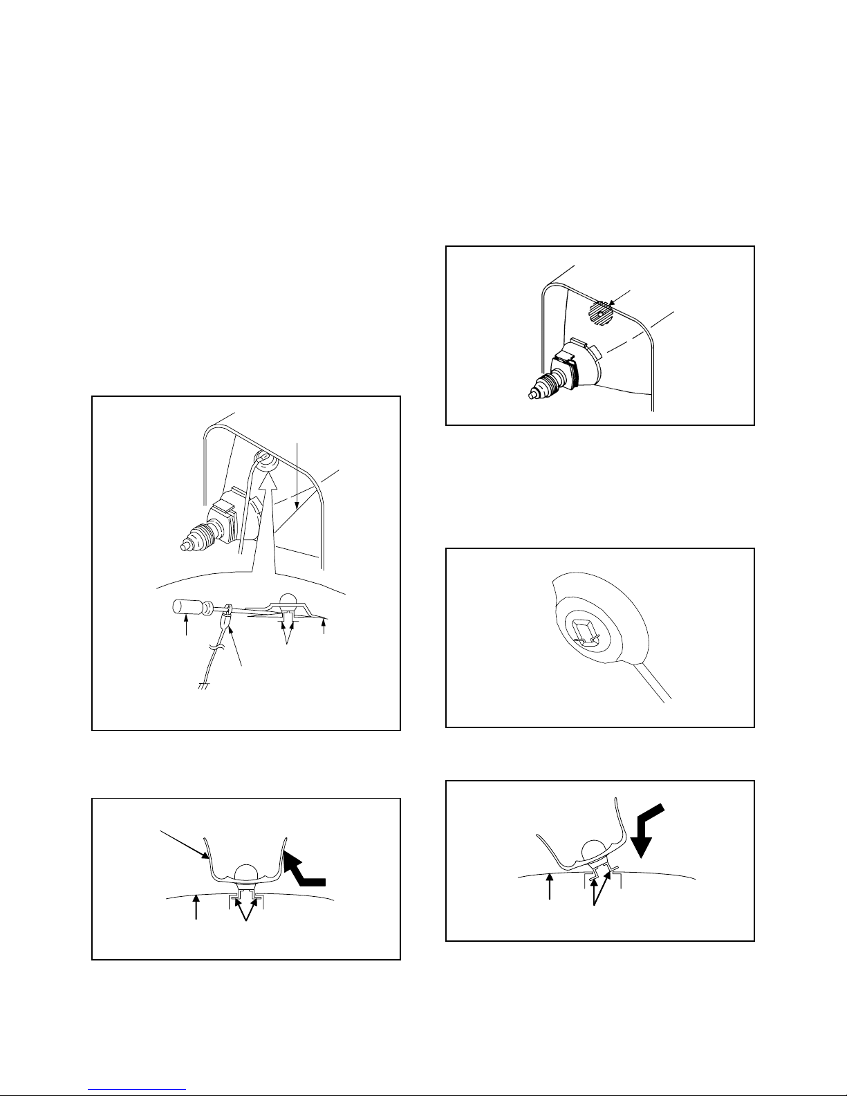
INSTALLATION
1. Clean the spot where the cap was located with a small
amount of alcohol. (Refer to Fig. 1-3.)
Location of Anode Cap
NOTE
Confirm that there is no dirt, dust, etc. at the spot where
the cap was located.
2.3.Arrange the wire of the Anode Cap and make sure the
wire is not twisted.
Turn over the Rubber Cap. (Refer to Fig. 1-4.)
4. Insert one end of the Anode Support into the anode button,
then the other as shown in Fig. 1-5.
5.6.Confirm that the Support is securely connected.
Put on the Rubber Cap without moving any parts.
CRT
Support
DISASSEMBLY INSTRUCTIONS
Fig. 1-3
Fig. 1-4
Fig. 1-5
*
*
Fig. 1-1
B1-1
B2-1
Masking Tape
(Cotton Tape)
DISASSEMBLY INSTRUCTIONS
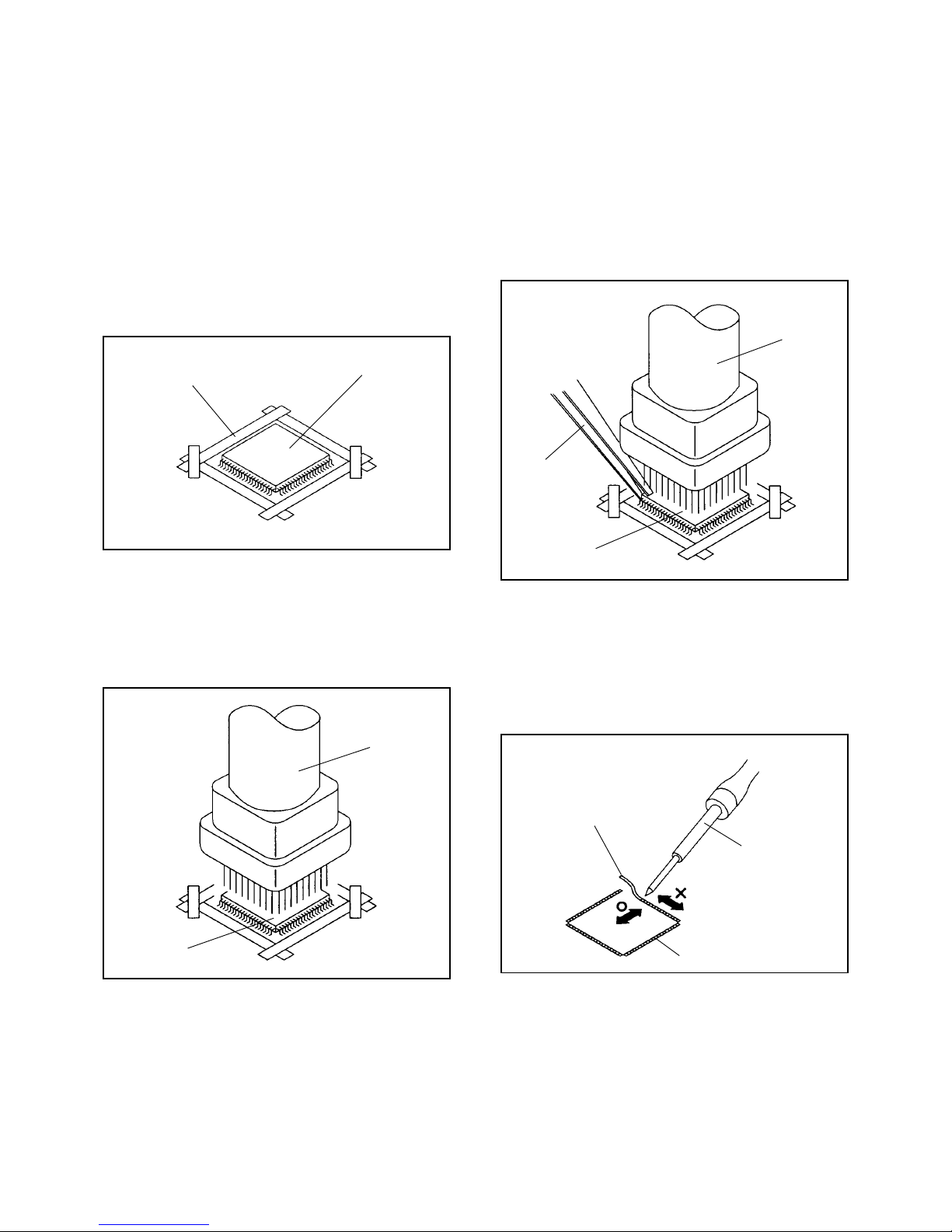
2.
REMOVAL
IC
Put Masking Tape (cotton tape) around the Flat Package
IC to protect other parts from any damage.
(Refer to Fig. 2-1.)
1.
Fig. 2-1
NOTE
REMOVAL AND INSTALLATION OF
FLAT PACKAGE IC
Some ICs on the PCB are affixed with glue, so be
careful not to break or damage the foil of each IC
leads or solder lands under the IC when removing it.
NOTE
Masking is carried out on all the parts located within
10 mm distance from IC leads.
Blower type IC
desoldering machine
IC
Heat the IC leads using a blower type IC desoldering
machine. (Refer to Fig. 2-2.)
2.
Fig. 2-2
NOTE
Do not rotate or move the IC back and forth until IC
can move back and forth easily after desoldering the
leads completely.
When IC starts moving back and forth easily after
desoldering completely, pickup the corner of the IC using
a tweezers and remove the IC by moving with the IC
desoldering machine. (Refer to Fig. 2-3.)
3.
Blower type IC
desoldering
machine
IC
Fig. 2-3
Tweezers
Peel off the Masking Tape.4.
Absorb the solder left on the pattern using the Braided
Shield Wire. (Refer to Fig. 2-4.)
5.
NOTE
Do not move the Braided Shield Wire in the vertical
direction towards the IC pattern.
Braided Shield Wire
Soldering Iron
Fig. 2-4
IC pattern