

Page 1
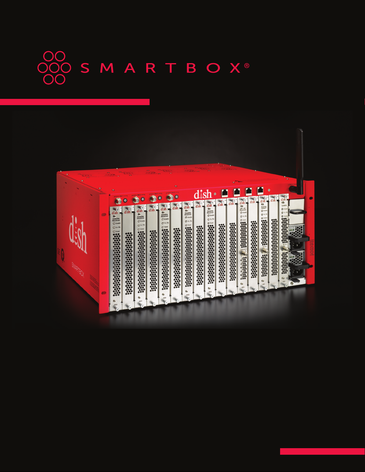
USER MANUAL
VERSION 3.1
APRIL 2018
1
Page 2

Manufactured under license from Dolby Laboratories.
Dolby and the double-D symbol are trademarks of Dolby Laboratories.
2
Page 3

TABLE OF CONTENTS
Important Safety Information ....................................................................................................5
CHAPTER 1 Introduction to SMARTBOX ........................................................................................8
Site Requirements ..........................................................................................................8
Installation Overview ....................................................................................................... 9
CHAPTER 2 Assemble Chassis, Power Supplies, and Power Inserters .....................................................10
Install Chassis and Power Supplies ....................................................................................... 10
Mount Power Inserter and Connect Input/Output Cables to Power Inserter ..........................................11
DISH 4-Port High-Capacity Power Inserter ..............................................................................11
CHAPTER 3 Install Blades ......................................................................................................12
Plan Distribution of Blades ................................................................................................12
Inspect Blades ..............................................................................................................13
Install the Blades and Filler Plates ........................................................................................13
CHAPTER 4 Update Software .................................................................................................. 14
Configure Computer Network Settings ..................................................................................14
Establish Communication with SMARTBOX ..............................................................................16
Connect Cables to Connectors and Install Cellular Antenna ...........................................................16
Login to SMARTBOX ....................................................................................................... 17
Admin Tab ..................................................................................................................18
Chassis Tab ................................................................................................................. 18
Enable Satellite Inputs .....................................................................................................19
Verify Tuners Lock .........................................................................................................20
Download Software from Satellite ........................................................................................21
Update Settings for Automatic Update ...................................................................................21
Download Software from SFTP ...........................................................................................21
Manually Update Software ................................................................................................22
CHAPTER 5 Feature-Enabling Codes .........................................................................................23
CHAPTER 6 Authorize SMARTBOX ............................................................................................ 24
Authorization – 100% ......................................................................................................25
Authorization – Less Than 100% ..........................................................................................26
Authorization Page .........................................................................................................27
CHAPTER 7 Scan for Spot Beams and Satellite Services ....................................................................28
CHAPTER 8 Specify Data Port—Content/Control Interface ..................................................................29
BULK OPERATIONAL MODE, CH 912
CHAPTER 9 ATSC Installation ..................................................................................................30
ATSC Input Signal Characteristics ........................................................................................30
ATSC GUI Interface ........................................................................................................33
CHAPTER 10 Set Up CAS Server ..............................................................................................34
CHAPTER 11 Map Services .....................................................................................................35
Configuration File ..........................................................................................................36
Configure Services ......................................................................................................... 36
Encrypted QAM Output ....................................................................................................37
HD Over Coax Output .....................................................................................................37
NTSC Output ...............................................................................................................37
Max Services Per QAM Channel ..........................................................................................38
Encrypted IP Stream Output ..............................................................................................38
Quick Add .................................................................................................................. 39
IP Input (Welcome Channel) ...............................................................................................39
General Requirements .....................................................................................................39
IP Packet Details ...........................................................................................................39
Transport Stream Format ..................................................................................................40
PIDs .........................................................................................................................40
Timing/PCRs ................................................................................................................40
Continuous Video and Audio ............................................................................................. 40
Adding the IP Input Service(s) ............................................................................................. 41
Add Monroe R189 EAS (Emergency Alert System) ......................................................................42
Part-Time HD Alternate Display (RSN) ..................................................................................... 42
3
Page 4

CHAPTER 12 Set Up a Program Guide ......................................................................................... 43
Configure Program Guide Output Options ...............................................................................43
Configure Update Time for the Guide Channel ..........................................................................44
Adding External Services to the Program Guide ........................................................................45
CHAPTER 13 Evolve Configuration ............................................................................................46
Set Up the DVB-SI Service ................................................................................................47
Adding Additional Files ....................................................................................................47
Replacing Existing Files ...................................................................................................49
Set Up ATSC for EVOLVE ..................................................................................................49
Set Zones for Services ..................................................................................................... 51
NOTE-Nuances to Feeding Video to Non-EVOLVE Devices ............................................................52
DISH QAM OPERATIONAL MODE, CH 14
CHAPTER 14 DISH QAM ........................................................................................................ 53
Set Up DISH QAM ..........................................................................................................53
Validate DISH QAM Status ................................................................................................55
CHAPTER 15 Manual Factory Default .......................................................................................... 56
Factory Default Without Access to User Interface ....................................................................... 56
CHAPTER 16 Soak Test and Prepare to Ship .................................................................................. 57
Soak Test ...................................................................................................................57
Prepare to Ship ............................................................................................................. 57
CHAPTER 17 Install on Customer Site ......................................................................................... 58
CHAPTER 18 Status, Warnings, and Faults ....................................................................................59
CHAPTER 19 Diagnostic Information ..........................................................................................60
ATSC Receiver Blades .....................................................................................................60
Satellite Receiver Blades ..................................................................................................60
CHAPTER 20 LED Information .................................................................................................61
LED Definitions for Satellite Feeds ........................................................................................ 61
LED Definitions for Blades .................................................................................................61
LED Definitions for Cellular Antennas ....................................................................................61
CHAPTER 21 NTSC Channel - Frequency .....................................................................................62
CHAPTER 22 Hardware Components .........................................................................................63
16-Slot Chassis .............................................................................................................63
8-Channel Satellite Receiver Blade .......................................................................................63
8-Channel Satellite Receiver Blade with Transcoder Module ..........................................................63
8-Channel ATSC Receiver Blade ..........................................................................................63
QAM 16 Blade ..............................................................................................................63
QAM 48 Blade .............................................................................................................. 63
QAM 96 Blade ..............................................................................................................63
24-Channel Analog NTSC TV Blade ...................................................................................... 63
Power Supply ............................................................................................................... 63
Chassis Spare Fan Assembly .............................................................................................63
Single Blade Filler Plates ..................................................................................................63
Power Supply Filler Plate ..................................................................................................63
CHAPTER 23 Technical Specifications ........................................................................................64
Power Consumption .......................................................................................................64
Chassis Assembly Specifications .........................................................................................65
Power Supply Module ..................................................................................................... 67
LED Status .................................................................................................................. 67
Satellite Receiver Blade ...................................................................................................68
Satellite Receiver Blade with Transcoder Module .......................................................................68
ATSC Receiver Blade ......................................................................................................68
QAM 16 Blade ..............................................................................................................69
QAM 48 Blade .............................................................................................................. 69
QAM 96 Blade ..............................................................................................................70
NTSC 24 Blade .............................................................................................................70
Tolerances and Ranges .................................................................................................... 71
CHAPTER 24 Warranty Information and Return Authorization ..............................................................72
CHAPTER 25 Trademark Acknowledgements ...............................................................................72
CHAPTER 26 Technical Support and Authorization Assistance ............................................................72
REGULATORY COMPLIANCE ..................................................................................................73
4
Page 5
IMPORTANT SAFETY INFORMATION
To ensure proper installation and operation, read this guide before proceeding with the installation. If you have
any questions or comments, please contact your dealer.
The lightning flash with arrowhead symbol, within an equilateral triangle, is intended to
alert the user to the presence of uninsulated “dangerous voltage” within the product’s
enclosure that may be of sucient magnitude to constitute a risk of electric shock to
persons.
The exclamation point within an equilateral triangle is intended to alert the user to the
presence of important operating instructions accompanying the appliance.
WARNING:
CAUTION:
Read Instructions: All safety and operating instructions
should be read before the appliance
is operated.
Retain Instructions: The safety and operating
instructions should be retained for future reference.
• TO REDUCE THE RISK OF FIRE OR ELECTRIC SHOCK, DO NOT EXPOSE THIS
APPLIANCE TO RAIN OR MOISTURE.
• DO NOT OPEN THE CABINET.
• REFER SERVICING TO QUALIFIED PERSONNEL ONLY.
TO PREVENT ELECTRIC SHOCK, DO NOT USE THE POLARIZED PLUG WITH AN
EXTENSION CORD RECEPTACLE OR OTHER OUTLET UNLESS ALL THE BLADES CAN BE
FULLY INSERTED TO PREVENT BLADE EXPOSURE.
Reliable Earthing: Reliable earthing of rack-mounted
equipment should be maintained. Particular attention
should be given to supply connections other than
direct connections to the branch circuit (e.g., use of
power strips).
Power Sources: This product should be operated
only from the type of power source indicated on the
marking label. If you are not sure of the type of power
supplied to your location, consult your dealer or local
power company.
Heed Warnings: All warnings on the appliance should
be adhered to.
Power-Cord Protection: Power-supply cords should
be routed so they are not likely to be walked on or
pinched by items placed on or against them. Pay
particular attention to cords and plugs, convenience
receptacles and the point where they exit from
the appliance.
5
Page 6
Follow Instructions: All operating and user instructions
should be followed.
Lightning: For added protection for this product
during a lightning storm or when it is left unattended
or unused for long periods of time, the unit should be
disconnected from the power source.
Cleaning: Unplug this appliance from the wall outlet
before cleaning. Use a damp cloth for cleaning. Do not
use liquid or aerosol cleaners.
Do Not Use Attachments: Use of attachments not
recommended by the manufacturer may cause
hazards.
Water and Moisture: Do not use this product near
water (e.g., near a bathtub, washbowl, kitchen sink,
laundry tub, in a wet basement, or near a
swimming pool).
Accessories: Do not place this product on an unstable
cart, stand, tripod, bracket or table. The product may
fall, causing serious injury to a child or adult and
serious damage to the appliance.
Power Lines: An outside antenna system should not be
located in the vicinity of overhead power lines or other
electric light or power circuits where it can fall into
such power lines or circuits. When installing an outside
antenna system, extreme care should be taken to keep
from touching power lines or circuits—contact with
them may be fatal.
Object and Liquid Entry: Never push objects of any
kind through openings into this product as they may
touch dangerous voltage points or short-out parts that
could result in a fire or electric shock. Never spill liquid
of any kind on the product.
Servicing: Do not attempt to service this product
yourself, as opening or removing covers may expose
you to dangerous voltage or other hazards. Refer all
servicing to qualified service personnel.
Damage Requiring Service: Unplug this product from
the wall outlet and refer servicing to qualified service
personnel under the following conditions:
a) When the power-supply cord or plug is damaged.
b) If liquid has been spilled or objects have fallen into
the product.
c) If the product has been exposed to rain or water.
d) If the product does not operate normally by
following the operating instructions. Adjust only
those controls that are covered by the operating
instructions. An improper adjustment may result in
damage and will often require extensive work by
a qualified technician to restore the product to its
normal operation.
e) If the product has been dropped or the cabinet has
been damaged.
f) When the product exhibits a distinct change in
performance—this indicates a need for service.
Elevated Operating Ambient Temperature: If installed
in a closed or multi-unit rack assembly, the operating
ambient temperature of the rack environment may be
greater than room ambient. Therefore, consideration
should be given to installing the equipment in an
environment compatible with the maximum ambient
temperature of 50°C.
Reduced Air Flow: Installation of the equipment in
a rack should be such that the amount of air flow
required for safe operation of the equipment is
not compromised.
6
Replacement Parts: When replacement parts are
required, be sure the service technician has used
replacement parts specified by the manufacturer or
that have the same characteristics as the original parts.
Unauthorized substitutes may result in fire, electric
shock or other hazards.
Safety Check: Upon completion of any service or
repairs to this product, ask the service technician to
perform safety checks to determine that the product
is in proper operating conditions.
Page 7
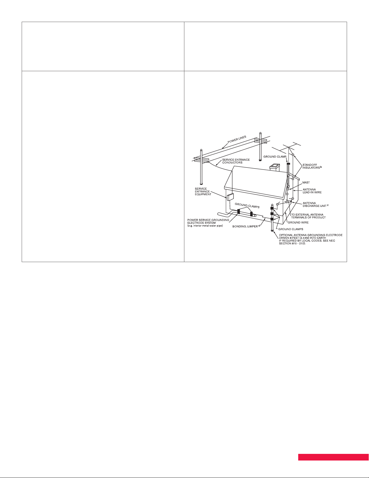
Mechanical Loading: SMARTBOX is designed to
EXAMPLE OF ANTENNA GROUNDING ACCORDING TO
NATIONAL ELECTRICAL CODE INSTRUCTIONS CONTAINED
IN ARTICLE 810 - “RADIO AND TELEVSION EQUIPMENT”
be rack-mounted in a standard EIA 19-inch-width
telecommunications rack. Mounting of the equipment
in the rack should be such that a hazardous condition
is not achieved due to uneven mechanical loading.
Outdoor Antenna Grounding: Before attempting
to install this product, be sure the antenna or cable
system is grounded so as to provide some protection
against voltage surges and built-up static charges.
a) Use No.10 AWG (5.3mm) copper, No.8 AWG (8.4mm)
aluminum, No.7 AWG (10mm) copper-clad steel or
bronze wire or larger, as ground wire.
b) Secure antenna lead-in and ground wires to house
with stand-o insulators spaced from 4 feet (1.22m)
to 6 feet (1.83m) apart.
c) Mount antenna discharge unit as close as possible to
where lead-in enters the building.
d) A driven rod may be used as the grounding
electrode where other types of electrode systems
do not exist. Refer to the National Electrical Code,
ANSI/NFPA 70-1984 for information.
Circuit Overloading: Consideration should be given to
the connection of the equipment to the supply circuit
and the eect that overloading of the circuits might
have on over-current protection and supply wiring.
Appropriate consideration of equipment nameplate
ratings should be used when addressing this concern.
Grounding Example from
National Electrical Code
e) Use jumper wire not smaller than No.6 AWG
(13.3mm) copper or equivalent, when a separate
antenna grounding electrode is used.
7
Page 8

CHAPTER 1 INTRODUCTION TO SMARTBOX®
Thank you for purchasing a DISH SMARTBOX. SMARTBOX is a revolutionary centralized video distribution system
that can use both bulk and Dish QAM operational modes. SMARTBOX is much more than a commercial satellite
receiver—it is a highly integrated video distribution platform that operates in a 7/24/365 environment. Furthermore,
SMARTBOX is highly flexible and provides multiple operating modes that can be enabled simultaneously.
There are three functional concepts that are important to understand about SMARTBOX:
1. Signal Reception—SMARTBOX uses a single common set of assets to receive DISH satellite signals. The
satellite receiver blades then output TV channels or transponders to the backplane in the chassis for
distribution by one or more signal output blades. No output blade is required for IP distribution.
2. Signal Output—Multiple options for video output are available. These various output blades can be
configured in any combination because of the SMARTBOX architecture.
3. Operational Modes—All modes of operation in SMARTBOX are enabled via DISH feature-enabling codes.
Unlike other third-party devices that have been historically used with DISH receivers, the outputs for
SMARTBOX must be authorized by DISH or they will not function.
Site Requirements
All sites must provide the following:
1. One or more installed and “peaked” satellite dishes with low-noise-block-feeds (LNBFs).
Supported satellite orbitals:
• East Arc: 61.5, 72.7 and 77 degrees
• West Arc: 110, 119 and 129 degrees
• International: 118.7 degrees
NOTES:
• SMARTBOX allows the utilization of either Eastern or Western Arc orbitals with the optional addition of
the International orbital. Mixing Eastern and Western Arc orbitals is not allowed.
• Satellite at 121 degrees is not supported.
2. DISH 4-port high-capacity power inserter/surge protector (DN005050) and cables.
3. Nine inches of clearance above the SMARTBOX chassis for cooling airflow exhaust.
4. External terrestrial antennas installed and cabled to receive local channels for installations needing o-air
(ATSC) sources.
5. Internet connectivity via Ethernet cable and/or cellular modem connectivity via antenna mounted
on SMARTBOX.
6. 120V AC power for SMARTBOX power supplies and power inserters.
7. Ambient air temperature maintained around SMARTBOX between 0° and 50°C (32°–122°F) for
system cooling.
8. Non-condensing relative humidity around SMARTBOX between 5% to 95%.
9. Site plan/schema for mapping services and/or transponders to plant carrier frequencies.
8
Page 9

Installation Overview
The following is an overview of the process of assembling, testing and delivering SMARTBOX to a customer site.
Subsequent chapters contain detailed step-by-step instructions. Follow the information flow of the chapters to
ensure a successful setup of SMARTBOX hardware and software.
• Assemble Power Components — Connect cables, power supplies and power.
• Install Blades — Plan distribution of blades and install.
• Configure Computer Network Settings — Configure computer settings to access SMARTBOX
User Interface.
• Login to SMARTBOX — Login to the SMARTBOX User Interface to begin configuring your system.
• Enable Satellites — Enable satellites and verify that tuners lock properly.
• Update Software — Download software, connect to network, update software and reboot.
• Authorize SMARTBOX — Authorize SMARTBOX with DISH and resolve any authorization problems.
• Scan for Satellite Services — Scan for satellite services to populate Services page based on visible
orbitals/transponders and authorized programming.
• Set Up Data Port(s) — Specify Content/Control Interface for data ports.
• Set Up CAS Server — Enter address and details for encryption if Verimatrix or Lynk is employed.
• Map Services (Bulk) — Configure services for output (QAM, NTSC, IP Stream) and set up the
Program Guide.
• DISH QAM (Digital Upgrade) — Configure transponders and frequency range.
• Export Configuration File — Store this file, save your mapped services for this configuration.
• Perform Soak Test — Run SMARTBOX 24 to 48 hours. Perform a functional test at the end of the soak to
ensure all components are working.
• Prepare to Ship — Shut SMARTBOX down, remove the power supplies and ship the unit to the
customer site.
• Install on Customer Site — Connect SMARTBOX to satellite feeds, power sources and Internet connection;
refresh satellites, scan for authorized services and set up Welcome Channel(s) and the
Program Guide.
NOTE: To ensure the latest software download, set up and test SMARTBOX just before it is due to be set up on
the customer site.
9
Page 10
CHAPTER 2 ASSEMBLE CHASSIS, POWER SUPPLIES,
AND POWER INSERTERS
SMARTBOX uses semiconductors that can be damaged by electrostatic discharge (ESD). When handling
SMARTBOX components, care must be taken to prevent damage. Damage due to improper handling is not
covered by warranty.
WARNING: The following precautions must be taken whenever handling bare circuitry —this includes removing
and/or inserting blades into the chassis. DO NOT OPEN the protective conductive packaging until you read the
following instructions and are at an antistatic work station.
• Use a conductive wrist strap attached to a stable earth ground.
• Use an antistatic mat to cover your work surface.
• Always discharge yourself by touching a grounded bare metal surface or
antistatic mat before picking up an ESD-sensitive electronic component.
• Keep the work area clear of non-ESD-safe items.
Install Chassis and Power Supplies
1. Remove the chassis, power supplies, blades and filler plates from the shipping boxes. Save the boxes and
packing material for future use.
2. Install the chassis in a 19-inch rack or a wall mount or position it on a desk or on top of a table. SMARTBOX is
designed so that all connections are on the front of the unit. The path of the air flow is through the front of
the unit and out the top of the unit.
CAUTION: The chassis requires at least 9 inches of clearance above the chassis fans to ensure adequate
airflow. DO NOT block the top or front of the chassis. Blank filler plates are needed for unused slots. This
ensures proper airflow through the chassis, which prevents overheating.
CAUTION: Ambient air temperature must be kept between 0° and 50°C (32°–122°F) to provide adequate
cooling for the system.
3. Plug the power supplies into the chassis.
WARNING: Ensure the chassis is connected to an earth ground; use the ground screw
next to the ground symbol (
at the beginning of this manual for specific information related to proper grounding.
) on the chassis. Refer to “Important Safety Instructions”
10
Page 11
Mount Power Inserter and Connect Input/Output Cables to Power Inserter
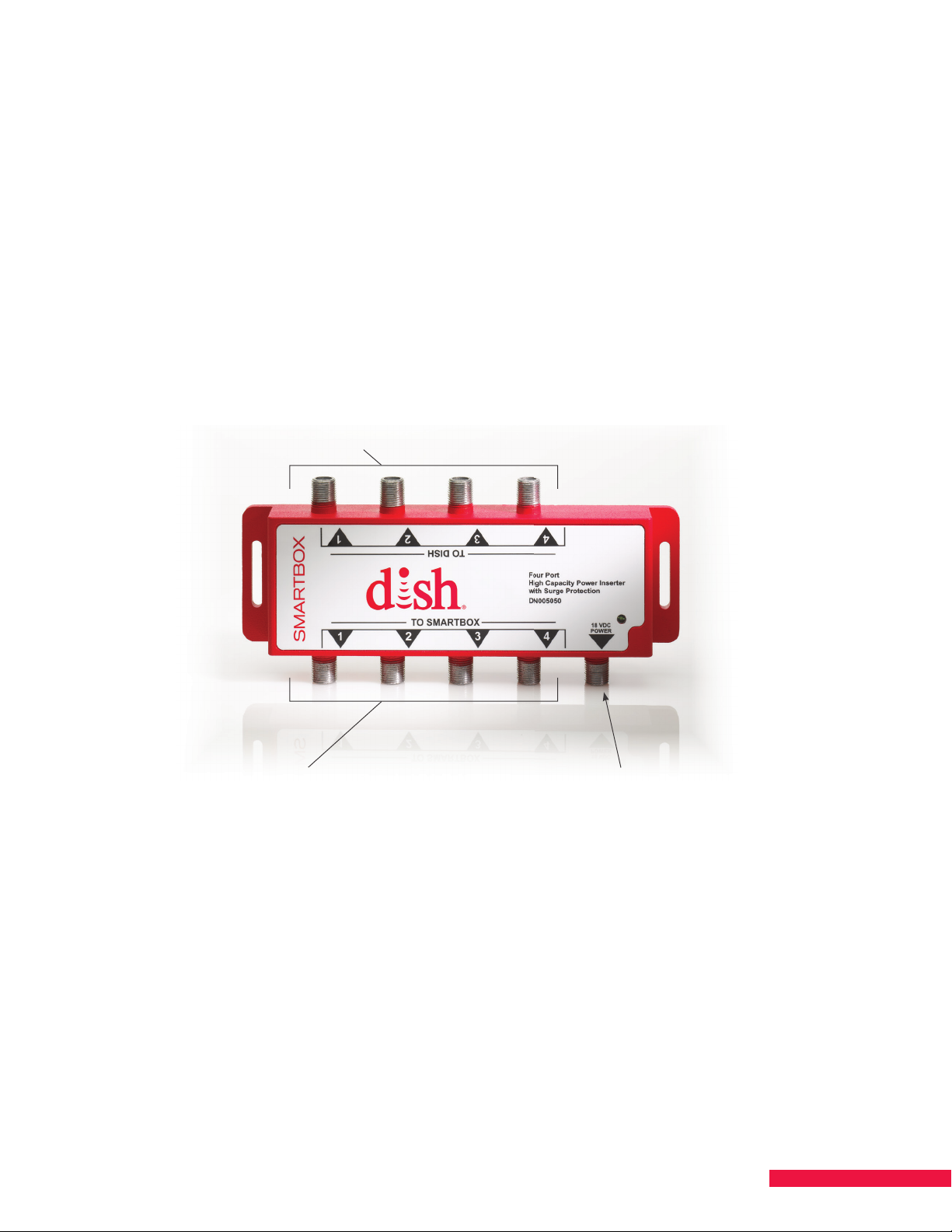
Connect LNBFs from satellites to “TO DISH” ports 1–4
Connect “TO SMARTBOX” ports 1–4 to
Sat 1, Sat 2, Sat 3, and Sat 4 connectors on front of SMARTBOX
Connect power adapter
to 18 VDC connector
An external power source and in-line surge protector(s) must be installed on the coax line(s) between SMARTBOX
and the satellite’s LNBF(s). The current recommended solution is the DISH 4-port high-capacity power inserter
with built-in surge protection (DN005050). This is only for situations where the LNBF is within 100 feet of
SMARTBOX.
CAUTION: For cable runs of greater than 100 feet, in-line amplifiers may be required.
DISH 4-Port High-Capacity Power Inserter
1. Securely mount a DISH 4-port high-capacity power inserter/surge protector to an appropriate
wall or surface.
2. Connect cables from the LNBFs to ports 1, 2, 3, 4 (as needed); these are marked TO DISH on the power
inserter (See Figure 1.).
Figure 1. DISH 4-Port High-Capacity Power Inserter with Surge Protection
3. Connect corresponding ports 1, 2, 3, 4 marked TO SMARTBOX on the power inserter to the Sat 1, 2, 3, 4
connectors on the front of SMARTBOX (See Figure 1.).
4. Connect the supplied AC adapter to the 18V DC power port on the power inserter.
5. Plug the AC adapter into a power source.
NOTE: If you have open ports, you can use the power inserter to power an OTA antenna’s amplifier.
11
Page 12
CHAPTER 3 INSTALL BLADES
5 Fans
4 LNBF
Ports/Sat
1-4
4 Ethernet/Data
Ports
Cellular
Modem
Antenna
Power
Supplies
Ground
Use slots 13-16 for
High Bandwidth blades that do
not need to access the RF backplane
or blank fi ller plates
Use left slots 1-12 for
Low Bandwidth and satellite
receiver blades or blank filler plates
Plan Distribution of Blades
Plan the distribution of the blades for the SMARTBOX chassis. Blades should be distributed as evenly as possible
across the slots. Blank filler plates are needed for unused slots. This ensures proper airflow through the chassis,
which prevents overheating.
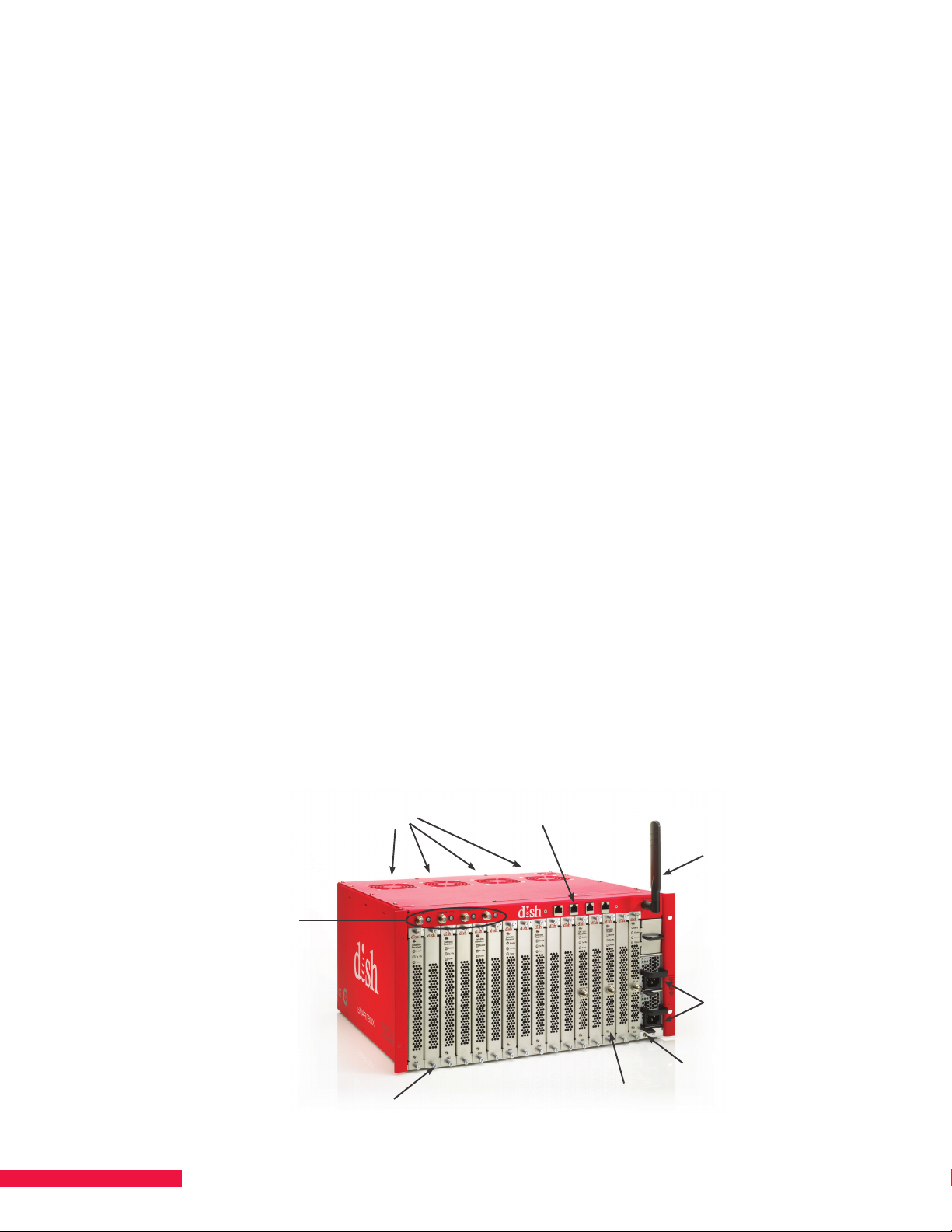
Arrange the blades as follows (See Figure 2.):
• Slots 1-12 are designed for Low Bandwidth blades and provide a connection to the RF backplane and digital
backplane. (Low bandwidth = 2 Gigabit connection)
– The Satellite Receiver Blade(s) must be placed in slots 1-12 to have the required connection to the
RF backplane.
– QAM 16 blades, NTSC blades and ATSC blades are Low Bandwidth blades and can be placed
into any slot.
• Slots 13-16 are designed for High Bandwidth blades and provide a higher bit rate connection to the digital
backplane. (High Bandwidth = 5 Gigabit connection)
– QAM 48 blades and QAM 96 blades are High Bandwidth blades and must be placed in these slots to
perform correctly.
NOTES:
• Every SMARTBOX must have at least one satellite receiver blade to operate.
• Installations requiring transcoding must have only satellite receiver blades with transcoder modules,
otherwise
the system will perform intermittently.
• A scrolling Program Guide is always an available service in Native (MPEG-4) format digitally and via NTSC
output in Bulk Distribution environments; it requires two satellite receiver blades, proper output blades, and
output authorizations to operate.
• Blades and power supplies are hot-swappable. To swap a power supply, first you must remove the power
cord. After swapping a satellite receiver blade, a software update, .csv download/upload to Salesforce.com,
and an authorization hit may be needed.
• If a part is missing, contact DISH or your distributor for replacement.
Figure 2. SMARTBOX Components
12
Page 13
Inspect Blades
Inspect each blade prior to installation:
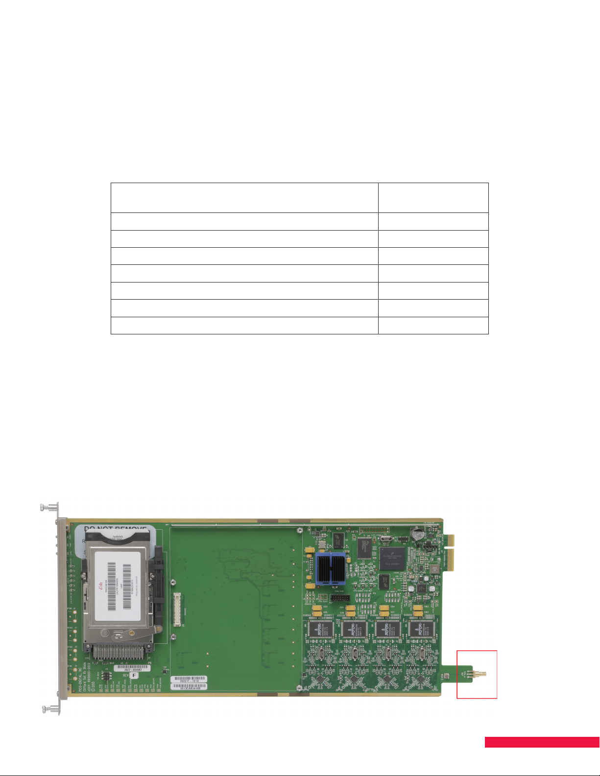
1. Verify that each satellite receiver blade has an RF connector (See Figure 3.) to connect the blade to
the backplane.
2. Verify that each satellite receiver blade has either two ProCAM 1.0s or one ProCAM 2.0. ProCAM 1.0s each
have a visible SmartCard while ProCAM 2.0s have embedded chips. Inspect to confirm that all ProCAMs
have been fully inserted into their cradle and the SmartCards have been fully inserted in the ProCAMs (only
when using ProCAM 1.0s).
3. Verify that heat sinks are in place on all blades and transcoder modules.
Component
Satellite Receiver Blades 1
Satellite Receiver Blades with Transcoder Modules 6
ATSC Receiver Blades 7
QAM 16 Blades 2
QAM 48 Blades 4
QAM 96 Blades 6
NTSC Blades 7
Number of Heat
Sinks
Install the Blades and Filler Plates
1. Install satellite receiver blades according to the distribution plan.
a) Slide the blade into the appropriate slot; ensure the satellite receiver blade is correctly installed.
b) Finger-tighten the screw on front of the blade to secure in chassis.
2. Install the remaining blades (QAM, ATSC, NTSC) according to plan; finger-tighten the front screws to secure
them to the chassis.
3. Install blank filler plates in empty slots; finger-tighten screws to secure them to the chassis.
Figure 3. RF Bullet Connector
13
Page 14
CHAPTER 4 UPDATE SOFTWARE
Configure Computer Network Settings
Network settings must be modified to enable communication between your computer and SMARTBOX.
Depending on the version of Windows™ on your network, the path to configure the connection may vary slightly.
Configuring an IP address is usually initiated through the Windows’ Control Panel and the Network option.
1. Open the Control Panel, then the Network option.
2. Double-click Local Area Connection. The Local Area Connection Properties window opens.
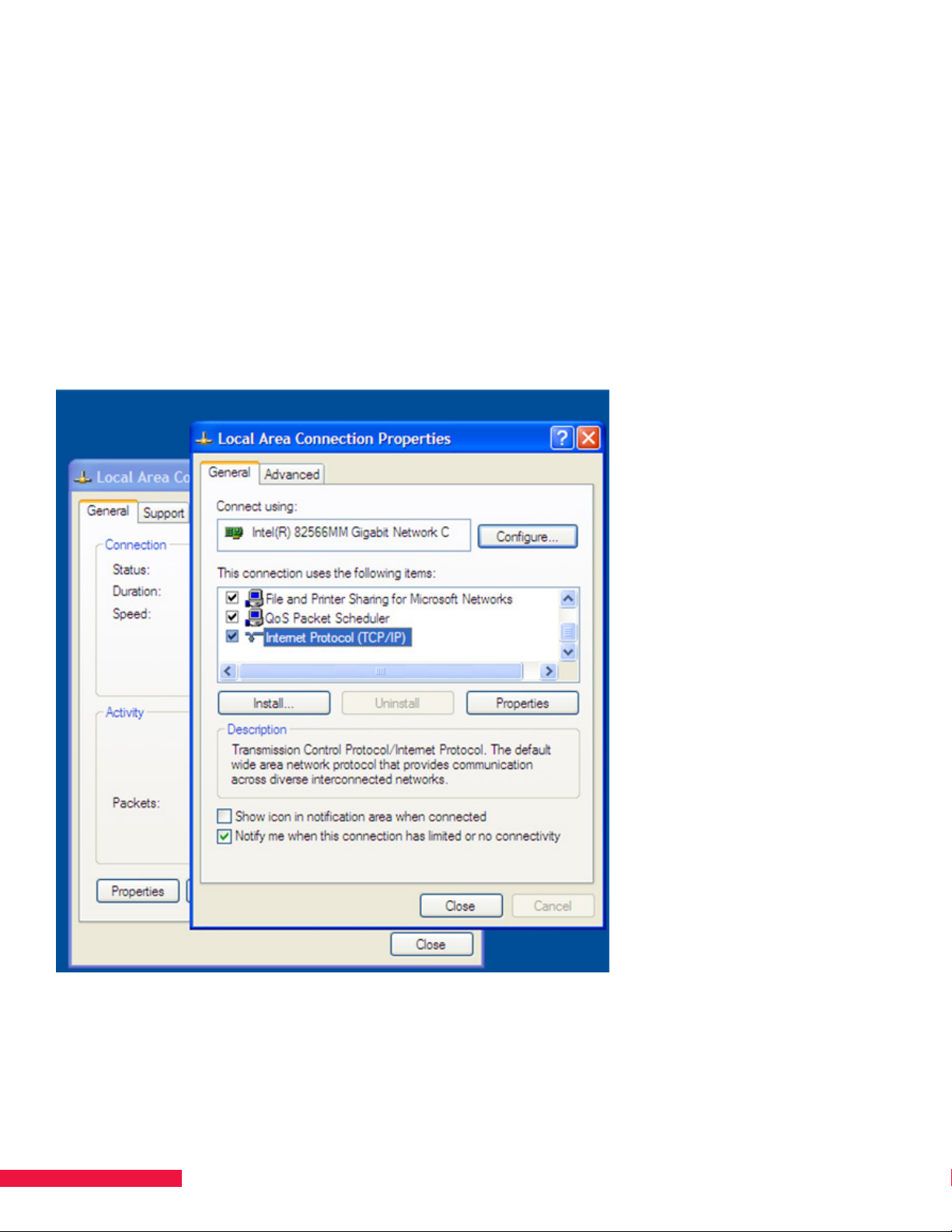
3. Check Internet Protocol (TCP/IP) and click Properties (See Figure 4.). The Internet Protocol (TCP/IP)
Properties window appears (See Figure 5.).
Figure 4. Configure Network - Select Internet Protocol (TCP/IP)
14
Page 15
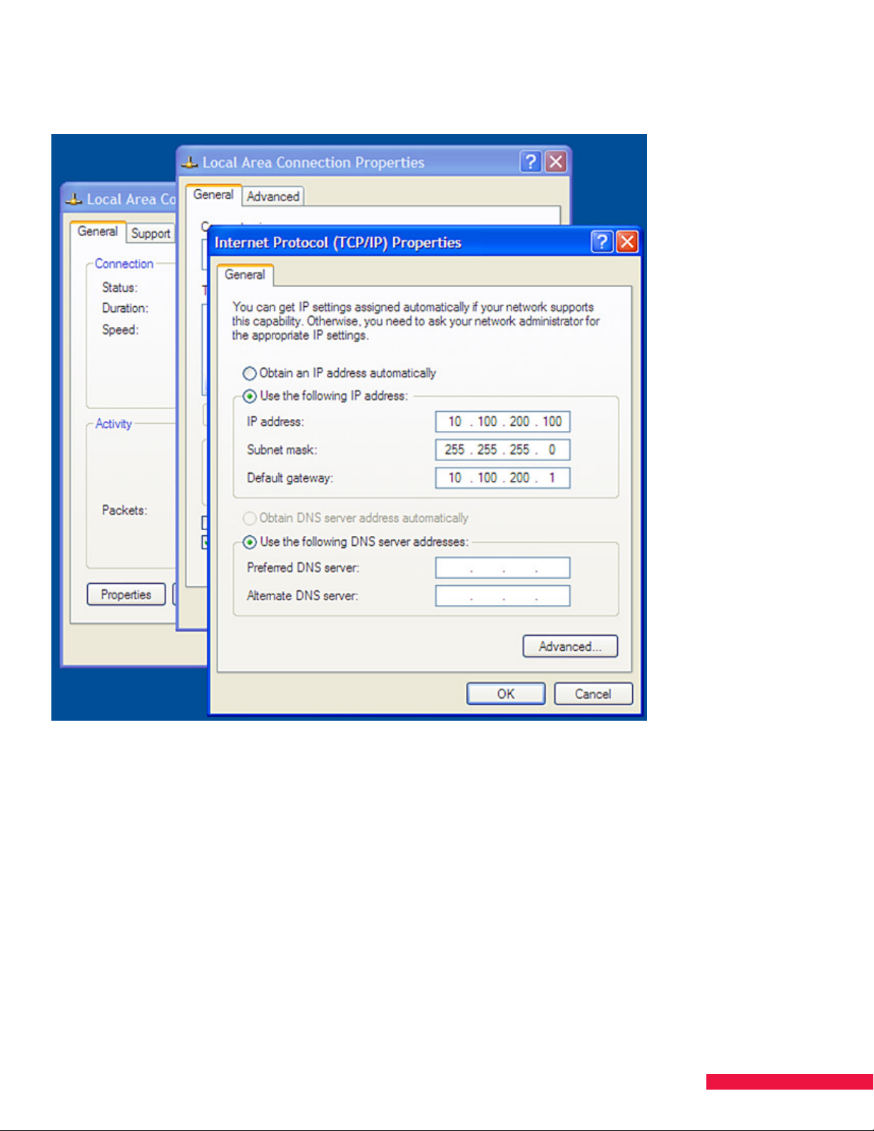
Figure 5. Internet Protocol (TCP/IP) Properties – Enter IP Address
4. Select the option Use the following IP address and enter the following:
IP Address = 10.100.200.100
Subnet Mask = 255.255.255.0
Default Gateway = 10.100.200.1
5. Click OK, then Close to complete the setup and exit.
15
Page 16
Establish Communication with SMARTBOX
4 LED Indicators
Data 1 (Ethernet)
Power
Supplies
Connect SMARTBOX to Ethernet
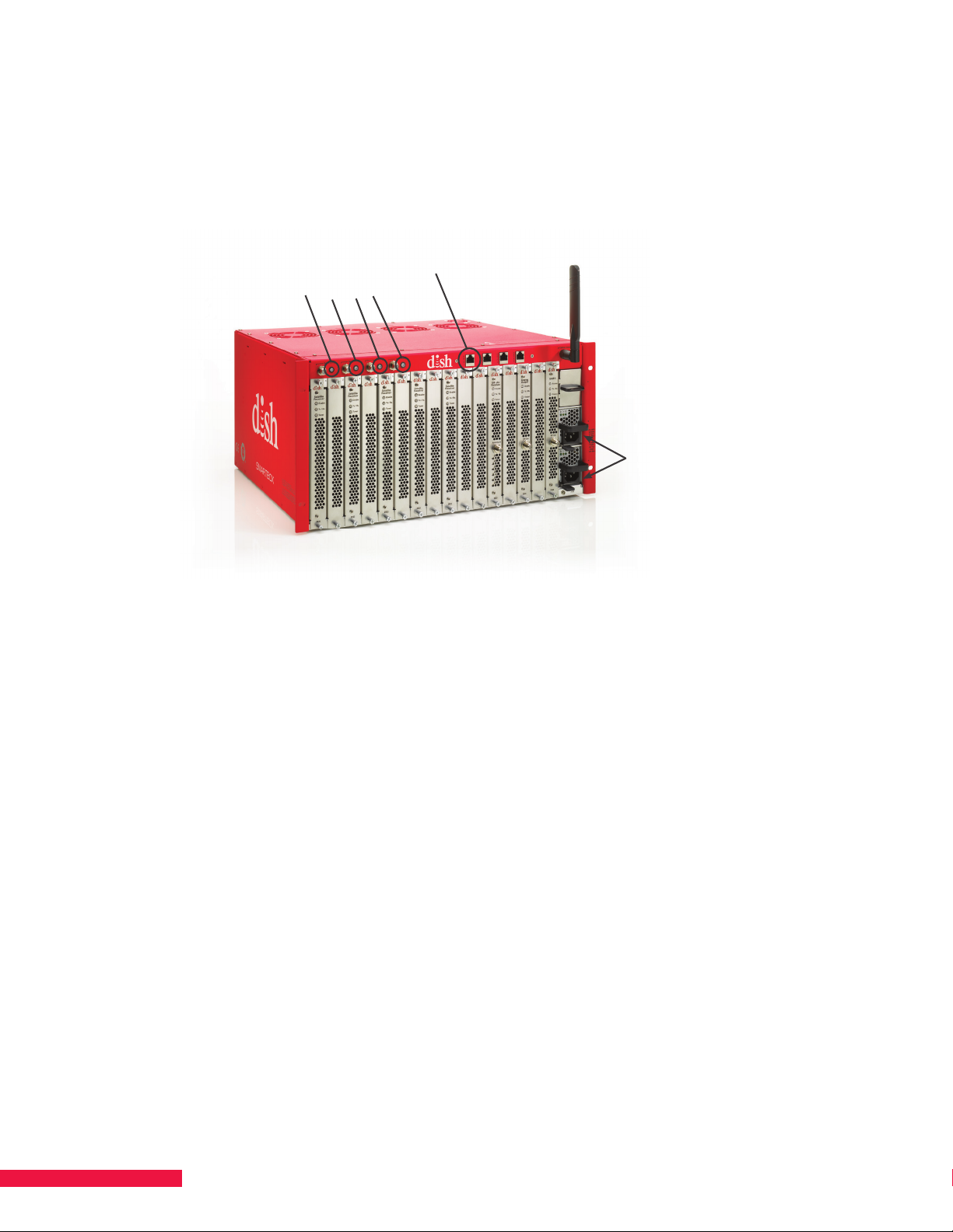
1. Connect an Ethernet cable between the port labeled Data 1 (located to the right of the DISH logo on the front
of SMARTBOX) and an Ethernet port on a router or computer (See Figure 6.).
Figure 6. Ethernet Port – Data 1
2. Plug the SMARTBOX power supply into an uninterruptible power supply (UPS) providing AC power.
The system powers on and self-boots.
• Four LED indicators located next to the satellite ports on the front of chassis blink during boot.
• LEDs turn solid when boot-up is complete. Please see Chapter 20 LED Information for more detailed
explanation of the dierent LED colors. System boot-up may take up to 5 minutes.
Connect Cables to Connectors and Install Cellular Antenna
1. Connect a cable from an external terrestrial antenna to the “Antenna In” connector on the front of the
ATSC blade (if installed). If more than one ATSC blade is installed, use a splitter to connect the blades
to the same antenna.
2. Connect the QAM blade output port to the cable plant. If SMARTBOX contains multiple output blades
(e.g., QAM and NTSC), use an external combiner to combine their signals on a single coax cable.
3. Screw the cellular antenna into the SMA connector located on the upper right corner of the front
of SMARTBOX. The cellular antenna is provided with the SMARTBOX chassis; however, depending on your
install, you may need to use a third-party antenna extender to achieve connectivity.
16
Page 17
Login to SMARTBOX
1. Open a web browser. Firefox®, Chrome™ and Safari® are recommended.
2. Enter 10.100.200.10 in the URL.
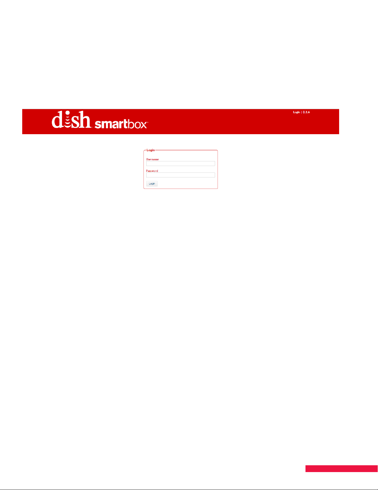
The DISH SMARTBOX Login Screen should appear (See Figure 7.). If it does not, verify that the IP address was
correctly entered in the previous steps for the URL and Network Configuration.
Figure 7. Login Screen
NOTE: By default, each SMARTBOX is configured with the IP address and settings:
IP Address = 10.100.200.10
Subnet Mask = 255.255.255.0
Default Gateway = 10.100.200.1
DHCP client = Disabled
If you change the default address for SMARTBOX, be sure to document the new address for future access.
3. Enter the default username and password:
Username = username
Password = password
4. Click Login.
The version of software that SMARTBOX is running is visible in the top right corner.
17
Page 18

Admin Tab
1. Once logged into the system you will be on the Configurations tab. Navigate to the Admin tab by clicking the
Admin tab on the right side of the screen.
2. For security purposes, on this tab you are able to change your username and password from the default
settings. Once changed, select Apply for it to take eect. Then record the new username and password.
3. Date & Time: This indicates the date and time of the ZIP code for where the SMARTBOX account was
authorized. The Master Blade Uptime indicates the time that the Master Blade has been running.
4. Management IP: This section contains the MAC address and allows the configuration of the SMARTBOX
Management IP settings so that remote access can be set up.
5. Content IP: This section allows you to configure the IP settings for when you are outputting content via IP. If
the switching network contains a router, a Content Address is required. The IP Address entered will indicate
the source of the content so that the network can properly filter the trac based on the source. It needs
to be a real address in the subnet from which the content is emanating. Speak to the network manager to
determine how the network is configured and what needs to be entered here.
NOTE: Ensure that the content and control interfaces are on separate subnets. As SMARTBOX is a single
device, the routing will become ambiguous and SMARTBOX will become unavailable.
6. The Download Data Model button under the CWMP section downloads the CWMP data model that allows
for remote monitoring via TR-069 in conjunction with an ACS.
7. If you need to restore SMARTBOX back to default settings, there are two options available; Restore to user
default settings and Restore to factory default settings.
NOTE: Both of these options restore SMARTBOX back to default settings; HOWEVER, the factory default will
also restore default IP settings and the user default will keep any changed IP settings.
8. The Download System Report button can be used to pull in the necessary file information to send to the
[email protected] mailbox for troubleshooting support.
Chassis Tab
1. Fan Statuses: This section indicates the speed of the five fans on the chassis. Fan 5 is the power supply fan
and will be spinning at a faster rate than the other fans.
2. Chassis Info: Contains info on the Serial Number and Part Number of the chassis.
3. Data Port: This section is where the data ports are configured. See Chapter 8 SPECIFY DATA PORT
CONTENT/CONTROL INTERFACE for more information.
4. L-Band Inputs: This section is where satellite feeds are configured and scanned. See section Enable Satellite
Inputs and Chapter 7 SCAN FOR SPOT BEAMS AND SATELLITE SERVICES for more information.
5. Power Supplies: This section provides information on the power supplies in the system, including the serial
numbers, the RPM of the individual power supply fans, temperature, voltage, and current.
6. Modem Info: This section displays information on the cellular modem, including the Modem Type, Serial
Number, SIM ICCID, Activation Status, Registration Status, Signal Strength, Manufacturer, Model, and
Software Version. The Signal Strength range will be between 0 and 31, with the 31 being the highest level.
When the signal level is not known, not detectable, or currently not available, 99 is reported.
18
Page 19
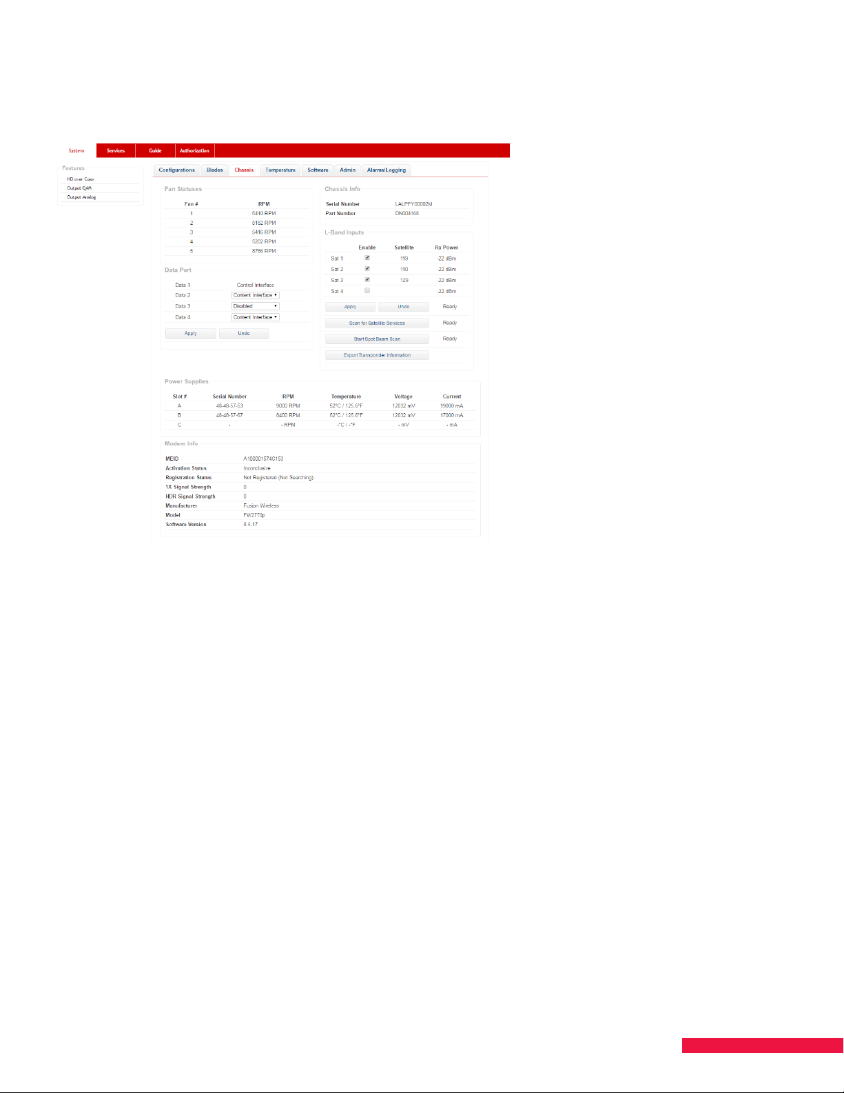
Enable Satellite Inputs
1. Click the Chassis tab (See Figure 8.) .
Figure 8. Chassis Tab - Enable Satellites
2. Under L-Band Inputs, click the check boxes in the Enable column. Check a box for each satellite connected
to the SMARTBOX satellite inputs (Sat ports 1-4).
3. Click the Apply button under the Enable column. If a message regarding disruption of satellite services
appears, click OK. (Cancel allows you to stop the process.) The status of the satellite discovery appears to
the right of the Apply and Undo buttons; the status may reflect Waiting, Not Ready, Ready or % Complete. It
takes approximately five minutes for the process to complete.
4. Click Export Transponder Information. This file will verify visibility of transponders on each applied
satellite feed. This file is updated when a satellite scan is run.
NOTES:
• RX Power indicates total satellite power — not individual transponders.
• The ideal signal range is between -20 dBm and -35 dBm, with each orbital being within ± 5 dBm of each other.
Larger dierences can result in intermittent performance. -62 dBm is the floor; if you see -62 dBm, there is no
signal being detected.
When deploying SMARTBOX at a customer’s site, take the following steps to ensure the orbital information is
correct.
1. Uncheck the satellite feeds then click Apply.
2. If the scan is stuck at “Waiting” or a specific percentage for more than 90 seconds, reboot the system.
a. If you have to reboot, when the system comes up you will see that the orbitals are still there, but
unchecked. Click Apply again.
3. Once all the feeds are unselected and no orbitals are listed, reselect the ones with connections then click
Apply.
4. Wait for that to complete, then confirm that all blades have tuner lock.
19
Page 20
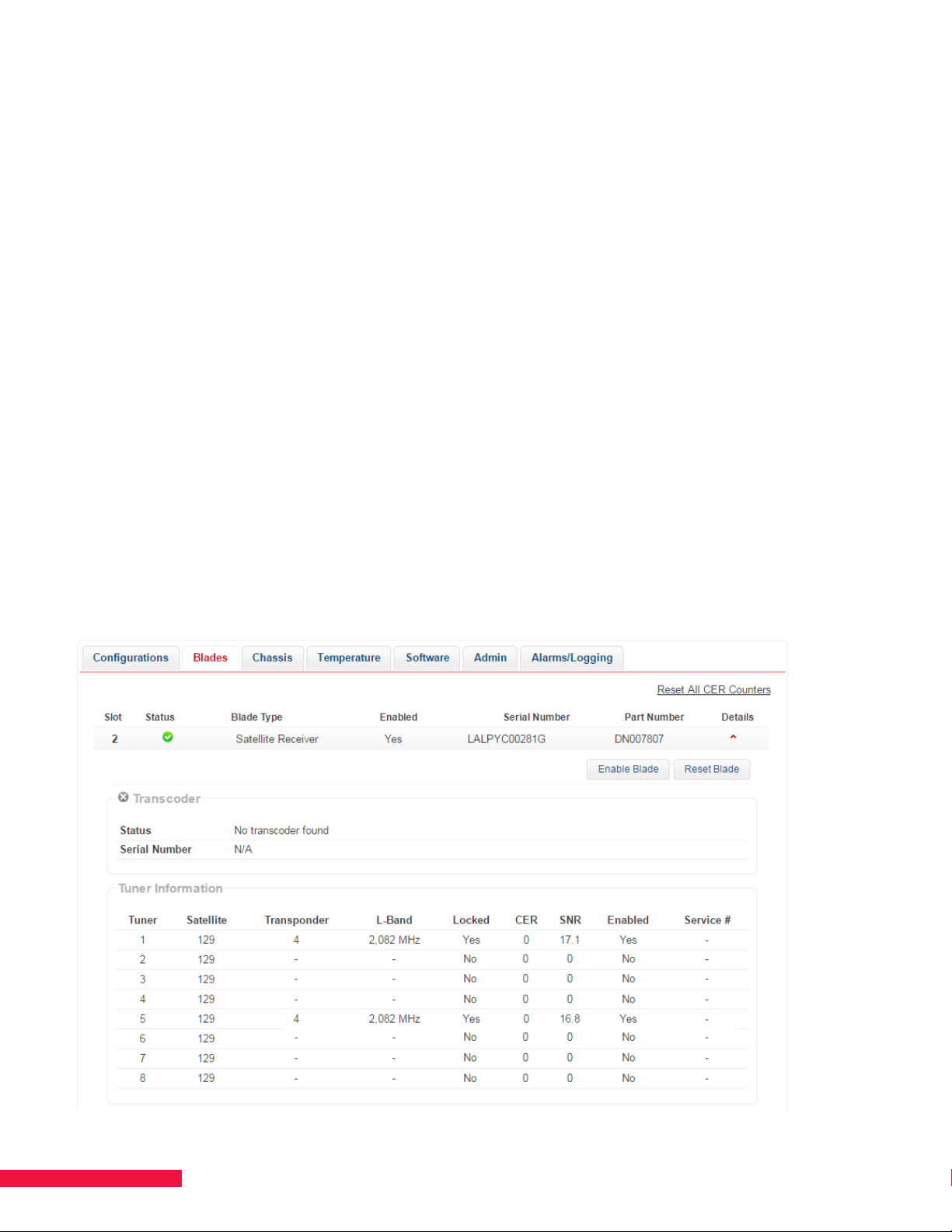
Verify Tuners Lock
1. Click the Blades tab (See Figure 9.).
2. Click the down-arrow under Details for the satellite blade.
3. Verify that one tuner in each set (tuner set 1-4 and tuner set 5-8) is locked. Examples of locked tuner pairs:
1 and 5, 4 and 5, 2 and 7.
If not locked, return to the Chassis tab and verify that the satellites have been enabled and click Apply again
and wait for the scan to complete. Return to the Blades tab and verify.
NOTES:
• Transcoder - When the Details on the Blades tab are expanded, you can see whether a transcoder is present
on the blade or not. A gray X indicates Not Present; a green check-mark indicates Present.
• Descrambling Status is located below the Tuner Information.
– “Granted” indicates the ProCam is authorized for service.
– “Denied” indicates the ProCam is not authorized.
– “Free” means the service does not require authorization and is free to all receivers.
– “SC Blackout” means service is blacked out due to programming agreements.
• Reset Blade button allows you to reboot the specific blade as opposed to rebooting the entire system (Admin
tab—> Reboot System button). If you attempt to reboot the master blade, an alert warning occurs indicating
that the system will lose connection until another blade becomes master or the blade comes back up.
• Disable Blade button removes the blade from available resources to assign services to. The blade is still
powered and visible in the interface, but no services will be assigned to it.
Figure 9. Locked Tuners
20
Page 21

Download Software from Satellite
1. On the System page, click the Software tab.
2. In the Automatic Update section change the Configuration drop down box to Install update when
available then select Apply.
3. Select Check for update now.
4. SMARTBOX will check the software available from the satellite for most current version.
5. If a newer version of software is available, the system will begin the download to all blades.
6. When the download is complete and all blades/devices instruct you to perform a reboot, click the Admin
tab and select Reboot System. You can also do a hard reboot by unplugging SMARTBOX, waiting a few
seconds, and then plugging it back in.
7. Log in, then click the System - > Software tab. Check that the blades have the same version of software.
If there is an error when attempting to download the software, confirm that the blades have tuner lock again, and
repeat the steps to initiate the download. If the issue continues, contact DISH Support.
Update Settings for Automatic Update
1. Choose from two options:
a. Install update when available – this option will use the time you specify to check the satellite to always
be on the most current software. If a new software is available the system will download the software
and reboot at a separate time you can also specify. A software download from the satellite will take 30
minutes.
b. Check for update only – this option will use the time you specify to check the satellite to always be aware
of the most current software available.
Download Software from SFTP
A secure file transfer protocol (SFTP) program, such as FilezillaTM, WinSCPTM or SmartftpTM, is needed to manually
download SMARTBOX software from the DISH website – basic ftp programs will not work.
1. Open the SFTP program and enter the address: dishsftp.dish.com
2. Enter the username: smartbox_vendor.
3. Enter the password, which can be found on the SMARTBOX Community on DISH Portal.
4. Select the filename SMARTBOX-0.x.x.zip (the latest version) and download it to the PC. Transfer the file in
binary mode, not ASCII.
5. Unzip the file and move it to the desired folder on the PC that will be used to operate SMARTBOX.
21
Page 22
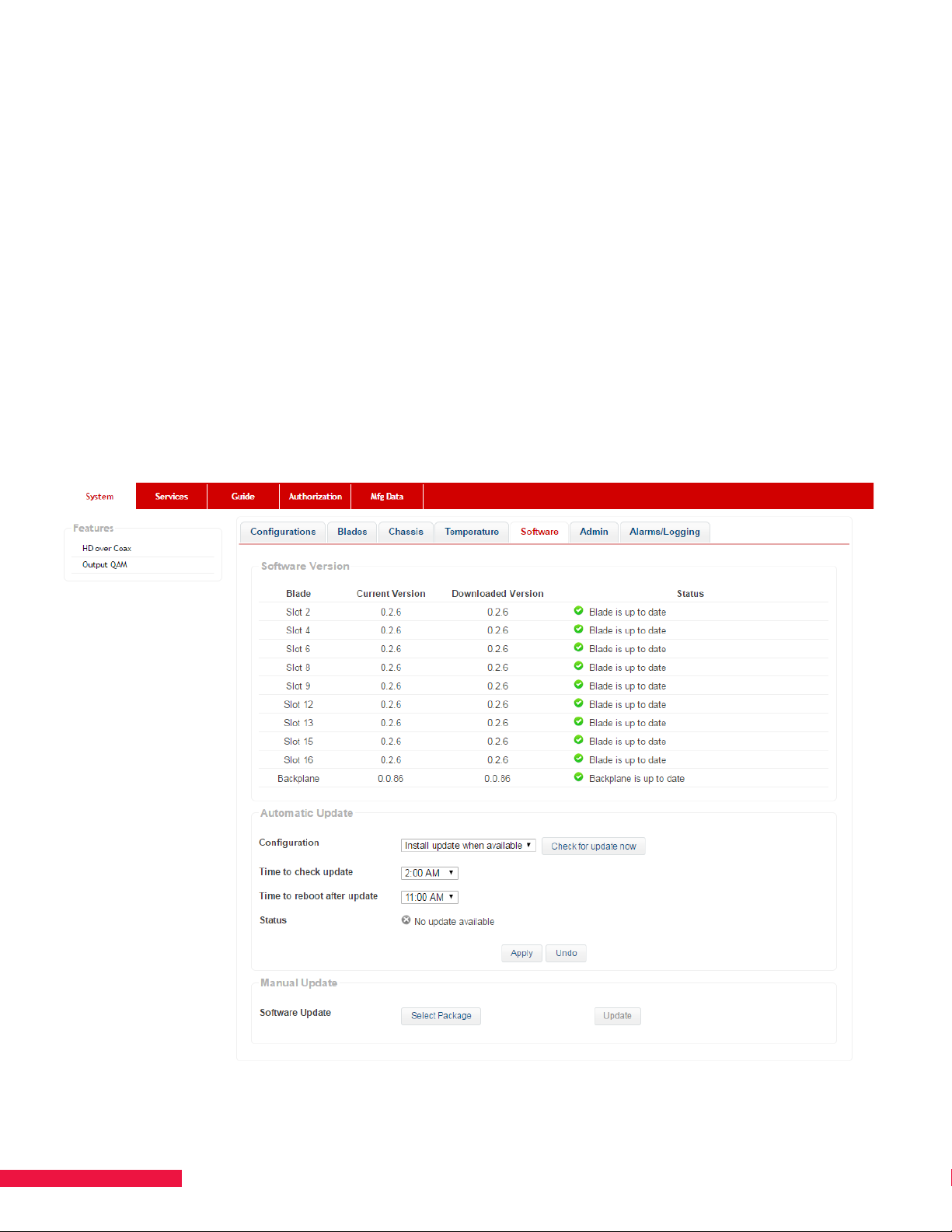
Manually Update Software
1. On the System page, click the Software tab.
2. In the Manual Update section near the bottom of the page, click Select Package (See Figure 10.).
3. Navigate to the directory where the unzipped file resides. Select the file and click Update.
a. Once initiated, the software update takes approximately 10 minutes. When complete, the displayed
downloaded versions should match the release notes, found on DISH Portal.
4. When the download is complete, click the Admin tab and select Reboot System. You can also do a hard
reboot by unplugging SMARTBOX, waiting a few seconds, and then plugging it back in.
5. Log in, then click the System - > Software tab. Check that the blades have the same version of software and
that the version is the same as the package downloaded from the SFTP site.
If there is an error when attempting to upload the software, confirm that the computer is connected to the system,
and repeat the steps to initiate the download. If a blade fails to update, reset that blade, wait for it to boot back up,
then try re-applying the software package. If your issues continue, contact DISH Support.
Figure 10. Update Software
22
Page 23

CHAPTER 5 FEATUREENABLING CODES
The control of incoming satellite data is handled by the following product-enabling features:
DRM Lynk allows the output of video with Samsung’s Lynk Digital Rights Management (DRM) encryption. To use
this DRM, a licensed Lynk key server is needed.
DRM Pro:Idiom allows the output of video with Zenith Pro:Idiom DRM encryption. To use this DRM, a one-time
licensing fee per chassis will be charged to the account.
DRM Verimatrix allows the output of video with Verimatrix VCAS DRM encryption. To use this DRM, a licensed
Verimatrix key server is needed.
DRM Digital Upgrade allows the output of the DISH QAM mode of operations for use with DISH receivers at
each television.
HD Over Coax allows the output of digital video with HD Over Coax Watermarking. This feature code must be
used in conjunction with Output QAM. There are programming restrictions when using this output format. The
format is in MPEG-2 video with AC3 2.0 audio with PSIP information.
Output Analog enables the unit to output an analog signal using an installed NTSC blade.
Output IP enables the unit to output an IP signal using data ports 2-4. This code needs to be used in conjunction
with DRM.
Output QAM enables the unit to output a QAM signal using an installed QAM blade (16, 48, or 96). This code
needs to be used in conjunction with DRM (HD Over Coax, DRM Lynk, DRM Pro:Idiom, DRM Verimatrix or DRM
Digital Upgrade).
Simulcrypt allows for secure connection between
by-case approval). Currently used in Enterprise and Healthcare verticals.
EVOLVE enables the feature set required for the use of the EVOLVE Set Top Box. The EVOLVE authorization
automatically applies the HTVConnect authorization, including the one-time $1,000 charge upon activation.
Note, the HTVConnect authorization will not display on the SMARTBOX UI, it will only be visible within
Salesforce.
For any questions regarding pricing or available feature options, please speak to your Area Sales Manager
(ASM).
SMARTBOX
and third-party server (server used requires case-
23
Page 24
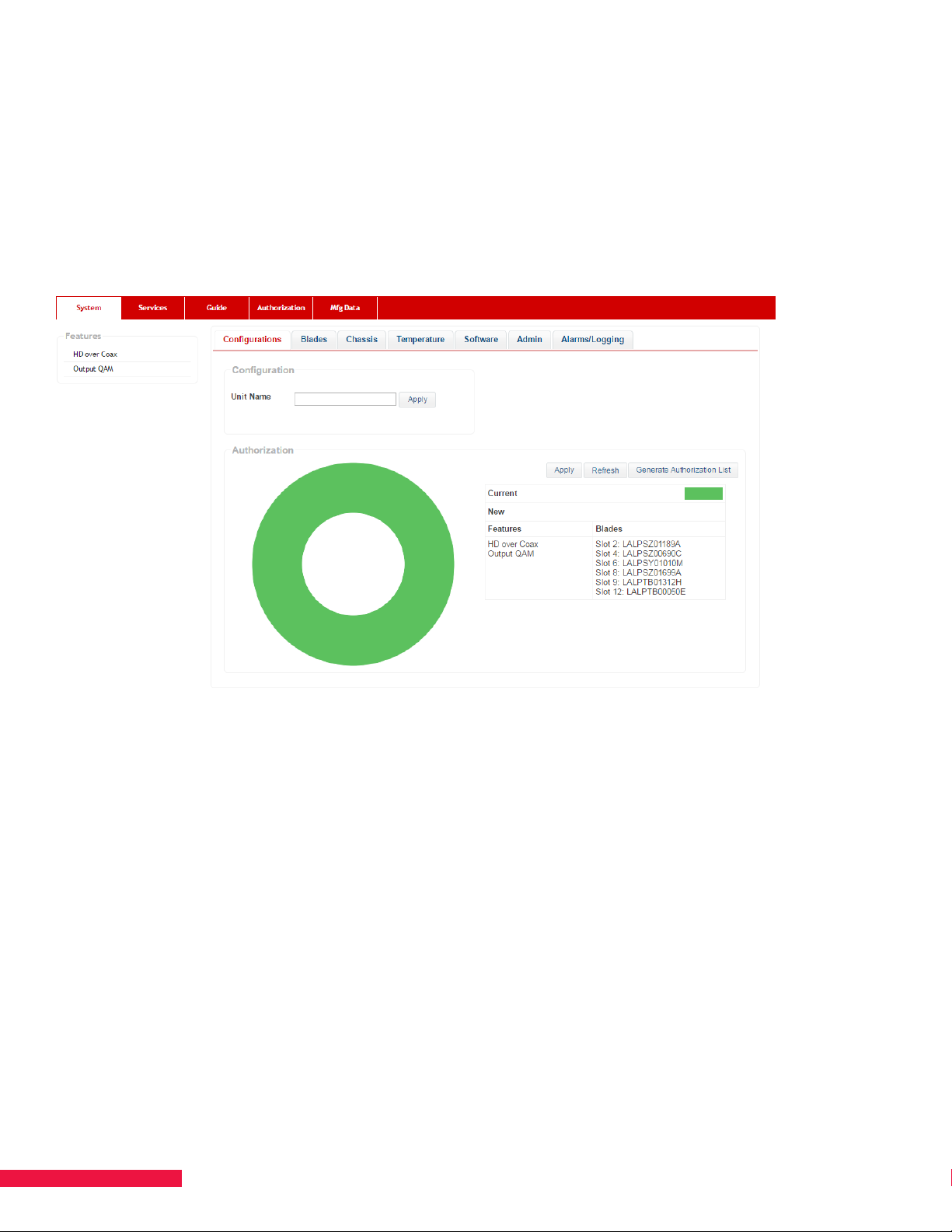
CHAPTER 6 AUTHORIZE SMARTBOX
Authorization of SMARTBOX is a simple process that entails generating a list of information related to the
hardware components and providing this information to DISH. Once received and processed by DISH, the
authorization of SMARTBOX occurs automatically. Execute the following steps to initiate authorization.
1. Validate that each satellite receiver blade has tuner lock as referenced in Chapter 4 UPDATE SOFTWARE.
2. Click the Configurations tab (See Figure 11.).
Figure 11. Configurations Tab
3. Click Generate Authorization List. A comma-separated values (.csv) file is downloaded to your computer.
The file contains a list of the chassis number, the blade serial numbers, the receiver CAIDs and the
SmartCard numbers (See Figure 12.).
NOTES:
• Authorization can take up to 24 hours. SMARTBOX needs to remain powered on and locked to satellites for
authorization to be completed.
• The Refresh button updates frequently changing information, such as signal strength. Static information such
as serial numbers do not get “refreshed.”
• Once the file has been downloaded, open it in Excel to verify that it has accurately populated the necessary
information (the correct number of CAIDs and SmartCards). Only Satellite Receiver Blades have ProCAMs with
CAIDs and SmartCards. If a blade has not fully booted before generating this file, its information will not be
included.
24
Page 25
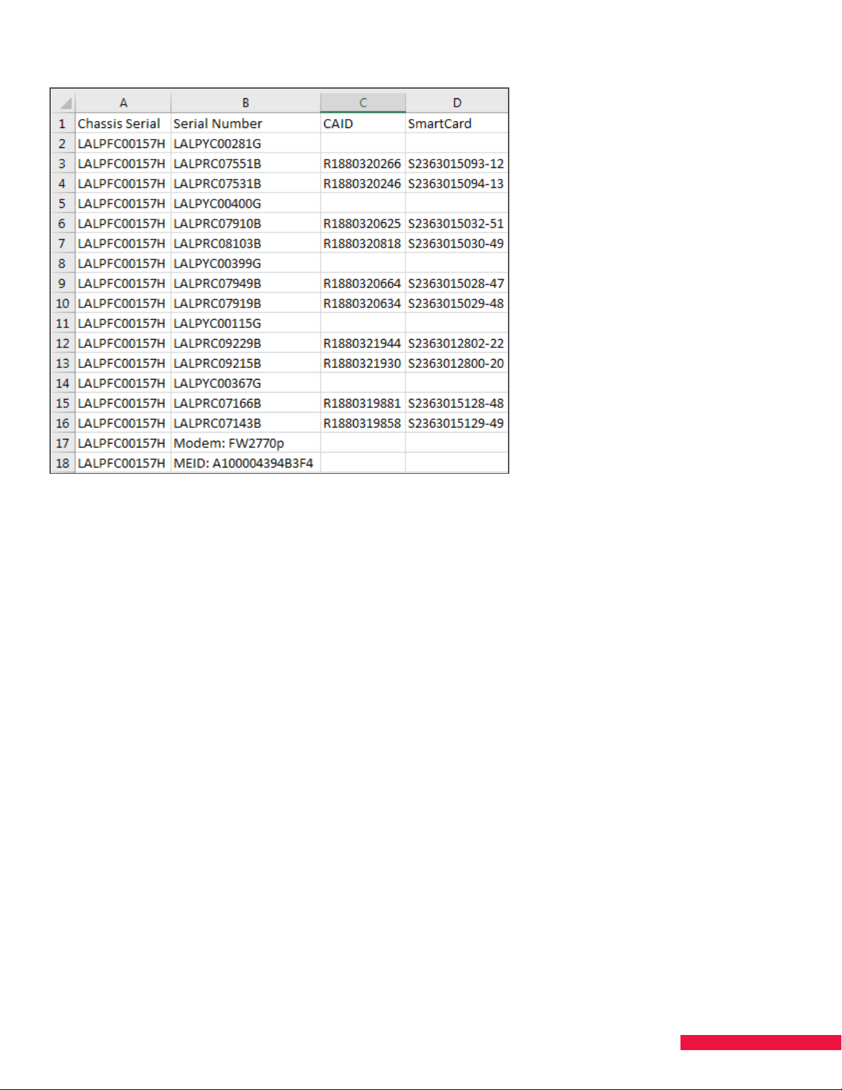
Figure 12. Sample .csv File
3. Upload the list to Salesforce and fill out the activation form for processing. For assistance, contact your
Area Sales Manager (ASM).
Authorization – 100%
If the system completes the authorization process without error, the donut on the Configurations tab turns a solid
color. The color represents the authorized set. If there is more than one color, see the next section, Authorization
- Less Than 100%.
Once authorization is complete, a list of enabled features, blade slot numbers and serial numbers appears on the
Configurations tab in the Features and Blades columns.
On the Blades tab, click Details to review blade-specific information. Information regarding authentication
of ProCAMs, pairing of SmartCards and SmartCard status can be viewed there. The status of ProCAMs and
SmartCards are shown with a green checkmark or a red or orange caution sign. A red or orange caution sign is
an indication of an error.
To accept the configuration:
1. Click the donut. A color bar matching the selection appears in the field to the right of New.
2. Click Apply to accept the authorization selected. A color bar matching the applied selection will appear in
the field to the right of Current.
NOTE: SMARTBOX will not be able to output services or initiate a Scan for Satellite Services until the donut has
been applied and the authorizations selected.
25
Page 26
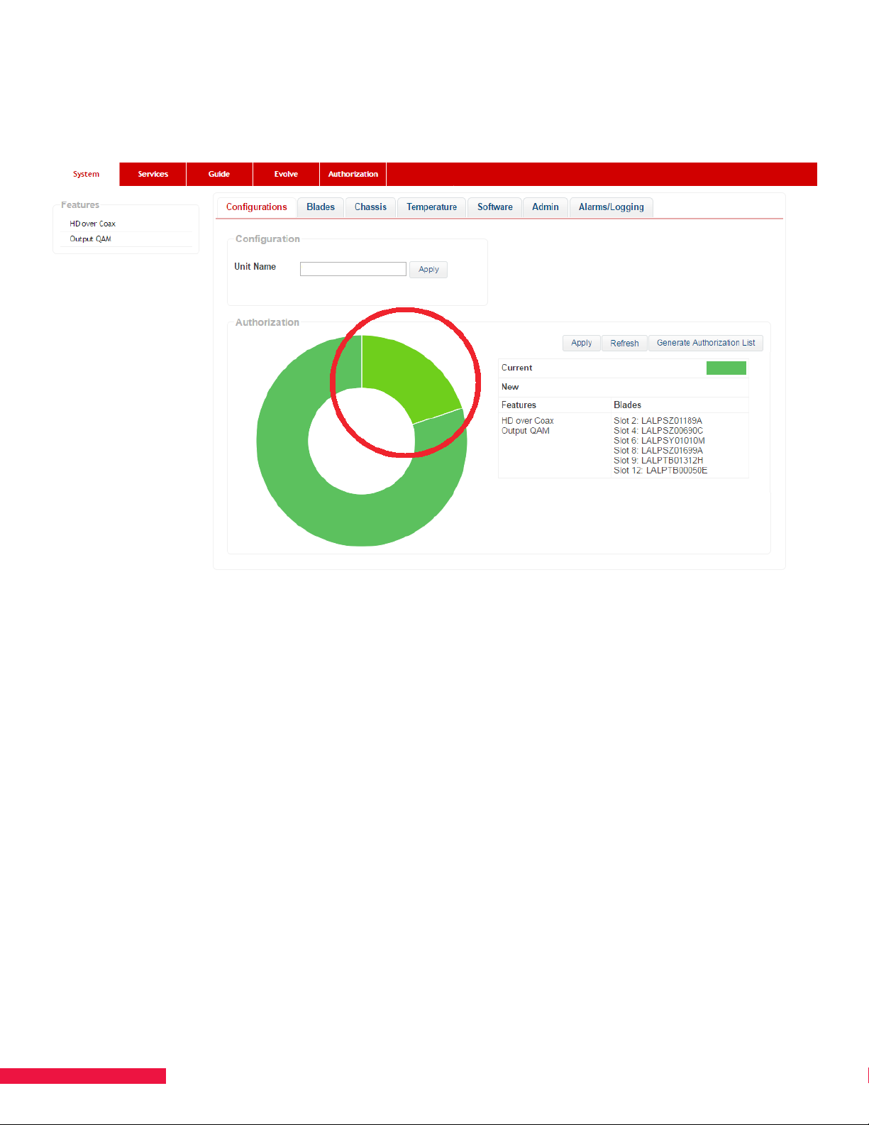
Authorization – Less Than 100%
If authorization fails for a blade, a second color representing the failed blade(s) displays on the donut
(See Figure 13.).
Figure 13. Authorization - Less than 100%
If this happens, check for appropriate signal levels and signal quality at the inputs to SMARTBOX. Validate that
each satellite receiver blade has tuner lock as referenced in Chapter 4 UPDATE SOFTWARE. If all specifications
for signal level and quality are met, contact DISH Support to assist you.
To begin configuring your system while the authorizations get corrected, follow the steps below:
1. Click the part of the donut representing the correctly authorized components.
2. Click Apply to confirm the configuration to be used by your SMARTBOX. A color bar matching the authorized
part of the donut appears in the Current field to the right of the donut.
26
Page 27
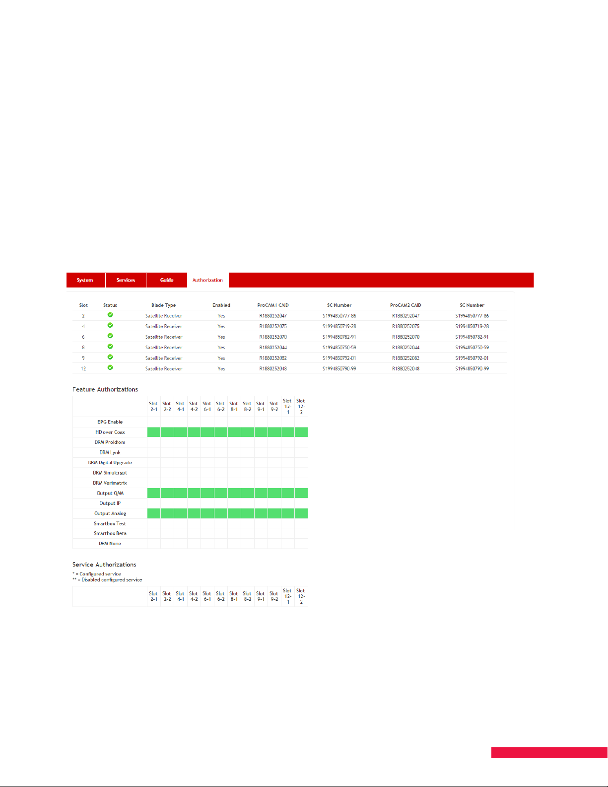
Authorization Page
Use the Authorization page to see a detailed view of information for the satellite receiver blades (See Figure 14.).
This is a quick way to see if the blades are in agreement.
The Authorization page includes information on:
• Blade Status
• ProCam1/ProCam2 CAIDs and SmartCard Numbers
• Features authorized for each ProCam
• Services authorized for each ProCam
Each of the ProCAMs should be authorized the same. Any mismatch will show as red for the ProCAMs that are
not authorized for that feature or service. If there is a mismatch, run a scan for satellite services and wait for it to
complete. If the issue persists, contact DISH Support.
Figure 14. Authorization Page
27
Page 28
CHAPTER 7 SCAN FOR SPOT BEAMS AND
SATELLITE SERVICES
Scanning for spot beams updates the list of visible services that needs to be updated when changing local
markets (known as DMAs); scanning for satellite services checks which of those services your account is
authorized for.
1. Click the Chassis tab.
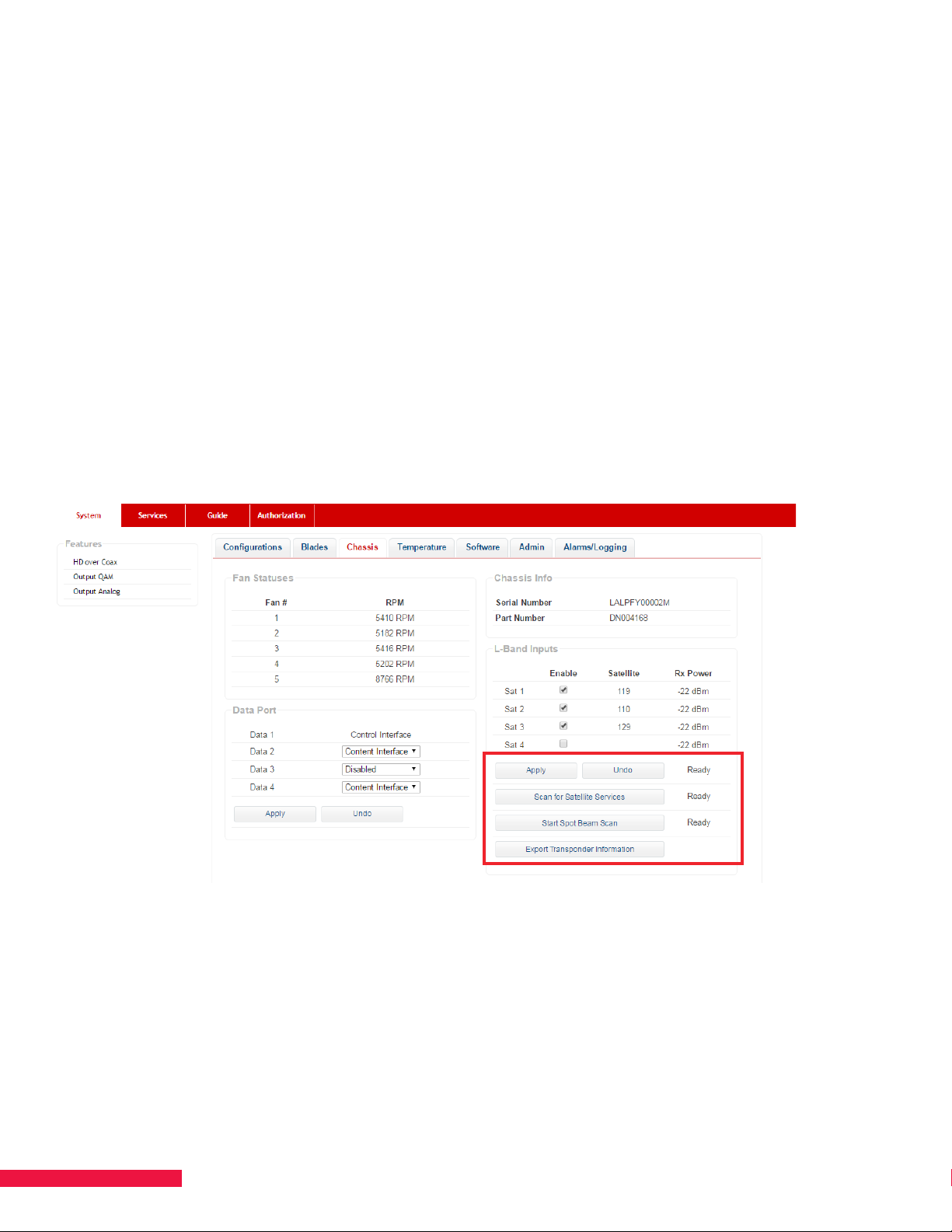
2. If the satellite feeds were scanned in a dierent location, click Start Spot Beam Scan. If the satellite feeds
were scanned in the current location, go to the next step. The status of the scan appears to the right of the
Apply and Undo buttons (See Figure 15.). Close the information message when the scan is complete.
The Spot Beam Scan will interrupt service output while the Network Information Table (NIT) is built. The NIT
describes which orbital/transponder each service is available on and is also built during the initial satellite
feed scan.
3. Click Scan for Satellite Services. The system will begin comparing the information in the NIT to the
Service Authorizations for each ProCAM. Once complete, the list of services for which your SMARTBOX is
authorized will be available on the Services page. This scan will not interrupt service.
Figure 15. Start Spot Beam Scan and Scan for Satellite Services
28
Page 29
CHAPTER 8 SPECIFY DATA PORT
CONTENT/CONTROL INTERFACE
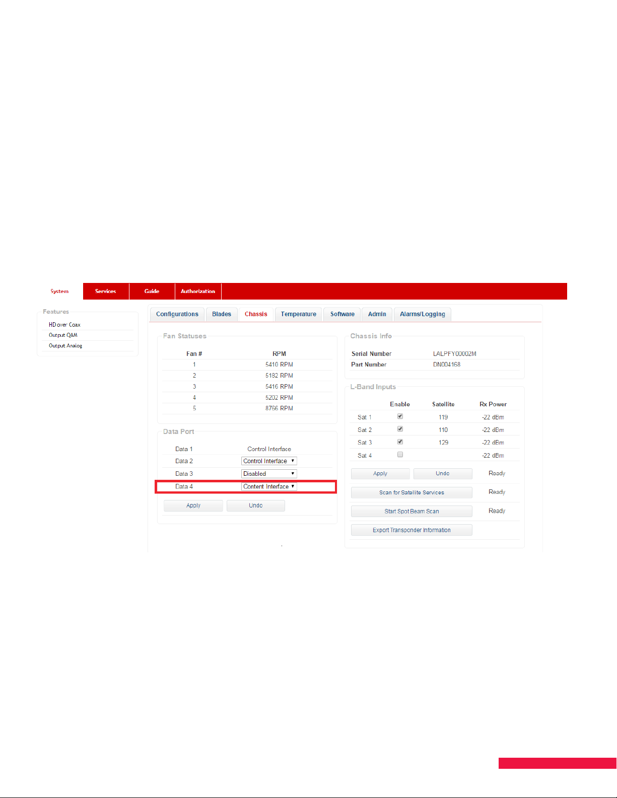
Data port 1 is automatically configured as a Control Port and cannot be changed. Data ports 2-4 may be
configured as nothing, additional Control Ports, or Content Ports. The configurations set for ports 2-4 will clear
during a user and factory default. Therefore, if remote access is desired, connect the remote access device to
port 1 and use the additional ports for connections with the site.
To input or output IP content, data ports 2-4 may also be configured as a Content Interface (See Figure 16.).
1. Click the Chassis tab.
2. Click the drop-down box next to the desired Data Port and select Content Interface or
Control Interface.
3. Click Apply. Set up all the data ports needed.
Figure 16. Data Port — Content Interface
29
Page 30
CHAPTER 9 ATSC INSTALLATION
Preface
The SMARTBOX ATSC blade is designed to receive eight (8) local (o-air) digital ATSC channels per blade and
distribute them throughout the property.
Receiving o-the-air digital TV stations is not as simple as putting up a TV antenna and hoping for the best. This
Chapter provides an overview of the required pre-installation planning processes, receive RF equipment selection,
installation process as well as the configuring and operating of your SMARTBOX unit and ATSC blade.
The following sections provide high-level guidance for receiving the desired ATSC services via SMARTBOX.
These sections are not comprehensive and not intended to instruct you on how to successfully install the
antenna. The in-depth details of these topics are presented in the SMARTBOX ATSC Best Practices document
that is available on the DISH Portal. Without reviewing, understanding, and applying the presented Best Practices
information, success in receiving all of the desired ATSC services at your customer’s sites are not likely to be
realized.
ATSC Input Signal Characteristics
RF signals received by the ATSC blade are measured by signal power and signal quality.
Signal power is typically measured in dBmV (or dBm).
Signal quality is typically measured as the signal-to-noise ratio (SNR) or the modulation error ratio (MER), both
of which are measured in dB. The SMARTBOX ATSC blade measures SNR and also maintains a count of Reed
Solomon Errors (shown as RS Uncorrected).
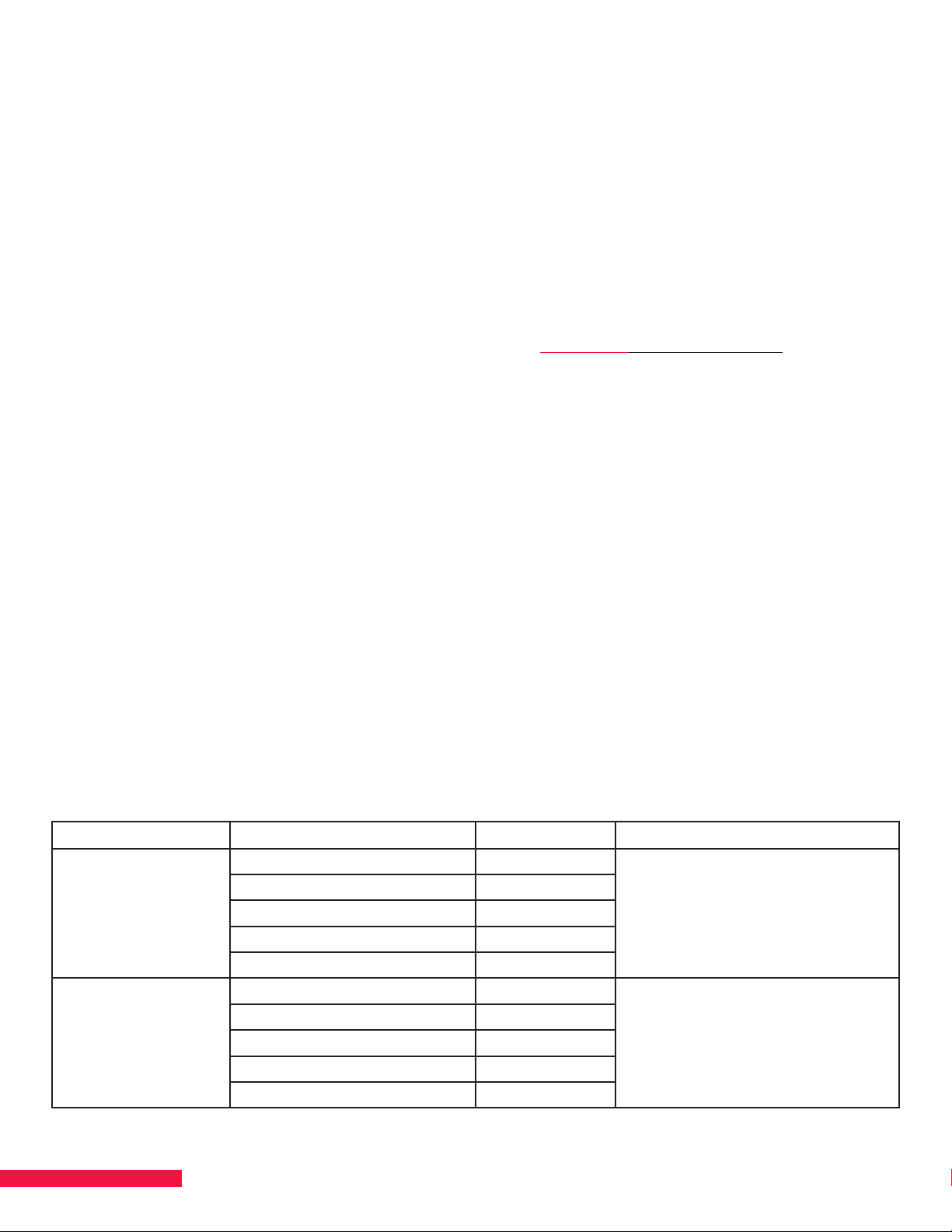
When tuning the antenna for best signal reception, signal quality (SNR) should always be considered more
important than signal strength (RSSI). The below table provides general guidelines on signal measurements and
how they correspond to acceptable performance (e.g., “poor” is not acceptable).
Signal Quality and Signal Level Measurements for ATSC Blade
Parameter Measurement Value Status Comment
> 22 Excellent Signal quality measurement (Note:
SNR (dB)
(Signal to Noise Ratio)
RSSI (dBm/dBmV)
20-22 Good
18-20 Acceptable
<18 Poor
18 (Low Bad)
> -35 / +13.8 Excellent
-36 to -50 / +12.8 to -1.3 Good
-50 to -75 / -1.3 to -26.3 Acceptable
-75 and lower+ / -26.3 to -36.3+ Poor
-80 / -31.3 (Low Bad)
when SNR < 18 (Poor) there is a high
likelihood that uncorrected channel
errors are occuring and that video
quality suers (e.g., pixilation)
Signal power (dBm) and
level (dBmV) measurement
30
Page 31

NOTES:
• If RSSI (signal level/power) is good/excellent and SNR (signal quality) is indicating a poor/acceptable
range measurement, then this condition is likely a good indication of local signal interference or multipath
degradation. Generally speaking, good signal power should equate to good signal quality.
• The RS Uncorrected count is accumulative. So, for example, a count of 3,000 errors over days/weeks/months
isn’t necessarily bad. But, that same error count within 60 minutes indicates that signal quality is suering and
likely the SNR is poor.
• No more than two ATSC services should be configured per QAM channel. For additional ATSC service
mapping guidance, refer to “Chapter 11 Map Service”.
Antenna(s) Installation
No single tower broadcasts all services. Most markets have 3+ towers each broadcasting select virtual channels.
This complexity requires a proper pre-installation site survey to determine the necessary antenna arc, transmitting
tower(s) distances and signal power, how many and type(s) or antenna needed, etc. to ensure the desired
channels can be received. Here are a few key tips to adhere to:
Antenna(s) and Amplification Selection and Ramifications
There are various antenna types: omni-, uni-, and bi-directional, pre-amped, antennas with filters for certain
frequencies, etc.
There are various amplification types: built-in, pre-, mast-, and distribution amps.
You must research which type(s) of antenna and amps are needed at each property. For example, the antenna
type/gain should be appropriately matched to for the transmit power and distance from the broadcast tower. This
avoids over/under-loading the RF “front end” of the ATSC receiver blade. For example, using a high gain antenna
(25 dBi+) with an amplifier (+20 dB) to receive a powerful 1MW (e.g., 1,000 KW) VHF transmitter that is located 10
miles will likely cause overloading and poor receiver performance.
Depending on the quantity and/or type of antenna installed, additional equipment may be necessary to complete
the installation. For example, a signal combiners or splitters may be needed. Be mindful of the type of combiner
or splitter used. Failure to do so will result in a higher noise floor, increased risk of interfering signals, or lead to
complete signal loss. Only combiners specifically designed for use with ATSC antennas should be used.
31
Page 32

Aiming Antennas
Here are a few high-level antenna installation steps to adhere to:
1. During the installation, use a good signal meter which can measure both the signal level and the signal quality.
While aiming, you should prioritize signal quality over signal strength. Better quality is more important than
receiving stronger signals. Analyze signal QUALITY by measuring either the MER or SNR level.
2. Install the antenna as high as possible. The higher the antenna, the fewer obstructions exist in the signal path
and the lower the impact from ground reflections will be. However, taller masts are more susceptible sway
and being “de-tuned” by wind gusts. Guidewires and similar support should be considered.
3. For sites where direct line-of site isn’t possible, you’ll need to try several dierent antenna locations. The
optimal placement may or may not require pointing the antenna directly at the broadcast tower. Aiming the
antenna toward a reflection point may provide an improvement.
4. Slowly rotate the antenna to the left and right to find the direction with the highest signal quality for each
desired channel. Leave the antenna in the position which provides the best overall signal quality for the
desired channels. This process likely will involve moving the antenna to dierent locations on the roof or
property as even a 5-foot move can significantly improve signal quality.
Additional installation steps are outlined in the best practices document.
32
Page 33
ATSC GUI Interface
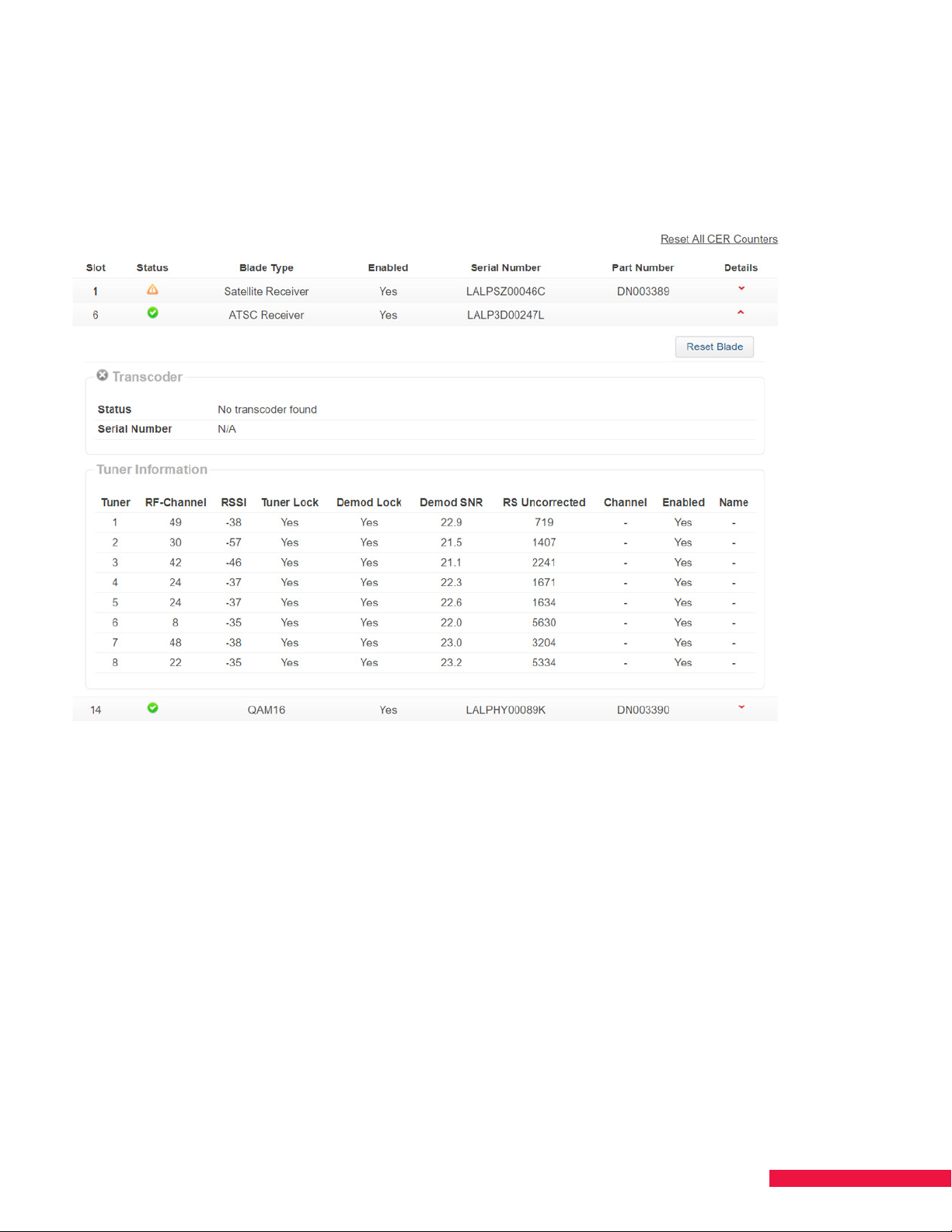
The ATSC blade user interface is found on the System/Blades tab. For information by tuner, click on the “Details”
down arrow located to the far for each particular ATSC Blade. (See Figure 17.).
Figure 17: ATSC Blade GUI Interface
The above figure shows eight tuners that have been configured. If a tuner has yet to be assigned a channel, the
data for that tuner will display a “0” or remain blank.
33
Page 34
BULK OPERATIONAL MODE
CHAPTER 10 SET UP CAS SERVER
When a CAS server is used to host Verimatrix, Lynk, or Simulcrypt, perform the following steps. Otherwise,
proceed with Chapter 11 MAP SERVICES.
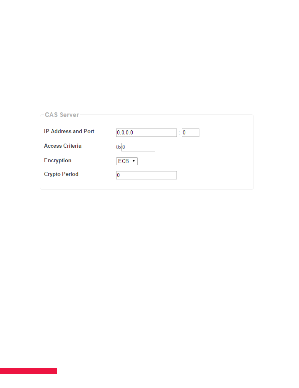
1. On the System page, click Admin (See Figure 18.).
Figure 18. CAS Server Configuration
2. Under CAS Server, enter the IP Address and Port for the server hosting Verimatrix or Lynk,
or Simulcrypt.
3. Enter the Access Criteria—it must be in the form of a 32-bit hexadecimal number (e.g., 0x00000400).
Verimatrix encryption typically requires 0x3 to be entered while Lynk encryption typically requires 0x0.
4. Select the desired encryption, either EBC or CBC. Verimatrix encryption typically requires EBC to be
entered while Lynk encryption typically requires CBC.
5. Specify the Crypto Period in seconds. This is the time between codeword changes.
6. Click Apply to save changes, then, under Actions, click Reboot the System to make the changes
eective.
NOTE: If SMARTBOX is unable to access the Verimatrix or Lynk server, it continues to use the current codeword
until the server can be accessed again or a timeout period occurs. The timeout is 48 hours. This means that if the
server cannot be accessed for 48 hours, the services being output with Verimatrix or Lynk encryption will no longer
be output.
34
Page 35

CHAPTER 11 MAP SERVICES
The contents of the Services list (Source/Name) depends on input to SMARTBOX and the services authorized
by DISH. Options found on the Services page allow for services from satellite and ATSC to be enabled and/or
updated. Options are also provided to map the services to output channels and to set up a IP Input (limit four) and
a Program Guide.
The following options are available under Actions on the Services page (See Figure 19.):
• Apply — applies all changes made to the Details of each service. Be sure to click this when you have
completed changes.
• Undo Changes — deletes any recent changes made that have not been confirmed by the action of clicking
the Apply button.
• Quick Add — allows you to configure an individual service that the system is authorized for.
• Add IP Input — allows you to add up to four IP inputs (AKA Welcome Channels) for QAM output.
• Add EAS Input — allows you to add the Monroe R189 EAS (Emergency Alert System) input.
• Scan for Satellite Services — allows you to refresh the list of authorized satellite services.
• Scan for ATSC Services — allows you to scan for available ATSC services if an ATSC receiver blade and
antenna are installed.
• Remove All Services — allows you to remove all configured settings for services; the list of authorized
services will remain but will default to the pre-configured state.
The Information section shows how many services are available for configuration sorted by the source.
The following options are available under Filter:
• Expand All – opens the Details for every service listed under the current filters.
• Collapse All – closes the Details for every service listed under the current filters.
• Source Filter Dropdown – filters services based on the input source.
• Configured Services Checkbox – filters the service list so that only configured services are shown.
• Search – searches for call sign or service number entered into field.
• By Letter Filter – filters services based on first letter of call sign.
35
Page 36
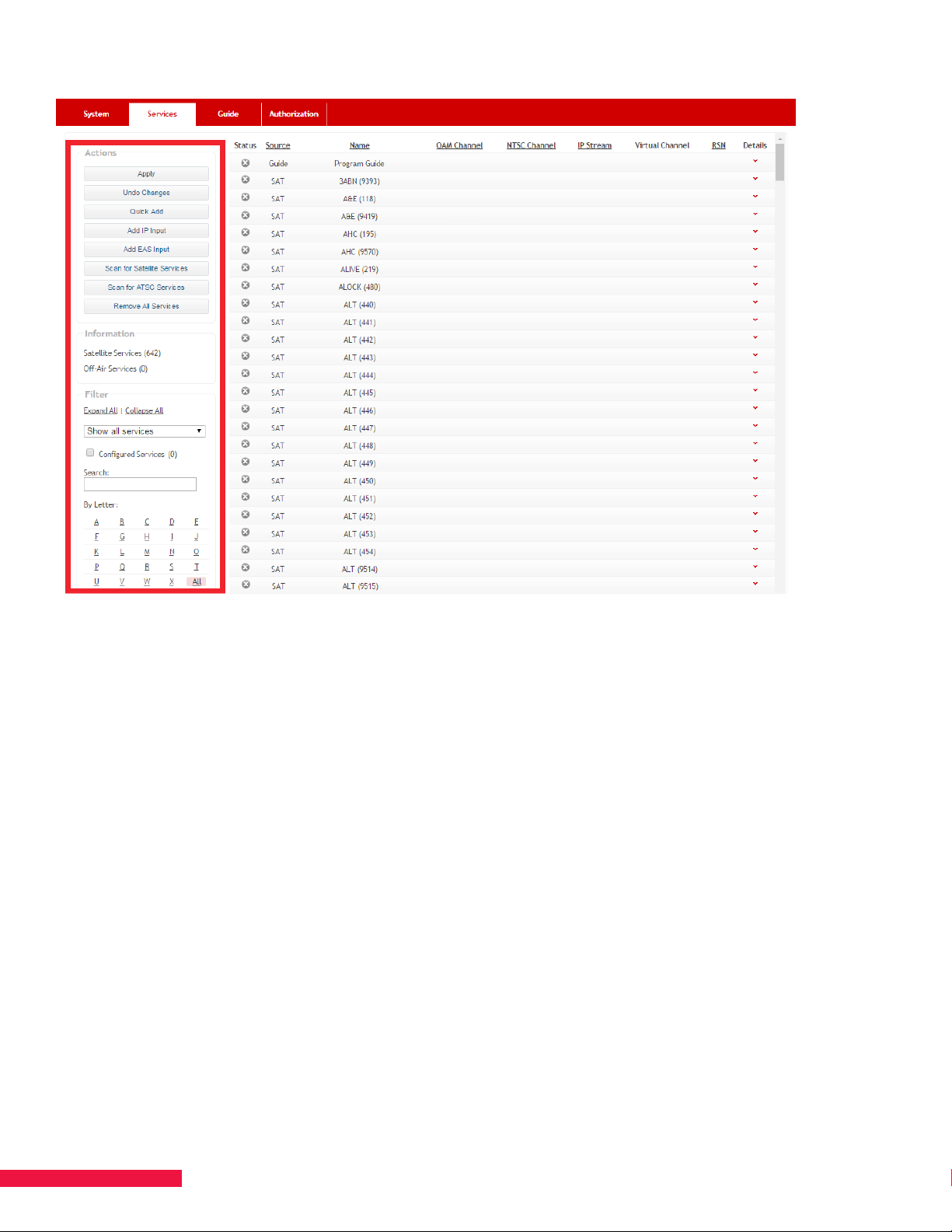
Figure 19. Services Page Options
Configuration File
If you have a previously saved configuration file you can select the file by clicking the Select Service Config File
button then select the file from its location on your computer. Once selected, be sure to click the Apply Selected
File button and then refresh the page. If you do not have a configuration file to upload, then you must manually
configure your services. If you want to export the current configured services, select the Export Service Config
button and save the file to the desired location for later use.
NOTE: When uploading a configuration file, it will configure all services exactly as previously saved. Make sure to
have the exact same slot setup for your output blades to limit any issues with using a configuration file.
Configure Services
Click the down-arrow under Details to view a service’s configuration. When finished with configuration, click
the Apply button (under Actions). In a few minutes, the channels become available for viewing if the TV is
programmed to receive channels.
NOTE: Assign high-priority numbers to services that always need to remain available. In the event of service
disruption due to events such as blade or tuner failure, services assigned mid-range and lower numbers are more
likely to be interrupted. 1 is highest, 99 is lowest.
36
Page 37

Encrypted QAM Output
• Enable – Checked
• Type – QAM
• Output – Desired QAM Channel (QAM channel = 2 to 158; sub-channel = 1 to 99; i.e.,
10-1)
• Output Blade – Default is Auto; or select from list if using more than one QAM blade
• Format – Select Native
• Encryption – Desired Encryption (Pro:Idiom, Verimatrix or Lynk)
• Priority – 1-99; default is 99 (1 is highest, 99 is lowest)
• Virtual Channel Number – Assign number (used for the Program Guide)
Click Apply in the Actions box located on the upper left of the page to lock in the settings.
NOTE: Hospitality QAM Output (QAM 16 and QAM 48) — EIA STD Channel Plan, ITU-T J.83B Annex B, 256 QAM,
5.36 MSps, 6 MHz per channel, 54-1002 MHz range.
HD Over Coax Output
Use the following settings for transcoding to MPEG-2 for HD Over Coax.
• Enable – Checked
• Type – QAM
• Output – Desired QAM Channel (QAM Channel = 2 to 158; sub-channel = 1 to 99; i.e., 10-1)
• Output Blade – Default is Auto; or select output blade from list if using more than one QAM blade
• Format – Select MPEG-2
• Encryption – Clear
• Priority – 1-99; default is 99 (1 is highest, 99 is lowest)
• Virtual Channel Number – Assign number (used for PSIP data and the Program Guide)
Click Apply in the Actions box located on the upper left of the page to lock in the settings.
NOTE: HD Over Coax Output (QAM 16 and QAM 48) — EIA STD Channel Plan, ITU-T J.83B Annex B, 256 QAM,
5.36 MSps, 6 MHz per channel, 54-1002 MHz range.
NTSC Output
• Enable – Checked
• Type – NTSC
• Output – Desired NTSC channel from 7-78 (See Note below.)
• Output Blade – Select from list
• Priority – 1-99; default is 99 (1 is highest, 99 is lowest)
• Format
- Default = 16:9 resolution
- Letterbox = 4:3 resolution with letterboxed widescreen
- Centercut = 4:3 resolution with centercut on widescreen
• Virtual Channel Number – Assign Number the same as output NTSC channel for the Program Guide.
Click Apply in the Actions box located on the upper left of the page to lock in the settings.
37
Page 38

NOTE: The NTSC blade supports 24 channels. These channels must be within a (144 MHz) contiguous frequency
block. For example, channels 7-13 are higher in frequency than 14-22. If you start at channel 10, there will be a
frequency hole and the blade will not support the full number of channels. Refer to Chapter 21 NTSC CHANNEL-
FREQUENCY for a table of channels and corresponding frequencies.
NTSC Output — 24 channels on 24 contiguous channel frequencies, EIA STD Channel Plan, 6 MHz per channel,
120-552 MHz range.
Max Services Per QAM Channel
The following maximum services per QAM channel should be adhered to for each type of service. Failure to do so
will result in sporadic performance issues.
Encrypted QAM – maximum of 4 services per QAM channel (e.g., 10-1, 10-2, 10-3, 10-4)
HD Over Coax – maximum of 2 services per QAM channel (e.g., 10-1, 10-2)
ATSC – maximum of 2 services per QAM channel (e.g., 10-1, 10-2)
Encrypted IP Stream Output
When configuring IP services for EVOLVE, the ports used can be the same or dierent for each service. For
standard bulk IP installations, follow the network and end device specifications.
• Enable – Checked
• Type – IP Stream
• Output – Desired IP/Port (e.g., 224.0.0.1:7000)
• Output Blade - Not an option
• Format – Native
• Encryption – Desired encryption (Pro:Idiom, Verimatrix, Lynk, or Simulcrypt )
• Priority – 1-99; default is 99 (1 is highest, 99 is lowest)
• Virtual Channel Number – Assign number (used for the Program Guide)
Click Apply in the Actions box located on the upper left of the page to lock-in the settings.
NOTE: IP Stream Output — Multicast, UDP/IP, SPTS, no Unicast, no IGMP support.
As SMARTBOX does not support IGMP joins, it outputs all of the multicast streams from the data port(s) configured
for Content IP. On site, the switches need to support IGMP to stop all of the trac from blasting out.
The basic sequence of events goes:
1. SMARTBOX is configured for X channels
2. X channels of multicast IP are output by SMARTBOX, using 500+mbs of the 1 GB connection
3. SMARTBOX is plugged into an IGMP switch
4. IGMP switch stops multicast trac flooding the network
When IGMP join is sent, the switch handles the join, and sends the single stream out the appropriate port to the
end point.
It is the responsibility of the network manager to configure the switches correctly and ensure the trac is handled
properly as the network settings and setup are specific to the individual network.
38
Page 39

Quick Add
The Quick Add option allows you to configure an individual service that the system is authorized for. To add a
service, click the Quick Add button on the Services page, then define the following.
• Enable – Checked
• Input Type – Select Satellite or O-Air (ATSC)
• Service Number – Enter the service number
• Output Type – Select QAM, NTSC or IP Stream
• Output – QAM Channel = 2 to 158; sub-channel = 1 to 99; i.e., 10-1; NTSC = Desired NTSC channel; IP Stream =
Desired IP/Port (e.g., 224.0.0.1:7000)
• Output Blade – Default is Auto; or select from list if using more than one QAM blade or outputting via NTSC
• Format – Native or MPEG-2
• Encryption – Desired encryption (Pro:Idiom, Verimatrix, or Lynk)
• Priority – 1-99; default is 99 (1 is highest, 99 is lowest)
• Virtual Channel Number – Assign number (used for PSIP data (HD Over Coax) and the Program Guide)
Click Add and the new service appears in the list.
IP Input (Welcome Channel)
The SMARTBOX can be used to ingest IP inputs and then output that content with the configured satellite and
ATSC services. Each IP input streams will be shown as a unique channel in the Program Guide.
General Requirements
• SMARTBOX supports maximum of 4 IP input streams so long as two or more satellite receiver blades
are installed
• The total combined bit rate of all IP input streams must not exceed 25 Mbps
• The IP input video stream can be any Multicast UDP packet which contains MPEG-TS packets
• Only IPv4 is supported
• You must use a port within the standard reserved range not less than 1024
IP Packets Details
• Each IP packet must start with a new MPEG-TS packet and cannot be fragmented
• The MTU size must be 1500
• The maximum number of input IP packets per second is 3000
• The Jitter of the services must be less than 40 milliseconds
• The stream can be either constant or variable bit rate which does not imply whether any video in the
stream is VBR or CBR
39
Page 40

Transport Stream Format
The transport stream format must be a SPTS with a valid PAT and PMT. This means that the PAT (which is on PID
0) properly references one and only one PMT and the PMT references all the PIDs in the stream as ES PIDs or CA
PIDs through the CA descriptor. In addition, the PMT properly identifies the PCR PID and this PCR PID is one of the
identified ES PIDs.
The content of the PIDs specified in the PMT is not constrained by this specification and can thus contain, video,
audio, data, ECMs,etc. The PIDs can also contain scrambled data.
No other stream information will be processed outside of the PAT and PMT which means that DVB SI, ATSC PSIP,
or other private signaling is ignored.
PIDs
There are no restrictions on the usage of PIDs as long as they meet the MPEG-2 requirements as defined in above
(i.e. PAT is on PID 0 and no other data is on PID 0). A maximum of 15 PIDs (both ES and CA) are supported in the
PMT.
Timing/PCRs
The supplied PCR values in the stream must be consistent and meet the MPEG-2 specification above. If the
supplied IP input service is a video that is repeated such that there are wrap points from the end to the beginning,
then the time PCRs shall be continuous across this wrap point or this could result in a service interruption in the
output. Inconsistency in the PCRs also could result in service interruption in the output.
Continuous Video and Audio
If the IP input source is a repeated video stream (e.g. from a file), then the audio/video stream should be created
such that the end to beginning transition is smooth. If not, it is likely that the TV (video decoder) will exhibit
artifacts. Creating a smooth transition for video can be accomplished with either of the following:
• Ensure the video starts with a proper reference frame (IDR for H.264 or I for MPEG-2) and create a closed
GOP at the end of the video and ensure the video ends at the closed GOP
• Fade to black at the beginning and end of the stream for several seconds so that the end matches the
beginning and any video references between the end and the beginning wrap point are the same. Also,
ensure that the stream starts with a full valid encoded frame and ends with a full valid encoded frame.
For audio, a smooth transition is accomplished by muting the audio for several seconds at the beginning and end
of the stream. In addition, the beginning of the stream should start with a complete audio encoding block, and the
end of the stream should have a complete audio encoding block.
If the IP streaming mechanism can also ensure that the PCR and PTS values in the stream are updated
continuously (even at the wrap point), then SMARTBOX and the receiving TV/STB will not have any interruptions in
the service at the end to beginning transition due to timing discontinuities.
40
Page 41

Adding the IP Input Service(s)
NOTE: One or more of the SMARTBOX data ports 2-4 need to be configured as a content interface port.
(Refer to Chapter 8 Specify Data Port—Content/Control Interface.)
Click the Add IP Input button and define the following variables.
• Multicast Address
• Port – UDP port number
• Name – Limited to seven characters
• Description – Limited to 30 characters
• Enable – Checked
• Type – QAM
• Output – QAM Channel = 2 to 155; sub-channel = 1 to 99; i.e., 10-1
• Output Blade – Default is Auto; or select from list if using more than one QAM blade
• Priority – 1-99; default is 99 (1 is highest, 99 is lowest)
• Virtual Channel Number – Assign number (used for the Program Guide)
• Click Apply in the Actions box located on the upper left of the page to lock in the settings.
41
Page 42

Add Monroe R189 EAS (Emergency Alert System)
1. Set up the Monroe R189 to output a multicast stream (refer to Monroe R189 documentation)
2. Specify a data port for content (CHAPTER 8 SPECIFY DATA PORT—CONTENT/CONTROL INTERFACE)
3. Go to the Services page
4. On the left-hand side of the screen, click the Add EAS Input button
5. Enter in the Multicast Address specified in the Monroe R189
6. Enter in the port specified in the Monroe R189
7. Enter in a name and description
8. Click Apply on the left-hand side of the screen
Part-Time HD Alternate Display (RSN)
This should only be used with a part-time content channel. During the time when no content is available, the
system will stream an informational slate, providing an alternate channel.
Slate Text will read “Service Not Available Change to Alternate Channel X” (Where X is the channel identified in
setup)
1. When configuring a service on the Services page, there is a field, RSN
2. Type in the alternate channel number in the RSN box
3. Click Apply in the actions area
Once configured, it will take approximately 5 minutes to generate and display the slate.
42
Page 43
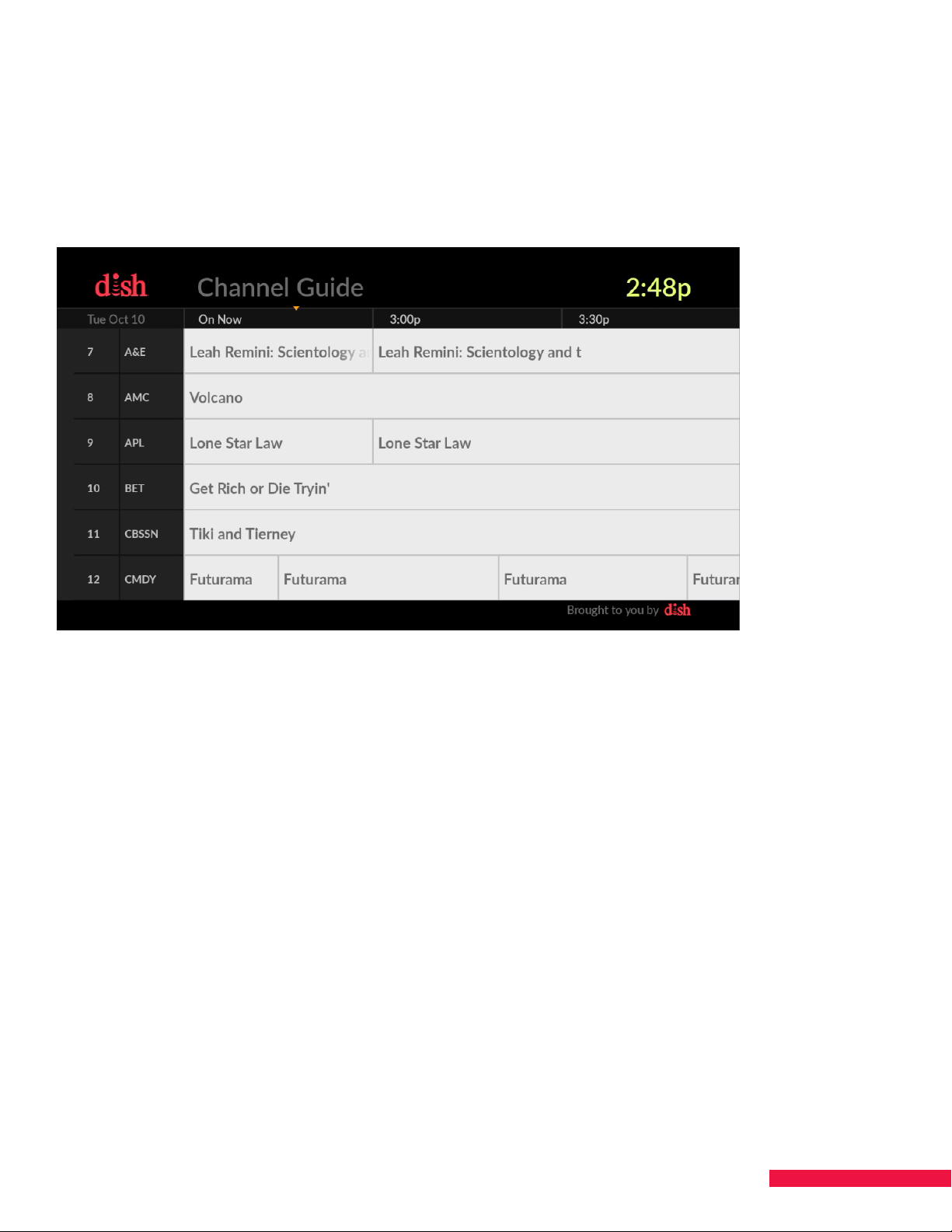
CHAPTER 12 SET UP A PROGRAM GUIDE
The Program Guide is a scrolling or stepped guide that includes a list of services and programs available to
viewers (See Figure 20.).
When using EVOLVE, the Program Guide service does not need to be a configured to support the interactive Program Guide.
However, the guide data download needs to be configured to update daily.
Figure 20. DISH Program Guide
Configure Program Guide Output Options
The options for managing the Program Guide are located on the Services page, where the Program Guide
appears as a Source, like other services. The Program Guide can be assigned to one output or multiple outputs,
like any other service.
From the Services page:
1. Click the down-arrow under Details to the right of Program Guide (See Figure 21.).
2. Select an output type—QAM, IP, or NTSC.
3. Enter the Output number. Output - QAM Channel = 2 to 158; sub-channel = 1 to 99; i.e., 10-1, no more than
24 sub-channels per QAM channel; IP Stream = Desired IP/Port (e.g., 224.0.0.1:7000).
4. Select a Scrolling option. Continuous will continuously scroll through the services listed in the guide.
Stepped will show six lines at a time then move on to the next six and will cycle through all services.
5. Click Apply.
NOTES:
• When configuring services for the Program Guide, enter information into the Virtual Channel Number box or
the channel will be excluded from the scrolling Program Guide.
• The Program Guide is only available in MPEG-4 format when output digitally; it does not support MPEG-2.
• Services assigned the lowest priority numbers will be interrupted during daily Program Guide update if no
tuners are available.
43
Page 44
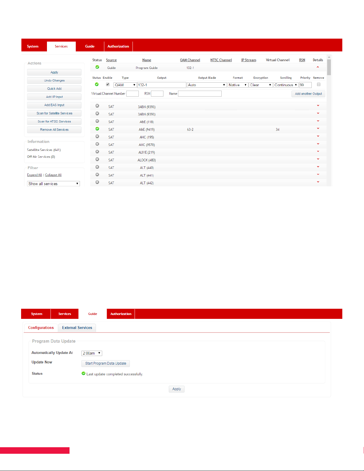
Figure 21. Guide Output Options
Configure Update Time for the Program Guide
The Program Guide’s channel information can be updated immediately after adding new information and should
be set to update on a daily basis in the Guide page (See Figure 22.).
• Click Start Program Data Update for an immediate update
• Select a time from the drop-down box for the Program Guide to be automatically updated each day.
Click Apply to confirm the time.
Figure 22. Program Guide - Data Update
44
Page 45
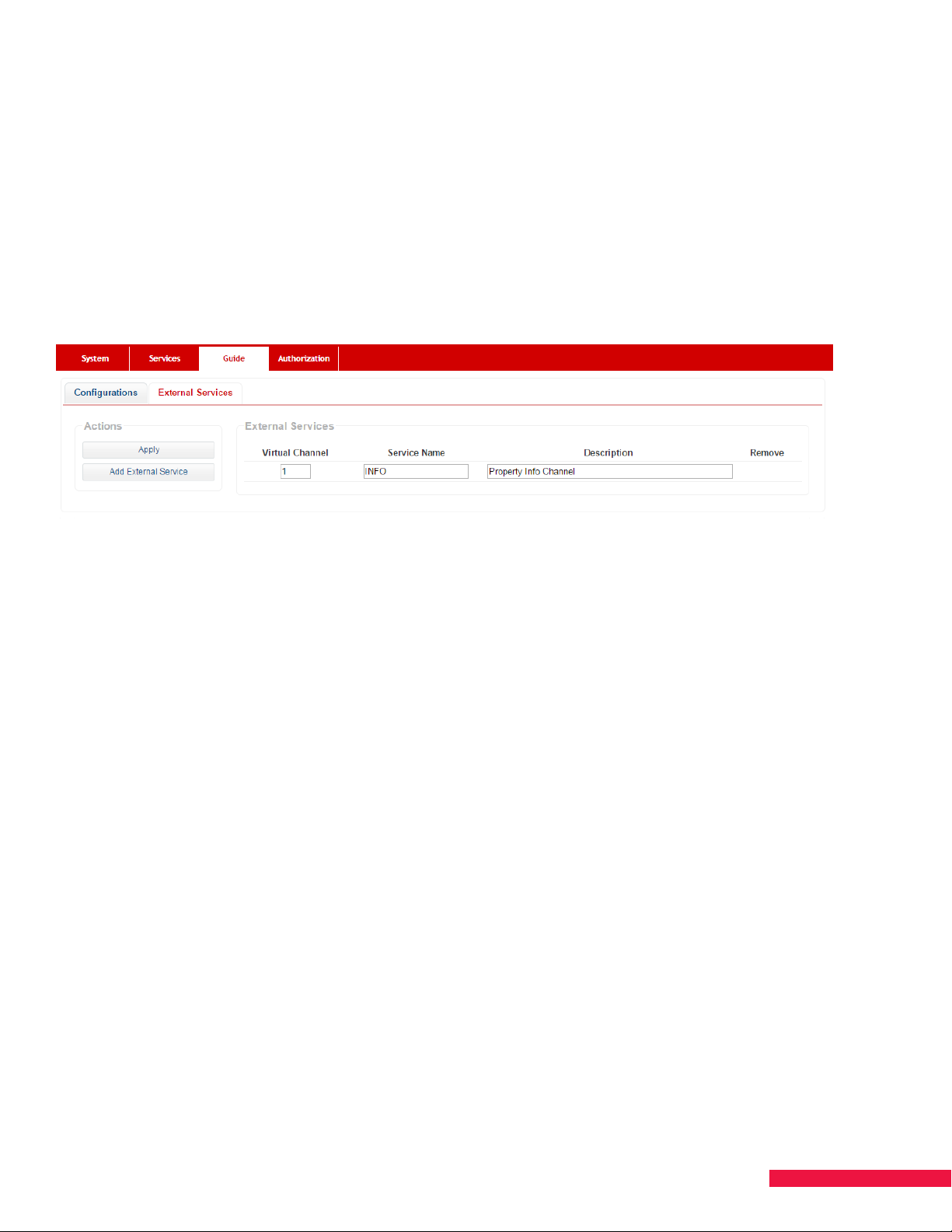
Adding External Services to the Program Guide
When there are non-SMARTBOX services distributed on the plant, you can have the channel and a brief
description appear in the Program Guide.
1. Go to the External Services tab of the Guide page (See Figure 23.).
2. Click the Add External Service button.
3. Enter in the Virtual Channel, Service Name, and Description then click Apply.
Figure 23. External Services
45
Page 46

CHAPTER 13 EVOLVE CONFIGURATION
EVOLVE is an Android TV™ powered set-back box that seamlessly integrates streaming apps, live linear
programming and casting into one customizable solution for the hospitality industry. EVOLVE oers guests a more
intuitive way to engage with content from their mobile devices using their room’s TV. Please refer to the EVOLVE
User Manual and EVOLVE Installation Manual for more detailed information and setup instructions of EVOLVE.
EVOLVE functionality requires 1.1 Satellite Receiver Blades that need to be authorized for EVOLVE as well as DRM
Pro:Idiom, Output QAM, and/or Output IP.
You will need to authorize your SMARTBOX for EVOLVE as well as DRM Pro:Idiom, Output QAM, and/or Output
IP. Once authorized for EVOLVE, you will see a new page titled EVO LVE between the Guide and Authorization
pages (See Figure 24.). Please refer to Chapter 6 AUTHORIZE SMARTBOX for details on how to authorize your
system.
You will need to configure SMARTBOX by going through the standard process. Once the satellite feeds,
authorizations, and services configurations have been applied, you can proceed to the EVOLVE page. The
EVOLVE page is used to load all files for EVOLVE functionality and set zone-channel access.
NOTES:
• When configuring QAM services for EVOLVE, do not use QAM channels 2-6. EVOLVE will not receive or
display those services. EVOLVE reserves those for use with DOCSIS.
• It is not advised to enter any text in the “Name” field when configuring services for use with EVOLVE.
It will prevent EVOLVE from displaying the channel logo in the guide.
Figure 24. The EVOLVE Page
46
Page 47
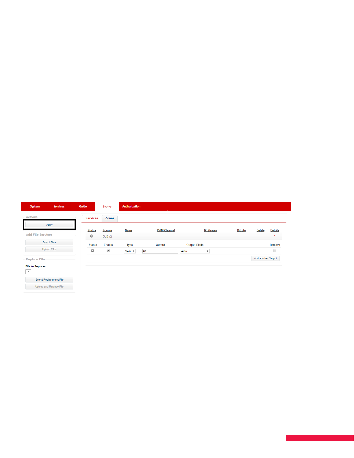
Set Up the DVB-SI Service
The DVB-SI is a stream of data output from SMARTBOX which contain tables of information necessary for EVOLVE
to be provisioned, recognize channel lineup changes, side-load applications, and take software updates. It must
be configured for the EVOLVE units to function. Take note of the output assigned to the DVB-SI service. This will
be entered into EVOLVE units during installation.
NOTE: Unlike the files discussed in Adding Additional Files, no bitrate setting is required for DVB-SI
1. Go to the Services tab on the E VO LVE section
2. You will see the only pre-listed service is the DVB-SI
3. Click the Details arrow to configure the service, then click the Add another Output button
4. Select the Ty p e depending on if the installation will be QAM or IP
5. Enter the Output channel. EVOLVE is pre-configured with the default QAM carrier for the DVB-SI as 98 and
default multicast address for IP as 239.100.10.1:36000; however, any unused QAM carrier 5 to 158 and any
unused, valid multicast address can be configured
6. If outputting content via QAM, select the Output Blade or leave on “Auto” depending on your blade
configuration and channel map
7. Click Apply on the upper-left side of the screen to save the configuration (See Figure 25.).
Figure 25 EVOLVE - Apply button with DVB-SI set for Default QAM
Adding Additional Files
In addition to the DVB-SI, EVOLVE requires additional files to function properly and to be customized based on
property preferences. These files include the provisioning, EVOLVE software, EPG logos, and App APKs and must
all be .ts files to be loaded and configured. Take the following steps for each individual file that needs to be
uploaded.
1. Click the Select Files button under the Add File Services section.
2. Navigate to the location where you saved the file on your computer and select the desired file. Note, the
.ts files should have been downloaded from the Configuration tool (refer to EVOLVE Installation Manual for
more information).
3. Once selected, click the Upload Files button.
4. Once SMARTBOX finishes uploading, it instructs you to refresh. Click the Refresh now button to see the
uploaded file listed as an available service to configure (See Figure 26.).
47
Page 48
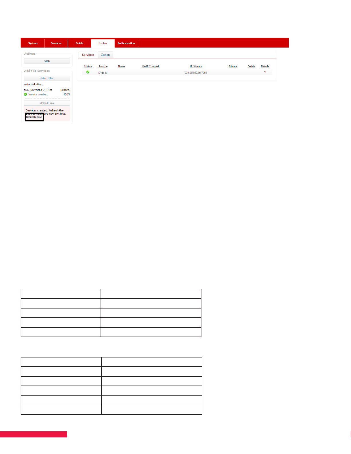
Figure 26 EVOLVE - Refresh now button when adding a service
5. Click the Details arrow of the file to configure the service, then click the Add another Output button
6. Select the Type
NOTE: On QAM systems, the files can only be assigned to the same QAM carrier as the DVB-SI. On IP systems,
separate multicast addresses will need to be configured for each service. The multicast address must be dierent
for each service, while the ports can be the same or dierent for every service depending on the network
configuration. This applies to both the provisioning files and content streams.
7. Enter in the Output (for IP only)
8. Configure the bitrate for the service and click Apply
NOTE: The bitrate determines how quickly the data from the file is sent out to the EVOLVE units. The combined
bitrates of all the EVOLVE provisioning services cannot exceed 20,000 Kbps regardless of output type. It is
recommended that larger files such as EVOLVE software or App APKs be assigned higher bitrates. The bitrates
can be reconfigured as needed depending on the current files being output.
EVOLVE-Bitrate Example 1
File Type Bitrate
Provisioning File 1000 Kbps
EPG Logos 1000Kbps
App APK 6000Kbps
EVOLVE Software 12000 Kbps
EVOLVE-Bitrate Example 2
File Type Bitrate
Provisioning File 1000 Kbps
EPG Logos 1000 Kbps
App APK 1 4000 Kbps
App APK 2 4000 Kbps
EVOLVE Software 10000 Kbps
48
Page 49
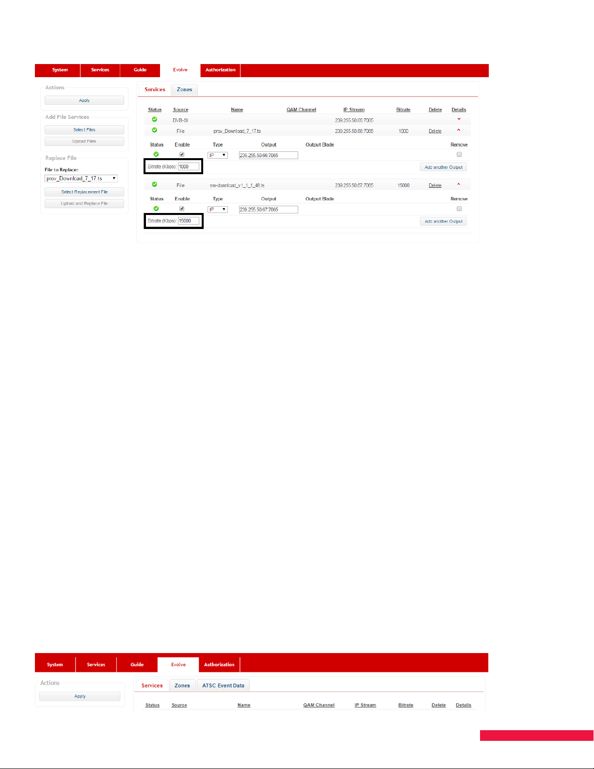
Figure 27 EVOLVE - Bitrate Configuration -IP Output
Replacing Existing Files
If you need to change the files being sent to the EVOLVE units, for example to update the software version being
broadcast, perform the following steps.
1. Under File to Replace in the Replace File section, select the specific file that you wish to replace in the
drop-down menu
2. Click the Select Replacement File button
3. Locate and select the replacement file from where it is stored on your computer.
4. Click the Upload and Replace File button.
5. Click the Refresh now button to see the replacement file listed as a service. The new file will retain the same
configuration as the service it replaced.
Set Up ATSC for EVOLVE
ATSC functionality on EVOLVE is supported in SMARTBOX software 0.2.16 or newer. You will need to scan for and
configure your ATSC services as normal (see Chapters 9 and 11). This allows ATSC locals to display on EVOLVE.
However, the SMARTBOX is not able to pull guide data from the ATSC signal. It will pull guide data from the
corresponding satellite local channel and send that to EVOLVE.
You need to tell the SMARTBOX which satellite channel corresponds to each configured ATSC service. To do this,
once you’ve scanned for and configured the ATSC services, navigate to the EVOLVE tab (See Figure 28.). Then
select the ATSC Event Data tab (See Figure 29.). The ATSC services you’ve configured are shown with no satellite
event data yet set.
Figure 28
49
Page 50
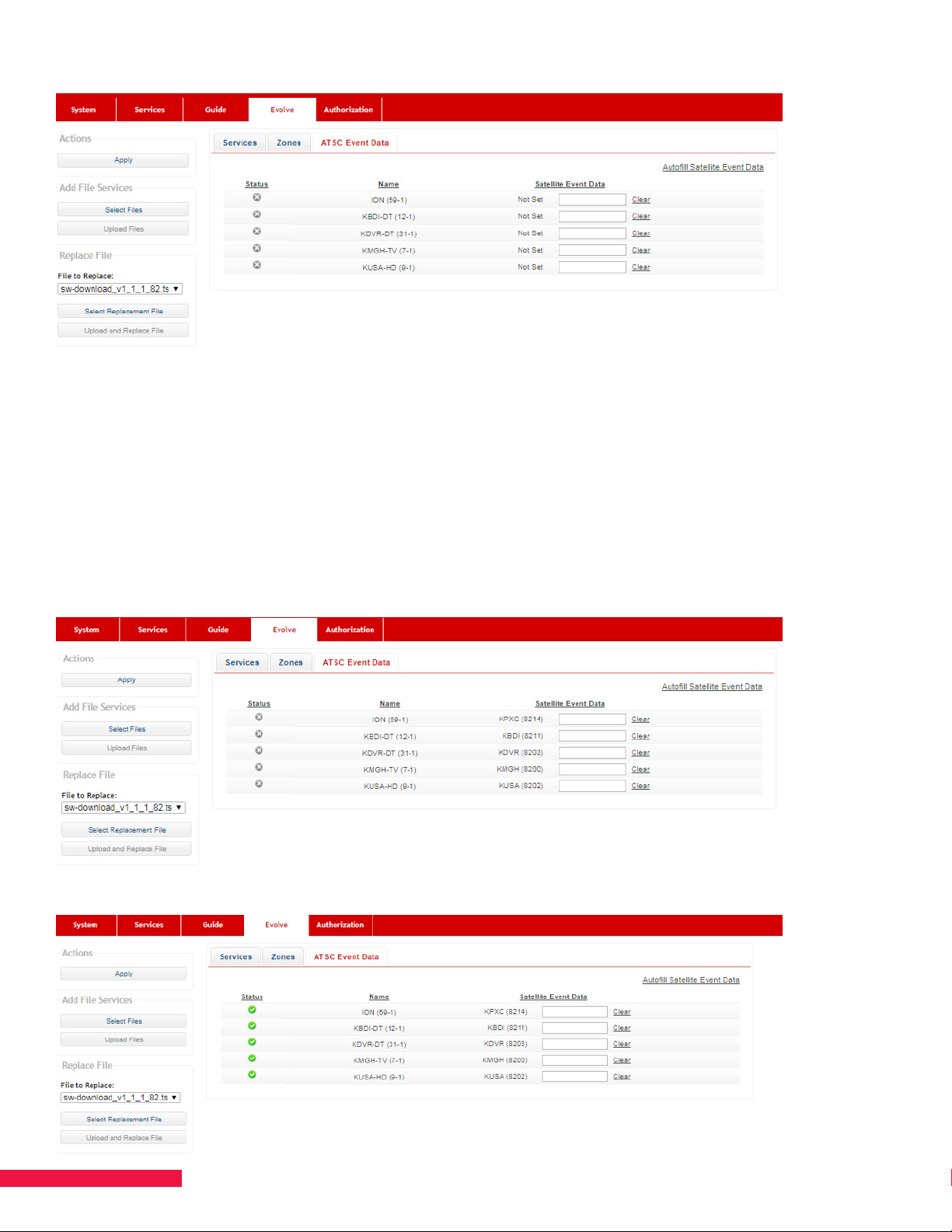
Figure 29
You can either set each corresponding satellite channel automatically or manually.
Automatic Process
Select the “Autofill Satellite Event Data” option in the top right corner. The SMARTBOX will list under the Satellite
Event Data section the correlating satellite channel to each ATSC channel (See Figure 30.). Finally, hit “Apply”.
This ocially binds each channel for guide purposes. You’ll see the status icon change to green once complete
(See Figure 31.). Once this step is complete, you’ll need to run a manual guide scan (Chapter 11) to update the
database being sent to EVOLVE to include the new channels.
Figure 30
Figure 31
50
Page 51
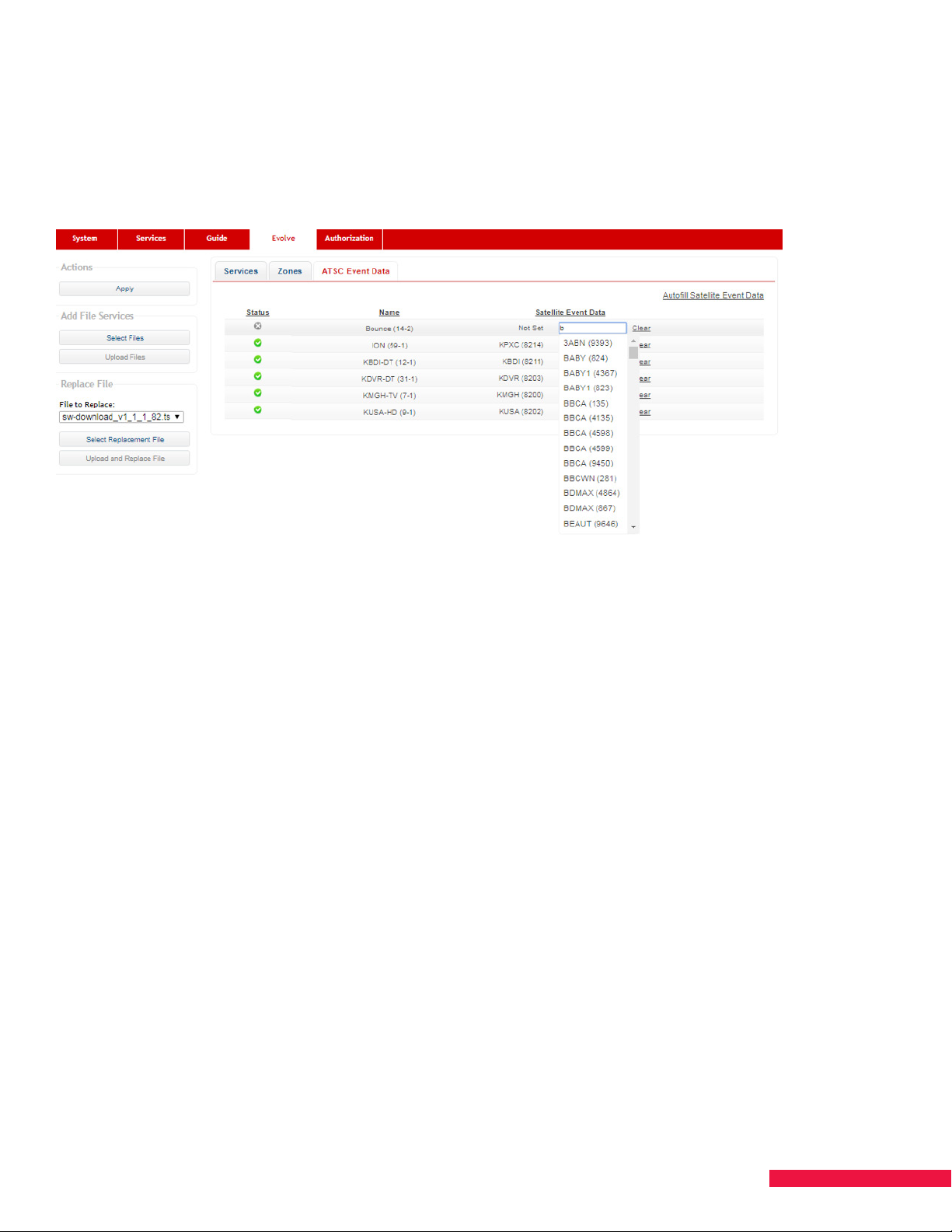
Manual Process
To manually correlate the ATSC-satellite services, begin typing the satellite channel name in the empty field to the
right of the ATSC service. As you type, a drop-down will appear listing available options (See Figure 32.). Select
the appropriate channel and apply. Once this step is complete, you’ll need to run a manual guide scan (Chapter 11)
to update the database being sent to EVOLVE to include the new channels.
Figure 32
NOTE: There are more local services available o-air than satellite. Thus, not all ATSC services will have guide
data from a corresponding satellite service to pull guide data from. You can activate these services but EVOLVE
will display “No Information” in the guide for such services.
Set Zones for Services
To comply with DISH Business Rules and possibly property brand guidelines, you may need to restrict some
services to certain zones. For example, premium services cannot be shown in the lobby. Please refer to EVOLV E
Installation Guide for more information on setting up zones within EVOLVE units.
1. Configure content services according to your channel map on the Services page per the instructions in
Chapter 11 MAP SERVICES
2. Once all services are configured, go to the Zones tab on the E VO LVE page
3. You will see all the configured services listed alphabetically and the possible 8 zones across the top regardless
of how many zones you have set up within the EVOLVE units. Any unused zone within EVOLVE units can be left
unchanged as it will have no impact on the SMARTBOX output
4. Disable individual services by unchecking the checkbox under the desired zone or clicking the None button
5. Disable all services for a zone by clicking the checkbox under the zone identifier. A zone that has a horizontal
line instead of a check mark in the box has at least one service disabled and one service active in that zone
6. Individual services can be enabled by clicking empty checkboxes or clicking the All button
7. Enable all services for a zone by clicking empty checkboxes or checkboxes with horizontal lines
8. Click the Apply button to save any changes
NOTE: Always check the Zones tab when adding new services to confirm they are assigned to the correct zones.
EVOLVE units will automatically process any applied changes.
51
Page 52
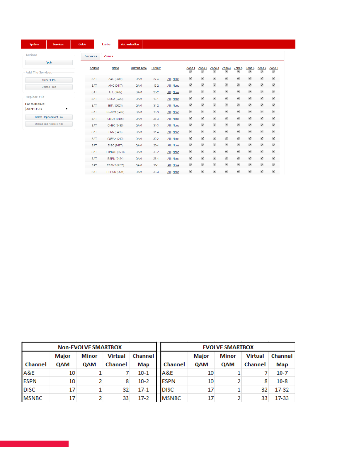
Figure 33 EVOLVE - Zones Tab
NOTE – Nuances to Feeding Video to Non-EVOLVE Devices
A SMARTBOX authorized and configured for EVOLVE may also be used to feed signal to non-EVOLVE devices
(e.g., TVs, treadmills, etc.) at the same property. When doing this, there are two nuances to be aware of.
1) For both QAM and IP systems, if you would like the traditional Program or “Scrolling” Guide to be displayed on
non-EVOLVE devices, you will need to configure it as a service per usual (see Chapter 12). Note, EVOLVE units
ignore the Program Guide service but continue display the interactive guide.
2) You’ll still need to create the channel map file to load into the TV (e.g., the TLX file for LG TVs) as you’ve done
for encrypted QAM/IP video systems previously. However, for QAM systems, when the SMARTBOX is authorized
for EVOLVE functionality, this changes how the QAM channels output and will impact how you should setup the
mapping file. In the SMARTBOX, you’ll still need to assign each channel with a major and minor channel (e.g.,
10-1, 10-2, 11-1, etc.) and a virtual channel (e.g., 1, 2, 15, 16, etc.). The dierence is that the SMARTBOX will now
output each service using only the major channel and virtual number. Thus, from the TV’s perspective, the virtual
channel becomes the minor channel. See Figure 34 which compares the channel mapping.
Figure 34
52
Page 53

DISH QAM OPERATIONAL MODE
CHAPTER 14 DISH QAM
You will need to authorize your SMARTBOX for both DRM Digital Upgrade as well as Output QAM. Once
authorized for DRM Digital Upgrade, you will no longer be able to have visibility to the Services page, nor will you
be able to output any bulk service.
Set Up DISH QAM
1. Go to the Configurations tab on the DISH QAM section (See Figure 35.).
2. Depending on the satellites installed, the default transponders for either Eastern Arc or Western Arc will be
pre-selected.
3. Select transponders for locals and/or international channels.
4. Enter Frequency Range (This will be the center frequency of the lowest and highest QAM channel). If
multiple ranges are required, enter the multiple ranges separated by a comma.
NOTES:
• The Frequency Range used must be between 57 MHz and 861 MHz.
• Maximum total frequency bandwidth used must be less than 768 MHz.
5. Select appropriate output blade.
6. Select either Adjacent or Non-Adjacent from High Bandwidth Channel Assignment.
• Adjacent – When this is selected, the system will attempt to alternate between low and high bandwidth
channels. When it is no longer able to do so, it will place high bandwidth channels next to each other.
• Non-Adjacent – When this is selected, the system will initially alternate low and high bandwidth channels,
and then place the remaining high bandwidth channels in non-adjacent carriers.
7. Select to whether to allow Higher Transponder Rates for outputting high bit-rate Spot Beam transponders.
8. When an ATSC blade is in the system, click the Scan for ATSC Services button. Once the scan is complete,
the visible ATSC services will be available to be selected for output.
9. For transponders modulated externally from SMARTBOX, enter the modulation information so that it can be
included in the DISH QAM Table (DQT) used by certain DISH receivers.
10. Select Apply Configuration.
11. Reset SMARTBOX.
NOTE: Any changes to a configuration running DISH QAM will require SMARTBOX to be reset to take the
changes.
53
Page 54
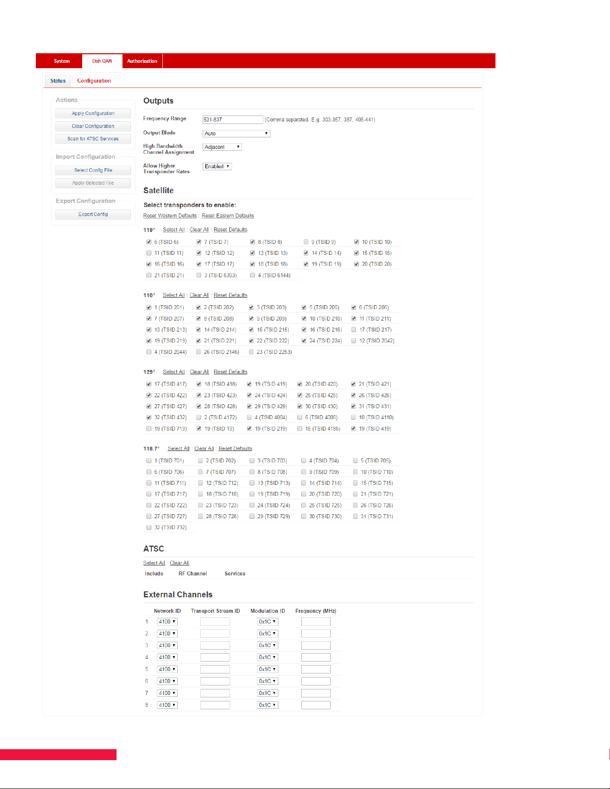
Figure 35. DISH QAM Configuration Tab
54
Page 55
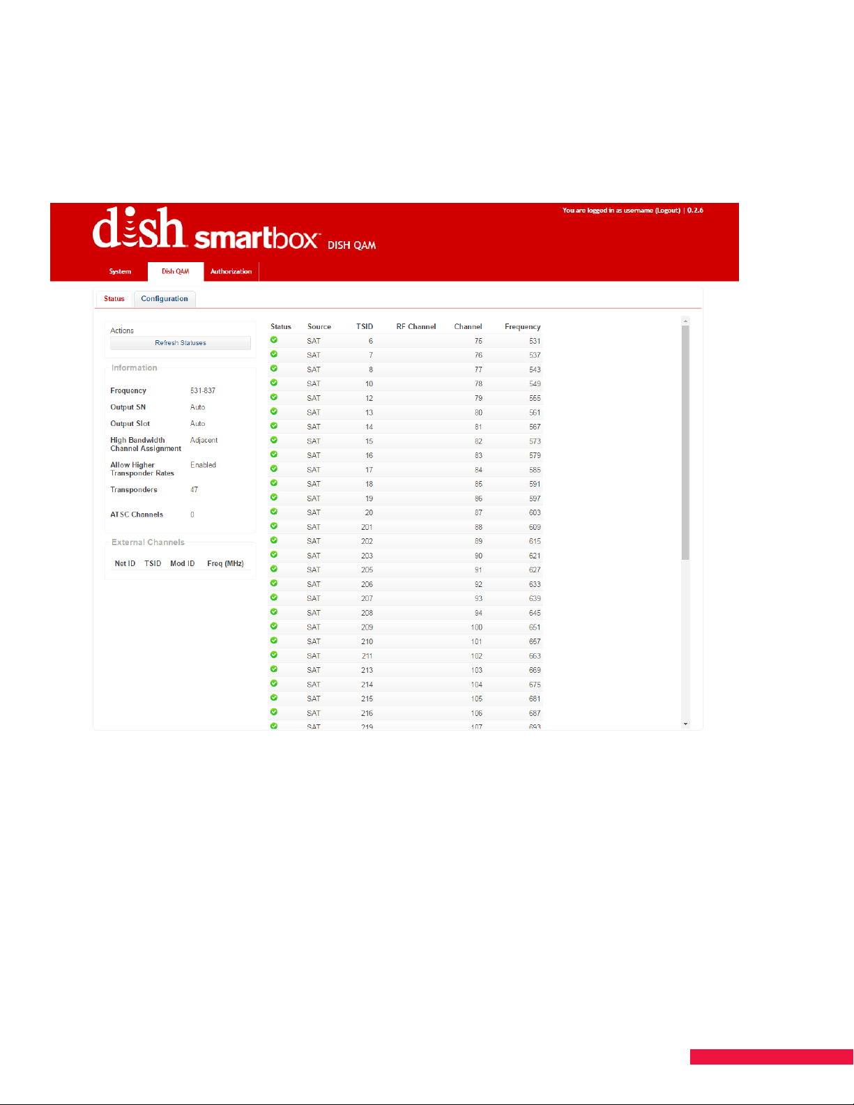
Validate DISH QAM Status
1. Go to the Status tab on the DISH QAM page (See Figure 36.).
2. You will be able to see the status for all services set up. Hover over the Status icon for additional information.
3. Status does not auto-update once loaded. To update, press the Refresh Statuses button.
Figure 36. DISH QAM Status Tab
55
Page 56

CHAPTER 15 MANUAL FACTORY DEFAULT
If at any point you lose the ability or documentation to access the SMARTBOX user interface, there are steps
to take the SMARTBOX manually through a factory reset. Only follow these steps if ABSOLUTELY necessary.
Factory Default Without Access to User Interface
Performing this will remove all user settings from the system and return to factory defaults.
1. Remove power from the system
2. Remove all blades from the system
3. Place one blade into slot 16
4. Power system up
5. Wait to see all 4 satellite input LEDs flashing green
6. While the satellite input LEDs are flashing green, remove the blade from slot 16
7. The satellite input LEDs will begin to flash red
8. The regular booting process will now start
9. You may reinsert blades into system for use
56
Page 57

CHAPTER 16 SOAK TEST AND PREPARE TO SHIP
Soak Test
Once SMARTBOX has been assembled, allow it to run 24 to 48 hours. At the end of the run, perform a
functional test to ensure all components are working as they should be.
Prepare to Ship
Once the soak test has been completed, the unit is ready to be disassembled and packed for shipping to the
customer site.
1. Unplug power sources, LNBF cables and data cables. Package the cables to include in the shipping box.
2. Remove power supplies from the chassis.
CAUTION: Power supplies must be shipped outside the chassis. Leaving them in the chassis could damage the
power supplies or backplane.
3. Remove antenna from SMA connector; wrap it securely.
4. Pack the chassis in original box.
5. Add cables, power supplies, cellular antenna and other accessories to the box. Close the box and tape
it securely.
57
Page 58
CHAPTER 17 INSTALL ON CUSTOMER SITE
The following table includes a high-level “punch list” of tasks, actions, and references to assist you in setting up
SMARTBOX on a customer site. The instructions are very similar to an initial installation. The list assumes that
software was updated during testing on the integration site and is up to date. However, the software version
should be checked to ensure that it is the latest version.
TASK ACTION REFERENCE
Unpack and
reassemble SMARTBOX
and connections.
Establish connection. Set up TCP/IP connection and login.
Refresh satellite feeds.
Verify tuners lock.
Scan for spot beams
and satellite services.
Set up CAS Server
(if needed).
Follow guidelines for installation.
Chassis tab
L-Band Inputs.
Blades tab
for each blade.
Chassis tab
then Scan for Satellite Services.
Admin tab
Click Apply button under
Verify tuners have locked
Start Spot Beam Scan,
CAS Server.
CHAPTER 2 ASSEMBLE
CHASSIS, POWER SUPPLIES
AND POWER INSERTERS
CHAPTER 4 UPDATE
SOFTWARE:
ESTABLISH COMMUNICATION
CHAPTER 4 UPDATE
SOFTWARE:
ENABLE SATELLITE INPUTS
CHAPTER 4 UPDATE
SOFTWARE:
VERIFY TUNERS LOCK
CHAPTER 7 SCAN FOR SPOT
BEAMS AND SATELLITE
SERVICES
CHAPTER 10 SET UP CAS
SERVER
Scan for ATSC services
(if needed).
Configure or add new
services or channels.
Services page
ATSC Services.
Services page – various options. CHAPTER 11 MAP SERVICES
Scan for
CHAPTER 11 MAP SERVICES
58
Page 59
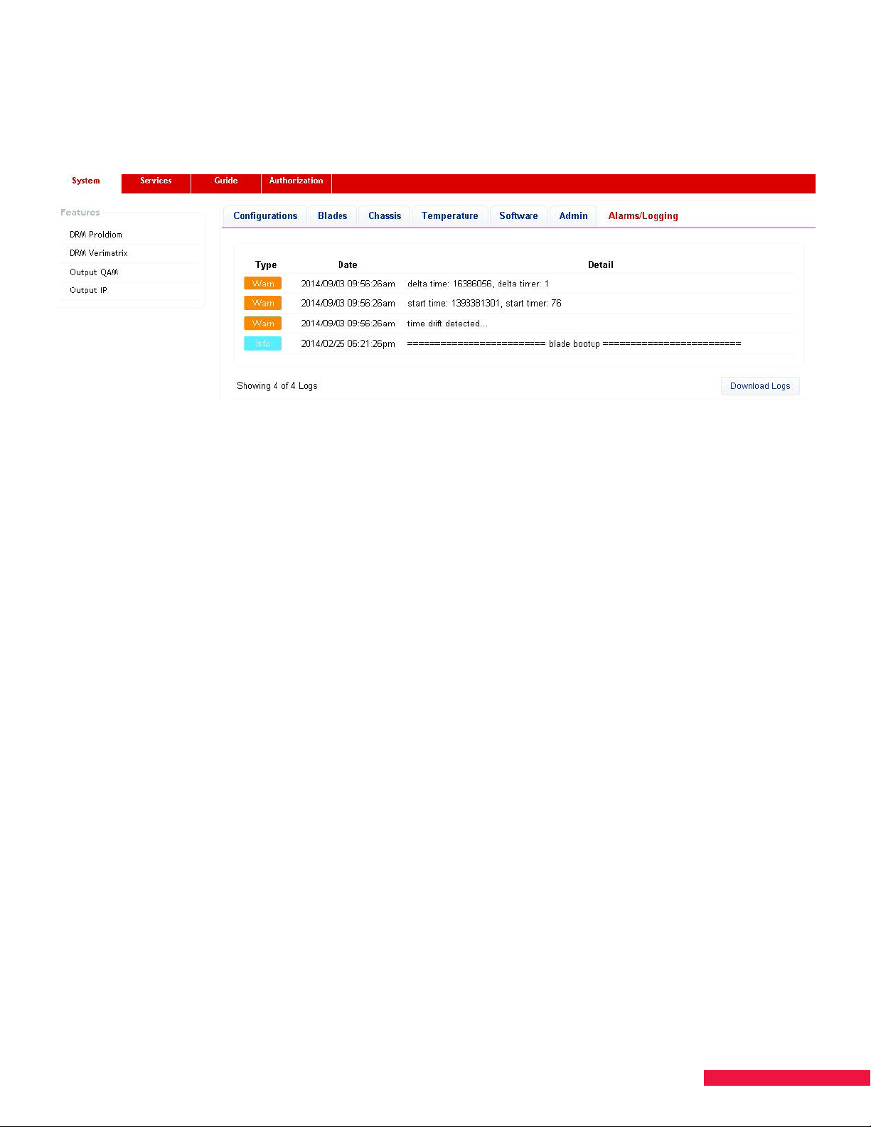
CHAPTER 18 STATUS, WARNINGS, AND FAULTS
Log history data is provided on the Alarms/Logging tab found on the System page. The Download Logs button
creates a .txt file containing logged events (See Figure 37.).
Figure 37. Alarms/Logging
SMARTBOX alarm messages are triggered by the following events:
• A feature has been added/removed
• A blade has been removed or a blade has reset
• A change in service descrambling status has occurred
• Tuner(s) lost lock (slot number and tuner number)
• Over-temperature warning/fault occurs
• Fan fault (including fan number) occurs
• Transcoder module chip failure or reset
• NTSC chip reset
• More than 100 CERs occur within a minute (number of CERs, service, slot number, and tuner number)
• Non-service impacting internal system processes
59
Page 60
CHAPTER 19 DIAGNOSTIC INFORMATION
ATSC Receiver Blades
If an ATSC channel is not coming through, check the diagnostic information for the ATSC blade.
1. Click the Blades tab.
2. Locate the ATSC card and click the down-arrow under Details.
3. Verify the following:
RSSI – Received Signal Strength Indicator
Low RSSI indicates the antenna is not tuned correctly. In the event of a low RSSI, SMARTBOX may not
be able to lock to a service. -75 is the lowest value for which the software will assign a service to a tuner.
Tuner Lock and Demod Lock
Both Tuner and Demod must be locked to receive data from a station.
Demod SNR–Demod Signal-to-Noise Ratio
This value indicates a signal-to-noise ratio for the individual tuner. Higher is better. Above 20 is good.
RS Uncorrected– Reed-Solomon Errors
When the signal is weak, there may be a lot of RS errors. Each error causes a drop of at least one packet of
data and usually results in deteriorated picture or sound. Zero is good; more than a few errors indicates a problem.
ATSC Receiver Blade Input Specifications
ATSC Receiver Blade Input Power Range
The signal input into the ATSC Receiver Blade should fall into the range below. Any signal power outside of this
range may result in intermittent performance. Be sure to note the measurement being used.
Component
dBm dBmV
High -9.5 dBm +39.25 dBmV
Low -83.5 dBm -34.75 dBmV
ATSC Receiver Blade Signal Quality
1) Services with an SNR less than 20 for an incoming ATSC signal is likely to have some RS uncorrected errors,
which indicate that issues such as pixelation, freezing, or dropped services may occur.
2) If the RSSI is less than -75 during the scan, the services on that RF channel will not be listed as configurable
services. The RF channel will also not be listed if there are too many RS Uncorrected errors. As the scan is only a
few seconds per channel, there should be zero RS Uncorrected errors. The lower the SNR the more the number of
RS Uncorrected Errors there will be.
Satellite Receiver Blades
CER – Character Error Rate
A high CER number (in the thousands) indicates there is a problem with the satellite stream coming into
SMARTBOX - check the satellite feeds. A small number is not a problem. An increasing number indicates a current
signal issue. You can reset the CER counter on the satellite receiver blades by clicking the Reset all CER Counters
on the Blades tab to verify if the counter is increasing. This will bring the counters back to 0. If a tuner loses lock,
the CER will be reset.
SNR – Signal to Noise Ratio
A high SNR is a good indication. For satellite receiver blades, an SNR greater than 12 is desirable.
60
Page 61

CHAPTER 20 LED INFORMATION
LED Definitions for Satellite Feeds
Satellite Input LED Indicators:
GREEN = Signal power is detected on the LNB.
AMBER = High power is detected on the LNB.
RED = Low or no signal power is detected on the LNB.
LED Definitions for Blades
Enable LED: Stays lit solid green for the entirety of the time the blade is powered on and is a part of the
authorization donut.
Tx/Rx LED: On initialization/reset/reboot this LED is OFF. When synchronization is initiated successfully by a
blade with the backplane, this LED will begin flashing. Backplane synchronization will be continuously
monitored,
and if at any point synchronization fails, the LED will change from flashing green to OFF until synchronization
begins again successfully.
QAM Output LED: If any service is assigned to any QAM on this blade, the output LED will be solid green. If no
services are assigned to any QAM on this blade, the output LED will be o.
NTSC Output LED: If any service is assigned to any NTSC channel on this blade, the output LED will be solid
green. If no services are assigned to any NTSC channel on this blade, the output LED will be o.
Satellite Receiver Tuner LED:
GREEN = Lock has been achieved on all tuners that have been attempted to be tuned.
AMBER = Lock has failed on at least one tuner that has been attempted to be tuned.
RED = Lock has failed on all tuners that have been attempted to be tuned.
OFF = No tuners have attempted to be tuned.
ATSC Receiver Tuner LED:
GREEN = Lock has been achieved on all tuners that have been attempted to be tuned.
AMBER = Lock has failed on at least one tuner that has been attempted to be tuned.
RED = Lock has failed on all tuners that have been attempted to be tuned.
OFF = No tuners have attempted to be tuned (i.e., no ATSC services have been assigned to an output).
LED Definitions for Cellular Antennas
Cellular Modem LED Indicator:
GREEN = Signal power is detected on the antenna.
AMBER = Low signal at antenna input.
RED = No signal detected.
OFF = Not used.
61
Page 62

CHAPTER 21 NTSC CHANNELFREQUENCY
The NTSC blade supports 24 channels. These channels must have contiguous frequencies. For example, channels
7-13 are higher in frequency than 14-22. If you start at channel 10, there will be a frequency hole and the blade will
not support the full number of channels.
CHANNEL
14 121.25 43 337.25
15 127.25 44 343.25
16 133.25 45 349.25
17 139.25 46 355.25
18 145.25 47 361.25
19 151.25 48 367.25
20 157.25 49 373.25
21 163.25 50 379.25
22 169.25 51 385.25
7 175.25 52 391.25
8 181.25 53 397.25
9 187.25 54 403.25
10 193.25 55 409.25
11 199.25 56 415.25
12 205.25 57 421.25
13 211.25 58 427.25
23 217.25 59 433.25
24 223.25 60 439.25
25 229.25 61 445.25
26 235.25 62 451.25
27 241.25 63 457.25
28 247.25 64 463.25
29 253.25 65 469.25
30 259.25 66 475.25
31 265.25 67 481.25
32 271.25 68 487.25
33 277.25 69 493.25
34 283.25 70 499.25
35 289.25 71 505.25
36 295.25 72 511.25
37 301.25 73 517.25
38 307.25 74 523.25
39 313.25 75 529.25
40 319.25 76 535.25
41 325.25 77 541.25
42 331.25 78 547.25
VIDEO CARRIER
FREQUENCY FOR CATV
CHANNEL
VIDEO CARRIER
FREQUENCY FOR CATV
62
Page 63

CHAPTER 22 HARDWARE COMPONENTS
16-Slot Chassis
Each chassis can hold up to 16 blades. The chassis comes equipped with two hot-swappable power supplies, a
power supply filler plate and a cellular modem for communication back to DISH.
8-Channel Satellite Receiver Blade
Each satellite receiver blade provides eight channels of satellite TV service via eight discrete tuners. Each blade
has either two ProCAM 1.0s with two SmartCards or a single ProCAM 2.0 with an embedded chip and that are
authorized in the same manner as a residential DISH receiver.
8-Channel Satellite Receiver Blade with Transcoder Module
Each transcoder module is a daughter card that comes pre-mounted on a satellite receiver blade. If there is
a transcoder module on one satellite receiver blade in a system, they must all have transcoder modules. The
transcoder module can be used to convert video content from Native to MPEG-2 for applications that have TVs that
support MPEG-2 video format but not Native.
8-Channel ATSC Receiver Blade
Each ATSC receiver blade provides up to eight SPTS from up to eight channels of digital, over-the-air (OTA) TV
service for use in QAM or IP outputs.
QAM 16 Blade
Each 16-carrier QAM blade outputs digital audio/video signals for distribution via standard CATV (5-1000 MHz)
coax infrastructure. A maximum of 64 bulk MPEG-4 HD channels are supported. DRM encoding may be added as
needed.
QAM 48 Blade
Each 48-carrier QAM blade outputs digital audio/video signals for distribution via standard CATV (5-1000 MHz)
coax infrastructure. A maximum of 96 bulk MPEG-2 or MPEG-4 HD channels are supported. DRM encoding may be
added as needed.
QAM 96 Blade
Each 96-carrier QAM blade outputs digital audio/video signals for distribution of DISH QAM via standard CATV (51000 MHz) coax infrastructure. Format is QAM256, not QAM1024. DRM Digital Upgrade must be used for this blade.
24-Channel Analog NTSC TV Blade
Each 24-channel analog NTSC blade supports analog output of audio/video signals that can be used with all analog
capable TVs. A maximum of 72 channels per chassis with 24 channels per blade is supported.
Power Supply
Each power supply is hot-swappable once unplugged. Two power supplies are included with each chassis
—the power supplies are load balancing. An additional slot is available for additional redundancy or high-power
SMARTBOX installations.
Chassis Spare Fan Assembly
A spare fan assembly used to replace the original chassis fan in case one fails.
Single Blade Filler Plates
Single blade filler plates are provided to cover unused slots in the SMARTBOX chassis; filler plates facilitate air-flow
through the chassis to help prevent over-heating. All slots need to contain either a blade or a filler plate.
Power Supply Filler Plate
One power supply filler plate is included with each chassis. The power supply filler plate is used to cover an unused
power supply slot in the chassis.
63
Page 64
CHAPTER 23 TECHNICAL SPECIFICATIONS
Power Consumption
The SMARTBOX chassis allows for up to three power supplies to be installed. The power supplies are load-
sharing and provide auto-sensing backup for a failed supply. Each power supply can deliver 600W over the entire
SMARTBOX operating temperature range. The total power consumption for blade configurations that support
typical applications is less than 600W, meaning two power supplies provide 1:1 redundancy. The estimated power
consumption for each blade is provided in the table below:
Power (Watts)
Chassis Assembly 90
Satellite Receiver Blade 30
ATSC Receiver Blade 20
Satellite Receiver Blade
with Transcoder Module
QAM16 Blade 25
QAM48 Blade 50
QAM96 Blade 50
NTSC Modulator Blade 70
NOTE: The actual power consumption of SMARTBOX will be roughly 10% greater due to normal power supply
ineciency and the operating temperature of SMARTBOX.
Example power consumption for FTG configuration with 16 QAM outputs and 40 services:
1 Chassis Assembly 1 x 90W = 90W
5 Satellite Receiver Blades (eight services each) 5 x 30W = 150W
1 QAM16 Blade 1 x 25W = 25W
Preliminary SMARTBOX DC power consumption 265W
10% additional power consumption (See Note) .1 X 265W= 27W
60
Actual Expected SMARTBOX DC power consumption 292W
The 600W maximum power delivery for each power supply is specified for the DC power the supply can deliver
to SMARTBOX. The power numbers in the table above are for DC power consumption.
64
Page 65
Chassis Assembly Specifications
Mechanical and Environmental
Dimensions (H x W x D) 8.7” x 17.6” x 15.8” (compatible with 19” EIA rack)
Weight
Line Voltage 90–264 VAC, 47–64 Hz
Power Consumption MAX 1200W
Operating Temperature 0–50°C (32–122°F), non-condensing.
Blade Options
Satellite Receiver Blade 1 to 12 Blades
ATSC Receiver Blade 0 to 3 Blades
QAM 16 Blade 0 to 3 Blades
QAM 48 Blade 0 to 2 Blades
QAM 96 Blade 0 to 2 Blades
NTSC Analog Blade 0 to 3 Blades
Satellite Inputs (from LNB)
Number of Inputs 4, labeled Sat 1 thru Sat 4
Connector F, female
17.0 lbs. Includes 2 power supplies, 1 power supply
cover, no filler plates, no blades
Impedance 75 ohms
Input Frequency L-Band, 950 – 2150 MHz
Input Power -25 to -65 dBm, aggregate
Return Loss > 15dB
Satellite Input LED Indicators
Number of LEDs 4, associated with each of 4 satellite inputs
Green Signal power is detected on LNB
Amber High signal on LNB
Red Low or no signal detected
Network Interfaces
Number of Inputs 4, labeled Data 1 through Data 4
Connections RJ-45, GbE, Full Duplex, Auto-Negotiate
Addressing Multicast
Transport Protocol UDP/IP
Transport Format SPTS
IP Management HTTP, TR-069
Local User Interface Web Browser
65
Page 66
SMARTBOX listens on the following layer 4 protocols:
HTTPS:
Server: hiawatha
Purpose: web application control
Port: TCP 443
SMARTBOX listens on the following layer 2 protocols:
ARP:
Server: linux
Purpose: address resolution
EtherType: 0x0806
LLDP:
Server: lldpd
Purpose: local system discovery
EtherType: 0x88cc
Typical configuration:
SMARTBOX is intended to be placed behind a firewall, and the device should be remotely accessed via VPN. This
prevents the possibility of brute force attacks, denial of service attacks, and other exploits that may end up leading
to service interruptions. SMARTBOX does use HTTPS as its primary configuration interface, so that passwords and
other trac sent to the device are transmitted over an encrypted link.
Cellular Modem Antenna Interface
Number of Connectors 1, labeled Cellular Antenna
Connector SMA, female
Impedance 50 ohms
Input Sensitivity -105 dBm typical
Transmit Power +24.5 dBm typical
Cellular Modem LED Indicator
Number of Indicators 1, labeled Cellular Antenna
Green Signal power is detected on antenna
Amber Low signal at antenna input
Red No signal detected
O Not used
Earth Ground Connection
Number of Grounds 1, labeled with Ground Symbol
66
Page 67
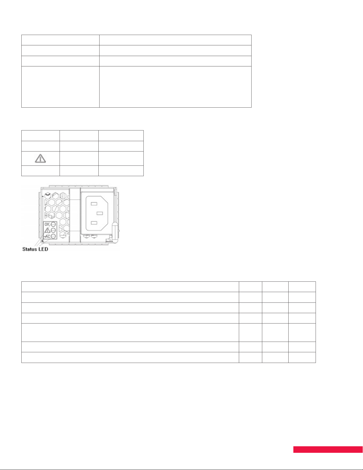
Power Supply Module
Input Voltage 90–264 Vac
Input Frequency 47–64 Hz
Maximum Input Current 9 AMPS
Special Features N + 1 Redundant
Hot swap
High eciency 91%@230 Vac, 50% load
Variable speed “smart fans”
600W delivered over 0 – 50°C
LED Indicator for Power Supply
LED Function Color
OK DC OK Green
Fail Yellow
~AC AC OK Green
LED Status
Conditions: Assumes two or more power supplies present and ON. DC Fail AC
No problems and power supply is on. On O On
Vo 12V Over current. On O On
AC input fail. O O O
Fan blocked or running under speed but outputs still within spec and not
over temperature. This is a Warning condition.
Over temperature and power supply has turned o. On O On
Fan below shutdown limit. On O On
On On O
67
Page 68

Satellite Receiver Blade
Dimensions (H x W x D) 7.5 x 0.9 x 14.5
Power Consumption 30W (Typical)
Satellite Channels 8 transponders and/or 8 programs
Modulation Rates DVB-S: Symbol Rates 1 to 45 MSps
Interleave 1/2, 2/3, 3/4, 5/6, 7/8
DVB-S2: Symbol Rates 5 to 33 MSps
QPSK Interleave 1/2, 3/5, 2/3, 3/4, 4/5, 5/6, 8/9, 9/10
8PSK Interleave 3/5, 2/3, 3/4, 5/6, 8/9, 9/10
Turbo FEC: Symbol Rates 2 to 30 MSps
QPSK Interleave 1/2, 2/3, 3/4, 5/6, 7/8
8PSK Interleave 2/3, 3/4, 4/5, 5/6, 8/9
Acquisition Range ± 5 MHz
Satellite Receiver Blade with Transcoder Module
Dimensions (H x W x D) 7.5 x 0.9 x 14.5
Power Consumption 60W (Typical)
Satellite Channels 8 transponders and/or 8 programs
Modulation Rates DVB-S: Symbol Rates 1 to 45 MSps
Interleave 1/2, 2/3, 3/4, 5/6, 7/8
DVB-S2: Symbol Rates 5 to 33 MSps
QPSK Interleave 1/2, 3/5, 2/3, 3/4, 4/5, 5/6, 8/9, 9/10
8PSK Interleave 3/5, 2/3, 3/4, 5/6, 8/9, 9/10
Turbo FEC: Symbol Rates 2 to 30 MSps
QPSK Interleave 1/2, 2/3, 3/4, 5/6, 7/8
8PSK Interleave 2/3, 3/4, 4/5, 5/6, 8/9
Acquisition Range ± 5 MHz
Conversions Supported MPEG-4 (Native) to MPEG-2 either HD or SD with no format conversion
ATSC Receiver Blade
Dimensions (H x W x D) 7.5 x 0.9 x 13.5
Power Consumption 20W (Typical)
Connector F-Female
ATSC Channels 8 carriers and/or 8 programs
Frequency Range 42–1002 MHz
Input Level per Carrier -35 to +44 dBmV
Return Loss >15 dB
Impedance 75 ohms
Optional Modules Transcoder
68
Page 69

QAM 16 Blade
Dimensions (H x W x D) 7.5 x 0.9 x 13.5
Power Consumption 25W (typical)
Connector F-Female
Output Frequency 54–1002 MHz
Channel Bandwidth 16 channels, 6 MHz per channel
Modulation ITU-T J.83B Annex B (256QAM), Inverse
QAM Symbol Rate 5.360537 MSps
Interleaving 128/1 Annex B
Channel Plans EIA, HRC, IRC, Manual
Output Frequency
Accuracy
Output Level 45 dBmV eective precombined output power
Output Attenuation 0 to 10 dB (0.5 dB step)
Output Level Flatness (54 to 864 MHz) ±1 dB
Spurious > 60 dBc (in 4MHz)
Output Impedance 75 ohms
Output Return Loss >11 dB
125 Hz
(864 to 1002 MHz) ±2 dB
QAM 48 Blade
Dimensions (H x W x D) 7.5 x 0.9 x 13.5
Power Consumption 50W (typical)
Connector F-Female
Output Frequency 54 to 1002 MHz
Channel Bandwidth 48 channels, 6 MHz per channel
Modulation ITU-T J.83B Annex B (256QAM), Inverse
QAM Symbol Rate 5.360537 MSps
Interleaving 128/1 Annex B
Channel Plans EIA, HRC, IRC, Manual
Output Frequency
Accuracy
Output Level 45 dBmV eective precombined output power
Output Attenuation 0 to 10 dB (0.5 dB step)
Output Level Flatness (54 to 864 MHz) ±1 dB
Spurious > 60 dBc (in 4MHz)
Output Impedance 75 ohms
Output Return Loss >11 dB
125 Hz
(864 to 1002 MHz) ±2 dB
69
Page 70

QAM 96 Blade
Dimensions (H x W x D) 7.5 x 0.9 x 13.5
Power Consumption 40W (typical)
Connector F-Female
Output Frequency 54 to 1002 MHz, 768 MHz channel range maximum
Channel Bandwidth 3.83, 5.48, 5.56, 5.67, 5.75, 6.43, 6.88, 7.71
Modulation ITU-T J.83B Annex A (64, 128, 256 QAM)
QAM Symbol Rate 3.33, 4.76, 4.84, 4.93, 5.00, 5.59, 5.98, 6.70 MSps
Interleaving 128/1 Annex B
Channel Plans EIA, HRC, IRC, Manual
Output Frequency
Accuracy
Output Level 45 dBmV eective precombined output power
Output Attenuation 0 to 10 dB (0.5 dB step)
Output Level Flatness (54 to 864 MHz) ±1 dB
Spurious > 60 dBc (in 4MHz)
Output Impedance 75 ohms
Output Return Loss >11 dB
125 Hz
(864 to 1002 MHz) ±2 dB
NTSC 24 Blade
Dimensions (H x W x D) 7.5 x 0.9 x 13.5
Power Consumption 50W (typical)
Connector F-Female
Maximum Number of NTSC
Channels
Frequency Range 120 to 552 MHz
Band Plan STD, IRC
24 NTSC RF with mono audio
Output Level 24 NTSC Channels 45 dBmV (min per channel)
Output Adjust Range 10 dB
Attenuation Steps Increment 0.5 dB
Output Impedance 75 ohms
Output Return Loss In-Band -11 dB 120 to 552 MHz
RF Flatness Response ±1 dB 120 to 552 MHz
Carrier Frequency Stability 5 kHz Std channel
Audio/Video Carrier Ratio 15 ±2 dB
70
Page 71

Tolerances and Ranges
Hardware
SNR
Demod SNR
RSSI
Fan Speed #1-4 Chassis RPM 100 900/1800/4320 (4) None 5280
Fan Speed #5 Chassis RPM 100 3300/7920/15840 (4) None 19360
Fan Speeds Power Supply RPM 1950 2100 None 19800
Voltage Power Supply mV 11400 11760 12240 12600
Current Power Supply mA 4000 None 27100 63000
Temperature Power Supply Centigrade 0 10 55 65
Temperature Power Supply Fahrenheit 32 50 131 149
Temperature
Temperature
Satellite
Receiver Blade
ATSC
Receiver Blade
ATSC
Receiver Blade
Satellite
Receiver Blade
Satellite
Receiver Blade
Unit of
Measure
Ratio (dBm)
Ratio (dBm)
dBm/dBmV
Centigrade 0 10 65 85
Fahrenheit 32 50 149 185
Low Bad Low Warning
8
(See note 3)
<18
(See note 3)
-83
(See note 3)
8.3 None
19 None
-72 None
High
Warning
High
Bad
Temperature QAM 16 Blade Centigrade 0 10 65 85
Temperature QAM 16 Blade Fahrenheit 32 50 149 185
Temperature
Temperature
Temperature Region 1 Centigrade 0 10 65 85
Temperature Region 1 Fahrenheit 32 50 149 185
Temperature Region 2 Centigrade 0 10 65 85
Temperature Region 2 Fahrenheit 32 50 149 185
Satellite Power Chassis dBm -62 (1) -55 -20
NOTES:
1. RF power sensor floor is approximate, -62 dBm.
2. In general, the Warning columns indicate values at which system faults are logged and/or system software
takes action.
3. Low Bad SNR and RSSI are characterized values at which uncorrectable errors are likely to occur.
4. Chassis fan speed is controlled in three steps based on load and temperature—the warning levels correspond
to each of the fan speed steps.
ATSC
Receiver Blade
ATSC
Receiver Blade
Centigrade 0 10 65 85
Fahrenheit 32 50 149 185
71
Page 72
CHAPTER 24 WARRANTY INFORMATION AND
RETURN AUTHORIZATION
Information about product warranty and the return authorization process can be found on DISH Portal.
Contact DISH for information on how to return components for repair or replacement.
CHAPTER 25 TRADEMARK ACKNOWLEDGEMENTS
Manufactured under license from Dolby Laboratories. Dolby and the double-D symbol are trademarks of
Dolby Laboratories.
Other third-party trademarks mentioned are the property of their respective owners.
CHAPTER 26 TECHNICAL SUPPORT AND
AUTHORIZATION ASSISTANCE
Commercial Support Team
Available 8 a.m. – 5 p.m. Mountain Time, weekdays
Contact: [email protected] or (720) 514-5908
Can do: Cannot Do:
Provide technical support to SMARTBOX Certified
Technicians
Coordinate with DISH’s Commercial Operations
Team when a disconnect or reconnect is
necessary
Coordinate with Area Sales Managers to resolve
issues for operators
Commercial Operations Team
Available 8 a.m. – 5 p.m. Mountain Time, weekdays
Contact: [email protected]
Can do: Cannot Do:
Send authorization hits to blades Provide advanced technical support to SMARTBOX
Send authorization hits or add/remove blades to
accounts
Add/remove programming or feature codes
Support operator’s properties
Create an RA
Certified Technicians
Add/remove programming and feature codes* Create an RA
Resolve account service interruptions due to nonpayment
Activate/Disconnect SMARTBOX accounts*
Add/remove SMARTBOX blades*
*Salesforce case(s) must be submitted.
72
Page 73
REGULATORY COMPLIANCE
REGULATORY COMPLIANCE
North America
Emissions – FCC
This device complies with Part 15 of the FCC rules. Operation of this device is subject to the
following two conditions:
(1) This device may not cause harmful interference.
(2) This device must accept any interference received, including interference that may cause
undesired operation.
Safety – UL and CSA
UL 60950-1:R:2011-12
CAN/CSA-C22.2 No. 60950-1:A1:2011
Europe
The
smartbox was tested according to the requirements of the EMC Directive 89/336/EEC
and Low Voltage directive 73/23/eec and complies with all the requirements for the CE mark.
The
smartbox is production monitored by TÜV SÜD America and may bear the TÜV CUE mark.
EMC
EN55022 (2010) Class B
EN55024 (2010) Class B
EN61000-4-2 (2009)
EN61000-4-3 (2006)
EN61000-4-4 (2004)
EN61000-4-5 (2006)
EN61000-4-6 (2009)
EN61000-4-11 (2004)
Safety – TÜV
EN 60950-1:2006+A11: A12:2011
NOTES
North America
Emissions – FCC
This device complies with Part 15 of the FCC rules. Operation of this device is subject to the
following two conditions:
(1) This device may not cause harmful interference.
(2) This device must accept any interference received, including interference that may cause
undesired operation.
Safety – UL and CSA
UL 60950-1:R:2011-12
CAN/CSA-C22.2 No. 60950-1:A1:2011
EMC
EN55022 (2010) Class B
EN55024 (2010) Class B
EN61000-4-2 (2009)
EN61000-4-3 (2006)
EN61000-4-4 (2004)
EN61000-4-5 (2006)
EN61000-4-6 (2009)
EN61000-4-11 (2004)
Safety – TUV
EN 60950-1:2006+A11: A12:2011
FCC ID
XPYTOBY201
©2018 DISH Network L.L.C. All Rights Reserved.
H
S
o
R
C
2
0
0
2
/
9
5
/
E
•
C
•
t
n
a
i
l
p
m
o
73
Page 74

74
 Loading...