

Page 1

Chapter 2
Receiver Description and Installation
Receiver Front Panel
Smart Card Door
Behind this door is a slot for a future smart card. No smart card is included with
this receiver.
Indicators
• TV1 Power - The green light indicates that the receiver is providing
programming to the nearby TV through the
TV1 output connections.
•
TV2 Power - The blue light indicates that the receiver is providing
programming to the remote TVs through the
•
Recording - Indicates that the receiver is recording. TV1 and TV2 each
have recording indicators.
•
Mode - Indicates if the receiver is in Single or Dual mode (see page 49 for
details).
TV2 output connections.
Buttons
The buttons on the receiver give you some control of the receiver. Most of the
time you will want to use the remote controls that came with your receiver.
Mode - Press the receiver MODE button to switch between Single and
•
Dual mode (see page 49 for details).
•
System Info - Displays the System Info screen on the nearby TV.
•
Menu - Displays the Main Menu. After you press this button, use the
ARROWS and SELECT buttons to navigate through
•
Arrows/Select - Use the ARROWS and SELECT the same way as the
ARROW and SELECT buttons on Remote Control 1.
•
Power - Press the POWER button to turn the TV1 programming on or off
to the nearby TV.
TV1’s menus.
IR Sensor
The INFRARED (IR) SENSOR receives IR signals from Remote Control 1.
Page 23
Page 2

Chapter 2
Receiver Description and Installation
Receiver Back Panel
Tip: The six coaxial
connections on the
back of your
receiver are color
coded to make the
connectors easy to
identify. Inside the
front cover of this
guide are stickers
that are color
coded the same
way as the coaxial
connections. See
the installation
instructions
starting on page 29
for information on
how to use the
stickers that go on
the coaxial cables.
The receiver connections on the back panel are placed in three groups:
•
TV1 Connections - Use these connections with the nearby TV.
•
TV2 Connections - Use these connections with the remote TV(s).
•
Other Connections - Use these connections with the dish antenna, UHF
antenna, and phone line.
TV1 Connections
The following connections provide TV1 menus and programming to the nearby
TV.
TV CH 3–4 Out
The TV CH 3–4 connection provides good quality video and
mono (non-stereo) audio to your nearby TV. Use a coaxial
cable to make the connection. The
color coded white.
TV CH 3–4 connection is
RCA Out
The RCA audio/video outputs provide high quality picture and stereo
sound to your nearby TV (if your TV has these connections). Use an
RCA-type cable assembly to make the connection. If the TV has
only one input for this type of audio, connect it to the right (R) phono
(RCA) audio output on the receiver.
S-Video Out
The S-VIDEO connection provides the highest quality video
available to your nearby TV (if your TV has this connection).
Use an S-Video cable to make the connection. If you use this
back panel output for video between your receiver and nearby
TV, you must still connect the audio using the
A
UDIO LEFT/RIGHT OUTPUTS and Phono (RCA) cables.
PHONO (RCA)
Page 24
Page 3

Digital Audio Out
Receiver Back Panel
The DIGITAL AUDIO OUTPUT is for use with high-quality digital
sound decoding systems. Connect the
DIGITAL AUDIO OUTPUT
with a Digital Audio Optical cable (available at consumer
electronics stores).
TV Antenna/Cable In
The TV ANTENNA/CABLE IN is used if you want the satellite
receiver to connect the tuner of the nearby TV to an off-air
antenna or cable TV system when the satellite receiver is turned
off or when using the TV/VIDEO button on Remote Control 1.
Use a coaxial cable to make this connection to an off-air antenna
or cable TV system. The
TV ANTENNA/CABLE IN connection is
color coded black. Your nearby TV must be connected to the
CHANNEL 3-4 output to use this feature.
TV2 Connections
The following connections provide menus and programming to the remote TVs.
These connections are active when the satellite receiver is in
Single Mode with Shared View enabled.
Dual Mode or in
CH 21–69 Out
Tip: If you connect
a cable to the TV/
Antenna In port,
attach the black
cable sticker to the
cable near where it
attaches to the
receiver. The
stickers are
located inside the
front cover of this
guide.
The CH 21–69 OUT connection provides good quality video and
stereo audio for the remote TV(s). Use a coaxial cable to make
this connection to your home cable system. Remote TVs
connected to the home cable system can receive programming
from this receiver output. The
CH 21–69 OUT connection is
color coded yellow.
Note: When connecting to the home distribution (CH 21-69 OUT)
coaxial port, you must meet requirements covered under FCC
Compliance in the Appendix. To meet these requirements, an in-line
coaxial attenuator has been included with your receiver and may
need to be installed using the following guidance:
• If connecting directly to a TV tuner port, you must install the
attenuator in the cable between the
CH 21-69 OUT port and the
TV tuner.
• If connecting to your in-home cabling system to distribute the
signal to a TV(s) in other rooms, in most cases you will not have
to install the attenuator for typical in-home cabling systems.
Page 25
Page 4

Chapter 2
Receiver Description and Installation
RCA Out
The RCA audio/video outputs provide high picture quality and
stereo sound to your TV (if your TV has these connections). These
outputs can be used to provide
wireless audio/video transmitter or to a second input on a nearby
TV. Use an RCA-type cable assembly to make the connection. If
the TV has only one input for this type of audio, connect it to the
right (R) phono (RCA) audio output on the receiver.
Other Connections
Satellite In
The SATELLITE IN connections are used to
receive satellite TV signals from the dish
antenna. The connection is made using
RG-6 coaxial cable. The
connections are color coded blue.
Note: Both SATELLITE IN connections must be used for proper operation of the
receiver.
TV2 menus and programming to a
SATELLITE IN
Remote Antenna
The REMOTE ANTENNA port receives UHF signals from
the Remote Control 2 so that it can control
from another room. Connect the UHF antenna here, and
place it so that it does not touch anything. If you do not
connect the antenna, you cannot use Remote Control 2 to
control the receiver for
REMOTE ANTENNA port is color coded green.
TV2 menus and programming. The
TV2 menus
Telephone Jack
The TELEPHONE JACK is used to connect the receiver to an
active telephone line. Use a standard RJ-11 telephone cable
assembly to make the connection. You must keep the receiver
connected to an active telephone line. Otherwise, you may not
be able to order pay per view programs, use all of the DISH
Interactive features, or other services from DISH Network.
Remote Controls
The two remote controls give you easy access to all the features of your satellite
receiver. You can set up each remote to control the satellite receiver and up to
three other devices. These devices can be a TV, a VCR or DVD player, and a
third device.
Page 26
Page 5

Types of Remote Controls
Remote Controls
Remote Control 1 uses infrared (IR)
light signals to:
• Control
nearby TV in
TV 1 menus for the
Dual Mode.
• Control the satellite receiver in
Single Mode.
IR signals travel only short distances
(40 feet or less), and cannot go
through walls or other solid objects.
You must point the remote control
directly at the device, with no objects
blocking the line of sight.
Remote Control 1 uses IR signals to
control other devices that the remote
is programmed to control. You must
point the remote control directly at
these devices, with no objects
blocking the line of sight.
This remote control is identified by
the green number 1 at the bottom of
the remote control.
Remote Control 2 uses UHF Pro
signals to:
• Control
remote TVs in
TV 2 menus for the
Dual Mode.
• Control the satellite receiver in
Single Mode (with Shared View
enabled as described on page 51).
UHF Pro signals travel long distances
and go through walls and other solid
objects.
To use Remote Control 2 to control
the receiver, you must attach the UHF
antenna to the receiver back panel
(see page 28).
Remote Control 2 uses IR signals to
control other devices that the remote
is programmed to control. You must
point the remote control directly at
these devices, with no objects
blocking the line of sight.
This remote control is identified by
the blue number 2 at the bottom of the
remote control.
Page 27
Page 6

Chapter 2
Receiver Description and Installation
Batteries
The remote controls come with AAA batteries, which need to be installed when
you first receive your system. When you replace old batteries, you should
replace all of the batteries. Use batteries of the same kind, for example alkaline
or carbon zinc, and don’t mix batteries of different kinds. Alkaline batteries last
longer than carbon zinc.
Installing or Changing the Batteries
1. Press down on the battery cover’s top latch and slide the
cover off.
2. If you are changing the batteries, take out all of the old
batteries.
3. Put the new batteries in. Make sure you match the plus
(“+”) ends with the plus markings on the battery case.
4. Slide the cover back into place.
Low Battery Warning
When you see a low battery warning message below the Program Banner, the
batteries in your remote control are weak and need to be replaced.
Attach a UHF Antenna
You need to attach the UHF remote antenna to the
receiver’s back panel
use UHF Pro Remote Control 2.
Note: Be sure to set the antenna straight up so you can use the remote control
from as far away as possible. Don’t let the antenna touch anything.
REMOTE ANTENNA input so you can
Page 28
Page 7

Connecting the Receiver to a Nearby TV
Connecting the Receiver to a Nearby TV
This section describes how to connect receiver TV 1 output ports to a nearby TV.
The easiest way to connect the receiver to the TV is using coaxial cable
connections, but you may also use
RCA or S-Video outputs.
Tip: Using cable
labels makes it easy
to tell which cables
connect to the
receiver ports.
Inside the front
cover of this guide
are stickers that are
color coded the
same way as the
coaxial
connections.
Coaxial Cable Connections
1. Connect a coaxial cable from the CH 3-4 output on the receiver to the
nearby TV’s tuner port.
2. Place the white
the receiver (see the picture in the margin).
3. Plug in the power cord for the receiver.
4. Turn on the receiver with the front panel power button and make sure the
green TV1 indicator is lit.
5. Turn on the nearby TV.
6. Tune the TV to channel 3.
7. You should see the
8. If you do not see the
Note: If you want to change the channel that the CH 3-4 port provides to
your TV, see Changing the TV1 and TV2 Output Channels on page 37.
9. If desired to remind you of which TV channel (3 or 4) to tune to watch
satellite programming, place one of the channel stickers (3 or 4) near or on
your TV. The stickers are located in the inside front cover of this guide.
CH 3-4 sticker on the cable near where the cable connects to
Point Dish screen.
Point Dish screen, tune the TV to channel 4.
Page 29
Page 8

Chapter 2
Receiver Description and Installation
RCA and S-Video Connections (TV1)
1. Connect one of the following video cables:
• RCA video cable (yellow) from the receiver TV1 outputs to the nearby
RCA video input.
TV’s
S-VIDEO cable from the receiver TV1 outputs to the nearby TV’s S-
•
V
IDEO input.
Tip: In Dual Mode,
Remote Control 1
is used to control
TV1 menus on the
nearby TV. Remote
Control 2 is used to
control TV2 menus
on the remote
TV(s).
2. Connect the
RCA audio cables (red and white) from the receiver TV1
outputs to the nearby TV’s audio inputs. If the TV has only one input for
this type of audio, connect it to the right (R) phono (RCA) audio output on
the receiver.
3. Make sure your nearby TV is on and set to receive TV from the correct
audio and video inputs. Refer to the instructions that came with your TV.
4. Plug in the power cord for the receiver.
5. Turn on the receiver with the front panel power button and make sure the
green TV1 indicator is lit.
6. You should see the
Point Dish screen.
Confirm Remote Control 1 Operation
After the nearby TV has been connected to a TV1 output using one of the
methods above, do the following to confirm that the IR Remote Control 1
controls the receiver:
1. Make sure that fresh batteries are installed properly in the IR Remote
Control 1.
2. Press the SAT button to put the IR Remote Control 1 in SAT mode to
control the satellite receiver.
Page 30
3. Use the Remote Control 1 arrow keys to move around the
Point Dish
screen. If you are able to move around in the Point Dish screen, you
confirmed that Remote Control 1 is controlling the receiver.
Page 9
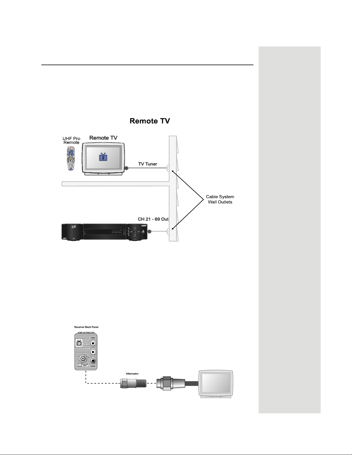
Connecting the Receiver to the TV(s) in Another Room(s)
Connecting the Receiver to the TV(s) in Another
Room(s)
This section describes how to connect the receiver CH 21–69 OUT connection to
the cable-ready remote TV located in another room away from the receiver. This
installation uses your in-home cable system. If your house does not have built-in
cabling, it will be necessary to run cables from the receiver to each remote TV.
Due to the difficulty of this installation, you should consider having this
professionally installed. Call DISH Network at 1-800-333-DISH (3474).
Note: When connecting to the home distribution (CH 21–69 OUT) coaxial port,
you must meet the FCC requirements in the Appendix. To meet these
requirements, an in-line coaxial attenuator has been included with your receiver
and may need to be installed using the following guidance:
• If connecting to your in-home cabling system to distribute the signal to a
TV(s) in other rooms, in most cases you will not have to install the
attenuator on the
• If connecting directly to a TV tuner port, you must install the attenuator in
the cable between the
CH 21–69 port for typical in-home cabling systems.
CH 21–69 OUT port and the TV tuner.
Page 31
Page 10
Chapter 2
Receiver Description and Installation
Tip: Using cable
labels makes it
easy to tell which
cables connect to
the receiver ports.
Inside the front
cover of this guide
are stickers that
are color coded the
same way as the
coaxial
connections.
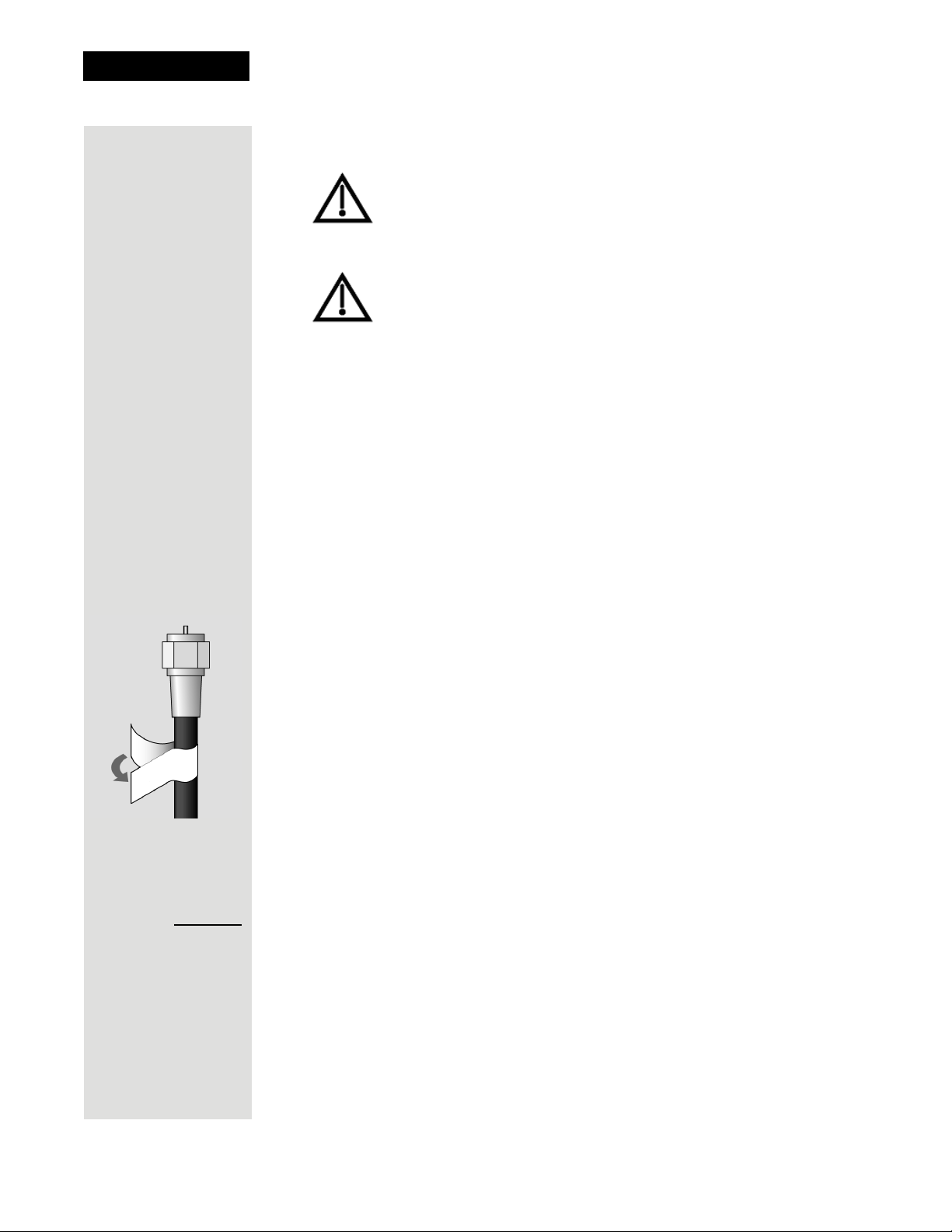
1. Connect the tuner input of the remote TV(s) in other rooms to an existing
wall cable outlet using a coaxial cable.
2. Turn on every remote TV connected to the in-home cabling system.
3. Find three channels next to each other on one of your remote TVs that do
not pick up any signals from off-air or cable broadcasts (they should show
nothing but snow or static). These channels must fall in one of the two
ranges below. For example, if you find that cable channels 75, 76, and 77 do
not pickup any broadcasts, pick these channels since they fall into the range
below for cable channels. Make sure these three channels on other remote
TVs also do not pick up broadcasts.
If you have an off-air antenna or cable connected to your inhome cable system, see Optional - Connecting to an Off-
Air Antenna or Cable following this section.
Make sure you are familiar with how to change channels on
your TV and if necessary how to switch your TV between
off-air and cable channels. During this procedure, it will be
necessary to change the channels on your TV(s) to tune to
these channels to see the video from the receiver. See your
TV user guide for instructions.
Channel:
Air/Cable
Air Mode - Select a channel between 21 and 69 if your TV(s) will be set
•
in Air Mode.
Cable Mode - Select a channel between 73 and 125 if your TV(s) will
•
be set in Cable Mode.
Note: The remote TV(s) will have to be set to the same channel mode,
either off-air or cable channel mode for this installation. See your TV user’s
guide for instructions on how to set your TV to off-air or cable channel
modes.
4. Pick the channel in the middle of the three you selected in step 3. Write that
channel down in the blank provided in the margin by step 5. For example, if
the three channels you picked in the preceding step were air channels 60,
61, and 62, pick channel 61 and write it in space provided in the margin by
step 5.
5. If your TV is in off-air mode for the channels you picked in step 4, circle
“Air” in the margin. If your TV is in cable mode for the channels you
picked in step 4, circle “Cable” in the margin.
6. Set all of your remote TV(s) to the channel mode (Air or Cable) you circled
in step 5.
7. Tune all of your remote TV(s) to the channel you wrote in step 5. This is the
channel you will use to receive your satellite programming.
Page 32
Page 11
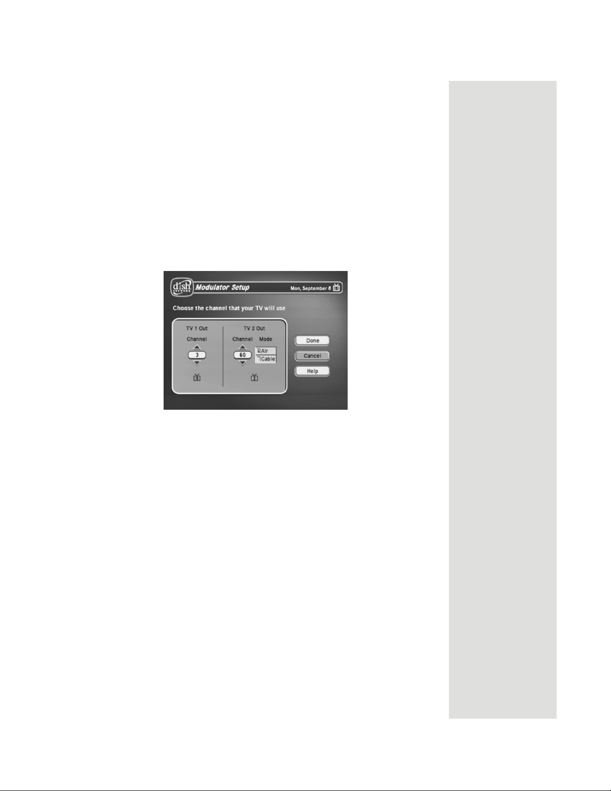
Connecting the Receiver to the TV(s) in Another Room(s)
8. Connect CH 21-69 OUT on the receiver to your existing wall cable outlet
using a coaxial cable.
Note: If you do not have an existing in-home cable system, you will need to
run coaxial cable to each TV in other rooms. If this is too difficult, you may
want to contact a professional to do this installation.
9. Place the yellow sticker on the
CH 21-69 OUT cable near where the cable
attaches to the receiver. The stickers are located inside the front cover of
this guide.
10. Turn on the nearby TV (the TV that gets programming from the
outputs).
11. Make sure the receiver's green
12. Select the
With the
Modulator Setup (MENU 6-1-5).
Modulator Setup screen displayed on the nearby TV, use Remote
TV1 indicator is on.
Control 1 to do the following:
TV1
a. Under
TV2 Out, select either Air (for off-air channel numbers) or Cable
(for cable channel numbers) based on what you wrote down in step 5.
b. Under
TV2 Out, use the UP and DOWN ARROWS to change the
modulator channel to the one you wrote in step 5.
c. Select
Done.
14. For some TVs, you must run a channel scan so that the TVs will find and
display the selected channel from the receiver. Run channel scan on all
remote TV(s), if available. See your TV user’s guide for instructions.
15. Confirm that you see a picture from the receiver TV2 output on your remote
TV(s).
• If your picture looks good, go to step 23.
• If your TV(s) do not have a picture or if it is not as clear as you would
like it to be, go to the next step.
Page 33
Page 12

Chapter 2
Receiver Description and Installation
16. You may need to change the cable connection on the splitter that sends the
TV signal throughout your house. The change that needs to be made is
move the cable coming from the receiver
the splitter to the input of the splitter using the instructions that follow.
The following figure shows an example of what your splitter may look like.
Your splitter may look different. The places where the splitter indicates
refers to all TVs connected to your cable system. The places where the
splitter indicates In refers to where the TV signal is fed into the splitter.
CH 21-69 OUT from the output of
OUT
1 Input, 4 Output (4-Way) Splitter
17. Find where the TV signal is distributed throughout your house. It should be
near where the cable TV service enters the house.
18. Disconnect the cable TV service cable or antenna cable from the splitter
input, if necessary. Make sure the disconnected cable is capped or otherwise
protected from the weather.
19. Disconnect the cable coming from the receiver CH 21–69 Out port from the
splitter. If you do not know which cable this is, go to the next step.
Otherwise, go to step 21.
20. If you have multiple TVs on the cable system, do the following to determine
which cable on the splitter is coming from the receiver:
• If you have at least some picture on your TV(s), turn on all remote TVs
connected to the cable system. Disconnect and reconnect each cable one
by one observing what happens to the TV(s). When all remote TVs lose
the signal, you have disconnected the receiver’s cable. If only some or
one TV loses the signal, then you have disconnected a cable from the
TV(s).
• If the above step does not work, disconnect one of the output cables and
connect to the splitter input. If you do not see a picture, connect the
cable back to its output. Repeat this step on every connection until you
get a picture on the remote TV(s).
Page 34
21. Reconnect the receiver’s cable to the input of the splitter.
22. Make sure you have a good picture on your remote TV(s).
Page 13
Connecting the Receiver to the TV(s) in Another Room(s)
23. If desired to remind you of which TV channel your satellite programming is
on, write the channel number you wrote in step 4 on a blank channel sticker
and place it on or near your remote TV(s). The stickers are inside the front
cover of this guide.
24. Confirm Remote Control 2 controls the receiver. See the next section for
instructions.
25. Program Remote Control 2’s RECOVER to the channel you selected in
step 5. See page 36 for instructions.
Confirming Remote Control 2 Operation
After the remote TV(s) have been connected to the CH 21–69 OUT using inhome cabling using the proceeding steps, do the following to make sure Remote
Control 2 controls the receiver:
1. Press the SAT button to put Remote Control 2 in SAT mode to control the
satellite receiver.
2. From a remote TV, use the Remote Control 2 arrow keys to move around
Point Dish screen. If you are able to move around in the Point Dish
the
screen, you confirmed that Remote Control 2 is controlling the receiver.
Programming the Recover Button for a Remote TV
Now that the channel for the CH 21–69 OUT to the remote TV(s) has been set,
the RECOVER button can be programmed to tune your TV back to this
channel.
1. Program Remote Control 2 to control your TV using the instructions in
Control Other Devices with the Remote Controls on page 106.
2. Press and hold the TV mode button until all the other mode buttons light up,
and then let go of the button. The TV mode button flashes.
3. Press the STAR (*) button.
4. Enter the three digits of your channel number. For example, if your remote
TV is set to channel 60, enter 0-6-0.
Tip: In Dual Mode,
Remote Control 1
is used to control
TV1 menus on the
nearby TV. Remote
Control 2 is used to
control TV2 menus
on the remote
TV(s).
5. Press the POUND (#) button. The TV mode button flashes three times.
Page 35
Page 14
Chapter 2
Receiver Description and Installation
Programming the Recover Button
Your remote controls come equipped with a RECOVER button that helps you if
you accidentally change the channel or video input on your remote TV and
cannot get the picture back from your satellite receiver. When you press the
RECOVER button as described on page 56, the remote control sends
commands to your remote TV to change channels or video inputs to try to get
you back to watching satellite programming.
When your Remote Control 2 is shipped from the factory, the RECOVER
button is set up to restore satellite TV viewing by tuning your TV to channel 3,
4, and other inputs (see page 56 for details). However, to use the RECOVER
button with your remote TV, you need to program the RECOVER button with
the specific channel (for example, channel 60) that you use to watch
programming. The following instructions describe how to program the
RECOVER button to tune your remote TV back to a selected channel.
Programming the Recover Button Channel
1. Program Remote Control 2 to control your remote TV using the instructions
in Control Other Devices with the Remote Controls on page 106.
TV2
2. Press and hold the TV mode button until all the other mode buttons
light up, and then let go of the button. The TV mode button flashes.
3. Press the STAR (*) button.
4. Enter the three digits of your channel number. For example, if your
remote TV is set to channel 60, enter 0-6-0.
5. Press the POUND (#) button. The TV mode button flashes three
times.
Removing the Recover Button Channel Programming
The following instructions describe how to reset the RECOVER button to the
way it was delivered to you from the factory.
1. Press and hold the TV mode button until all the other mode buttons
light up, and then let go of the button. The TV mode button flashes.
2. Press the STAR (*) button.
3. Press 0-0-0.
4. Press the POUND (#) button. The TV mode button flashes three
times.
Page 36
Page 15
Changing the TV1 and TV2 Output Channels
Changing the TV1 and TV2 Output Channels
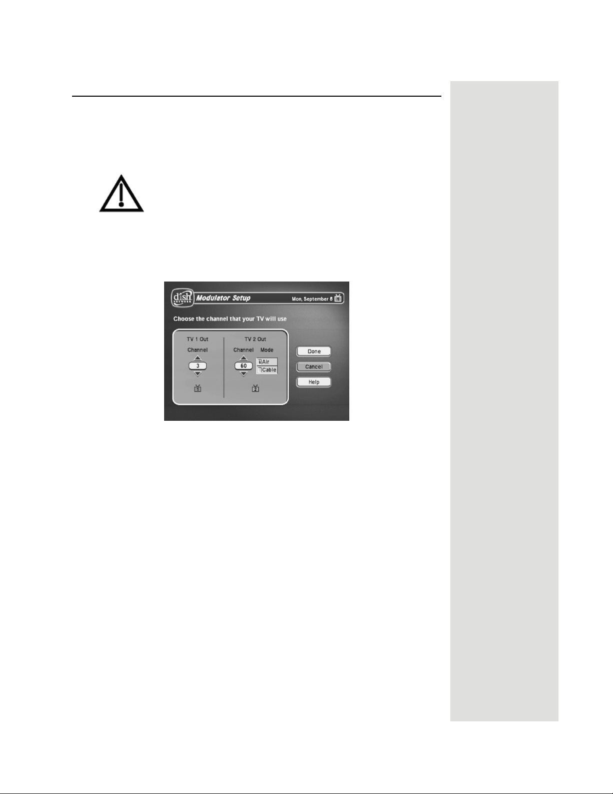
The receiver comes preset to use channel 3 for TV1 and off-air channel 60 for
TV2. If you are experiencing interference on the channels you are using, follow
these instructions to change the channel that
Make sure you are familiar with how to change channels on
your TV and if necessary how to switch your TV between
off-air and cable channels. When you change these receiver
output channels, you must also change the channels on your
TV(s) to tune to these channels to see the video from the
receiver. See your TV user guide for instructions.
TV1 or TV2 uses.
1. Press MENU-6-1-5 to open the
2. For
TV 1 Out, highlight the number under TV 1 Out. For TV 2 Out, skip to
Modulator Setup screen.
step 4.
3. Use the UP and DOWN ARROW buttons to change the modulator channel
either
3 or 4. Continue to the next step to set TV 2 Out or skip to step 7 if
you are finished making changes.
4. For
TV 2 Out, select either Air (for off-air channel numbers) or Cable (for
cable channel numbers).
5. Highlight the number under
TV 2 Out.
6. Use the UP and DOWN ARROW buttons to change the modulator channel
to one of the following:
•
Air Mode - Select a channel between 21 and 69.
•
Cable Mode - Select a channel between 73 and 125.
Tip: It’s easier to
set the output
channel from the
opposite TV. For
example, if you are
changing the output on TV1 (nearby
TV), use TV2
(remote TV) to
make the change.
When you save the
changes, simply
remember to
change the channel on the nearby
TV.
7. Select
Done to save the changes.
8. Change the channel on your TV(s) to match the channel(s) you selected.
9. If desired to remind you of which TV channel to tune to get satellite
programming, place a channel sticker near or on your TV to indicate the
correct channel.
10. If you changed your
TV 2 Out channel, repeat Programming the Recover
Button for a Remote TV on page 35.
Tip: The channel
stickers are located
inside the front
cover of this guide.
Page 37
Page 16
Chapter 2
Receiver Description and Installation
Connecting the Receiver to the Phone Line
Keep the receiver connected to an active telephone line so you can order PayPer-View programs and use all of the
other services from DISH Network.
Note: You may be able to use a wireless modem jack. However,
this may not support all the features of this receiver, such as Caller ID.
See www.dishnetwork.com for compatible modem products.
Note: If you have a Digital Subscriber Line (DSL), you may have to install a
DSL filter between the receiver’s back panel PHONE JACK and the telephone
wall jack to successfully connect with DISH Network. You can obtain a filter
from your DSL provider.
Phone Line Connection
Run a telephone cable with a standard RJ-11 connector from the receiver’s back
panel Phone Jack to an active telephone connection.
Phone System Setup
dish home Interactive TV features, and
You must also set up the receiver for your telephone system (touch tone or
rotary), and set a telephone number prefix, if you need a prefix to make an
outside call.
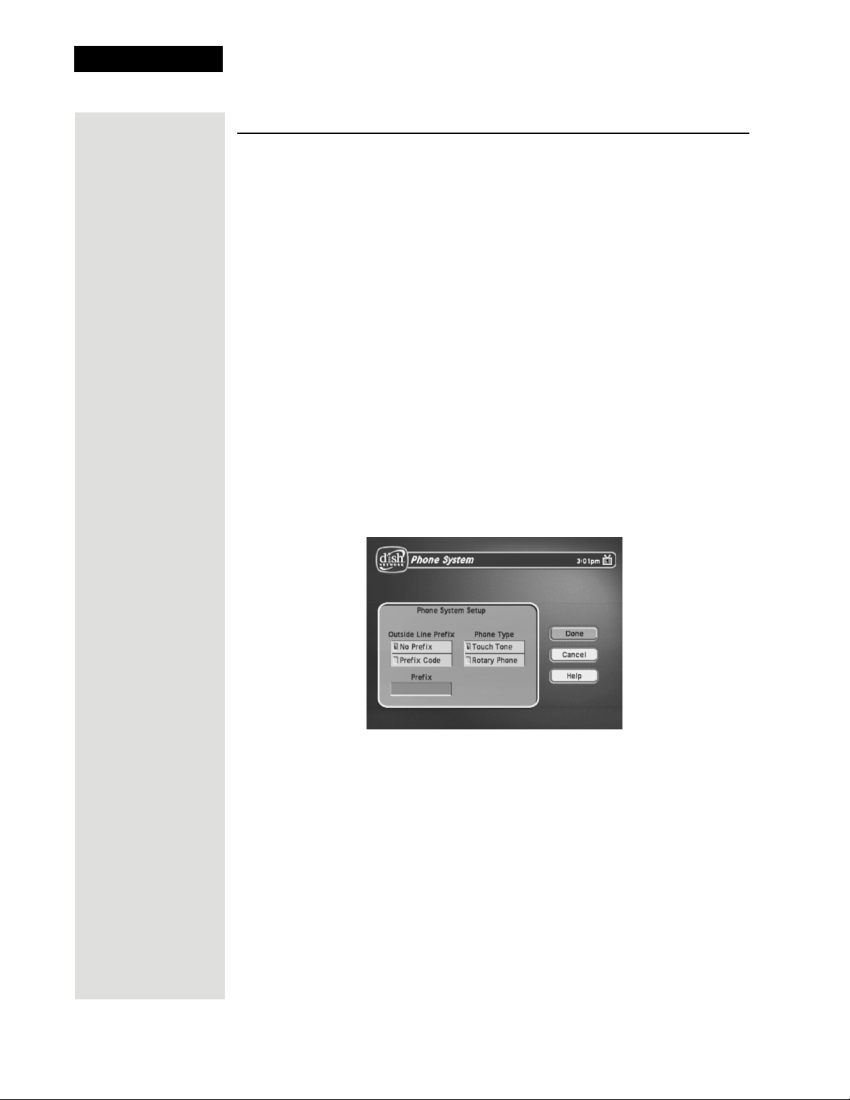
1. Display the
2. Select the
3. Select either the
Prefix
Note: The Outside Line Prefix is usually used only for business
Phone System screen by pressing MENU-6-1-4.
Touch Tone or the Rotary/Pulse option in the Phone Type list.
No Prefix or the Prefix Code option in the Outside Line
list.
installations. For most residential installations, all you need set is the
Phone Type.
Page 38
4. If you selected the
5. If you selected the
No Prefix option, select Save to finish.
Outside Line Prefix option, the receiver highlights the
box where you must enter the exact sequence you dial the phone to obtain
an outside line.
6. Select
Save to save the settings.
Page 17
Connecting the Receiver to a Dish Antenna System
Connecting the Receiver to a Dish Antenna System
Note: Before you can begin connecting your receiver to your dish antenna, you
must first complete the preceding sections on connecting your TVs to the
receiver. Then if you are installing a dish antenna system for the first time, see
Chapter 4 - Dish Antenna Installation. Otherwise, if you already have a dish
antenna system installed and peaked for maximum signal strength, complete the
following instructions to connect the dish antenna system to the receiver.
Note: You will need two available receiver connection ports on your installed
switch or LNBF to complete this installation. If these ports are not available,
you may need to upgrade your system with different or additional equipment.
See DISH Pro Wiring Diagrams in Chapter 4.
Tip: Using cable
labels makes it
easy to tell which
cables connect to
the receiver ports.
Inside the front
cover of this guide
are stickers that
are color coded
the same way as
the coaxial
connections.
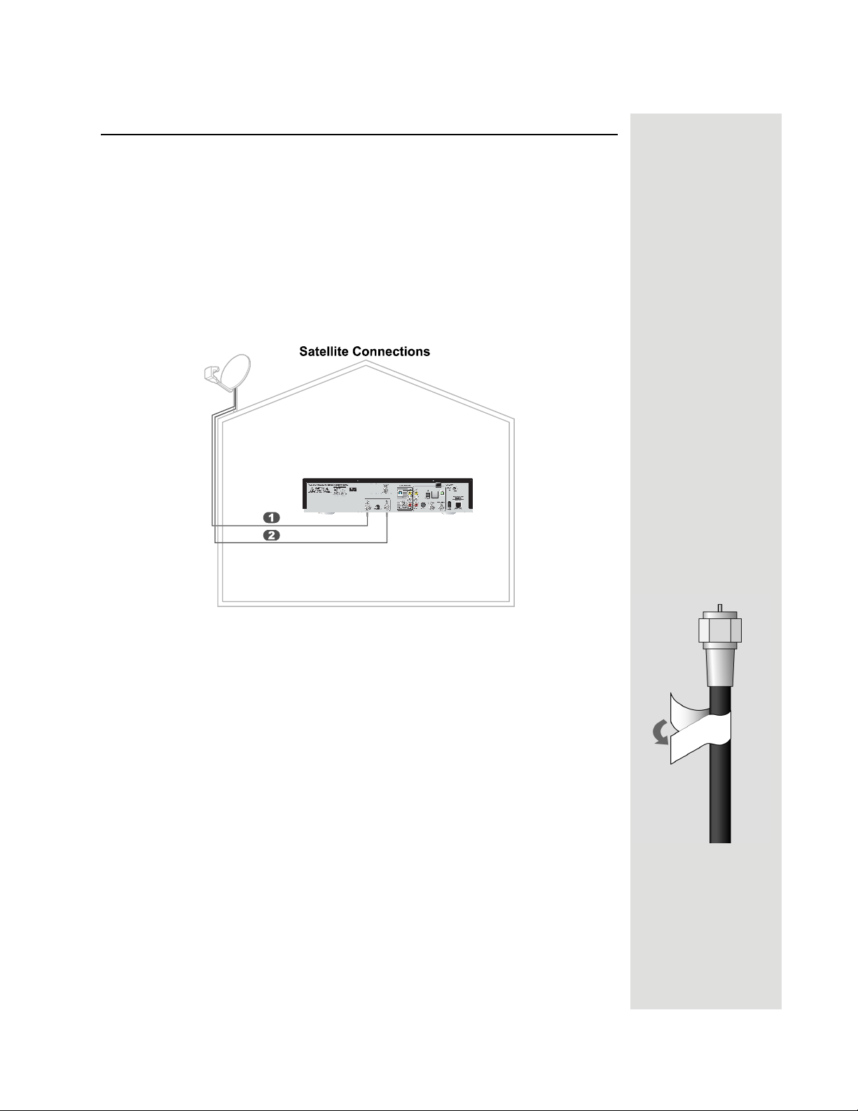
1. Connect two RG-6 coaxial cables between the
SATELLITE IN 2 ports on the receiver’s back panel to two available ports on
SATELLITE IN 1 and
either your switch or your LNBF in your existing system. See the wiring
diagrams in Chapter 4 for appropriate receiver connections in your system.
Note: If you are installing your receiver into a system with DISH Pro
LNBFs (and/or switches), you can have as much as 200 feet of cable
between the LNBF and the receiver. However, you must use only “RG-6
coaxial cables rated for 950 to 2150 MHz. Some cables may say “Swept
tested for 2150 MHz.” If you have any doubt about this, ask your DISH
retailer, or look on the container the cable came in. Do not use cable
company TV cables or cables from other satellite TV systems not rated for
950-2150 MHz. These other cables may cause signal loss. Do not use
existing cables such as RG-59. Use waterproof F-connectors outdoors.
Note: Some receivers include a DISH Pro Plus Separator that can be used
when installing the receiver with a single cable along with a DISH Pro Plus
Switch or LNBF.
2. Peel off the blue stickers and affix them to the cables close to where they
connect to the
SATELLITE IN 1 and SATELLITE IN 2 connections on the back of
the receiver.
Page 39
Page 18
Chapter 2
Receiver Description and Installation
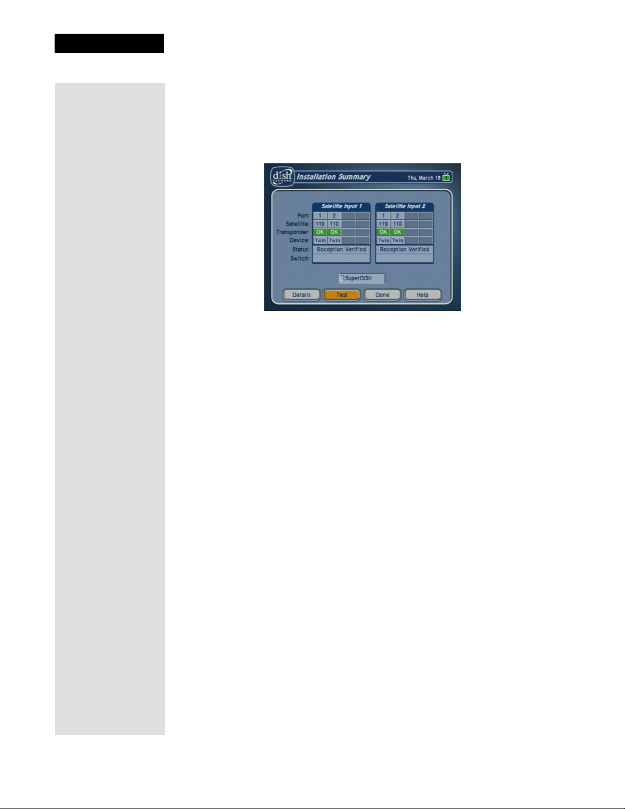
3. On Remote Control 1, press MENU-6-1-1 to display the Point Dish/Signal
screen on the nearby TV.
4. Select
5. The receiver begins performing the
Check Switch. When an attention screen displays, select Retest.
finished, the
Check Switch tests. When it is
Installation Summary screen displays.
6. Make sure that the information on the
Installation Summary screen
identifies your system correctly and shows all transponders for all satellites
in your system. Your screen may look different from the example above
depending on the dish antenna system you are using.
7. Select
8. Select
OK to go to the Point Dish/Signal screen.
Cancel to exit the Point Dish menu. An Attention screen will open
asking the mounting and positioning of your dish is complete with a
Locked indication in the Point Dish screen. If the answer is yes, select
Yes.
9. After you select Yes, the receiver will begin taking a software upgrade. You
will see a Warning that
downloaded into your receiver
Vital program information will now be
. You will also see a status bar showing the
progress of this upgrade.
10. Once the software upgrade is complete, you will see a message that your
receiver’s memory is being upgraded.
11. Do not disturb the receiver while the receiver’s memory is being upgraded.
Note: If you are installing other DISH Pro or DISH Pro Plus receivers, be
sure to run
Check Switch on all of them, and allow them to take the
necessary software upgrade.
12. When the memory upgrade is complete, you should be watching TV. Your
dish antenna installation is now complete.
Page 40
Page 19
Optional - Connecting VCRs to the System
Optional - Connecting VCRs to the System
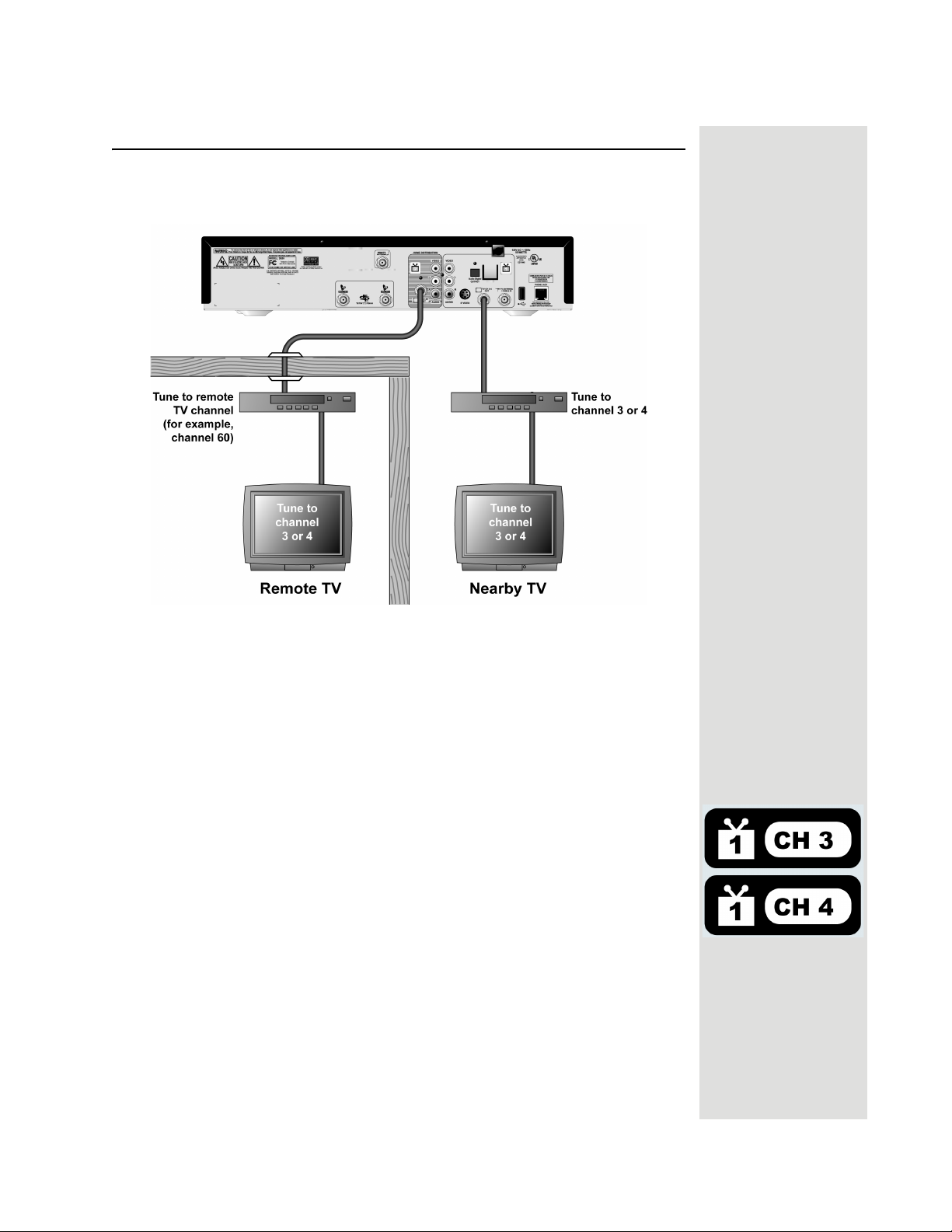
The diagram below provide example of how to connect VCRs to your satellite
TV system. Your installation may be different.
Connecting a VCR to the Nearby TV
1. Connect a coaxial cable from the CH 3-4 OUT output on the receiver to the
nearby VCR’s tuner port.
2. Connect a coaxial cable from the output on the VCR to the nearby TV’s
tuner port.
3. Plug in and turn on the nearby VCR and TV.
4. Set the VCR output to Channel 3 or 4 as set on page 37.
5. Tune the nearby VCR and TV to Channel 3 or 4 as set on page 37.
6. Place a
nearby TV. This sticker will remind you which channel to use to watch
satellite programming. The stickers are located in the inside front cover of
this guide.
TV1 channel sticker (Channel 3 or 4 as set in step 5) on or near your
Page 41
Page 20
Chapter 2
Receiver Description and Installation
Connecting a VCR to the Remote TV
For this installation, always leave your VCR powered on so that
the TV can receive satellite programming. If you turn off your
VCR, your TV will not be tuned to the correct channel to receive
satellite programming.
1. Connect the tuner input of the remote VCR to an existing wall cable outlet
using a coaxial cable.
2. Connect a coaxial cable from the output on the VCR to the remote TV’s
tuner port.
3. Plug in and turn on the remote VCR and TV.
4. Tune the remote VCR to the remote TV channel that you use to watch
satellite TV programming (for example, channel 60) as set on page 33.
5. Write the channel number you tuned your VCR to in the previous step on
one of the
sticker will remind you which channel to use to watch satellite
programming. The stickers are located in the inside front cover of this
guide.
6. Set the VCR output to channel 3 or 4.
7. Tune the remote TV to the same channel that you set your VCR to in step 6.
TV2 channel stickers. Place the sticker on or near the VCR. This
8. Write the channel number you tuned your TV to in the previous step on one
of the
TV2 channel stickers. Place the sticker on or near the TV. This sticker
will remind you which channel to use to watch satellite programming. The
stickers are located in the inside front cover of this guide.
Optional - Connecting to an Off-Air Antenna or Cable
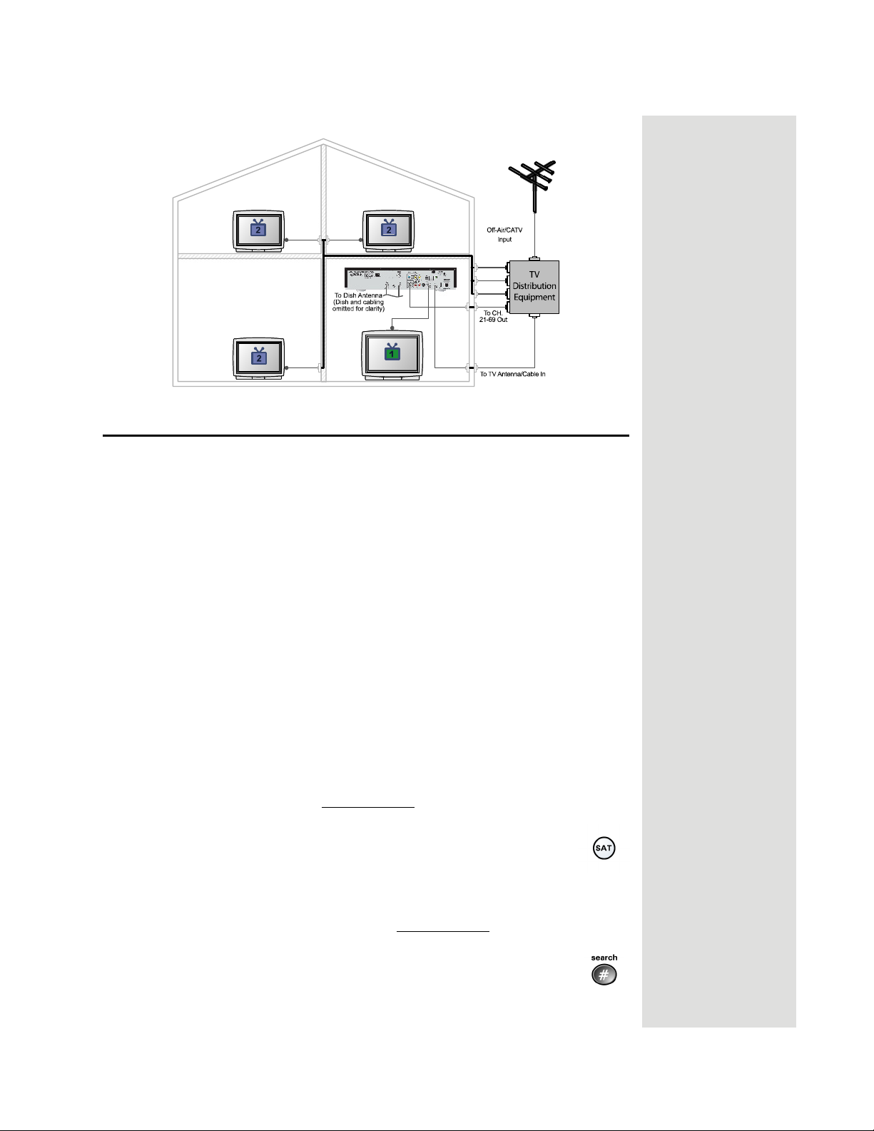
If you want to receive channels from an off-air antenna or cable in addition to
your satellite receiver programming, connect the off-air antenna/cable into your
TV distribution equipment.
For the nearby TV receiving programming from
antenna cable needs to be connected to the
For remote TVs receiving programming from
needs to be connected to your TV distribution equipment. When adding this
connection, the FCC requires that your install appropriate equipment between
the off-air antenna/cable and the satellite TV receiver to prevent you from
accidentally retransmitting DISH Network programming (see FCC Compliance
in the Appendix).
TV distribution equipment devices include coax panels, amplifiers
or super home nodes, and are available through many companies. See
www.dishnetwork.com for a list of approved equipment.
CH 3–4 OUT, the off-air
TV ANTENNA/CABLE IN port.
CH 21-69 OUT, the off-air antenna
Page 42
Page 21
Optimize Your Remote Controls
Optimize Your Remote Controls
Change the Address
When you receive your system, both remote controls and the receiver have been
set to communicate on address 1. However, because UHF signals travel long
distances and go through walls, a neighbor’s UHF Pro remote could control
your receiver by mistake if they are on the same address.
Note: You can also use this procedure to change the Primary Remote Address
for IR Remote Control 1 on a nearby TV, if necessary. However, if you are using
a UHF Pro remote to control
address.
To handle this situation, you can change address on Remote Control 2 and the
receiver as follows:
1. Make sure you turn on the TV.
2. Press the front panel SYSTEM INFO button to display the
screen.
The
System Info screen shows the Secondary Remote Address.
Write down this address:
3. Press and hold the SAT button on Remote Control 2 for about
three seconds, until all of the mode buttons light up, and then let
go of the SAT button.
4. Use the NUMBER PAD buttons to enter any number between 1 and 16, but
not the one you wrote in step 2.
Write down the number you entered:
TV1, use the instructions on page 46 to change the
System Info
5. Press the POUND (#) button. If you entered the address correctly,
the SAT mode button will flash three times.
Page 43
Page 22
Chapter 2
Receiver Description and Installation
6. Press the RECORD button.
7. Make sure the
System Info screen is the same as the one you entered in step 4. If
it isn’t, the remote cannot control the receiver.
8. Press the SELECT button to close the
Information
Checking the Remote Control Address
1. Press and hold the SAT mode button for three seconds, until all of
the mode buttons light up, and then let go of the SAT button.
2. Press the POUND (#) button twice. The SAT mode button will
flash the same number of times as the address number (three
flashes means address 3).
Adjusting the Remote Control Antenna
Attention: If your UHF Pro Remote Control 2 isn’t working very
well from far away, you may be experiencing interference from
objects near your receiver. To improve your remote control’s
range, try any or all of the following:
• Place the receiver higher than all of the other equipment in your
• Provide room above the receiver so that the antenna can be
• Place the UHF antenna outside the entertainment center by
• Try moving the receiver to other locations.
• Move all nearby off-air antennas away from the UHF remote
• Attach a UHF attenuator.
Secondary Remote Address you see on the
Important System
screen.
entertainment center.
installed straight up. If this is not possible, tilt the UHF antenna
at about a 30° angle.
using a coaxial cable to connect the antenna to the receiver.
antenna. Do not place an off-air antenna on your receiver.
Page 44
Attach a UHF Attenuator
Stray UHF signals can block signals from the remote control to the receiver. To
prevent this problem, you can install the attenuator provided with the satellite
receiver if it is not being used for TV connections as described on page 31.
Otherwise, obtain a 10 dB attenuator (you can buy one from a consumer
electronics parts store).
Note: This will help keep out stray UHF signals, but also cut down how far
away you can use the remote control.
Page 23
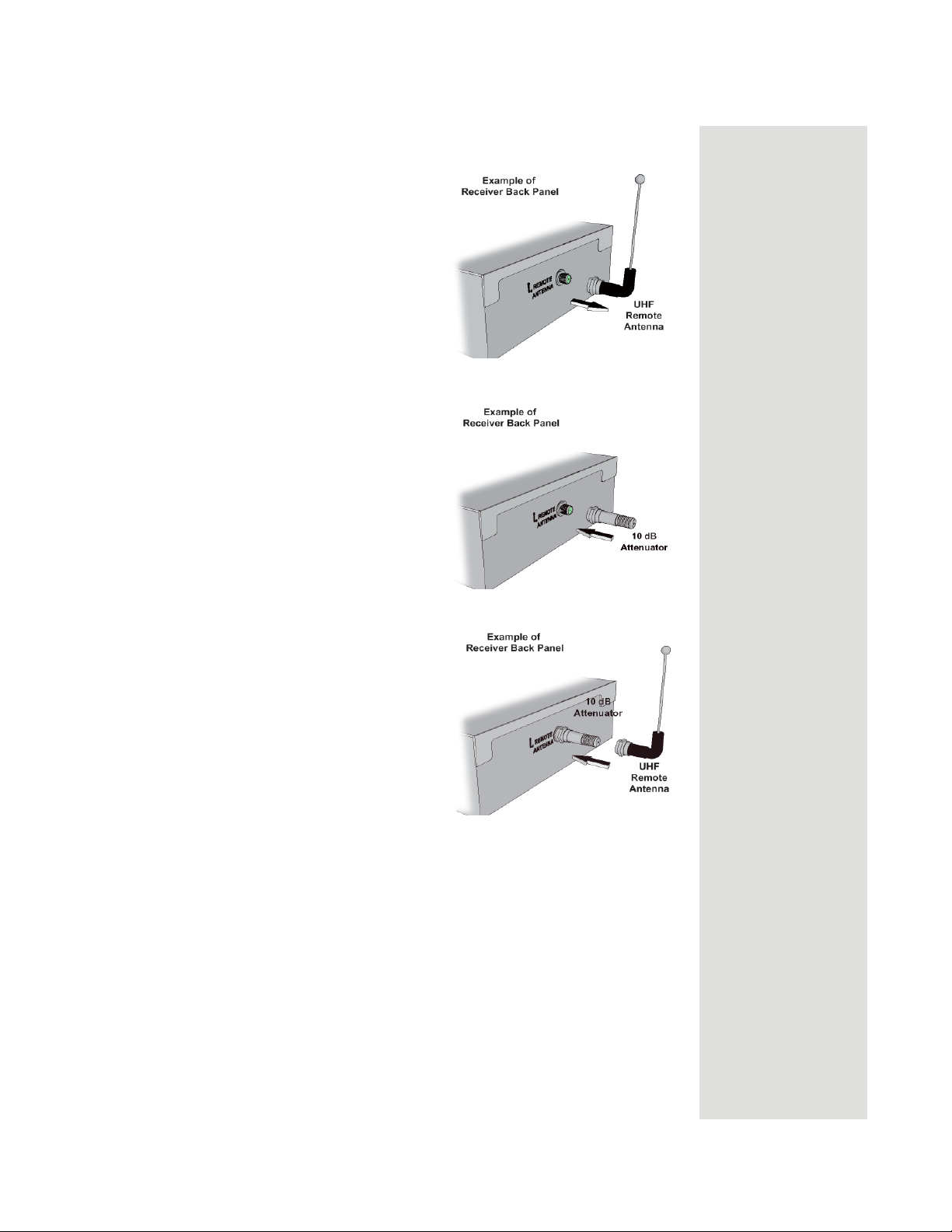
1. Take the UHF antenna off of the
receiver’s back panel UHF
Remote Antenna input
2. Put the attenuator onto the UHF
Remote Antenna input.
Optimize Your Remote Controls
3. Put the UHF antenna onto the
attenuator.
Page 45
Page 24
Chapter 2
Receiver Description and Installation
Setting Up TV1 to Operate in UHF Pro
You can set your receiver to operate your TV1 using another UHF Pro remote
control (sold separately) by completing the following instructions:
If you set up your receiver to operate the side using UHF Pro,
the two UHF Pro remotes for this receiver will interfere with
each other when operated at the same time. This may prevent
the remotes from operating the receiver momentarily.
1. Perform the following using an existing remote control:
a. Open the
TV1 UHF Pro Setup screen by pressing MENU-6-1-8 on the
remote control.
b. Select
c. Select
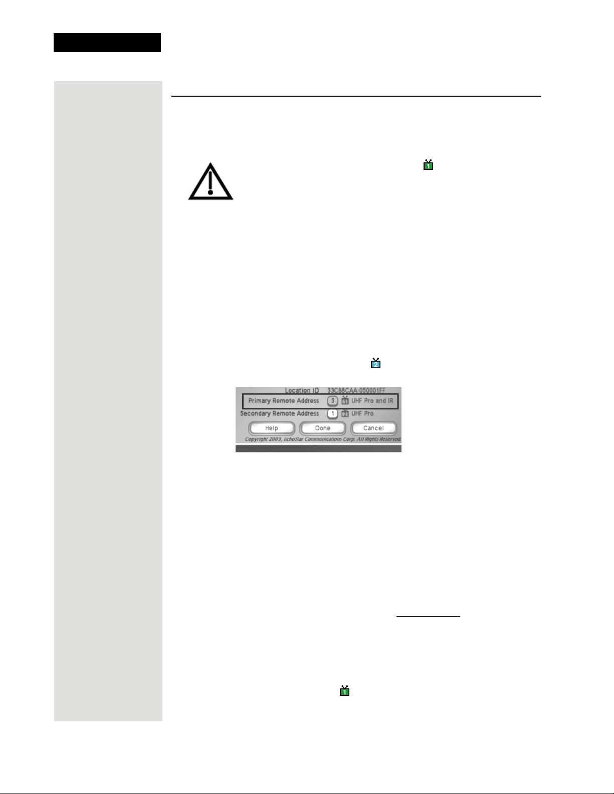
d. Move the highlight to the address for the
Enable from the TV1 UHF Pro Setup screen.
System Info to open the System Information screen.
Primary Remote Address as
shown below. This is important - if you do not do this, your remote will
change the receiver's
Remote Control 1 to control the
Secondary Remote Address and cause your
side of your receiver.
Note: Highlight the
Primary Remote
Address.
2. Perform the following using the UHF Pro remote that you are going to use
to control TV1:
a. Press and hold the SAT mode button about three seconds, until all the
mode buttons light up, and then let go of the SAT button. The SAT
mode button will blink.
b. Use the NUMBER PAD buttons to enter any number from 1 to 16,
except for the number shown by the
Secondary Remote Address. The
SAT mode button goes out after you enter each digit, and then lights up
again.
Write down the number you entered:
Page 46
c. Press the POUND (#) button. If you entered the address correctly, the
SAT mode button will flash three times.
d. Press the RECORD button.
e. Make sure the
Remote Address
System Information screen shows that the Primary
shows UHF Pro and IR and that this address
matches the number you entered in step b.
Page 25
Setting Up TV1 to Operate in IR
Setting Up TV1 to Operate in IR
The following instructions describe how to set up TV1 to operate in IR only.
1. Perform the following with an existing remote control:
a. Open the
TV1 UHF Pro Setup screen by pressing MENU-6-1-8 on the
remote control.
b. Select
c. Select
Disable from the TV1 UHF Pro Setup screen.
System Info to open the System Information screen.
2. Perform the following with an IR remote control, such as a Remote Control
5.0 (as shown on the back of the remote), that you intend to use to control
TV1:
a. Press the RECORD button. The
b. Make sure the
Remote Address
System Information screen shows that the Primary
shows IR.
Done button should be highlighted.
Page 47
Page 26
Chapter 2
Receiver Description and Installation
Notes
Page 48
 Loading...