

Page 1
Chapter 2
Receiver Description and Installation
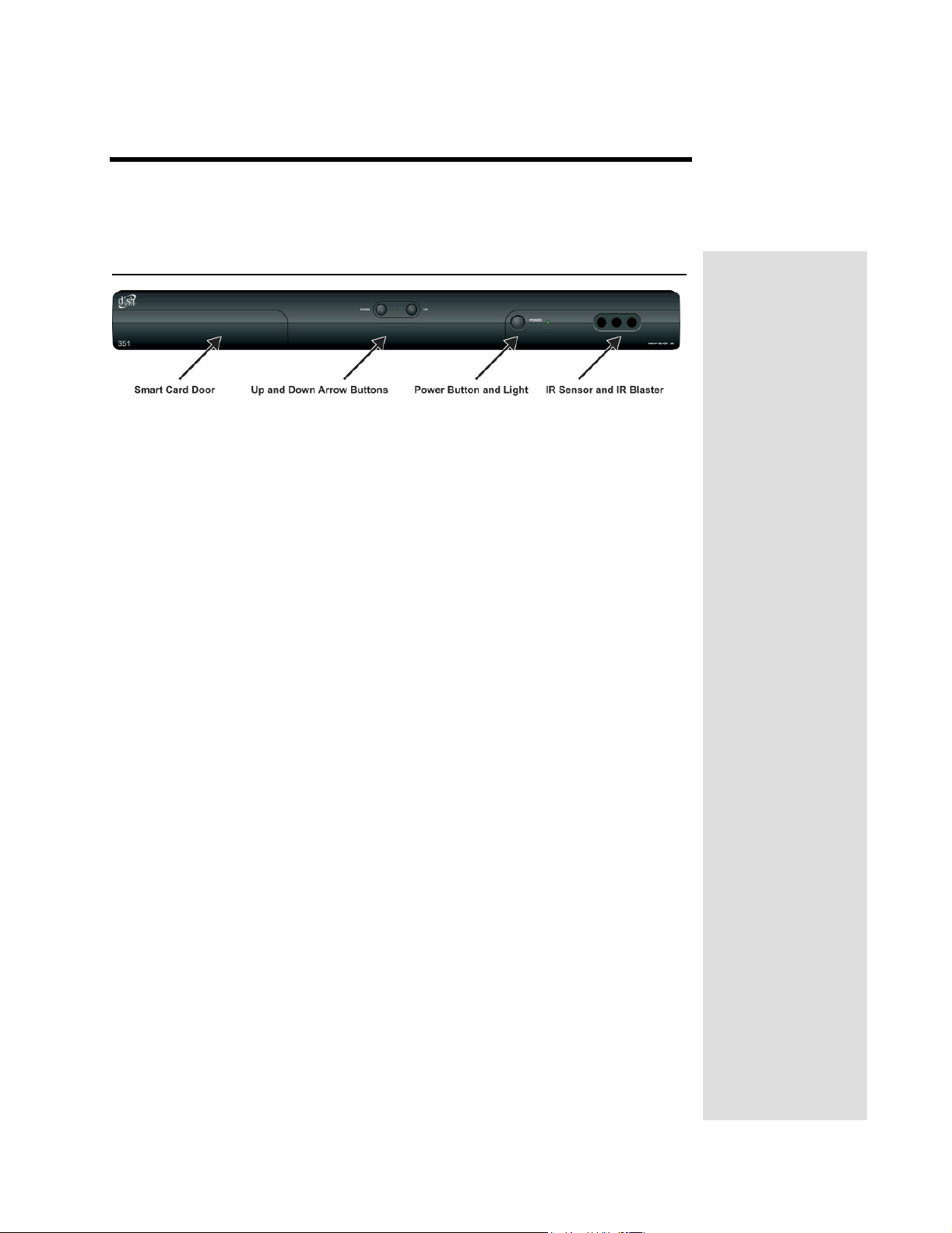
The Receiver Front Panel
Smart Card Door
Behind this door is a slot for a future smart card. No smart card is included with
this receiver.
Up and Down Arrow Buttons
The UP and DOWN buttons change the channel on the receiver.
IR Sensor and IR Blaster
The IR SENSOR receives IR signals from the remote control. The IR
BLASTER transmits IR signals to control a VCR in order to perform automated
recordings.
Power Button and Light
The GREEN LIGHT on the front panel lights up when you press the receiver’s
POWER button ON and goes out when you press the POWER button OFF.
Page 9
Page 2
Chapter 2
Receiver Description and Installation
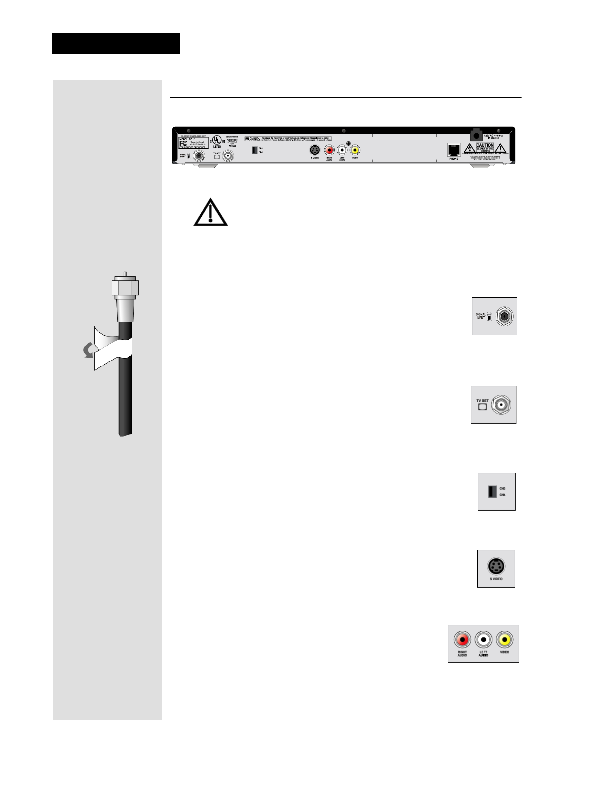
The Receiver Back Panel Connections
Tighten the connections by hand only. If you use a wrench you
might over-tighten the connections and cause damage that
would not be covered by the Limited Warranty.
The back panel of the receiver provides the connections that you use to
connect the receiver to other electronic devices. It also provides the receiver
power cord and telephone jack. Depending on the setup that you have, you
may only use some of these connections.
Signal Input
The television signal enters your receiver through this
connection. Connect an RG-6 coaxial cable from your wall
outlet to the S
color coded black. Remember to tighten by hand only. Wrap the black label,
located inside the front cover, around the end of the cable to identify it.
IGNAL INPUT connection. The connector is
Tip: Using cable
labels makes it
easy to tell which
cables connect to
the receiver ports.
TV Set
Use the TV SET connector as the primary means of
connecting your receiver to your TV. Use either an RG-6 or
an RG-59 coaxial cable. The connector is color coded white.
Remember to tighten by hand only. Wrap the white label, located inside the
front cover, around the end of the cable to identify it.
Channel 3/4 Switch
If you use the TV SET connection as described above, set the
HANNEL 3/4 SWITCH to the channel for the signal output.
C
Select a channel that is not being used by a cable or local
television channel.
S-Video
The S-VIDEO connection provides high quality standard
definition video output. If you use this output for video, you
must connect the audio with the two RCA A
(color coded Red and White).
UDIO OUTPUTS
Phono (RCA) Audio/Video Outputs
These color coded RCA A/V OUTPUT connectors
provide good quality standard definition video and
audio. Use a Phono RCA-type cable to connect these
outputs to your TV or other device.
Page 10
Page 3
Telephone Jack
Connect a telephone cable with a standard RJ-11 telephone connector
to the receiver here, and then connect the cable to an active telephone
line.
Note: The receiver must be connected at all times to an active telephone line.
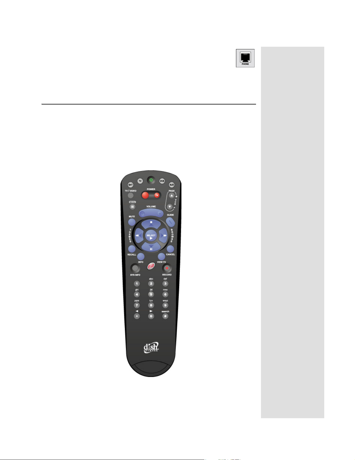
Remote Control
The remote control gives you easy access to the features of your satellite
receiver.
Basic remote control setup is explained here, using the SAT button on the
remote.
Complete instructions on how to use the remote, as well as the rest of the
system, are in Chapter 3.
Remote Control
Tip: If you have
the receiver
connected to a
DSL (Digital
Subscriber Line)
phone line and it
cannot dial out,
you may have to
install a DSL filter
between the
receiver and the
telephone jack
on the wall.
Page 11
Page 4
Chapter 2
Receiver Description and Installation
Remote Control Batteries
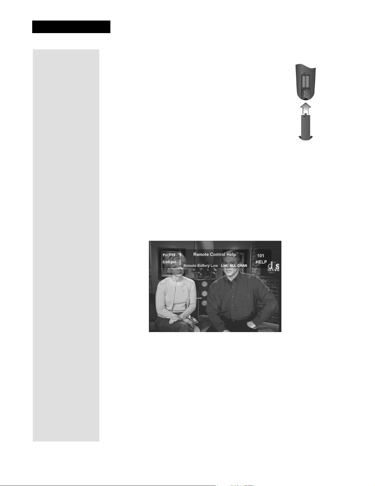
The remote control comes with AAA batteries, which need to be
installed when you first receive your system. When you replace
old batteries, you should replace all of the batteries. Use
batteries of the same kind, for example, alkaline or carbon zinc;
and don’t mix batteries of different kinds. Alkaline batteries last
longer than carbon zinc.
1. Press down on the top of the battery cover and push in the
direction of the arrow. The cover will snap off.
2. Take out all of the old batteries.
3. Put the new batteries in. Make sure you match the plus (“+”)
ends with the plus markings on the battery case.
4. Fit the battery cover’s bottom tab back into the slot at the bottom of the
battery case, and slide the cover back into place.
On Screen Low Remote Battery Warning
When you see a low battery warning message below the Program
Banner
replaced.
, the batteries in your remote control are weak and need to be
Page 12
Page 5
Remote Control Settings
Change the Address
The remote control and receiver can operate on any one of 16 addresses;
however, they must both be on the same address for the remote to control the
receiver. This section explains how to change the address in both devices.
Note: Do not change the address of the remote unless absolutely necessary
because the remote cannot control the receiver if the two devices have different
addresses.
Remote Control Settings
1. Press SYS INFO button on your remote control. The
Information
Write down this address: _____________
2. Press and hold the SAT button on your remote control for about
three seconds, until all of the mode buttons light up, and then let
go of the SAT button.
3. Use the NUMBER PAD buttons to enter any num-
ber between 1 and 16, but not the one you wrote in
step 1.
Write down the number you entered:___________
4. Press the POUND (#) button. If you entered the
address correctly, the SAT mode will flash three times.
5. Press the RECORD button.
Note: Make sure the
System Information screen is the same as the one you
entered in step 3. If it isn't, the remote cannot control the
receiver.
6. Press the SELECT button to close the System Information
screen.
screen displays and shows the Remote Address.
Remote Address you see on the
System
Checking the Remote Control Address
1. Press and hold the SAT mode button for three seconds, until all
of the mode buttons light up, and then let go of the SAT button.
2. Press the POUND (#) button twice. The SAT mode button will
flash the same number of times as the address number (for
example: three flashes means address 3).
Page 13
Page 6
Chapter 2
Receiver Description and Installation
Connecting Your Receiver
Connection Diagram Example
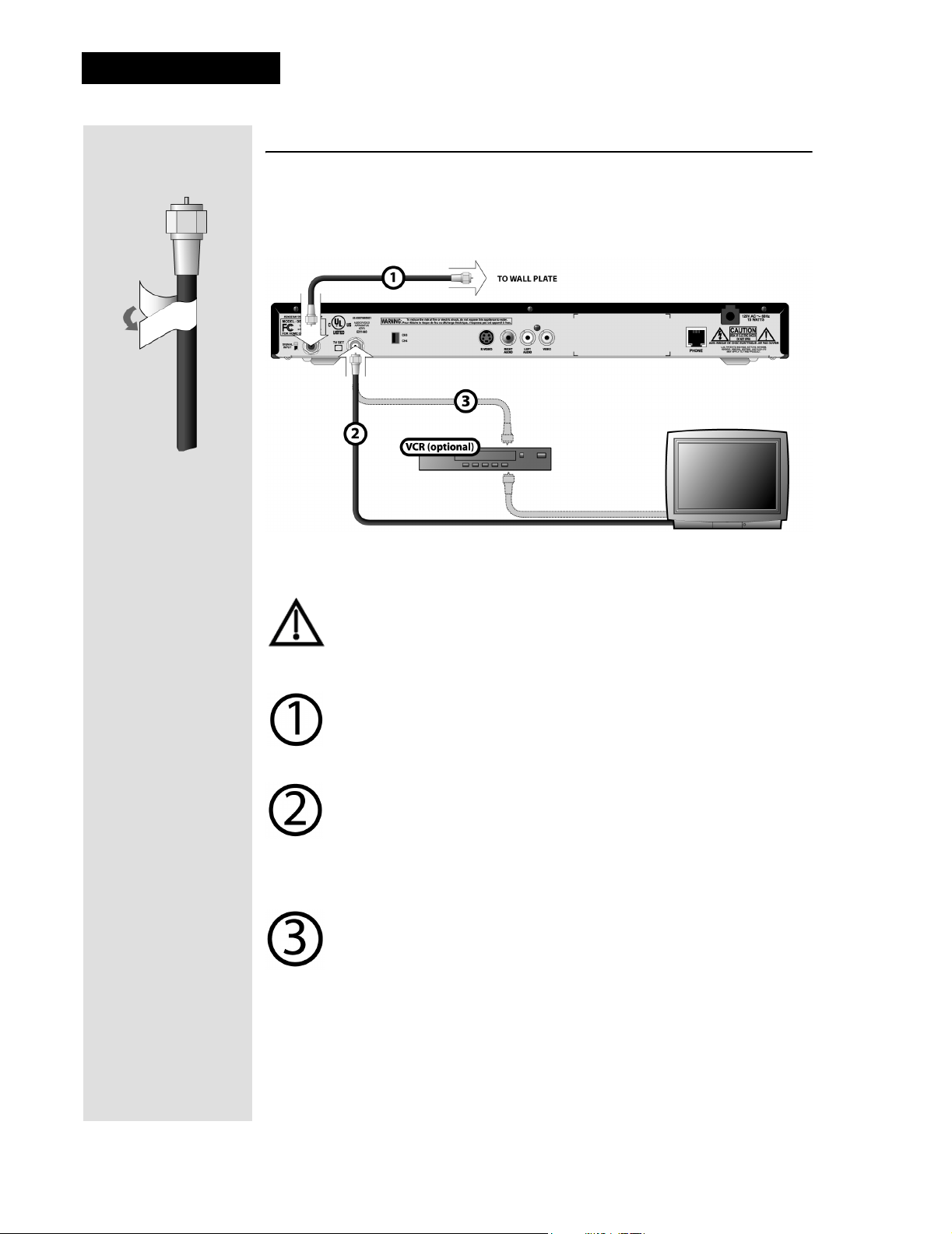
The diagram below is an example of how to connect your receiver, TV, and
VCR.
Tip: Using cable
labels makes it
easy to tell which
cables connect
to the receiver
ports. Inside the
front cover of
this guide are
stickers that are
color coded the
same way as the
coaxial
connections.
Typical Connection Procedure
Tighten all the coaxial cable connections only by hand. Using a
wrench may over-tighten the connections, causing damage. Such
damage is not covered by the Limited Warranty.
IGNAL INPUT - Connect a coaxial cable between the wallplate
S
and S
IGNAL INPUT on the back of the receiver. Peel off the black
sticker and affix it to the cable close to where it connect to the S
NPUT connection on the back of the receiver.
I
TV SET to a TV - Connect a coaxial cable between the TV SET
output on the receiver and the TV’s tuner input. Be sure to tune the
TV to the channel you use to watch satellite TV (either Channel 3 or 4
as indicated on the
it to the cable close to where it connect to the TV SET connection on
the back of the receiver.
TV SET to a VCR (Optional) - Connect a coaxial cable between the
TV SET output on the receiver and the VCR’s tuner input. Connect
another cable between the VCR’s modulator output and the TV’s
tuner input. Be sure to set the
VCR to the same channel (either 3 or 4) you use to watch satellite TV.
Tune your TV and VCR to the same channel you selected on the
CH 3/4 switch. Peel off the white sticker and affix it to the cable close
to where it connect to the TV SET connection on the back of the
receiver.
CH 3/4 switch). Peel off the white sticker and affix
IGNAL
CH 3/4 switch on the receiver and on the
Page 14
Page 7
Performing the QAM Frequency Scan
Performing the QAM Frequency Scan
Note: When you turn your receiver on it may display the QAM Frequency
Scan and Signal Strength screen automatically. If it does, then skip down
to Step 5.
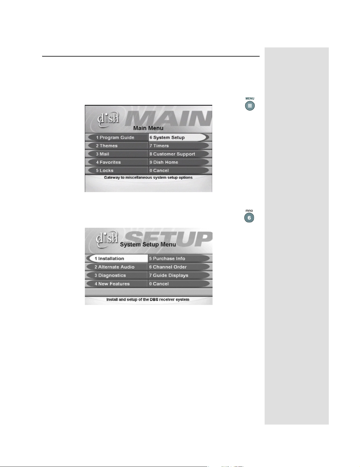
1. Press the MENU button to open the Main Menu.
2. Select the System Setup option on the Main Menu. The Sys-
tem Setup Menu screen is displayed.
Page 15
Page 8
Chapter 2
Receiver Description and Installation
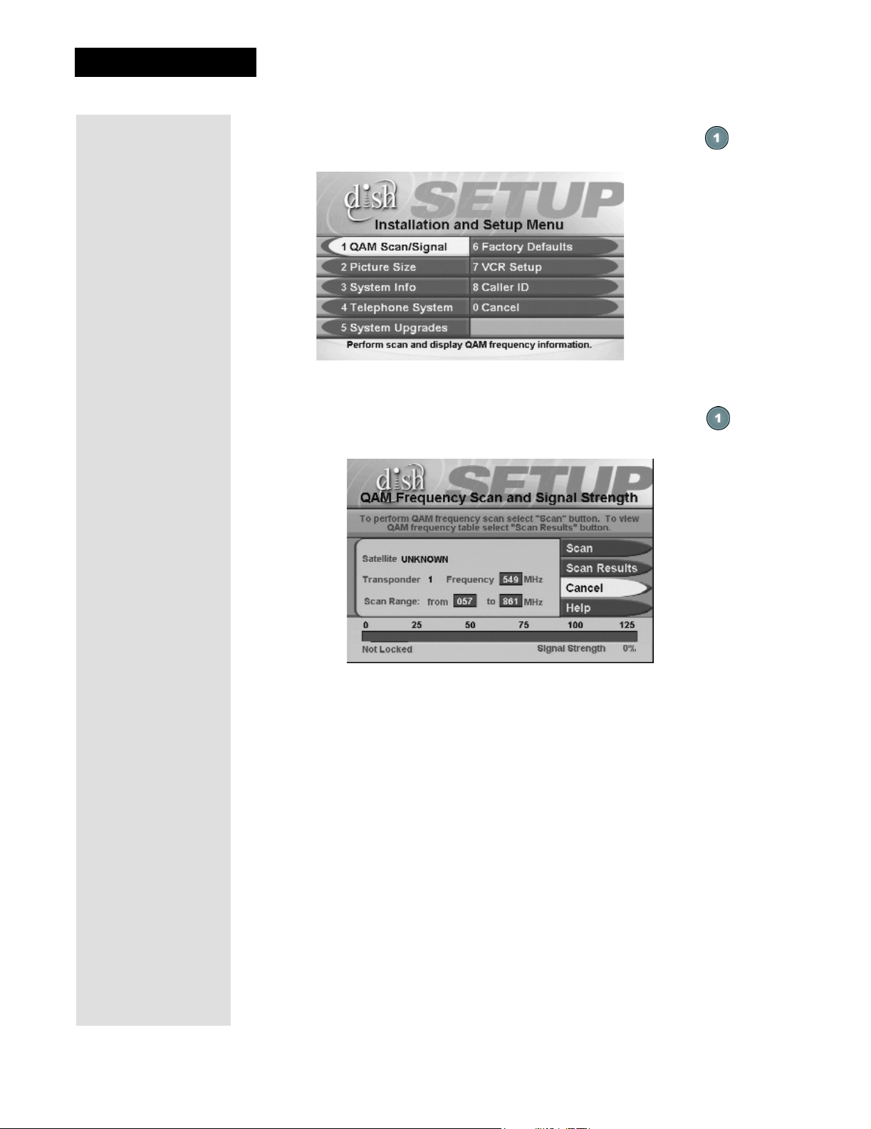
3. Select the Installation option on the System Setup Menu.
The Installation and Setup Menu screen is displayed.
4. Select the QAM Scan/Signal option. The QAM Fre-
quency Scan and Signal Strength screen is displayed.
Page 16
Page 9
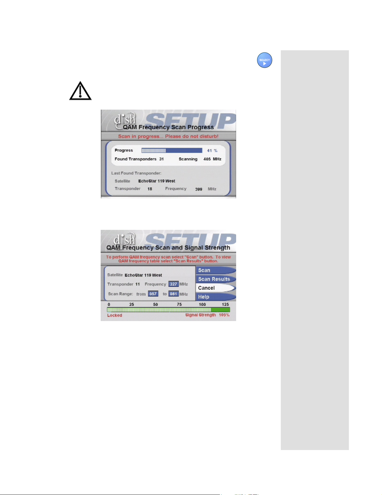
5. Select the Scan option.
While scanning, the receiver displays the QAM Frequency
Scan Progress screen. The scan can take a few minutes.
Note: The receiver creates a table of available satellite
transponders with the corresponding QAM frequencies. This
table is required for correct operations.
Performing the QAM Frequency Scan
The receiver will again display the QAM Frequency Scan and Signal
Strength screen.
Observe that the signal strength bar is now green and displays the word
Locked.
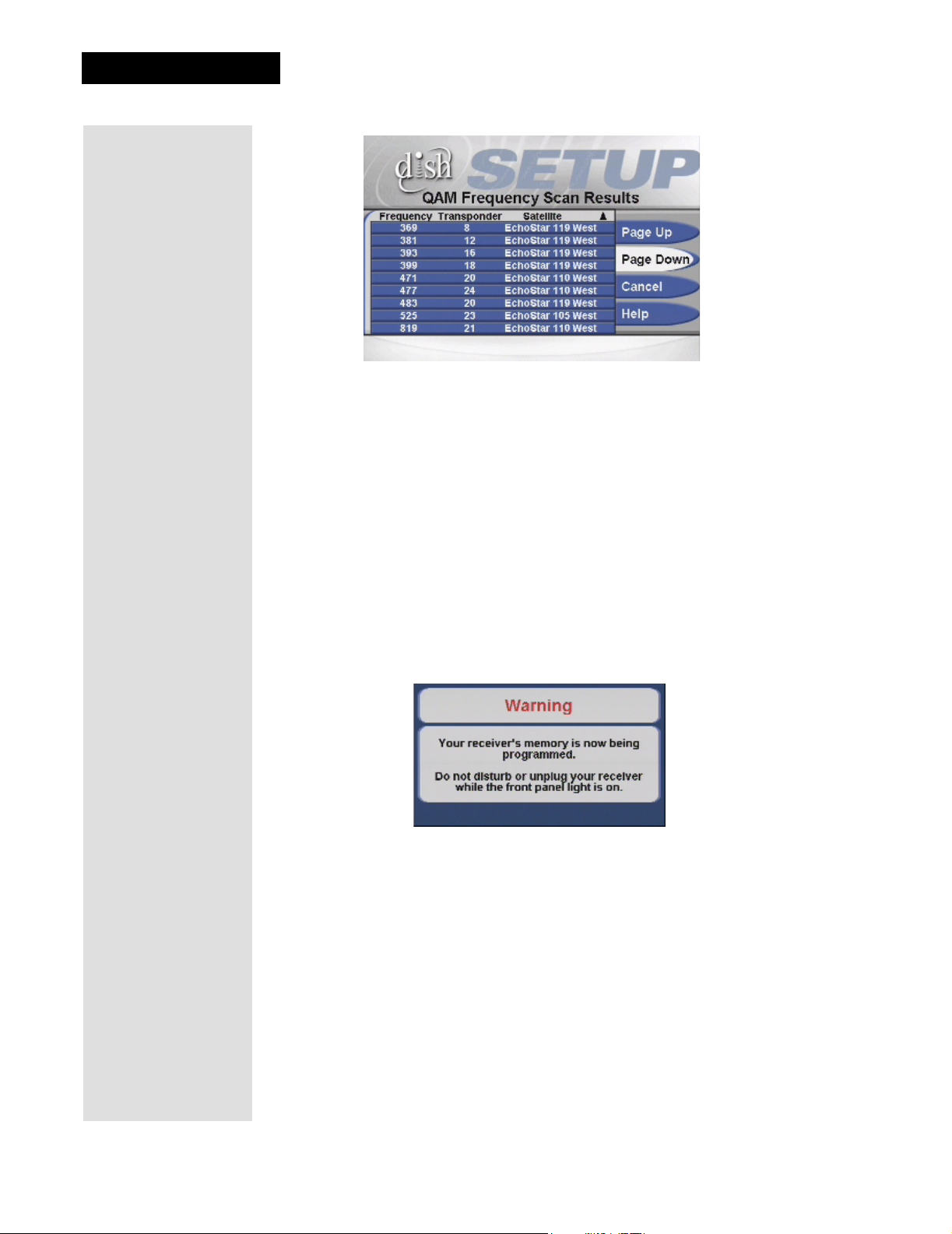
6. To see the completed scan, select the Scan Results button. The receiver
displays the QAM Frequency Scan Results screen.
Page 17
Page 10
Chapter 2
Receiver Description and Installation
Note: If the Results menu displays No Transponders have been
found, check your cable connections and return to step 5 to repeat the
scan.
If the second scan does not find any transponders, ask your dwelling
complex owner for assistance or call the Commercial Customer Service
Center at 1-800-454-0843.
7. Select the Cancel option to exit the Results menu.
8. Select the Cancel option to exit the Scan and Signal Strength
screen.
9. The receiver will display an Attention message pop up asking you to
verify that the satellite signal is locked and the QAM frequency scan
has been completed successfully. Select the Yes option.
The receiver will begin accepting a transmission or, download, of the
latest software. You will see the message shown below:
A progress bar across the bottom of the screen will show the software
upgrade as it downloads. Once the download is complete, you will see a
second message that the receiver’s memory is now being programmed.
Note: This message may disappear and your screen may go blank for a
few minutes. This is normal and does not indicate a problem with the
receiver.
Your receiver will now display the Preview Channel, which tells you
about available programs, channels and services.
To activate your programming on your receiver you must call the
Commercial Customer Service Center at 1-800-454-0843. See the
Quick Start Guide in Chapter 1 for complete instructions.
Page 18
Page 11
Connecting Your Receiver to a Phone Line
Connecting Your Receiver to a Phone Line
Yo u must keep your receiver connected to an active telephone line. Otherwise,
you may not be able to order pay per view programs or use all of the DISH
Interactive features. Run the RJ-11 telephone cable supplied with your receiver
from your receiver's back panel P
Note: You may be able to use a wireless telephone extender. However, this may
not support all the features of some receivers, such as Caller ID.
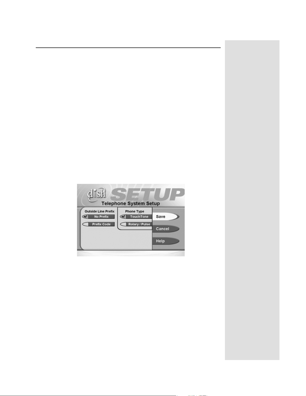
You must also set up your receiver for your telephone system (touchtone or
rotary/pulse), and set a telephone number prefix, if you need a prefix to make an
outside call.
1. Press the
MENU button.
2. Select the Installation and Setup option.
3. Select the Telephone System
Setup
menu.
4. Select the Touch Tone or the Rotary/Pulse
list.
5. If you do not need a dialing prefix to call outside your premises, select the
Save option, and stop here. If you do need to set a prefix to dial outside
your premises (for example, dial 9 to get an outside line), go to step 5.
HONE jack to an active telephone connection.
option to display the Telephone System
option in the Phone Type
Tip: If yo u h av e
the receiver connected to a Digita l S u b s crib e r
Line (DSL) on
th e phone line,
you may need to
install a DS L filter between the
receiver and the
te lep h o n e jac k .
You can obtain
th e filte r fro m
your DSL provider.
Page 19
Page 12
Chapter 2
Receiver Description and Installation
Note: Usually, you need a telephone number prefix only for business
installations. For most residential installations, all you need to do is set
the telephone system type.
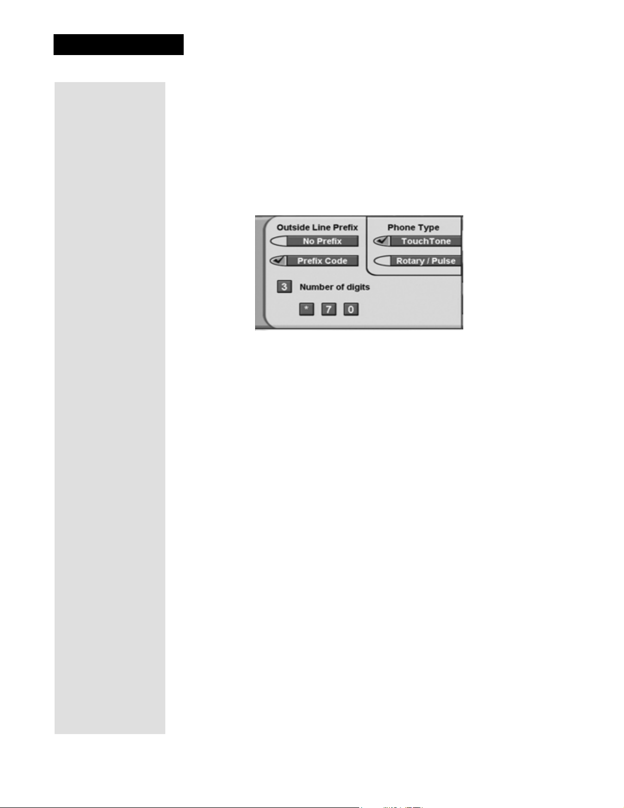
6. Move the highlight to the Outside Line Prefix list. Press the
SELECT button to select the highlighted option.
7. Select the
of boxes (highlighting the first box) where you must enter the digits.
Use the Number Pad to enter the prefix code. As you enter each number, the highlight moves to the next box.
Prefix Code option. The receiver displays the same number
8. When you have completed entering all of your numbers, the
Telephone System Setup screen will return. Select the
option to save the settings.
Save
Page 20
 Loading...