

Page 1
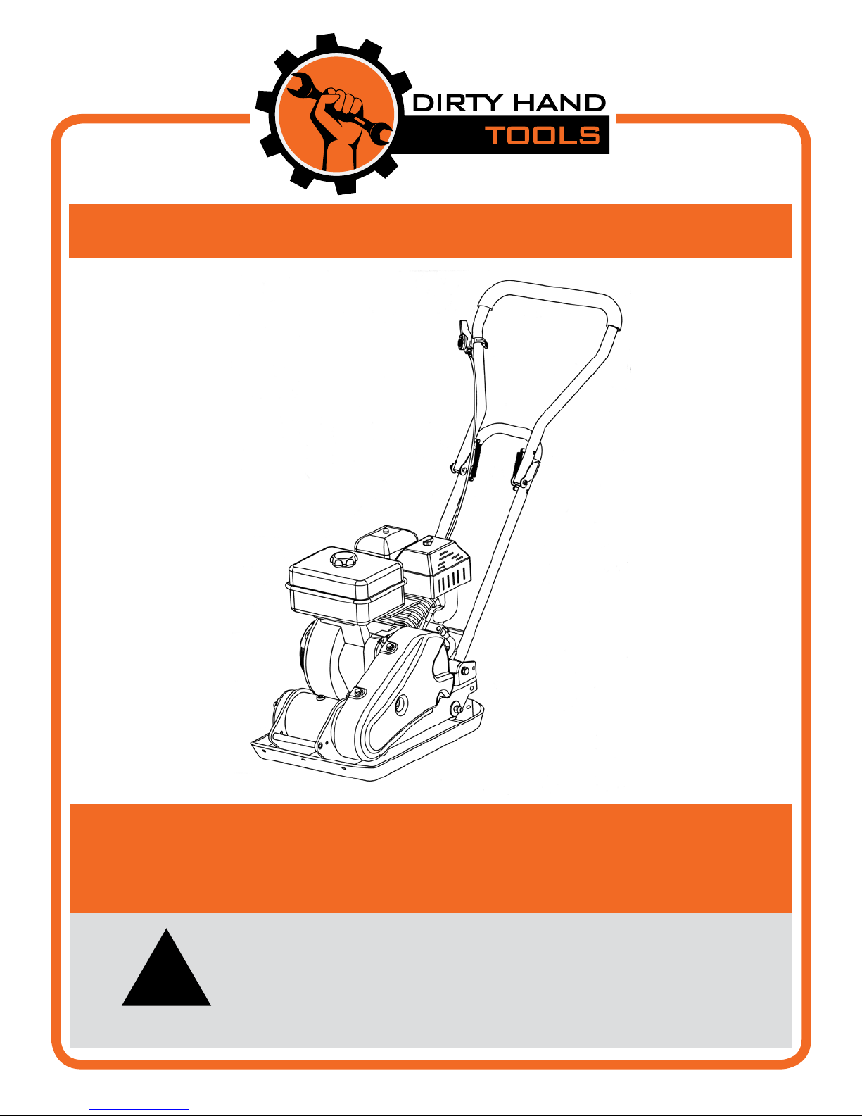
Vibratory Plate Compactor
MODELS # 104001 and #104950
Operation Manual
is safety alert symbol identies important safety messages in
this manual. Failure to follow this important safety information
!
may result in serious injury or death.
Part # 104951 Rev. D
Page 2

For Service or Questions
Call 1-877-487-8275
720-287-5182
www.dirtyhandtools.com
Dirty Hand Tools® is a brand of
1100 W 120th Ave, Suite 600
Westminster, CO 80234 • 720-287-5182
Page 3

Table of Contents
Important Safety Information
Intended Use ..............................................................................4
Personal Protective Equipment ..................................................4
General Safety ............................................................................5
Safety Decals ..............................................................................6
Unpacking .....................................................................................7
Installing the Air Filter (Model 104950) .....................................7
Overview .......................................................................................8
Handlebar Assembly ...................................................................9
Wheel Assembly..........................................................................9
Paving Pad Assembly.................................................................10
Operating Precautions ................................................................11
Operating Instructions
Preparation for Operation .........................................................12
Starting the Engine ...................................................................13
Compacting Tips .......................................................................14
Maintenance
Engine Maintenance .................................................................17
Exciter Lubrication ...................................................................17
Storage .........................................................................................18
Troubleshooting ..........................................................................19
Warranty & Specications ......................................... Back Cover
3
Page 4
Important Safety Information
!
WARNING
WARNING: Read and thoroughly understand all instructions
and safety information before assembling or operating this
equipment. Failure to do so may cause serious injury or death. Do
not allow anyone to operate this equipment who has not read this
manual. As with all power equipment, a vibratory plate compactor
can be dangerous if assembled or used improperly. Do not operate
this plate compactor if you have doubts or questions concerning
safe operation.
Call our customer service department at 720-287-5182,
1-877-487-8275, or visit www.dirtyhandtools.com if you have any
questions or concerns about the safe operation of this equipment.
Intended Use
Do Not Use the plate compactor for any purpose other than
compacting soil, gravel, sand or other crushed aggregate for which
it was specifically designed. Any other use is unauthorized and may
result in serious injury or death.
!
CAUTION
is compactor is not intended for use on cohesive soils
such as clay or hard surfaces such as concrete.
Personal Protective Equipment
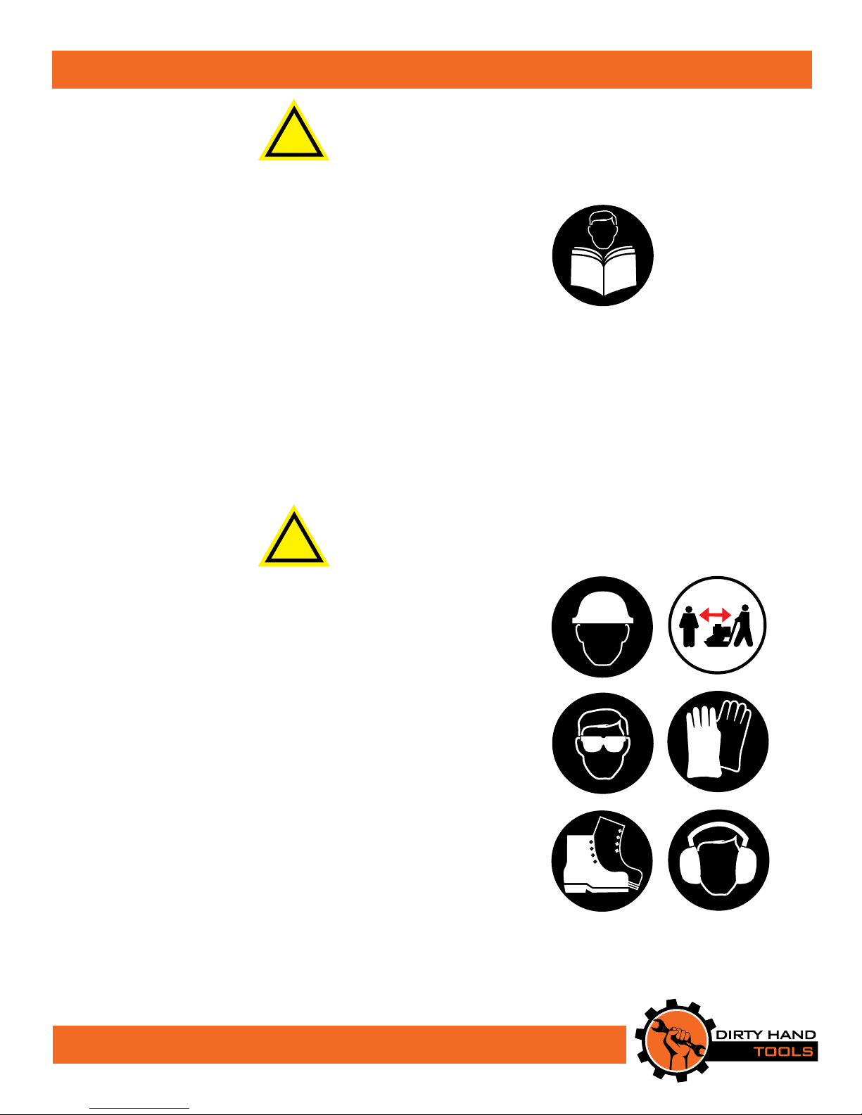
When operating this plate compactor it is essential that you wear
safety gear including goggles or safety glasses, steel toed shoes and
tight fitting gloves (no loose cuffs or draw strings). Always wear ear
plugs or sound deafening headphones to protect against hearing
loss when operating this equipment. Always wear sturdy footwear.
Never wear sandals, sneakers or open shoes, and never operate the
plate compactor with bare feet. Do not wear loose clothing that
might get caught in moving parts. Do not operate near bystanders.
CALIFORNIA PROPOSITION 65 WARNING
Engine exhaust, some of its constituents and certain product components contain or emit chemicals known to the state of California
to cause cancer and birth defects or other reproductive harm.
4
Page 5
Important Safety Information
General Safety
Failure to follow warnings, cautions, assembly and operation
instructions in the Operation Manual may result in serious injury
or death.
!
DANGER
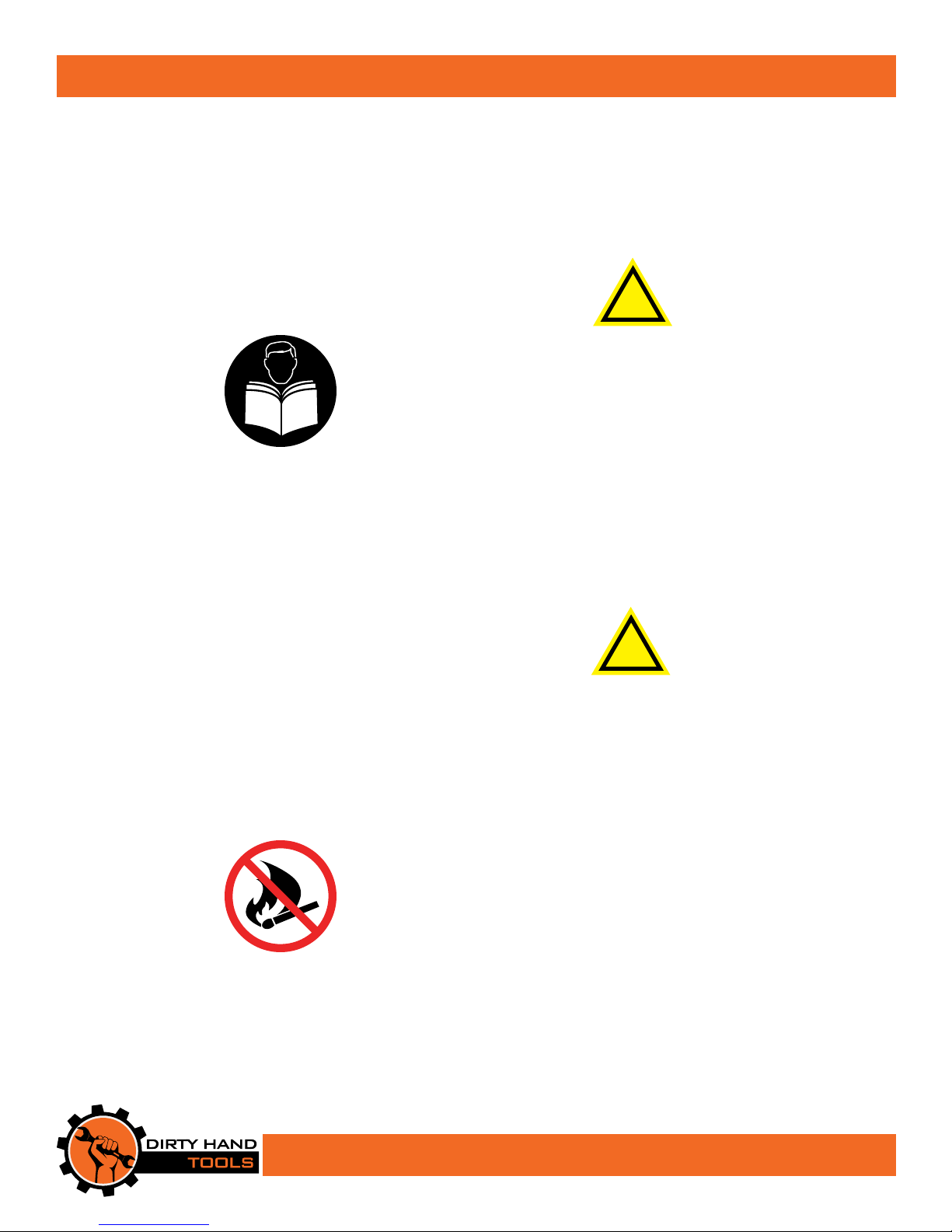
READ THE OPERATION MANUAL BEFORE
OPERATION.
• Do not permit children to operate this equipment at any time.
• Do not permit others that have not read and understood the
complete Operation Manual to operate this equipment.
• Keep all people and pets a minimum of 10 feet away from the
work area when operating this plate compactor.
• Do not operate the plate compactor when under the influence of
alcohol, drugs or medication.
• Do not allow a person who is tired or otherwise impaired or not
completely alert to operate the plate compactor.
!
DANGER
CAREFULLY INSPECT THE AREA TO BE
COMPACTED AND REMOVE ALL FOREIGN
OBJECTS.
Do not use above underground water lines, gas lines, electric cables,
or pipes. Do not operate the plate compactor in soil with large
rocks and foreign objects which can damage the equipment.
• Handle fuel with care; it is highly flammable. Use an approved
fuel container. Never add fuel to a running engine or hot engine.
• Fill fuel tank outdoors with extreme care. Never ll fuel tank
indoors.
• Replace gasoline cap securely and clean up spilled fuel before
restarting.
• Never attempt to make any adjustments while the engine is
running.
5
Page 6
Important Safety Information
Safety Decals
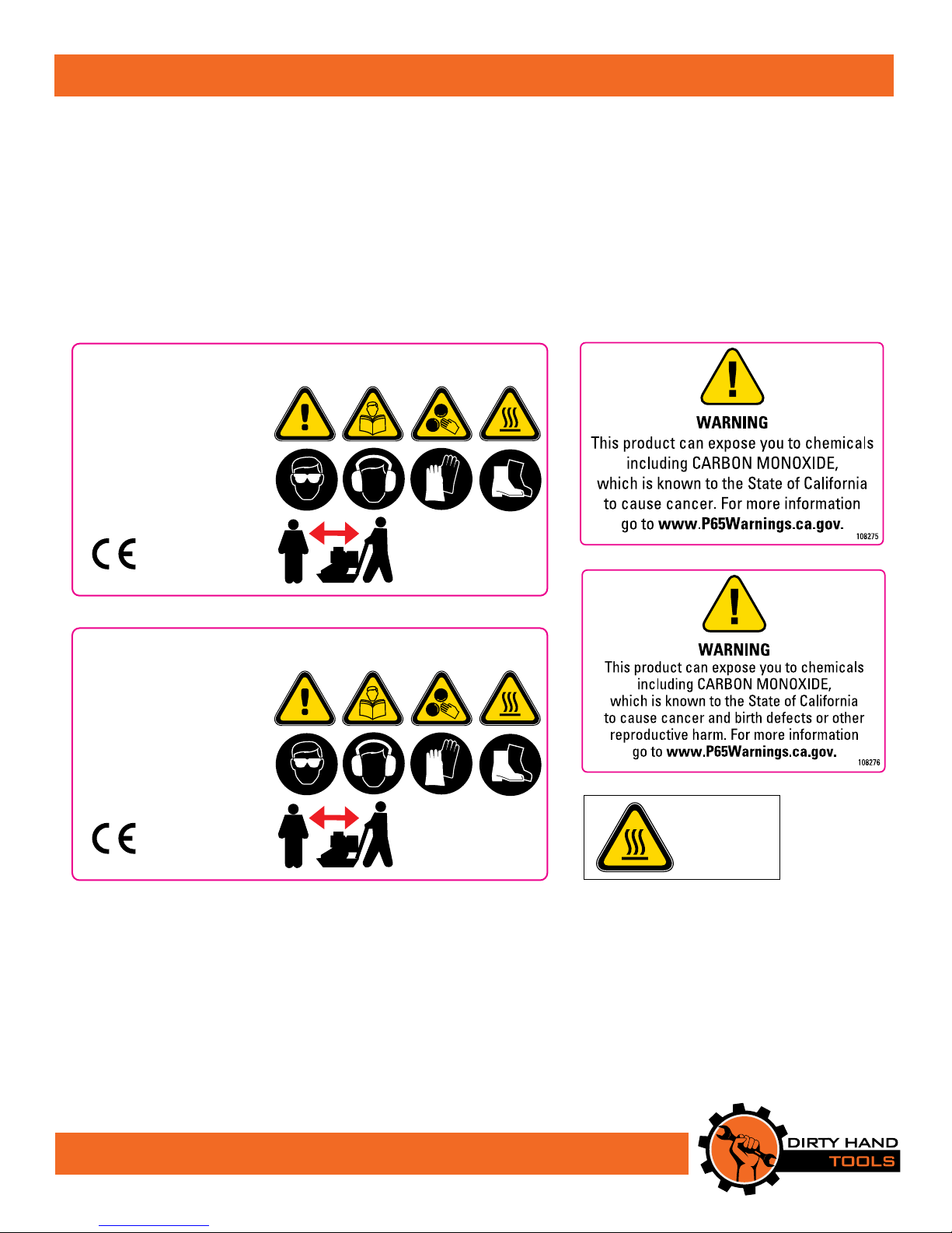
Safety labels on the plate compactor are to remind you of
important information while you are operating the unit.
Make sure all safety warning decals are attached and in
readable condition. Replace missing or defaced decals. Contact
Dirty Hand Tools at 1-877-487-8275 for replacement decals.
VIBRATORY PLATE COMPACTOR
Model No. 104001
Plate Size: 21.3” x 16.5”
Exciter Speed: 5500vpm
Centrifugal Force: 2,922 Lbs
Travel Speed: 49 ft/min
Engine: 196cc
Weight: 191.8 Lbs.
READ MANUAL
BEFORE OPERATING
WEAR GOGGLES,
BOOTS & GLOVES
104963
KEEP PEOPLE AWAY
VIBRATORY PLATE COMPACTOR
Model No. 104950
Plate Size: 19.5” x 12.6”
Exciter Speed: 5900vpm
Centrifugal Force: 1,843 Lbs
Travel Speed: 82 ft/min
Engine: 79cc
Weight: 108 Lbs.
READ MANUAL
BEFORE OPERATING
WEAR GOGGLES,
BOOTS & GLOVES
104964
KEEP PEOPLE AWAY
104897
CAUTION !
HOT SURFACE
DO NOT TOUCH
MUFFLER !
6
Page 7
Unpacking and Assembly
Your plate compactor will require some assembly. e following
instructions will help you unpack and assemble your plate compactor,
and adjust the tensioning on the v-belts.
Unpacking
Open top of carton and remove the plate compactor components.
Plate Compactor Components:
Plate Compactor chassis with engine assembly
Handlebar assembly
Folding wheel kit
Paving pad kit (Model 104001)
Air Filter, Air Filter Cover and Retaining Knob (Model 104950)
Hardware bag
Operation Manual
DO NOT ATTEMPT TO START ENGINE
BEFORE ADDING OIL TO ENGINE
e engine is shipped from the factory without oil.
You must add engine oil before starting the engine.
Use only 10/30W oil for a 4-cycle engine.
!
CAUTION
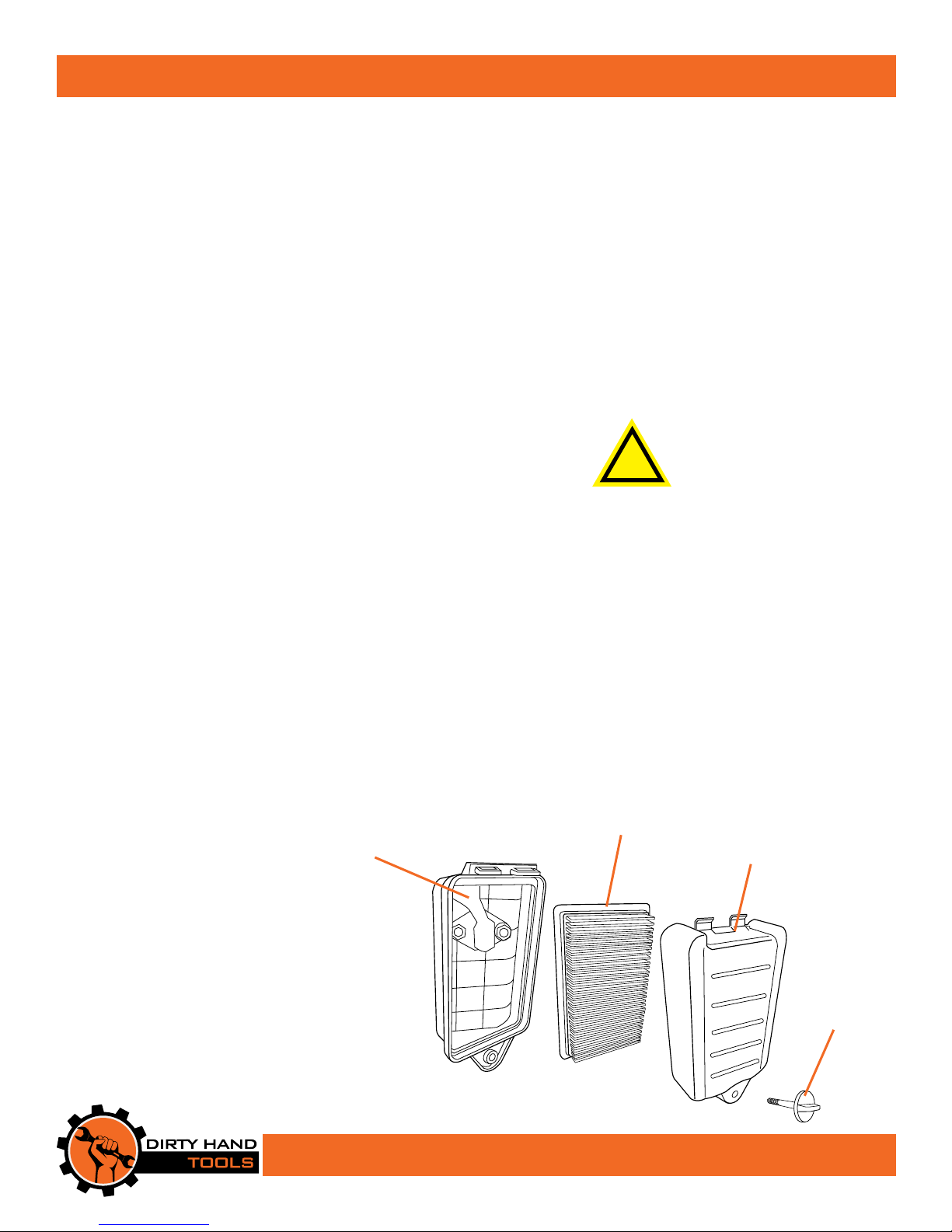
AIR FILTER
HOUSING
Installing e Air Filter (Model 104950)
Place the air lter in the air lter housing, with the ribbed side facing
the inside of the cover. Align the two tabs at the top of the air lter
cover with the two slots at the top of the housing and close. Insert the
retaining knob into the hole at the bottom of the cover and thread
into the housing until the cover is secured tightly.
AIR FILTER
AIR FILTER
COVER
RETAINING
KNOB
7
Page 8
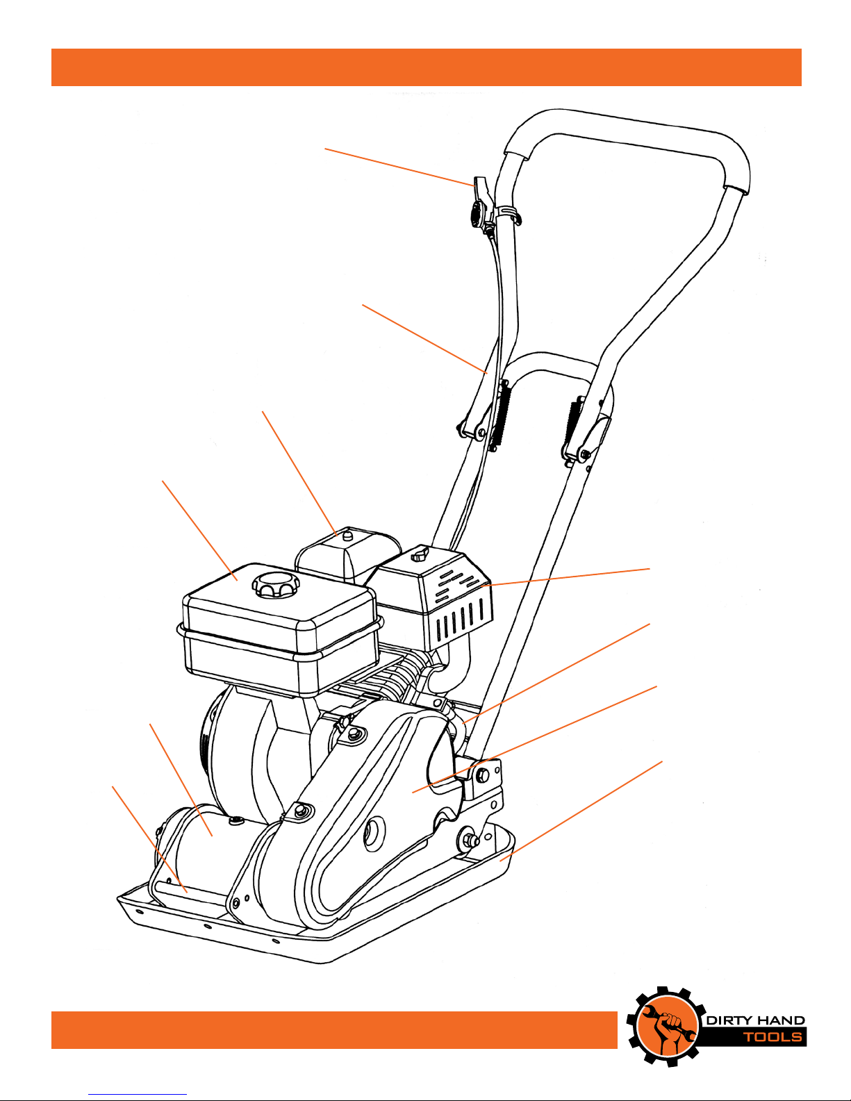
Overview of Components
THROTTLE
CONTROL
LEVER
HANDLEBAR
ASSEMBLY
AIR CLEANER
FUEL TANK
EXCITER
LIFTING
HANDLE
MUFFLER
OIL DRAIN
HOSE
BELT
GUARD
BASE
PLATE
8
Page 9
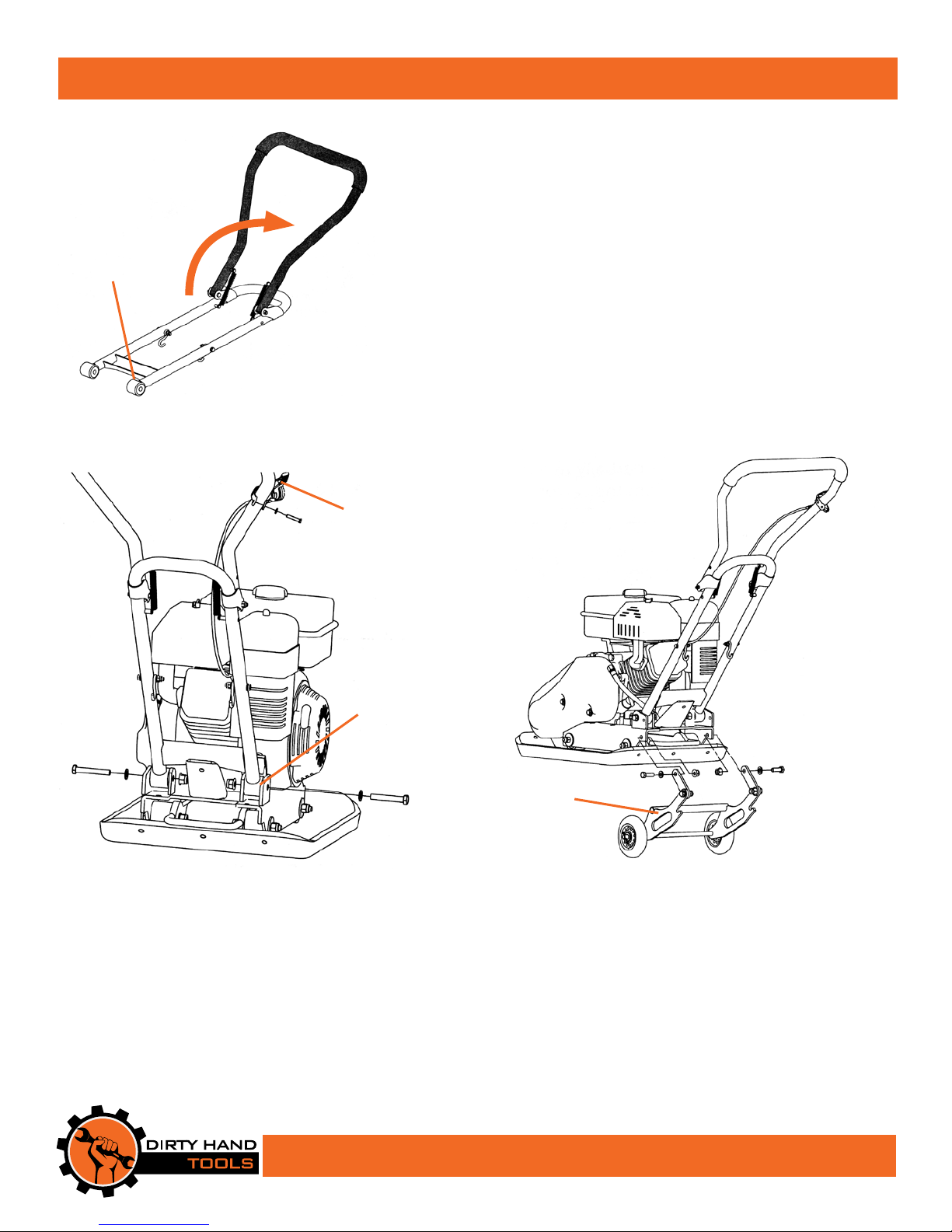
HANDLEBAR
END
Figure 1
Handlebar and Wheel Assembly
Mounting the Handlebar Assembly
1. Unfold the handlebars (see Figure 1).
2. Place the handlebar ends into the mounting channels on the engine’s
deck, carefully aligning the holes in each side (see Figure 2). Secure
the handlebar ends to the channel with a hex bolt (M10x65mm), flat
washer and locknut.
3. Position the throttle control onto the upper portion of the handlebar
and secure with a flat washer and hex bolt (M5x25mm).
Mounting the Folding Wheel Assembly
1. Position the folding wheel assembly at the rear of the plate compactor.
Line up the holes in the mounting links with the holes in the engine
deck and secure with hex bolt (M10x30mm), flat washer and lock nut
on each side (see Figure 3).
THROTTLE
CONTROL
Figure 2
MOUNTING
CHANNEL
FOLDING
WHEEL KIT
Figure 3
9
Page 10
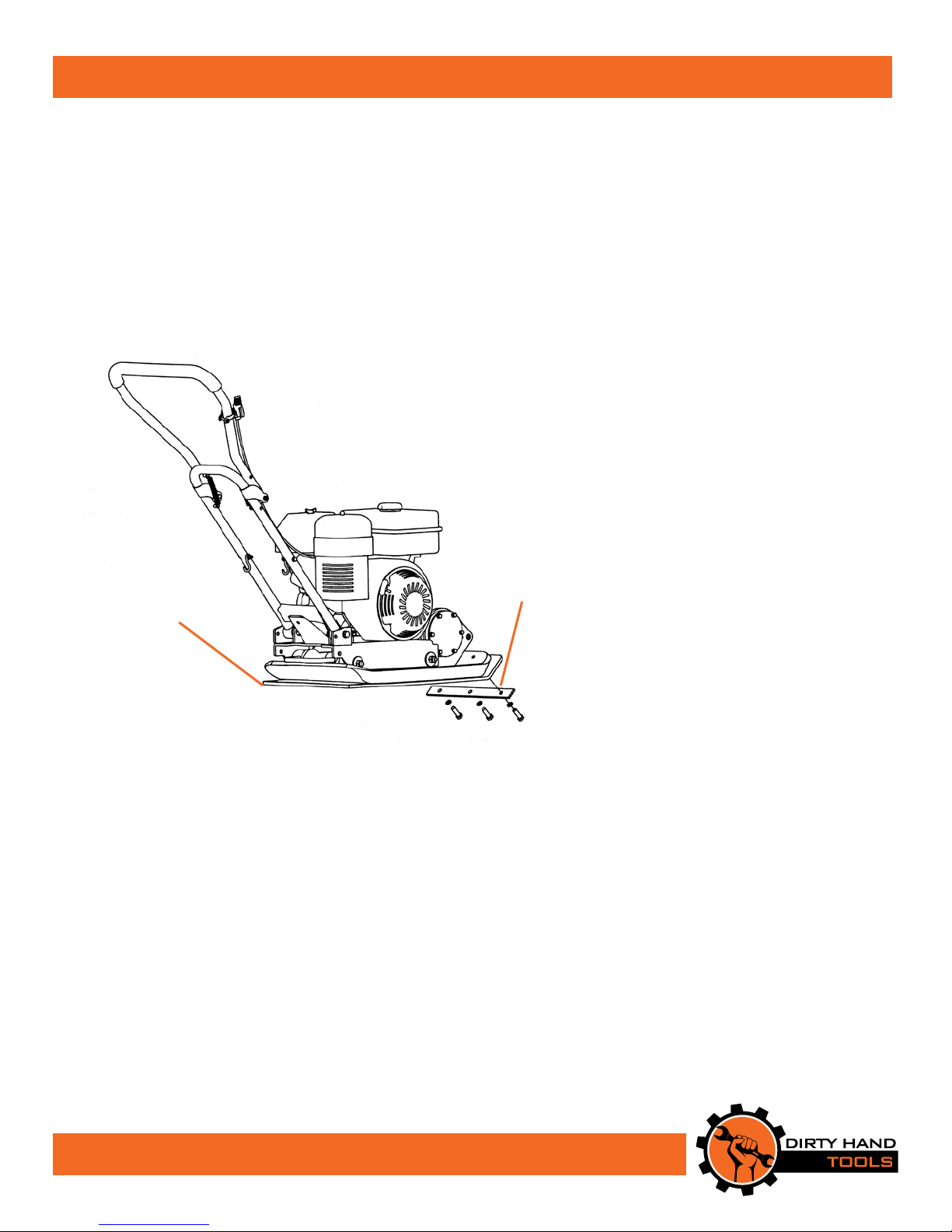
Paving Pad Assembly (Model 104001)
Paving Pad Kit
e paving pad kit should be used when compacting on concrete paving
slabs, decorative stone, brick or other material to reduce noise and
prevent scratching. (e paving pad is included with Model 104001 only).
Attaching the Paving Pad
1. Align the holes in the paving pad with the holes in the clamp plate
on the compactor’s base plate. Secure with hex bolts (M10x30mm) and
flat washers in three places (see Figure 4).
PAVING
PAD
CLAMP
PLATE
Figure 4
10
Page 11

Operating Precautions
!
CAUTION
READ, UNDERSTAND AND FOLLOW ALL OF THE
PRECAUTIONS BELOW.
Always check equipment condition before starting the engine.
• Never start or run the plate compactor in an enclosed area.
• Keep hands and feet away from the base plate during operation.
• Always operate the plate compactor from the rear gripping the
handlebars with both hands.
• Never lift or carry the plate compactor with the engine running.
• Engine muer will be hot from operation. Do not touch it with bare
skin or a severe burn may result.
• If the unit vibrates abnormally, stop the engine and check immediately
for the cause. Abnormal vibration is an indication of a potential problem.
• Never operate the machine on slippery surfaces.
• Use only attachments and accessories approved by the manufacturer.
• Never operate the plate compactor without good visibility or adequate
light.
• Take precautions when leaving the machine unattended. Disengage
all control levers, stop the engine, wait for all moving parts to stop.
• Shut o the engine when leaving the operating position for any
reason. Wait for all moving parts to stop.
!
WARNING
OPERATION OF A PLATE COMPACTOR CAN RESULT IN
FOREIGN OBJECTS BEING THROWN. ALWAYS WEAR
SAFETY GLASSES DURING OPERATION.
11
Page 12
Operating Instructions
H
L
Preparation for Operation
!
WARNING
UNIT IS SHIPPED WITHOUT OIL IN THE ENGINE.
ADD OIL BEFORE STARTING THE ENGINE
Check the oil level before each operation.
Fill Engine with Oil
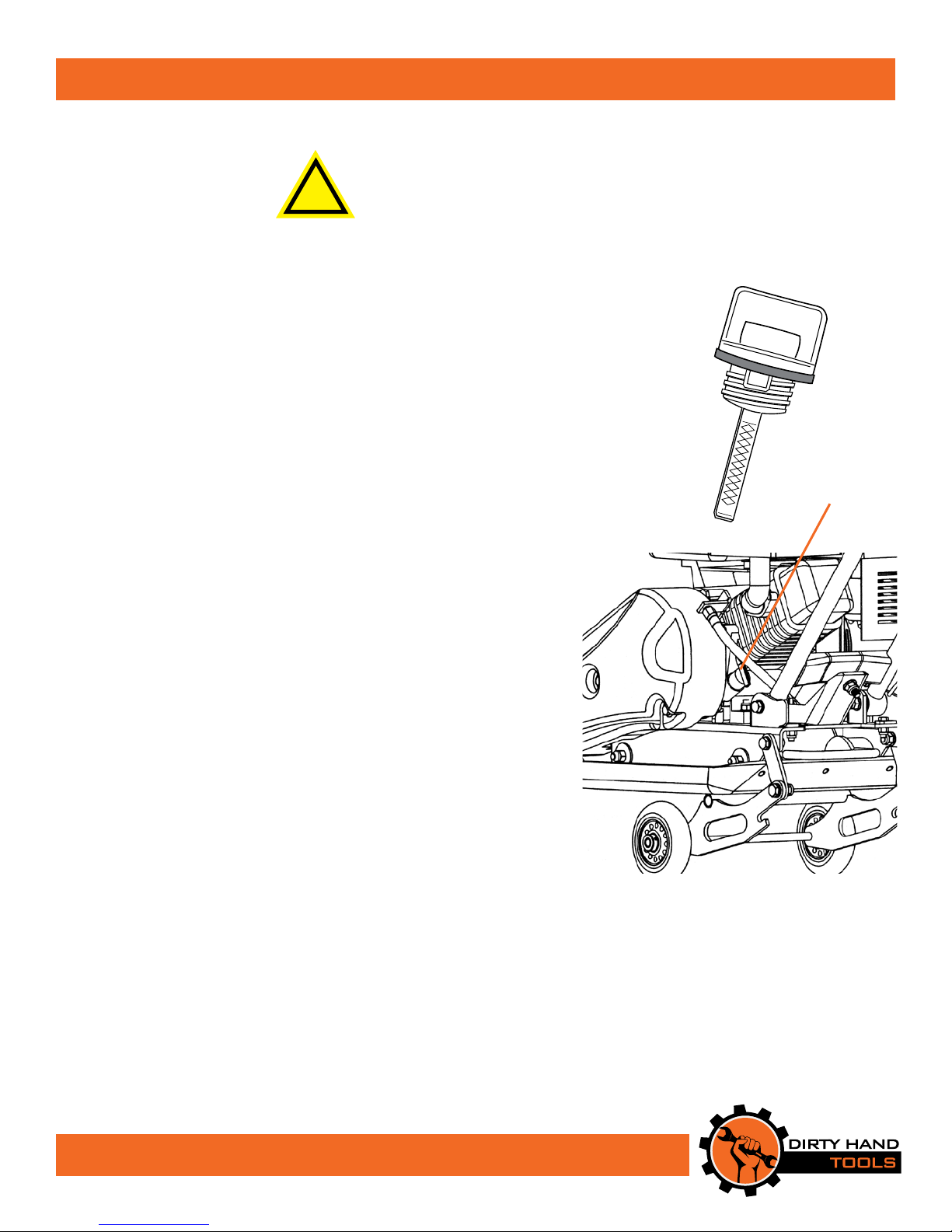
1. Add oil according to engine manual. Do not overll. Use
SAE30 engine oil. Do not mix oil with gasoline. Oil level
must be full. Check the oil level by removing the dipstick (see
Figure 5).
Pre-Start Inspection
1. Make sure all nuts, bolts and hardware are in place and secure.
2. Check oil level.
3. Inspect air cleaner (see engine manual). Clean or replace as
needed.
4. Check fuel supply. Fill the fuel tank no closer than 1 inch
from top of tank to provide space for expansion.
5. Examine underneath and around engine for oil or fuel leaks.
6. Inspect fuel hoses for tightness and fuel seepage.
7. Look for signs of engine damage.
8. Remove excessive debris from muer area and recoil starter.
OIL
DIPSTICK
12
Figure 5
Page 13
Starting the Engine
WARNING
!
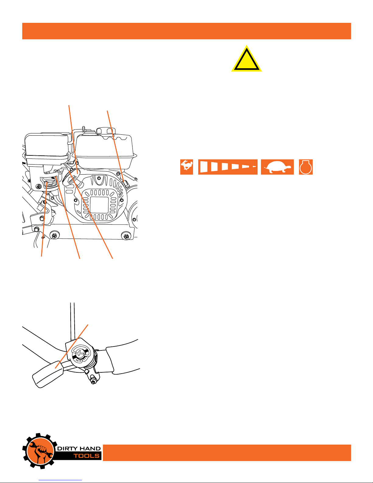
RECOIL
STARTER
FUEL VALVE
(Model 104001)
CHOKE
ENGINE
ON/OFF
SWITCH
THROTTLE
NEVER FILL THE FUEL TANK ON A HOT ENGINE
Start-Up
e controls required to start and run the plate compactor are
located on the engine and the handlebars. A detailed description of
engine operation and precautions is available in the engine operation
manual.
START
START
ENGINE
FULL
THROTTLE
LOW
THROTTLE
STOP
STOP
ENGINE
Starting a Cold Engine
1. Turn the engine ON/OFF switch to ON (see Figure 6).
2. Move choke lever to the closed (full choke) position.
3. Move fuel valve to open position (Model 104001).
4. Move throttle control lever to low (see Figure 7).
5. Pull recoil handle slowly one time and allow to return normally.
6. Pull recoil handle out rapidly, and allow rope to return normally.
7. When engine starts, gradually move choke lever to “no choke”
position and increase throttle speed towards full throttle.
Figure 6
D
Y
C
L
Figure 7
THROTTLE
CONTROL
LEVER
H
Restarting A Warm Engine
Restarting an engine that is already warm from previous running does
not normally require use of the choke. Adjust throttle speed to “high”
for best plate compactor action.
Idle Speed
Use the “low” position on the throttle lever to reduce stress on the
engine when compacting is not being performed. Lowering the
engine speed to “idle” will help extend the life of the engine as well as
conserve fuel and reduce the noise level of the equipment.
Operating Speed
For normal compacting, set the throttle lever to “fast”.
Shutting Down
To stop the engine move the engine ON/OFF switch to the OFF
position.
13
Page 14

Operation
!
WARNING
DO NOT OPERATE ON CONCRETE OR EXTREMELY
COMPACTED SURFACES WHICH CAUSE THE
COMPACTOR TO JUMP RATHER THAN VIBRATE
CAUSING POTENTIAL DAMAGE
TO THE PLATE OR ENGINE.
1. Start the engine.
2. Move the throttle control to fast.
3. e plate compactor will vibrate and move forwards.
4. Set the throttle to the slow or idle position when not compacting
to reduce equipment stress and preserve machine life.
5. To turn the plate compactor o, move the throttle lever to the
slow position, allowing the engine to idle for a few seconds and
then switch the engine to o.
Running the engine at lower speeds results in decreased
compaction, wear to the machine and operator fatigue.
Compacting Tips
e key to successful compacting is to allow the machine to do the
work. e operator should guide the machine, but not bear down
on the handlebar or use unnecessary force.
• Compacting will vary with ground conditions, material being
compacted and slope of surface.
• On uneven surfaces it may be necessary to apply light forward
pressure on the handlebars in order to help propel the machine
forward.
• Hold on rmly to the handlebars to control sudden lurches.
• Attach the plate pad when compacting paving stones or similar
material to avoid chipping or grinding of the surface.
• Soil conditions may be damp, but allow wet soil to dry out before
compacting. If soil is excessively dry, raising dust clouds when
compacting, sprinkle surface with water before compacting.
• A number of passes may be necessary to reach the desired
compaction level. Maximum compaction will be reached when the
machine constantly kicks back.
Do not stop the machine by moving the choke, which can cause
engine backre or damage.
14
Page 15

Maintenance
!
WARNING
BEFORE PERFORMING ANY MAINTENANCE
TURN OFF ENGINE, DETACH SPARK PLUG WIRE
AND ALLOW ENGINE TO COOL DOWN
• Keep plate compactor, safety shields and covers, attachments, and
accessories in safe working condition.
• To prevent accidental starting, always disconnect and secure the
spark plug wire from the spark plug before maintenance.
• Never run the engine indoors. Exhaust fumes are toxic.
• Always allow muffler to cool before filling fuel tank.
Engine Maintenance
Refer to the engine manual included in your parts packet for
detailed information on engine maintenance. Your engine manual
provides detailed information and a schedule for performing the
following:
1. Check oil level before each use and after 8 hours of operation.
2. Change oil after first 5-8 hours of operation. Change oil while
engine is warm. Refill with new oil of recommended grade.
4. Check spark plug yearly or every 100 hours of operation.
5. Service air cleaner.
6. Keep engine and parts clean.
7. Check engine and equipment often for loose nuts and bolts.
15
Page 16
Maintenance
Checking the V-Belts
V-Belts must be in good condition and tensioned properly to
ensure maximum performance of the plate compactor.
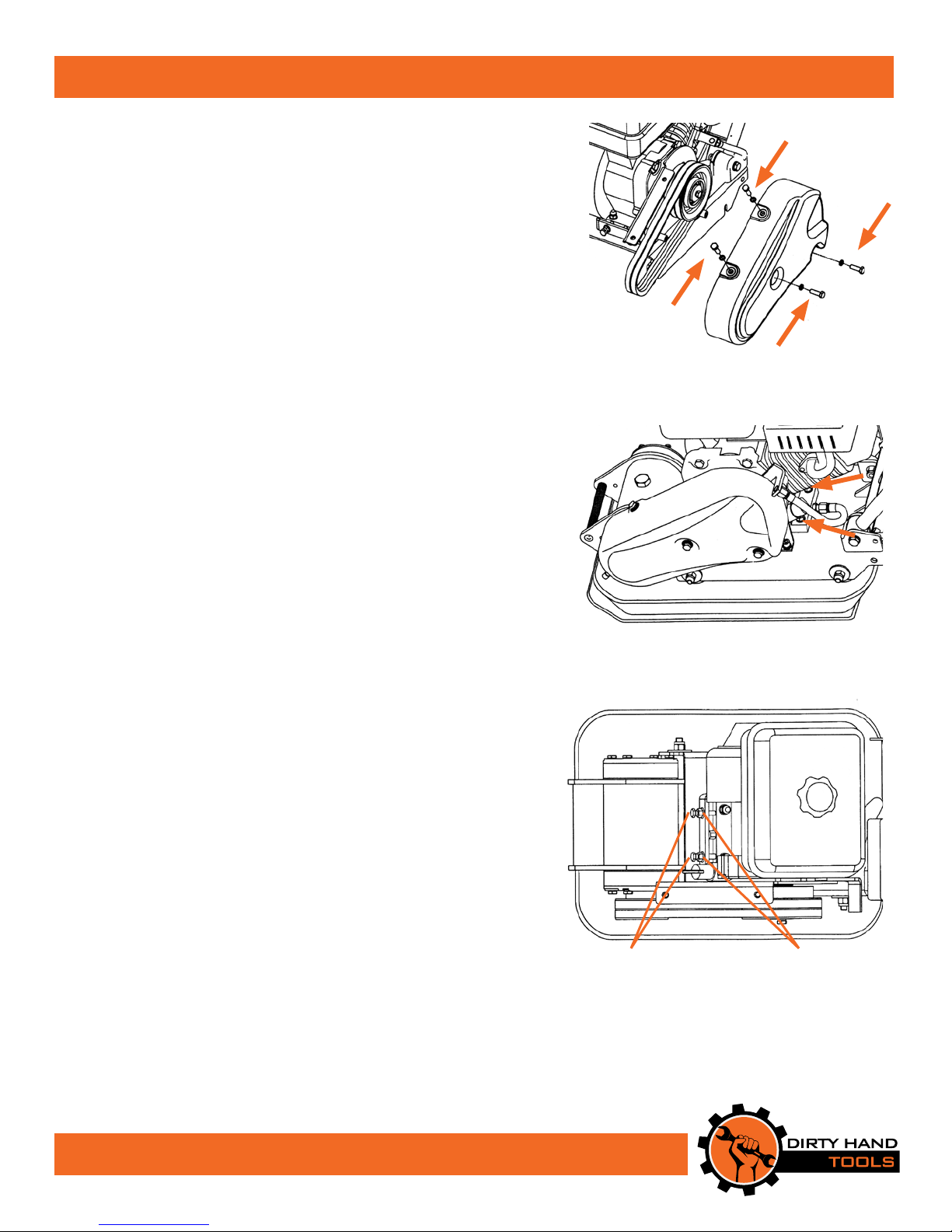
1. Remove the 4 hex bolts that secure the belt guard to access
the v-belts (see Figure 8).
2. Check the condition of the v-belts. If there is signs of
cracking, fraying or glazing, replace the belts as soon as
possible.
3. Check the belt tension by pressing on the center of the belt
length. e normal deflection on each side should be 3/8”
(9mm) - 1/2” (13mm) while applying moderate pressure
with thumb or finger.
Tensioning the V-Belts
1. Loosen 4 engine mount bolts, 2 on each end of the engine
block, just enough to move the engine slightly, but do not
remove the bolts entirely (see Figure 9).
2. Loosen the jam nuts leaving enough space between the nut
and the bracket (see Figure 10).
3. Push the engine toward the back of the plate by turning the
adjustment bolts to remove any slack in the v-belts.
4. When the v-belts are tensioned correctly, there should be 3/8”
(9mm) to 1/2” (13mm) of movement when the belt is pressed
rmly in the center of the belt length. If the adjustment bolts
can not be adjusted enough to increase the belt tension, then
the belts should be replaced.
5. Tighten the jam nuts against the bracket and tighten the
engine bolts.
6. Replace the belt guard.
Figure 8
Figure 9
Note: When adjusting the belts, make sure that the clutch
pulley and the exciter pulley are in alignment.
16
ADJUSTMENT
BOLTS
JAM
NUTS
Figure 10
Page 17
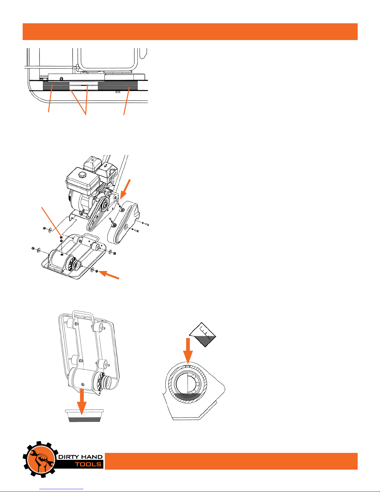
EXCITER
PULLEY
DRAIN
PLUG
V-BELTS
Figure 11
Figure 12
CLUTCH
PULLEY
PLACES
4
PLACES
Maintenance
Replacing the V-Belts
1. Loosen 4 engine mount bolts on the plate compactor just enough
to move the engine slightly, but do not remove the bolts entirely
(see Figure 9).
2. Loosen the jam nuts and bolts (see Figure 10).
3. Push the engine toward the front of the plate and slip the v-belts
o of the pulleys (see Figure 11).
4. Install new belts. It is best to replace both belts even if only one
shows wear.
5. Move the engine back and test the belt tension.
5. Tighten the jam nuts against the bracket and tighten the engine
bolts.
6. Replace the belt guard.
4
Exciter Lubrication
e exciter housing is pre-filled with automatic transmission fluid
(Dextron III or equivalent) by the manufacturer. e fluid should
be changed every 200 hours of operation.
1. Let the exciter cool before attempting to change the fluid.
2. Remove the belt guard and v-belts (see Figures 8, 9 & 11).
3. Remove bolts that secure the deck to the housing (see Figure 12).
4. Lift the deck and engine up and detach from the housing.
5. Remove the drain plug from the top of the exciter housing. Tilt
upside down so fluid drains (see Figure 13).
6. Return plate to upright position.
7. Fill exciter with 2.70 fluid ounces/80ml (2.0 fluid ounces/60ml
for the Model 104950) of automatic transmission fluid, Dextron
III or equivalent, (see Figure 14).
8. Apply pipe sealant to drain plug and reinstall.
9. Reattach the deck and engine to the plate housing. Reattach the
v-belts and belt cover.
Figure 13
Figure 14
17
Page 18
Storage
!
WARNING
DRAIN FLUIDS BEFORE LONG TERM STORAGE
Drain fuel outdoors away from any ignition sources.
Use only approved fuel containers.
Never store equipment with gasoline in the tank inside of a
closed building where fumes may reach an open flame or spark.
Allow the engine to cool before storing in any building.
Prepare for Storage
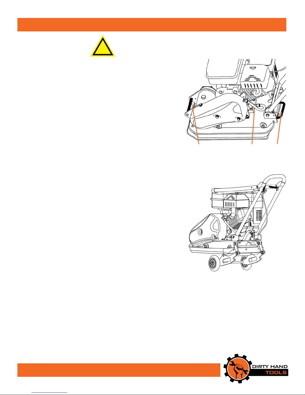
Follow the steps below to prepare your plate compactor for storage.
Read your engine manual for detailed instructions on preparing the
engine for storage.
1. Run the engine until the fuel is consumed.
2. Allow the engine to cool down. While the engine is still warm,
drain the oil by detaching the flexible oil line hose, tipping the
plate compactor slightly on its side and draining the oil into an
approved container (see Figure 15).
3. Detach the spark plug wire.
4. For more compact storage, fold the upper handlebars assembly
down (see Figure 16).
LIFT
HANDLE
OIL DRAIN
Figure 15
HOSE
LIFT
HANDLE
For Lifting and Transporting
1. Always allow the engine to cool down before transporting or
before short term storage. Use the handles on the front and rear
of the plate compactor to lift (see Figure 15).
Figure 16
18
Page 19
Troubleshooting
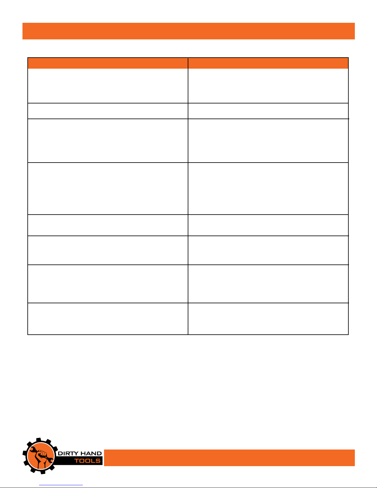
PROBLEM SOLUTION
Engine will not start • Add gas to gas tank.
• Connect spark plug wire to spark plug
• Fuel valve must be open
• rottle must be positioned at choke for a cold start
Engine runs rough, oods during operation • Clean or replace air cleaner
Engine is hard to start • Drain old fuel and replace with fresh. Use gas
stabilizer at end of season
• Make sure spark plug wire is securely attached to
spark plug
• rottle is not in proper start position
Engine misses or lacks power • Remove and clean fuel tank
• Clean or replace air cleaner
• Improper carburetor adjustment, take to authorized
engine service center
• Check and replace spark plug and adjust gap
• Drain and rell gas tank and carburetor
Engine will not stop when throttle control • See engine manual to check and adjust the
is positioned at stop throttle or remove any debris blocking the linkage
Soil is dicult to compact • Soil is too dry. Add moisture to the ground by lightly
sprinkling water with garden hose, then allow the
surface to dry
Plate compactor is dicult to control when running • Engine speed is too high. Adjust the engine’s throttle
(machine jumps or kicks back) • e material to be compacted is too hard or dense
• e material that is being compacted has reached
maximum level of compactness
Poor compaction of material • e engine throttle is set too low. Adjust the throttle
and allow several passes to reach maximum level of
compactness
19
Page 20

Warranty & Specications
IMPORTANT NOTICE
We, the manufacturer, reserve the right to change the product and/
or specifications in this manual without notification. e manual is for
information usage only and the pictures and drawings depicted herein are
for reference only.
Warranty Repair and Service
Do not return this product to the store for warranty issues or repair. Call
our customer service department at 720-287-5182, 1-877-487-8275, or
visit www.dirtyhandtools.com for the location of the nearest service center.
Record the information below for future reference.
Model No.
Serial No.
Date of Purchase
Place of Purchase
Specications
SKU/Part No. 104001 104950
Description Vibratory Plate Compactor Vibratory Plate Compactor
Engine 196cc Engine*, EPA/50 State Approved 79cc Engine*, EPA/50 State Approved
Engine Oil Capacity** 0.63 quarts (0.6 liters) 0.37 quarts (0.35 liters)
Operating Speed 3600 RPM 3600 RPM
Plate Size 21.26” L x 16”.54 W (540mm x 420mm) 19.5” L x 12.6” W (495mm x 320mm)
Exciter Speed 5500 VPM 5900 VPM
Exciter Capacity 2.70 fluid ounces (80ml) transmission fluid 2.0 fluid ounces (60ml) transmission fluid
Centrifugal Force 2,922 Lbs. 1,843 Lbs.
Travel Speed 49 feet/minute (15m/min) 82 feet/minute (25m/min)
Dimensions 48”L x 21.25”W x 42.25”H (including handlebar) 48”L x 21.25”W x 42.25”H (including handlebar)
Shipping Weight 191.8 Lbs. (87kg) 108 Lbs. (49kg)
Warranty 2 Year Limited Warranty 2 Year Limited Warranty
*As rated by engine manufacturer
** Not included, shipped without engine oil
Dirty Hand Tools® is a brand of
1100 W 120th Ave., Suite 600
Westminster, CO 80234 • 720-287-5182
For Service or Questions
Call 1-877-487-8275
720-287-5182
www.dirtyhandtools.com
 Loading...