

Page 1
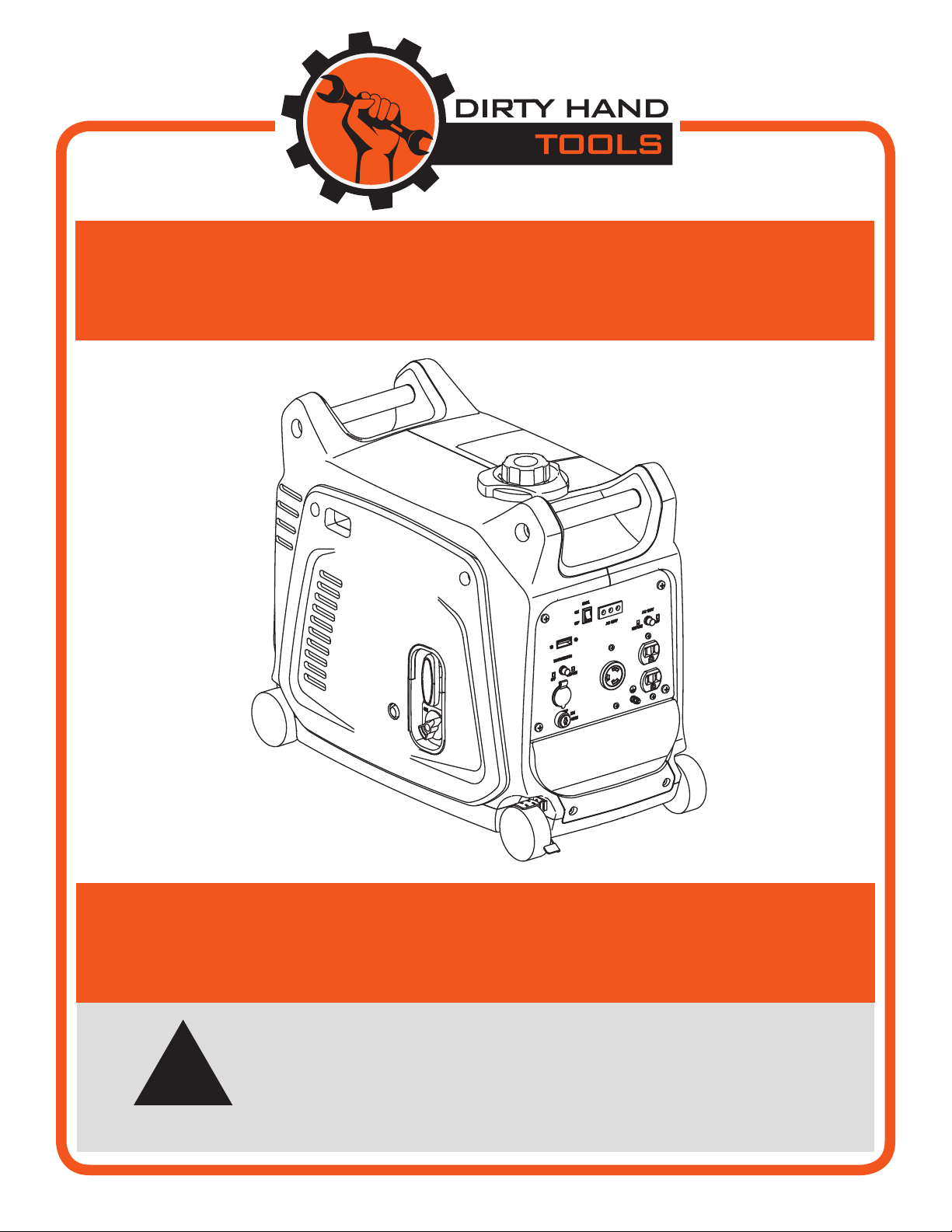
3200Watts
PORTABLE INVERTER GENERATOR
!
MODEL #104612
Operation Manual
is safety alert symbol identies important safety messages in
this manual. Failure to follow this important safety information
may result in serious injury or death.
Part # 104829
Page 2

For Service or Questions
Call 1-877-487-8275
720-287-5182
www.dirtyhandtools.com
Dirty Hand Tools® is a brand of
1100 W 120th Ave, Suite 600
Westminster, CO 80234 • 720-287-5182
Page 3

Table of Contents
Important Safety Information .....................................................4
Components ...................................................................................7
Operation Precautions ....................................................................8
Operation .......................................................................................9
Maintenance .................................................................................12
Troubleshooting ...........................................................................16
Storage .........................................................................................17
Warranty and Specifications .......................................... Back Cover
3
Page 4
Important Safety Information
!
WARNING
WARNING: Read and thoroughly understand all instructions
and safety information before operating this portable power
generator. Failure to do so may cause serious injury or death.
Do not allow anyone to operate this portable power generator
who has not read this manual. As with all power equipment, a
portable power generator can be dangerous if used improperly. Do
not operate this portable power generator if you have doubts or
questions concerning safe operation.
Call our customer service department at 720-287-5182,
1-877-487-8275, or visit www.dirtyhandtools.com if you have any
questions or concerns about the safe operation of this equipment.
!
DANGER
Intended Use
Do Not Use the portable power generator for any purpose other
than for which it was designed. Any other use is unauthorized and
may result in serious injury or death.
Personal Protective Equipment
While this portable power generator operates at a relatively low
noise level, about 60 dB, you may want to wear ear plugs or noise
deafening headphones when using.
!
CAUTION
People with pacemakers should consult their physician(s) before
use. Electromagnetic fields in close proximity to a heart pacemaker
could cause pacemaker interference or pacemaker failure. Caution
is necessary when near the engine’s magneto or recoil starter.
4
Page 5
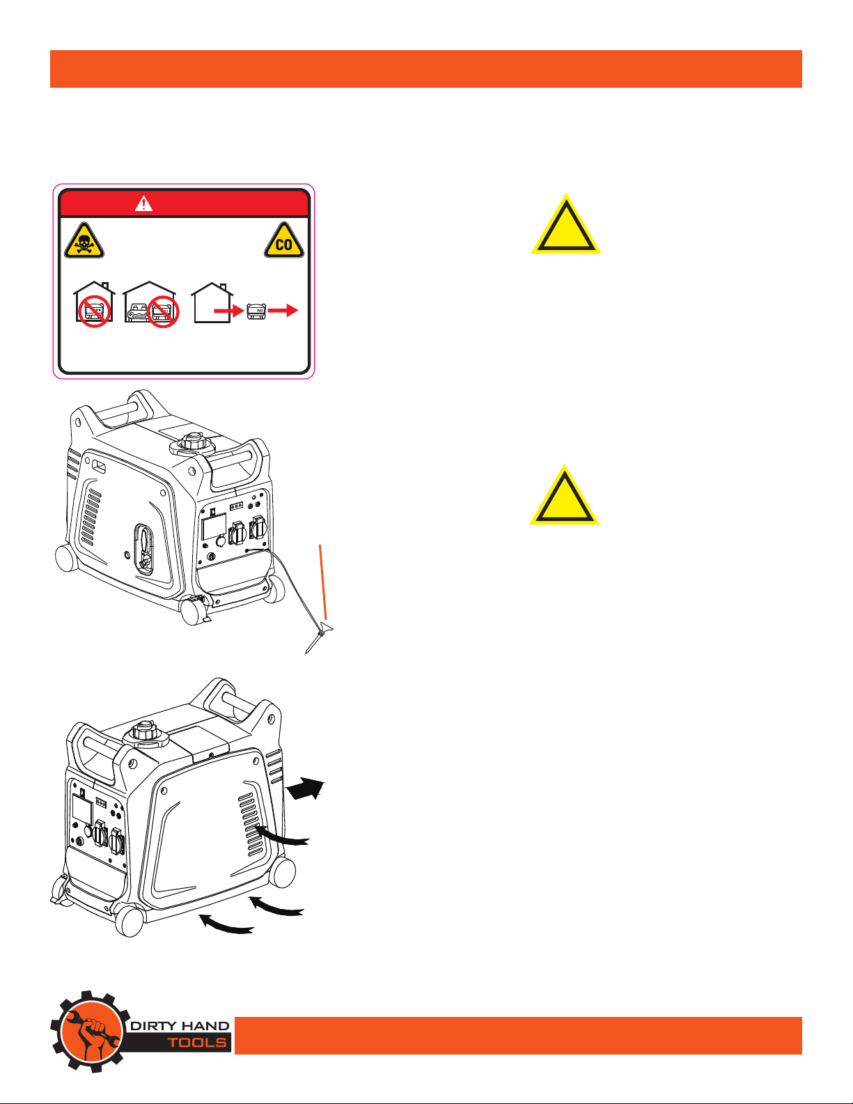
DANGER
USING A GENERATOR INDOORS
CAN KILL YOU IN MINUTES
Exhaust contains carbon monoxide
which is a poison
that you cannot see or smell.
Never use inside a house
or garage even with doors
and windows open!
Use only outside away
from windows,
doors and vents!
101119
Important Safety Information
General Safety
Failure to follow warnings, cautions, assembly and operation
instructions in the Operation Manual may result in serious injury
or death.
!
DANGER
READ THE OPERATION MANUAL BEFORE
OPERATION.
• Do not permit children to operate this equipment at any time.
Do not permit others that have not read and understood the
complete Operation Manual to operate this equipment.
• Do not operate the portable power generator when under the
influence of alcohol, drugs or medication.
• Do not allow a person who is tired or otherwise impaired or not
completely alert to operate the portable power generator.
GROUND
STAKE
!
DANGER
NEVER OPERATE INDOORS
Exhaust fumes contain Carbon Monoxide, a deadly poison.
• Attach a grounding wire and stake before starting the generator
Figure 1
(see Figure 1).
• Operate the generator on a level, flat surface in a well ventilated,
dry location, away from other equipment (see Figure 2).
• Keep all safety guards in place and in proper working order.
HOT
• Do not transport the generator with the engine running.
AIR
• Do not tilt the machine while the engine is running.
• Do not leave the generator unattended when it is running.
• Never operate the generator when exposed to rain, snow or
other moisture.
• Never touch the generator with wet hands or wet clothing.
• Operate at least 3 feet away from other equipment, walls,
buildings or anything that would block access to cool air.
• Do not connect the generator to any other power system
including other generators.
COOL
AIR
Figure 2
• Avoid touching the muffler as it may be hot.
• Always turn the engine off when refueling.
• Transport only by using the carrying handle.
5
Page 6
Important Safety Information
• Never run the engine in an enclosed area or without proper
ventilation as the exhaust from the engine contains carbon
monoxide, which is an odorless, tasteless, and deadly
poisonous gas.
• Fill the gasoline tank outdoors with the engine off and allow
the engine to cool completely.
• Do not operate the engine without an air cleaner or with the
side cover removed.
• e muer and engine become very hot with use and can
cause a severe burn; do not touch. Allow the engine to cool
before refueling, doing maintenance, or making adjustments.
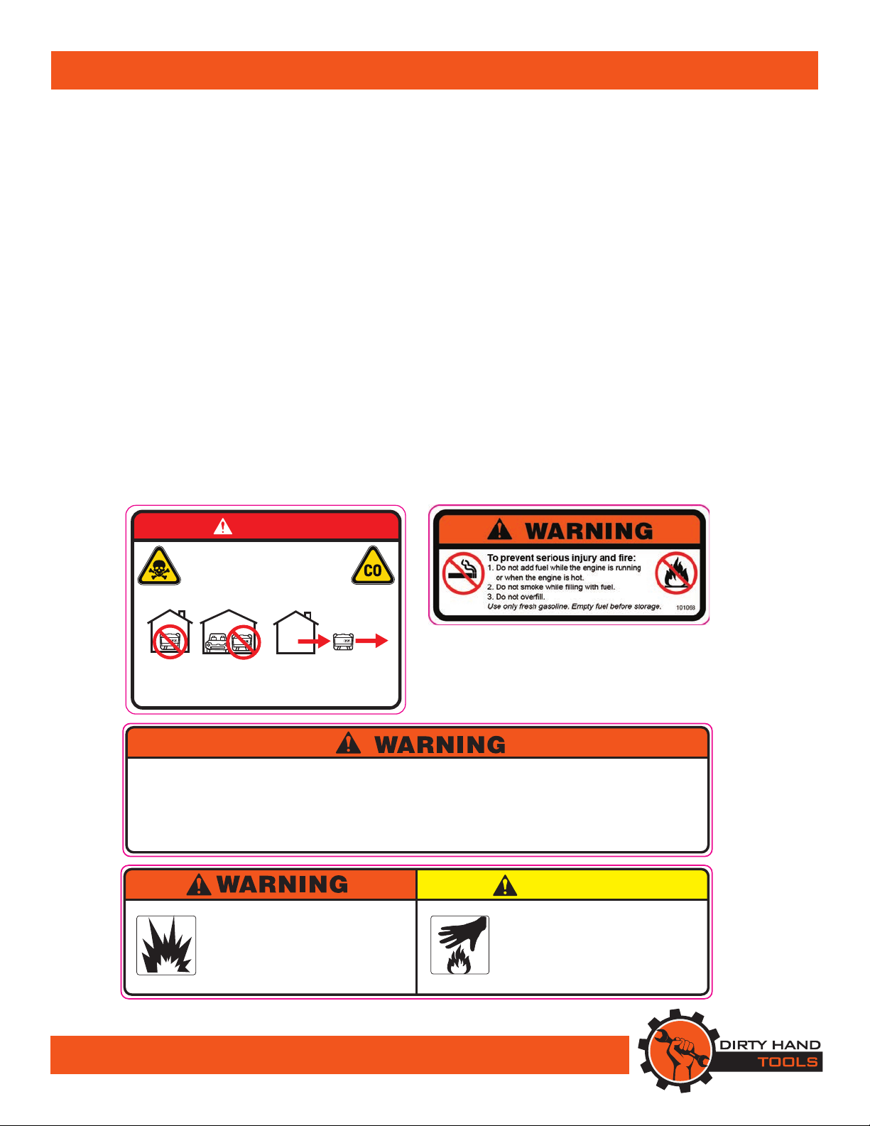
Safety Decals
Safety labels on the portable power generator are to remind
you of important information while you are operating the
unit. Make sure all safety warning decals are attached and in
readable condition. Replace missing or defaced decals. Contact
Dirty Hand Tools at 1-877-487-8275 for replacement decals.
DANGER
USING A GENERATOR INDOORS
CAN KILL YOU IN MINUTES
Exhaust contains carbon monoxide
which is a poison
that you cannot see or smell.
Never use inside a house
or garage even with doors
and windows open!
To prevent serious injury, electric shock and property damage:
1. Keep access doors on enclosures locked.
2. Have licensed electrician do all electric work including
ground connection and maintenance.
3. Keep dry.
4. Keep all guards in place and in proper working condition.
5. Wear ANSI-approved safety goggles during setup and maintenance.
6. Turn switch off and remove key after use.
To prevent serious injury:
Operation of this equipment may create
sparks that can start fires around dry
vegetation or flammable materials.
A spark arrestor may be required.
Operator should contact local fire agencies
for laws and regulations regarding fire
prevention requirements.
Use only outside away
from windows,
doors and vents!
101119
7. Read Operator’s Manual before setup or use.
8. Add engine oil before starting. Starting without oil will ruin the
engine and void warranty. Read maintenance information in
the Operator’s Manual.
9. Unconditioned electrical equipment can damage sensitive equipment.
Do not use to power sensitive electric equipment without appropriate
line conditioner sold separately.
CAUTION
HOT MUFFLER!
TO PREVENT BURNS,
DO NOT TOUCH MUFFLER
OR OTHER EXHAUST
COMPONENTS.
101130
101131
6
Page 7

Components
e portable power generator is assembled at the factory.
Illustrated below are the operational controls and maintenance
components of the inverter generator.
2
3
4
27
5
19
15
1
16
17 18
14
6
Part Description
1 Fuel Tank
2 Fuel Cap
3 Fuel Filter
4 Carrying Handle
5 Muffler
6 Spark Plug
7 Choke Lever
8 Recoil Starter
9 Fuel On/Off Switch
10 Brake Lever
11 Wheel
12 Side Access Cover Panel
13 Air Filter (not shown)
14 Fuel Primer Bulb
15 Engine On/Off Switch
7
16 AQC Pilot Light
17 Overlaod Indicator Light
8
9
10
18 Oil Warning Light
19 Economy Control Switch
20 Voltmeter
21 DC Protector
22 DC Receptacle
23 Ground Terminal
24. AC Receptacle
25. Parallel Connection Control
111213
26. Parallel Connection Socket
27. Battery Cover
20
22
21
V
A
KW
HZ
MODE
DC PROTECTOR DC12V 5A
25
AC 230VAC 230V
26
24
23
7
Page 8

Operation Precautions
Sensitive electronic equipment, including but not limited
to audio/video equipment, television sets, computers, and
printers, can be operated on this inverter type generator,
However, if the plugged in product operates abnormally or
unusually slow, immediately stop using the generator as a
power source.
1. Before connecting an appliance or power cord to the
generator make sure that it is in good working order.
Faulty appliances or power cords can create a potential for
electrical shock.
2. If an appliance begins to operate abnormally, becomes
sluggish or stops suddenly, turn it off immediately.
Disconnect the appliance, and determine whether the
problem is the appliance, or if the rated load capacity of the
generator has been exceeded.
3. Make sure that the electrical rating of the tool or appliance
does not exceed that of the generator. Never exceed the
maximum power rating of the generator. Power levels
between rated and maximum may be used for no more
than 30 minutes.
4. Substantial overloading will open the circuit breaker.
Exceeding the time limit for maximum power operation
or slightly overloading the generator may not switch the
circuit breaker OFF, but will shorten the service life of the
generator.
5. Connect the generator only to an electrical system (120V~)
that is compatible with the electrical characteristics and
rated capacities of the generator.
6. Set up the generator outdoors in a well-ventilated, dry area,
away from building air intakes. e generator should be
protected from direct exposure to rain and snow. Do not
set up the generator on a conductive surface such as a metal
deck.
8
Page 9

Operation
!
WARNING
ADD OIL TO THE GENERATOR BEFORE OPERATION.
1. Place the portable power generator on a level surface. Check
the oil level with the dipstick (see Figure 3). Do not screw in
the oil filler cap when checking oil level.
2. Add 89+ octane gasoline to the fuel tank. Do not add fuel
while the generator is running or is hot. Allow the engine
to cool down for several minutres before refueling. Do not
overfill.
!
WARNING
FUEL FILL
CAP VENT
OIL FILL CAP/
DIPSTICK
Figure 3
Figure 4
DO NOT ADD FUEL INDOORS OR NEAR ANY
SOURCE OF POSSIBLE COMBUSTION.
DO NOT SMOKE WHILE FUELING.
Oil Warning System
When the oil level falls below the lower level, the engine stops
automatically. Unless you refill with oil, the engine will not start.
Engine Switch
e engine switch controls the ignition system. “ON”(run)
Ignition circuit is switched on. e engine can be started.
“OFF”(stop) Ignition circuit is switched off. Engine will not run.
Economy Control Switch
When the economy control switch is turned “ON”, the economy
control unit control the engine speed according to the connected
load. e results are better fuel connection and less noise.
DC Circuit Protector
e DC circuit protector turns off automatically when the load
exceeds the generator rated output.
CAUTION
Reduce the load to within specified generator rated output if the
DC circuit protector turn off.
Fuel Tank Air Vent
e fuel tank cap is provided with an air vent knob to stop fuel
flow. (see Figure 4). e air vent knob must be turned once
clockwise from the closed position. is will allow fuel to flow to
the carburetor and the engine to run. When the engine is not in
use, tighten the air vent knob counterclockwise until it is fingertight to stop fuel flow.
9
Page 10

Operation
Remote Control
e remote control switch controls the ignition system (see
Figure 5).
• “ON” e starter motor starts.
• “OFF” e engine stops running.
Brake Lever
It is recommended to apply the brake during operation to keep
the generator from accidently rolling (see Figure 6).
Starting the Generator
1. Remove all connected devices.
2. Open the fuel tank air vent to the “OPEN” position.
3. Turn the fuel On/O lever to the “ON” position.
4. Turn the engine switch to the “ON” position
5. Press the primer bulb 5 - 6 times.
6. Turn the choke lever to the “CHOKE” position when starting
a cold engine.
7. Grasp the carrying handle rmly to prevent the generator
from falling over when pulling the recoil starter. Pull the
recoil starter handle slowly until resistance is felt.Return the
handle to its original position and pull swiftly. Do allow the
rope recoil handle to snap back into position. After the engine
starts, allow the starter handle to return to its original position.
8. Allow the engine to run and warm up, then turn the choke
lever back to the “RUN” position.
9. Allow the generator to run for several minutes before
connecting electronic devices. minutes.
Figure 5
LOCK
Figure 6
UNLOCK
!
CAUTION
ONLY AFTER THE GENERATOR IS RUNNING
SMOOTHLY SHOULD AN APPLIANCE OR TOOL
BE PLUGGED INTO THE AC OUTLET OF THE
GENERATOR.
Attaching Electronic Devices
1. Check the AC pilot lamp for proper voltage.
2. Turn o the switch(es) of the electrical appliance(s) before
connecting to the generator.
3. Be sure the total load is within generator rated output.
4. e economy control switch must be turned to “OFF” when
using electric devices that require a large starting current, such
as a compressor or a submergible pump.
10
Page 11

Operation
Overload Indicator Light
e total combined load through the outlet on the generator must
not exceed the rated maximum power of the unit.
Calculating Power Draw
Power draw can be calculated by multiplying volts and amps. e
resulting number is wattage.Never exceed the rated maximum
wattage for the generator or outlet.
Note: Long power cords and extension cords draw additional
power. Keep cord length at a minimum
e overload indicator light comes on when an overload of a
connected electrical device is detected, the inverter unit overheats,
or the AC output voltage rises. e electronic breaker will activate,
stopping power to the generator and any connected electric devices.
e output pilot light (green) will flicker and the overload indicator
light (red) will turn on, then the engine will stop running.
If this occurs, please follow the following steps:
1. Turn off any connected electric devices and stop the engine
2. Reduce the total wattage of connected electric devices within the
application range.
3. Check for blockages in the cooling air inlet and around the
control unit. If any blockages are found, remove.
4. After checking, restart the engine.
!
CAUTION
e generator AC output automatically resets
when the engine is stopped and then restarted.
e overload indicator light may come on for a few seconds at first
when using electric devices that require a large starting current.
Stopping e Engine
1. Turn off the power switch(es) of connected electronic devices
and disconnect electric devices from the generator.
2. Turn the engine switch to “STOP” position.
3. Turn the fuel On/Off lever to “OFF”.
4. Turn the fuel tank cap air vent counterclockwise to the
“CLOSED” position.
5. Allow a few minutes for cool down before tyransporting,
avoiding the muffler area which may be hot.
11
Page 12

Maintenance
!
WARNING
BEFORE PERFORMING ANY MAINTENANCE
PROCEDURE STOP THE ENGINE, WAIT FIVE 5
MINUTES TO ALLOW ALL PARTS TO COOL.
Disconnect the spark plug wire,
keeping it away from the spark plug.
Regular maintenance is the way to ensure the best performance
and long life of your machine. Please refer to this manual and the
engine manufacturer’s owner’s manual for maintenance procedures.
Maintenance Checklist
Maintenance Before Every 3 Mo./ Every 6 Mo./ Annually/
Procedure Each Use 50 Hours 100 Hours
200 Hours
Check Engine Oil Level X X X X
Change Engine Oil X X
Check Air Cleaner X X X X
Clean/Replace Air Filter* X X
Check/Clean Spark Plug X X X
Check/Clean Fuel Filter X X
Check/Fuel Line X X X X
Replace Fuel Lines** X X
Clean/Replace Muffler Screen X
Check Cooling System Fan X
Check all fittings/tighten/replace X X
* Change/clean air filter more frequently if in dusty environment
** Service performed by qualified technician
12
Page 13

Maintenance
OIL FILL CAP/
DIPSTICK
Figure 7
AIR FILTER
COVER
AIR FILTER
Figure 8
AIR FILTER
COVER
Engine Oil Replacement
1. Place the machine on a level surface and warm up the engine
for several minutes. en stop the engine and turn the fuel
On/Off switch to “OFF””. Turn the fuel tank cap air vent
clockwise.
2. Loosen four screws and remove the cover on the left side of
the generator with recoil handle (see Figure 7).
3. Remove the oil filler cap/dipstick. (see Figure 8)
4. Tilt the generator to drain the oil into an oil pan or container.
5. Replace the generator on a level surface.
6. Add SAE10/30W engine oil to the fill level and replace the oil
filler cap/dipstick.
7. Reinstall the cover and tighten the four screws.
Air Filter
Maintaining an air cleaner reduces engine damage and wear.
1. Loosen four screws and remove the cover on the left side of
the generator with recoil handle (See Figure 3).
2. Remove the large screw that holds the air filter cover in place
then remove the air filter (see Figure 5).
3. Wash the air filter in warm water and mild detergent several
times. Rinse. Squeeze out excess water and allow it to dry
completely. Soak the filter in lightweight oil briefly, then
squeeze out the excess oil. e element should be wet but not
dripping.
4. Reinstall the filter, the air filter cover and the generator cover.
OIL
FILTER
!
CAUTION
e engine should never run without the air lter,
excessive piston and/or cylinder wear may result.
Oil Filter
Maintaining the oil filter helps reduce engine damage and wear.
1. Access the oil filter from the bottom of the generator (see
Figure 9). Clean or replace the oil filter every 200 hours of
operation. Make sure that foreign material does not enter the
crankcase.
Figure 9
13
Page 14

Maintenance
!
WARNING
TO PREVENT SERIOUS INJURY FROM
ACCIDENTAL STARTING TURN THE ENGINE
POWER SWITCH TO THE “OFF” POSITION.
Wait for the engine to cool, and remove the spark plug wire
before performing any inspection, maintenance, or cleaning.
Spark Plug Maintenance:
1. Remove screw from side of spark plug access cover (see
Figure 10). Disconnect spark plug wire from end of plug.
Clean out any debris from around the spark plug.
2. Using a spark plug wrench, remove the spark plug. Inspect
the spark plug (see Figure11). If the electrode is oily, clean
it using a clean, dry rag. If the electrode has deposits on
it, polish it using emery paper. or a fine wire brush. If the
white insulator is cracked or chipped, replace the spark
plug.
3. When installing a new spark plug, adjust the plug’s gap to
the specication on the technical specication chart (see
Figure 12). Do not pry against the electrode or the insulator,
the spark plug can be damaged.
4. Install the new spark plug or the cleaned spark plug into the
engine. Gasket style spark plugs should be nger-tightened
until the gasket contacts the cylinder head, then turned
about 1/2 to 2/3 more rotation. Non-gasket-style spark
plugs should be nger-tightened until the plug contacts the
head, then about 1/16 turn more.
SPARK PLUG
ACCESS COVER
Figure 10
Figure 11
14
Spark Plug Gap
0.024” - 0.028”
(0.6 - 0.7mm)
Figure 12
Page 15

FUEL TANK
CAP
Maintenance
Cleaning the Fuel Tank Filter
1. Remove the fuel tank cap and filter (see Figure 13).
2. Clean the filter with solvent. If damaged, replace.
3. Wipe the filter clean and insert it.
!
FUEL
FILTER
MUFFLER
SCREEN
REMOVE-
SCREW
(4 Places)
Figure 13
Figure 14
WARNING
TIGHTEN TANK CAP SECURELY
Muer Screen
Avoid touching the engine and muffler while they are still hot
with any part of your body or clothing during inspection or
repair.
!
WARNING
THE ENGINE AND MUFFLER WILL BE VERY HOT
AFTER THE ENGINE HAS BEEN RUN.
1. Remove the muffler cover (see Figure 14).
2. Use a flathead screw driver to remove the screw that holds
the spark arrester in place.
3. Remove the carbon deposits on the muffler screen and spark
arrester using a wire brush (see Figure 15).
5. Reinstall the muffler screen.
6. Reinstall the cover.
SPARK
ARRESTER
Figure 15
15
Page 16

Troubleshooting
!
WARNING
BEFORE PERFORMING ANY MAINTENANCE
PROCEDURE STOP THE ENGINE, WAIT FIVE 5
MINUTES TO ALLOW ALL PARTS TO COOL.
Disconnect the spark plug wire, keeping it away from the spark plug.
PROBLEM SOLUTION
e engine will not start.
• Fuel On/Off Switch not ON. • Turn the Fuel On/Off Switch to the ON position.
• No fuel in tank. • Add fuel.
• No or low oil in crankcase. • Add oil, check dcipstick. Do not overfill.
• Choke not in start position. • Place choke in START position and pull recoil starter.
• Low quality or deteriorated, old gasoline. • Drain fuel. Add new fresh 89+ octane.
• Dirty fuel passageways blocking fuel flow. • Clean out fuel lines using fuel additive.
• Too much fuel in chamber. • Turn choke to RUN position.
• Spark plug wire not connected securely. • Connect spark plug wire securely to spark plug.
• Spark plug electrode wet or dirty. • Remove and clean spark plug. Reinstall spark plug and restart.
• Incorrect spark plug gap. • Reset spark plug gap according to specifications.
• Spark plug wire or spark plug broken. • Replace spark plug and/or spark plug wire.
• Cylinder not lubricated after long storage. • Remove spark plug. Pour tablespoon of SAE10W30 engine oil
into spark plug hole. Replace spark plug. Crank engine a few
times and try to start.
• If you continue to have problems starting the engine, visit our
web site at www.dirtyhandtools.com or call 1-877-487-8275
for assistance.
Engine misres, backres or knocks.
• Spark plug wire loose. • Tighten spark plug wire.
• Incorrect spark plug gap. • Reset spark plug gap according to specifications.
• Spark plug wire or spark plug broken. • Replace spark plug and/or spark plug wire.
• Low quality or deteriorated, old gasoline. • Drain fuel. Add new fresh 89+ octane/2-cycle oil mix.
• Engine too cold. • Use cold weather fuel and oil additives.
• Engine knocks. • Engine overloaded, do not exceed recommended load rating.
Engine stops suddenly.
• Low quality or deteriorated, old gasoline. • Drain fuel. Add new fresh 89+ octane/2-cycle oil mix.
• Defective fuel cap creates vacuum. • Test and replace fuel cap.
• Improper idle speed. • Move choke to RUN position.
• Incorrect timing, deposit buildup, worn • Requires qualified technician.
engine or other mechanical problem.
16
Page 17

Storage
1. Wait for the engine to cool, then clean the engine with a
clean cloth.
2. When the generator is to be stored for longer than 20 days,
prepare the engine for storage by emptying the fuel tank
and draining all fuel lines. Clean out area around spark
plug and remove. Pour one tablespoon of SAE10W30
engine oil into the cylinder through the spark plug hole.
Reinstall the spark plug, but leave the spark plug wire
disconnected. Pull recoil starter handle to distribute oil in
the cylinder. Stop after one or two revolutions when you
feel the piston start the compression stroke (when you start
to feel resistance).
3. Cover and store in a dry, well-ventilated area out of reach
of children.
4. Keep the generator in an upright position. Do not store the
generator on its side.
17
Page 18

Notes
18
Page 19

Notes
19
Page 20

Warranty & Specications
IMPORTANT NOTICE
We, the manufacturer, reserve the right to change the product and/
or specifications in this manual without notification. e manual is for
information usage only and the pictures and drawings depicted herein are
for reference only.
Warranty Repair and Service
Do not return this product to the store for warranty issues or repair. Call
our customer service department at 720-287-5182, 1-877-487-8275, or
visit www.dirtyhandtools.com for the location of the nearest service center.
Record the information below for future reference.
Model No.
Serial No.
Date of Purchase
Place of Purchase
Specications
SKU/Part No. 104609
Description 3200W Inverter Generator
Peak Wattage 3200 Watts
Continuous Wattage 2800 Watts Maximum
Circuit Breaker 23.3 Amps
Power Receptacles 2-120V AC, 1-USB
Engine 5.4 HP 149cc, 4 Cycle*
EPA/CARB Approved
Fuel Type Unleaded Gasoline
Spark Plug Gap 0.024”-0.028” (0.6-0.7mm)
Run Time @ 50% Load 8 Hours
Sound Rating 62 dB
Dimensions 25”L x 12”W x 19”H
Weight 41 Lbs.
Accessories Spark Plug Wrench and Phillips Head Screw Driver Included
*As rated by engine manufacturer
** Unleaded Gasoline, 89+ Octane
Dirty Hand Tools® is a brand of
1100 W 120th Ave., Suite 600
Westminster, CO 80234 • 720-287-5182
For Service or Questions
Call 1-877-487-8275
720-287-5182
www.dirtyhandtools.com
 Loading...