

Page 1
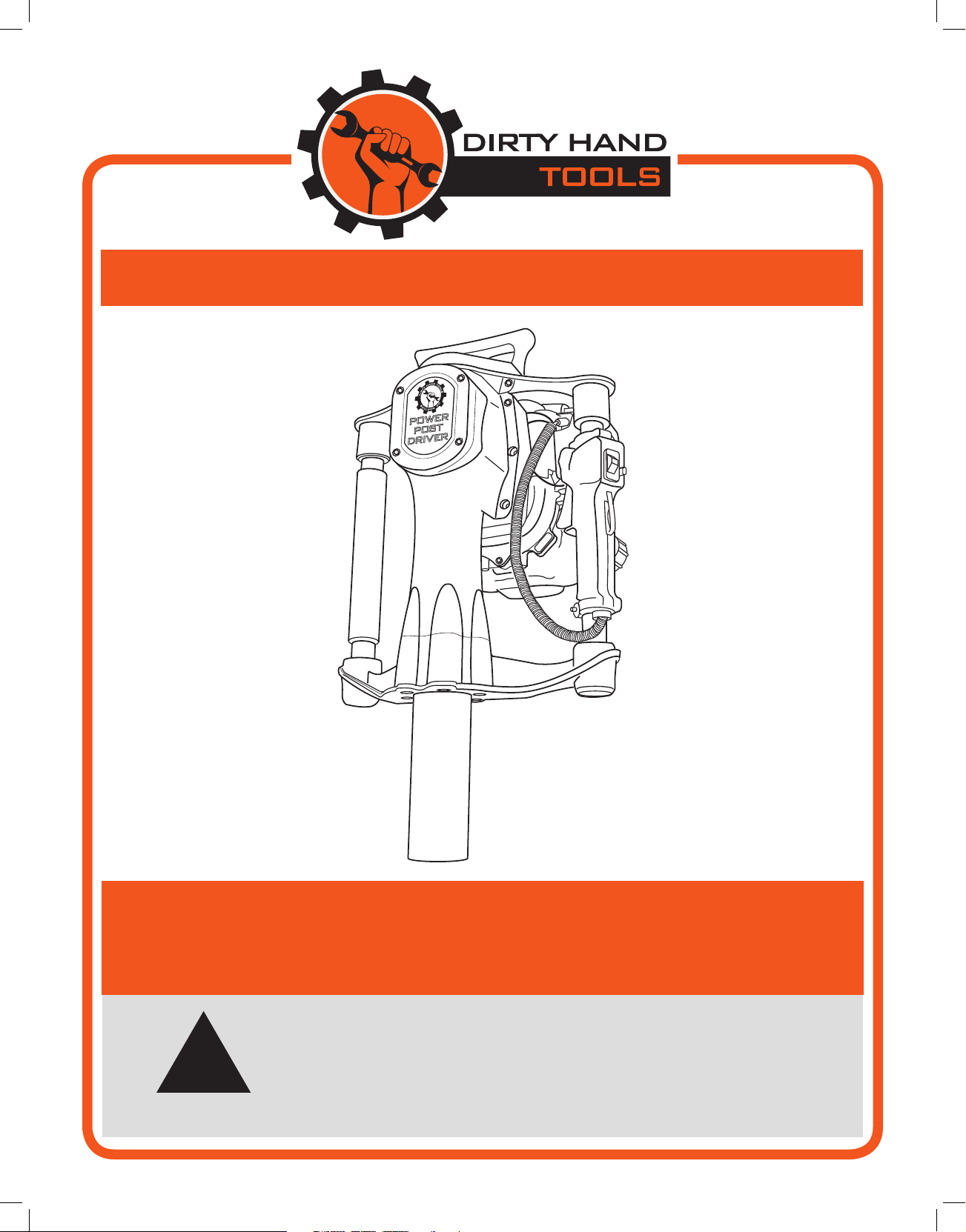
POWER POST DRIVER
O
I
!
MODELS # 103400 & 104369
Operation Manual
is safety alert symbol identies important safety messages in
this manual. Failure to follow this important safety information
may result in serious injury or death.
Part # 104615 Rev B
Page 2

For Service or Questions
Call 1-877-487-8275
720-287-5182
www.dirtyhandtools.com
Dirty Hand Tools® is a brand of
1100 W 120th Ave, Suite 600
Westminster, CO 80234 • 720-287-5182
Page 3

Table of Contents
Important Safety Information
Intended Use ..............................................................................4
Personal Protective Equipment ..................................................4
General Safety ............................................................................5
Safety Decals ..............................................................................6
Pre-Operation Check ...................................................................7
Power Post Driver Overview ........................................................8
Filling with Gasoline and Oil .....................................................10
Starting the Engine .....................................................................11
Operation ....................................................................................12
Maintenance
Maintenance Check List ...........................................................13
Checking/Changing Engine Oil ...............................................14
Replacing the Air Cleaner .........................................................15
Changing/Cleaning the Spark Plug ..........................................16
Spark Arrestor Cleaning/Replacement ......................................17
Crankshaft and Piston Lubrication ...........................................18
Troubleshooting ..........................................................................18
Parts List......................................................................................19
Warranty & Specications ......................................... Back Cover
3
Page 4

Important Safety Information
!
WARNING
WARNING: Read and thoroughly understand all instructions
and safety information before assembling or operating this Power
Post Driver. Failure to do so may cause serious injury or death.
Do not allow anyone to operate this equipment who has not read
this manual. As with all power equipment, a Power Post Driver
can be dangerous if assembled or used improperly. Do not operate
this equipment if you have doubts or questions concerning safe
operation.
Call our customer service department at 720-287-5182,
1-877-487-8275, or visit www.dirtyhandtools.com if you have any
questions or concerns about the safe operation of this equipment.
!
DANGER
Intended Use
Do Not Use the Power Post Driver for any purpose other than
for which it was designed. e Power Post Driver was designed to
drive fence posts, ground rods, form pins, and other similar items
into the ground. Any other use is unauthorized and may result in
serious injury or death.
Personal Protective Equipment
When operating this Power Post Driver it is essential that you wear
safety gear including goggles or safety glasses, adequate clothing
and tight fitting gloves. Always wear ear plugs or sound deafening
headphones to protect against hearing loss when operating this
Power Post Driver. Always wear sturdy footwear. Never wear
sandals, sneakers or open shoes, and never operate the Power Post
Driver with bare feet. Bystanders should wear safety glasses and
hearing protection while in the presence of this power tool during
operation.
!
CAUTION
Whenever you leave the operation position to raise or position a
fence post or make other adjustments always shut o the engine.
4
Page 5

Important Safety Information
General Safety
Failure to follow warnings, cautions, assembly and operation
instructions in the Operation Manual may result in serious injury
or death.
!
DANGER
READ THE OPERATION MANUAL BEFORE
OPERATION.
• Do not permit children to operate this equipment at any time.
Do not permit others that have not read and understood the
complete Operation Manual to operate this equipment.
• Keep all people and pets away from the work area when
operating the Power Post Driver.
• Do not operate the Power Post Driver when under the influence
of alcohol, drugs or medication.
• Do not allow a person who is tired or otherwise impaired or not
completely alert to operate the Power Post Driver.
!
DANGER
ALWAYS CHECK FOR THE PRESENCE OF
UNDERGROUND UTILITIES BEFORE USING
THE POWER POST DRIVER
• Always operate the Power Post Driver in the vertical position.
• Never use the Power Post Driver inside a contained area, exhaust
produced as Carbon Monoxide is a dangerous poison.
• Never, under any conditions, remove, bend, cut, fit, weld, or
otherwise alter standard parts on the Power Post Driver.
• Improper maintenance could lead to serious injury.
• Always use two hands and grip the Power Post Driver firmly
when operating.
5
Page 6
Important Safety Information
• Never run the engine in an enclosed area or without
proper ventilation as the exhaust from the engine
contains carbon monoxide, which is an odorless, tasteless,
and deadly poisonous gas.
• Fill the gasoline tank outdoors with the engine off and
allow the engine to cool completely.
• Do not operate the engine with the air cleaner or cover
over the carburetor air-intake removed, except for
adjustment. Removal of such parts could create a fire
hazard.
• e muer and engine become very hot with use and
can cause a severe burn; do not touch. Allow the engine
to cool before refueling, doing maintenance, or making
adjustments.
Safety Decals
Safety labels on the brush mower are to remind you
of important information while you are operating the
unit. Make sure all safety warning decals are attached
and in readable condition. Replace missing or defaced
decals. Contact Dirty Hand Tools at 1-877-487-8275 for
replacement decals.
READ OPERATOR’S MANUAL BEFORE USE
Allow engine to cool down before refueling
Gasoline is highly flammable, use caution
Do not operate indoors or enclosed areas
Exhaust contains Carbon Monoxide
Check for underground utilities before use
6
0 0 0 0 0 0
Page 7

Pre-Operation Check
1. Visually inspect your Power Post Driver before use. e interior
of the chuck tube should be checked for obstructions, damage
or wear to the chuck tube and anvil inside. e outer surfaces of
the driver should also be inspected for any defects.
2. Do not use the Power Post Driver if there is any damage or
wear until the damage or wear is corrected and repaired.
3. Check all fluid levels, i.e. engine oil and fuel and fill as needed
as per manufacturer’s specifications. Proper oil level is essential
to the proper operation of the Power Post Driver.
!
WARNING
THE POWER POST DRIVER IS SHIPPED WITHOUT
FLUIDS. OIL MUST BE ADDED TO THE ENGINE
BEFORE STARTING.
Overfilling of the oil will result in loss of power and may cause
permanent damage to the engine.
!
WARNING
USE ALL RECOMMENDED SAFETY EQUIPMENT.
4. Secure the driver on a solid surface, i.e. tailgate, bench, or clear,
solid ground and position your body in a safe position. DO
NOT start the driver anywhere but an open, well-ventilated
area. It is recommended that the Power Post Driver only be
used outdoors and never inside an enclosed building.
7
Page 8

Power Post Driver Overview
Carrying
H andle
Crankcase
Cov er
T humb
O n/ O ff
S witch
EP DM
F oam Grip
O
I
I dle L ock
S witch
T hrottle
T rigger
I dle L ock
R elease
F uel F ill
Cap
F uel
T ank
H ammer
Cov er
8
Page 9

Air
Cleaner
Power Post Driver Overview
R ecoil
S tarter
P riming
B ulb
Choke
S witch
F uel F ill
Cap
F uel
T ank
Mufer
O il F ill/
Dipstick
EP DM
F oam Grip
9
Page 10

Filling with Gasoline and Oil
!
WARNING
ADD OIL BEFORE STARTING THE ENGINE
e Power Post Driver is shipped without uids installed.
Keep the caps on the fuel and oil fills until you are ready to pour
either gasoline or oil into the correct fill.
1. Place the machine on a level surface, add some SAE 10-30W
engine oil into the oil fill and wait one minute for the oil to
settle, then continue filling with oil.
2. Check the dipstick and continue adding oil a little at a time,
rechecking the dipstick until the oil reaches the fill mark. Be
careful not to overfill.
3. Fill the fuel tank with fresh, unleaded gas (min. 85 Octane),
to 1/4” from the top of the ll neck to allow for expansion. Be
careful not to overll and reinstall the cap before starting.
!
WARNING
ALWAYS FILL THE TANK WITH
ENGINE OFF AND COOL.
ALWAYS CHECK THE OIL LEVEL
BEFORE OPERATING.
Allow the engine to cool for at least two minutes before removing
the fuel cap.
Before performing any adjustments to the Power Post Driver or
any maintenance, stop the engine, wait five minutes to allow parts
to cool.
10
Page 11

Choke
O pen
P osition
T hrottle
T rigger
P riming
B ulb
Figure 1
Engine O N /
O F F S witch
F uel R eturn
L ine
I dle L ock
S witch
Starting the Engine
Starting the Engine
1. To start a COLD engine, move the choke lever upwards to
the CLOSED position (see Figure 1). Lock the throttle by
depressing the trigger and while the trigger is depressed, push
in the button next to the thumb switch. Hold the button in and
release the trigger. e throttle is now in the high idle position
(see Figure 2).
2. To start a WARM engine, move the choke lever downwards to
the OPEN position and do not lock the throttle into the high
idle position.
3. Press the priming bulb repeatedly until fuel can be seen in the
clear-plastic fuel return tube (see Figure 1).
4. Slide the engine ON/OFF switch on throttle handle down or
into the ON position. Grasp the recoil starter handle and pull
lightly until you feel resistance, then pull quickly towards you
and return the recoil starter slowly. To prevent damage to the
starter, do not allow the recoil starter cord to snap back against
the engine.
5. If the choke lever was moved to the CLOSED position to
start the engine, gradually move it to the open position as the
engine warms up. As the engine warms up also release the high
idle lock slightly depressing the trigger and then immediately
releasing it. Use caution as to not engage the clutch.
!
WARNING
Figure 2
TO PREVENT PERSONAL INJURY OR DAMAGE TO
O
THE POST DRIVER TURN THE ENGINE TO THE OFF
POSITION BEFORE FOLLOWING THE
I
RESTARTING A HOT ENGINE PROCEDURE
Restarting a Hot Engine
If the engine is operated at high ambient temperature, then turned
off and allowed to sit for a short period, it may not restart on the
first pull of the recoil starter. Follow the following
1. Turn the engine switch to the OFF (see Figure 2).
2. Move the choke lever to the OPEN position (see Figure 1).
3. Hold the throttle trigger in the MAX speed position.
4. Pull the recoil starter handle 3 to 5 times.
5. Follow the Starting the Engine instructions above with the
choke lever in the OPEN position.
11
Page 12

Operation
Driving a T-Post
1. Have an assistant hold the t-post in the desired horizontal
position or manually drive the t-post into the ground a short
distance, so that it is free standing upright.
2. With the engine running, position the post driver over the top of
the t-post, gripping the handles firmly (see Figure 3).
3. e Power Post Driver should be positioned at the same angle as
the t-post that it will be driving (see Figure 4).
4. Apply steady downward pressure to the handles while depressing
the throttle trigger slightly to engage the clutch and hammer.
5. Once you are confident that the post is driving into the ground
straightly, depress the throttle trigger fully to operate at
maximum speed until the post is driven to the desired depth.
NOTE: Using a level will help ensure driving the post into the
ground at a perpendicular angle.
6. Release the throttle trigger dropping the engine RPM back to
idle before removing from the post.
7. When the engine has returned to idle, proceed to the next post
repeating the steps outlined above.
Figure 3
12
Figure 4
Page 13

Maintenance
!
WARNING
BEFORE PERFORMING ANY MAINTENANCE
PROCEDURE STOP THE ENGINE, WAIT FIVE 5
MINUTES TO ALLOW ALL PARTS TO COOL.
Regular maintenance is the way to ensure the best performance
and long life of your machine. Please refer to this manual and the
engine manufacturer’s owner’s manual for maintenance
procedures.
Maintenance Checklist
Maintenance Before After Every Every Every
Procedure Each Use 10 Hours 25 Hours
50 Hours 250 Hours
Check Engine Fuel Level X X X X
Check and Tighten all Fasteners X
Check Air Cleaner X
Clean/Replace Air Cleaner* X
Change Engine Oil** X X
Check Crankshaft & Piston lubrication X
Remove/Service Hammer and Anvil X
* Clean/change air filter more frequently if in dusty environment
** After the first 10 hours of operation change the engine oil, thereafter every 25 hours of operation
13
Page 14

Maintenance
Checking the Engine Oil
Check the engine oil level before each use, or every 10 hours
if operated continuously. Check the engine oil level with the
engine stopped and in a level position.
1. Remove the oil fill cap/dipstick and wipe it clean with a
paper towel (see Figure 5).
2. Insert and remove the oil filler cap/dipstick without screwing
it into the oil filler neck, then remove it to check the oil level
shown on the dipstick.
3. If the oil level is near or below the lower limit mark on
the dipstick, fill to the bottom edge of the oil fill hole with
SAE 10-30W engine oil. See the SAE Viscosity Chart for
other oil weights and temperatures (see Figure 6). To avoid
overfilling or underfilling, be sure the engine is in a level
position while adding oil.
4. Reinstall the oil filler cap/dipstick and tighten securely.
L ower
L imit
O il F ill
Cap
O il F ill
H ole
Changing the Engine Oil
1. Allow the engine to cool slightly. e engine oil will flow
more quickly when still warm. Be careful of draining hot oil.
2. Remove the oil fill cap, invert the power driver and carefully
drain the engine oil into an approved container for disposal.
3. Return the power driver to its upright position on a level
surface.
4. Some oil will remain in the engine after draining. When
refilling with fresh oil, start with about 2 ounces. Slowly add
SAE 10-30W engine oil into the oil fill and wait one minute
for the oil to settle, then continue filling with oil. Slowly add
enough oil to fill to the bottom edge of the oil fill hole (see
Figure 5).
5. Replace the dipstick. Be careful not to overfill.
Maximum
Oil Level
Minimum
Oil Level
Figure 5
SAE VISCOSITY GRADES
30W
10W - 30W
5W - 30W
- 2 0 0 2 0 4 0 6 0 8 0 1 0 0 ° F
AVERAGE OUTSIDE TEMPERATURE
14
Figure 6
Page 15

Maintenance
Replacing the Air Cleaner (Model 104369 - Honda Engine)
1. Press the latch tab on the top of the air cleaner cover and
remove the cover (see Figure 7).
2. Inspect the air cleaner filter. Clean or replace dirty air filter.
Always replace damaged air filter. Reinstall the air filter and
air cleaner cover.
Air
F ilter
Air F ilter
Cov er
Air F ilter
U pper
L atch T ab
U pper
L atch T ab
Air
Cleaner
Cov er
L ower
L atch T abs
Figure 7
Replacing the Air Cleaner (Model 103400 - DHT Engine)
1. Loosen the air filter cover latch (see Figure 8).
2. Set the air filter cover aside.
3. Remove the air filter.
4. Carefully clean the air filter with hot water and a mild detergent,
squeeze the water out and allow to dry. Soak the filter in fresh
oil, squeeze the excess oil out and replace in the filter housing.
5. Re-install the air filter cover.
Cov er
L atch
!
WARNING
To avoid personal injury or damage to the engine
do not run the engine without an air lter.
Figure 8
15
Page 16

Maintenance
Changing/Cleaning the Spark Plug
e recommended spark plug is the correct heat range for
normal engine operating temperatures. An incorrect spark plug
can cause engine damage.
H ex
B olt
Recommended Spark Plug: CM5H (NGK), CMR5H (NGK)
1. Remove the hex bolt on top of the engine cover (remove
two hex bolts on the top of the cover on the DHT engine
model) and slide the cover off (see Figure 9). Disconnect the
spark plug cap, and remove any dirt from around the spark
plug area. Remove the spark plug with a 5/8-inch spark plug
wrench (see Figure 10).
2. Inspect the spark plug. Replace it if damaged or badly
fouled, if the sealing washer is in poor condition, or if the
electrode is worn. Measure the spark plug electrode gap with
a wire-type gauge. For good performance, the spark plug
must be properly gapped and free of deposits. Correct the
gap, if necessary, by carefully bending the side electrode. Gap
should be: 0.60 0.70 mm (0.024 0.028 in)
3. Install the spark plug carefully, by hand, to avoid crossthreading. After the spark plug is seated, tighten with a
5/8-inch spark plug wrench to compress the sealing washer.
When installing a new spark plug, tighten 1/2 turn after the
spark plug seats to compress the washer.
4. When reinstalling the original spark plug, tighten 1/8 1/4 turn after the spark plug seats to compress the washer.
A loose spark plug can overheat and damage the engine.
Overtightening the spark plug can damage the threads in
the cylinder head.
5. Attach the spark plug cap to the spark plug. Reconnect the
spark plug cap.
6. Install the top cover, and tighten the 5mm hex bolt securely.
Engine
Cov er
S park
P lug Cap
Figure 9
S park
P lug
16
Figure 10
Page 17

Maintenance
Spark Arrestor Cleaning/Replacement
1. Remove the 5mm hex bolt on top of the engine cover and slide
the cover off (see Figure 9).
2. Remove the three 4mm x 6mm self-tapping screws from the
spark arrester and remove the spark arrester and the exhaust filter
from the muffler (see Figure 11).
3. Pinch the exhaust filter, strike lightly with a finger, and remove
carbon deposits. Be careful not to strike strongly. e exhaust
filter must be free of breaks and holes. If it is damaged or fouled
excessively, replace with a new exhaust filter.
4. Use a brush to remove carbon deposits from the spark arrester
screen. Be careful to avoid damaging the screen. e spark
arrester must be free of breaks and holes. Replace the spark
arrester if it is damaged.
5. Install the exhaust lter and spark arrester in the reverse order
of disassembly. When you install the spark arrester, the spark
arrester’s outlet must point to the side opposite the spark plug.
6. Replace the engine cover, reinstall the hex bolt and tighten
secu re ly.
S park
Arrester
O utlet
S elf- T apping
S crews
Mufer
Exhaust
F ilter
S park
Arrester
Figure 11
17
Page 18

Maintenance
O
I
Crankshaft and Piston Lubrication
1. Remove four hex bolts and crankshaft cover (see Figure 12).
2. Inspect the color and amount of grease inside the crankcase.
ere should be a ring of grease collected to the wall inside
the crankcase. Should the depth of the ring from the wall
inward measure 1/4” or less this indicates the grease is low.
3. If the amount of grease is low, add a small amount. e
maximum level should not be more than 1/2”.
NOTE: Overfilling with grease can damage the power driver.
4. If the grease is discolored, clean out old grease and add new
grease level with the bottom edge of the crank pin head.
5. Inspect the o-ring seal and replace it on the crankcase cover.
6. Replace the crankcase cover and tighten the hex bolts.
H ex B olts
4 P laces
Crankshaft
Cov er
Figure 12
Crankshaft grease
should be between
1 / 4 ” to 1 / 2 ” thick
on inside walls and
be clear, if dark or
discolored it should
be replaced.
Troubleshooting
PROBLEM SOLUTION
Engine will not start • Add gas to gas tank
• Connect spark plug wire to spark plug
• Move choke upwards to CLOSED position
Engine runs rough, oods during operation • Clean or replace air cleaner
Engine is hard to start • Drain old fuel and replace with fresh
• Make sure spark plug cap is securely attached to plug
Engine misses or lacks power • Clean or replace air cleaner
• Replace spark plug and adjust gap
• Drain, clean and rell gas tank
Engine stops suddenly • Low quality or deteriorated gasoline, drain and replace
• Spark plug cap is damaged or loose
• Move choke downwards to OPEN position after start
Power Post Driver runs slowly • Engine oil too full, check dipstick and remove some oil
Recoil is dicult to pull • Remove the spark plug and pull the recoil starter cord
several times until it pulls freely. Replace spark plug.
• Check oil dipstick and remove some oil if necessary.
18
Page 19

Parts List
Item # Part Name Part Qty
4 5 4 4
3 8
1
2
3
4
1 Hex Bolts, M8x15 2
2 Top Handle Bolts, M8x20 4
3 Upper Handle 1
4 Fixed Plate 1
5 Handle Cup 2
6 Hex Bolts, M5x15 4
3 7
3 5
4 3
4 0
4 6
3 5
3 9
5
7 Crankcase Cover 1
8 O-Ring Seal 75x1.8 1
1 1
1 0
78
6
9 Crank Pin 1
10 Crankshaft 1
11 Hex Bolts, M6x25 6
12 Post Driver Body 1
13 Cylinder 1
14 Bush Bearing 2
9
15 Connecting Rod 1
16 12 Retainer 1
4 1
4 2
3 8
4 7
3 6
3 7
1 2
1 3
17 Wrist Pin 12x32 1
18 Piston 1
19 O-Ring Seal 37.5x3.5 3
20 Hammer 1
1 4
21 Anvil O-Ring Retainer 1
22 O-Ring Seal 40x5.3 2
1 5
1 7
3 4
3 3
3 2
2 3
2 2
2 4
2 5
1 6
1 8
1 9
2 0
2 1
2 6
2 7
2 8
2 9
23 Big Retainer 1
24 Anvil O-Ring Cup 1
25 Anvil 1
26 O-Ring Seal 45x3.5 1
27 O-Ring Seal 56x1.8 1
28 Chuck Tube 1
29 Lower Driver Body 1
30 Hex Bolts, M8x60 6
31 Handle Anti-Vibration Spring 4
32 Handle Tube 1
33 Switch 1
34 Handle Tube 2
35 Bearing, 6004-2RS 2
36 Bearing, 6000-2RS 1
37 42 Retainer 2
38 20 Retainer 2
39 Key, 4x4X12 1
40 Gear 1
3 1
3 0
41 Bearing, 6201-2RS 1
42 Hex Bolts, M6x30 4
43 Clutch Housing 1
44 Clutch Drum 1
45 Cover 1
46 Pin 2
47 Gasket 1
19
Page 20

Warranty & Specications
IMPORTANT NOTICE
We, the manufacturer, reserve the right to change the product and/
or specifications in this manual without notification. e manual is for
information usage only and the pictures and drawings depicted herein are
for reference only.
Warranty Repair and Service
Do not return this product to the store for warranty issues or repair. Call
our customer service department at 720-287-5182, 1-877-487-8275, or
visit www.dirtyhandtools.com for the location of the nearest service center.
Record the information below for future reference.
Model No.
Serial No.
Date of Purchase
Place of Purchase
Specications
SKU/Part No. 103400 104369
Description Power Post Driver Power Post Driver
Engine 31cc DHT Engine* 35cc Honda Engine*
EPA Approved EPA Approved
Engine Type 4-stroke, single cylinder 4-stroke, single cylinder
Engine Fuel Capacity 20.29 fluid ounces (600mL) 21.76 fluid ounces (643mL)
Engine Oil Capacity** 2.37 fluid ounces (70mL) 3.4 fluid ounces (100mL)
Dimensions 23”L x 13”W x 14” D 23”L x 13”W x 14” D
Weight 34 Lbs. (Shipping Weight 45 Lbs.) 34 Lbs. (Shipping Weight 45 Lbs.)
Warranty 2 Year / 2 Year Limited Warranty 2 Year / 2 Year Limited Warranty
*As rated by engine manufacturer
** Not included, shipped without engine oil
Dirty Hand Tools® is a brand of
1100 W 120th Ave., Suite 600
Westminster, CO 80234 • 720-287-5182
For Service or Questions
Call 1-877-487-8275
720-287-5182
www.dirtyhandtools.com
 Loading...