


PROFESSIONAL NETWORK TESTING & PROTOCOL ANALYSIS
TM
PINGER PLUS
+
NETWORK IP TESTER
12-1121
Direktronik AB
K
onsul Johnsons väg 15
149 45 Nynäshamn
www.direktronik.se
USER’S GUIDE
, HANDBUCH, MANUEL D’UTILISATEUR
2
English
3
English
BOX CONTENTS
• Pinger Plus Network IP Tester • AC Adapter • Carrying case
• Four AA Alkaline Batteries •User Guide
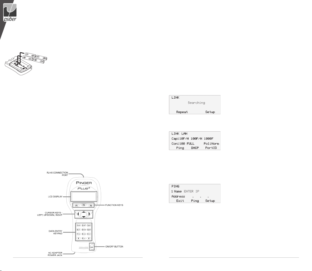
BATTERY
The Pinger Plus operates on four AA alkaline batteries. Remove the battery cover at the back of the unit and
insert the batteries with the orientation as shown. Battery
polarity is marked inside the battery well for reference.
TECHNICAL OVERVIEW
The Pinger Plus Network IP Tester uses the “PING” function to send a data
packet to another IP address on a network or respond to a PING sent to its
own IP address. The PING test is used to verify connectivity, measure round
trip communications time, check data integrity, determine a MAC address and
search a stored list or a range of IP addresses. The Pinger Plus provides a
DHCP Client mode and a Port Identification function with selectable blink rates
to locate which port on a hub or switch that a wall outlet is connected.
NETWORK COMPATIBILITY
The Pinger Plus is designed for testing an Ethernet network that uses the
IP protocol. The unit can communicate directly with a hub, switch, router, NIC
or other network device that uses 10baseT or 100baseT. The Pinger Plus will
identify when it is connected to a 1000baseT device but it cannot transmit/receive
a PING at 1000baseT.
MECHANICAL FEATURES
WEB BROWSER INTERFACE
The Pinger Plus can be configured by connecting it to the network and using
either Internet Explorer (6.0 or later) or Netscape (6.0 or later). To access the
Pinger Plus setup page, enter the Pinger IP address (shown in the Pinger IP
Address setup screen) in the browser URL window. All setup features can be
configured from the browser. The User Guide can also be displayed.
OPERATION
To test a hub, switch, router or NIC connect a patch cable from the RJ-45 port
on the equipment to the RJ-45 jack on the Pinger Plus.
LINK SCREEN
Turn on the Pinger Plus by pressing the “PWR” button. The unit scans the
RJ-45 connection searching for Link signals.
If no Link signals are found, a “No Link” message is displayed and a REPEAT function is
provided to rerun the search for a Link Partner.
When proper Link signals are found, the Pinger Plus displays the connection as
a LAN, NIC or an Auto MDI-X port; the capabilites of the Link Partner; the speed
and duplex the Pinger is using for the connection. When the Link is established,
the PING, DHCP and PortID function keys are
displayed. Disconnecting the Pinger will cause
the unit to immediately restart the search for
Link signals.
Note: If a Link Partner is transmitting NLP or MLT-3 Link signals instead of a Link
Code Word, the duplex mode is unknown (shown as “UN” in the LINK screen)
and the Pinger Plus will always connect at half duplex. PING tests can still be run
even if there is a duplex mode mismatch.
PING SCREEN
Pressing the PING function key in the Link
Screen presents the PING Screen. The Up/
Down cursor key is used to select:
1) enter and PING a new IP address
(1 to 99 times or continuously as shown next to “Name”)
2) PING one of eight preprogrammed IP addresses (see IP List Setup)
3) PING all of the one to eight preprogrammed IP LIST addresses
4) PING a Range of IP addresses or
5) PING one of eight Profiles(see Profile Setup).
4
English
5
English
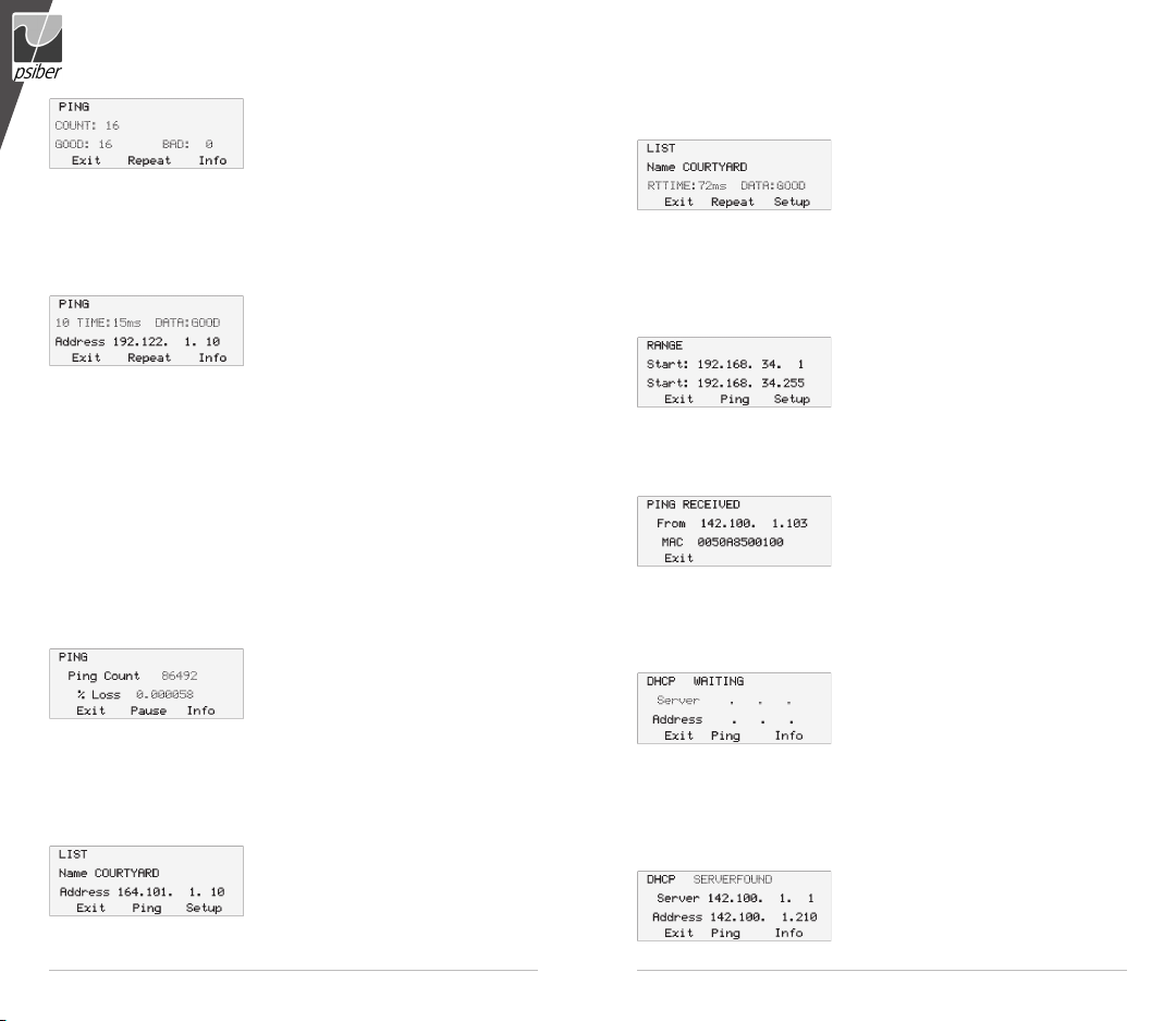
When an IP Address, IP List or IP Range is
selected, pressing the PING function key transmits the PING packet and “Wait” is displayed
until a response is received. A summary of the
PING responses is displayed showing the number of PINGs transmitted and the
number of Good and Bad responses. Pressing the Up/Down cursor key shows,
in numerical order, the results of each PING including the Round Trip Time and if
the received data is identical to the transmitted data (Data:Good) or the data has
been corrupted (Data:Bad).
Pressing the INFO function key displays the MAC address of the PINGed
IP address. If no PING response is received
within specified Timeout time (see Timeout
Setup), “No Response” is displayed. When the
PINGed IP address is in a different subnet than
the Pinger IP address, the unit first attempts to locate the default gateway. If the
gateway does not respond, the Pinger displays a “NOGW” message indicating
either the gateway is not operating properly or an incorrect gateway IP address
was entered. When a PING response is received from another subnet, the MAC
address of the Gateway is shown (GW MAC) by pressing the INFO function key.
Note: When the IP address of the device being PINGed is in the same subnet/
VLAN as the IP address of the Pinger, the Subnet Mask can be “ON” or “OFF” and
a Gateway IP address is not required. When the IP address is in a different subnet/
VLAN, the Subnet Mask must be “ON” with the mask entered and the IP address of
the Gateway must be entered. (See Subnet Mask Setup and Gateway Setup).
CONTINUOUS PING
When the Pinger is configured to PING continuously (See Ping Count Setup)
the letter “C” is displayed to the left of “Name” in the PING Screen. Pressing the
PING function key displays the number of
PINGs that have been sent and the percent
of the PINGs with No Response or that had
corrupted data. Pressing the Info function key
displays the PING Address and the running average of the Round Trip Times for
all PINGs that received a response. Pressing the Info function key again displays
the PING Address and the count of PINGs that had no response.
LIST SCREEN
When “IP List” is selected and the PING function key is pressed, each IP
address stored in the IP List (see IP List
Setup) is PINGed in turn. The same “Wait” and
“No Response” messages are displayed as
described above. After completing the PING of
the last stored IP address, the IP List Reponse screen is shown.
LIST RESPONSE SCREEN
The List Response screen shows the results of the PING to each of the stored
IP addresses. The Up/Down cursor key is used
to scroll through each IP address with Round
Trip Time, Data status and MAC address
presented for IP addresses that are found or
“No Response” for IP addresses that did not respond within the Timeout period.
Times less than one second are shown in milli-seconds (ms).
RANGE SCREEN
When “Range” is selected, the Range screen is displayed with start and stop
IP addresses. The first three octets of the start and stop address must be the
same and the fourth octet defines the range
from one to a maximum of 255 IP addresses.
Pressing the PING function key PINGs all the
addresses in the range simultaneously. Each
PING response can be viewed by pressing the Up/Down cursor key. Holding the
key will cause the responses to scroll faster.
PING RESPONDER MODE
The Pinger Plus will respond to a PING
request that is sent to the unit’s IP address.
When the unit is in the LINK Screen, a PING to
the Pinger Plus IP address presents the PING
Received screen. The Ping Received screen shows the IP and MAC addresses
of the PING source.
DHCP SCREEN
Pressing the DHCP function key in the Link Screen presents the DHCP Screen
and begins the DHCP client-server test.
Note: The MAC Address of the Pinger Plus
may have to be added to the Access List of the
DHCP Server for the Pinger messages to be
accepted - see your System Administrator for requirements.
The Pinger Plus transmits a “Discover” message to locate a DHCP server. If
no DHCP Server responds to the message within the DHCP Timeout period (see
Timeout Setup), the Pinger will retransmit the “Discover” message up to three
more times. If no DHCP Server responds after the fourth attempt, “No Response”
is displayed. Pressing the Repeat function key restarts the DHCP discover
process. When a DHCP Server responds
to the message, the Pinger displays “Server
Found” the IP Address of the Server and the IP
Address assigned to the Pinger.
6
English
7
English
Pressing the INFO key displays the Gateway IP Address and the Subnet Mask
used with the IP Address assigned by the DHCP Server. Note: If the DHCP Server
does not provide the Gateway IP Address, a 0.0.0.0 IP Address is displayed.
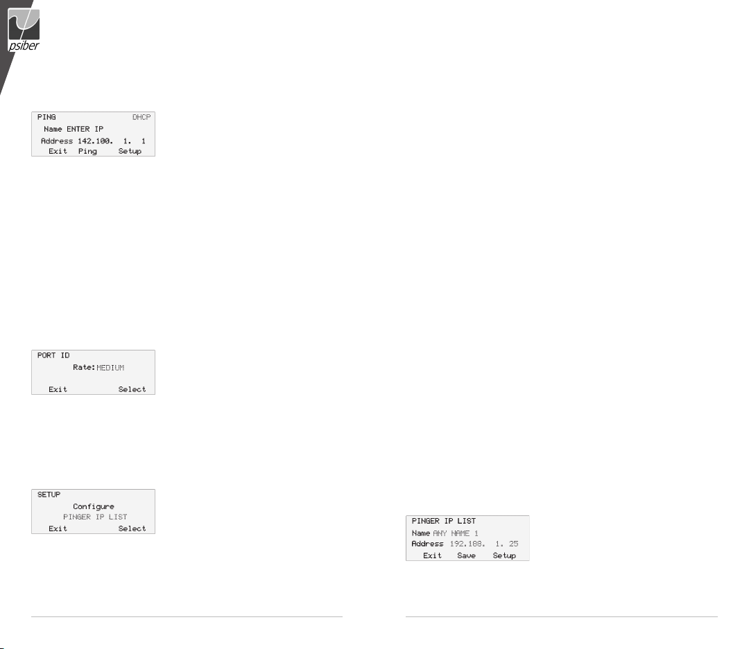
Pressing the PING key while in the DHCP Client mode presents the PING
Pressing the PING key from the IP Ping Screen transmits a PING that uses
the IP Address, Gateway Address and Subnet Mask provided by the DHCP
Server instead of the IP Address, Gateway Address and Subnet Mask that
were previously entered and stored in the Pinger. The Gateway IP Address is
automatically entered as the address to be PINGed (or the DHCP Server address
when Gateway information is not available). Alternatively, a new IP Address can
be entered or the Up/Down cursor key can be used to select a previously stored
address. Pressing the EXIT key returns the Pinger back to the LINK Screen and
clears the DHCP Server assigned addresses and mask. Pressing the Setup key
also clears the DHCP Server assigned information and transmits a DHCP release
packet to the DHCP server so that the IP address is available for reassignment.
PORT ID SCREEN
Pressing the PortID function key in the Link Screen presents the Port ID Screen.
As soon as this screen appears, the Pinger begins transmitting a pattern of Link sig-
tests. Hubs and switches from various manufacturers have different specifications
for the time it takes for Link signals to turn the Link LED on and off. The Pinger Plus
has four different blink rates and a continuous mode that can be selected by pressing the Up/Down cursor key. An initial test directly at the hub or switch will determine
the best blink rate setting before conducting a Port ID test at a wall outlet.
SETUP
1) Pinger IP Address Setup
2) Pinger Subnet Mask Setup
3) Pinger Gateway Setup
4) Pinger IP List Setup
5) Pinger MAC Screen
6) Profile Setup
screen with a “DHCP” message displayed and
the IP Address of the Gateway. If Gateway
information is not available, the DHCP Server
IP Address is shown.
nals that will cause the hub,switch or NIC Link
LED to blink or stay on continuously. Identifying
the specific port a wall outlet/PC is connected to
can aid in diagnosing the cause of failed PING
Pressing the SETUP key in any screen
presents the Setup Screen.The Up/Down
cursor key is used to display:
7) Default Profile
8) Ping Count
9) Packet Size
10) Time Out
11) Link Search
12) Power Down Time Setup
13) Password Setup or
14) Pinger Update .
Press the SELECT function key to enter the displayed setup screen.
The Pinger MAC is shown for information only and can not be changed.
IP LIST SETUP SCREEN
The IP List Setup screen is used to enter from one to eight names and IP
addresses. The Pinger can then PING the entries individually or PING all entries
sequentially.
DATA ENTRY – Use the Up/Down cursor key to select one of the eight
storage locations and press the right arrow key to display the cursor and begin
entering a new name or editing an existing one. Use the data entry keypad to
input the number or letter (each time the key is pressed the next letter or number
on the key is displayed). Pressing the right cursor key advances to the next
character. Pressing the left cursor key selects the previous character. Names can
be a maximum of ten characters long. Pressing the right cursor key an eleventh
time advances the cursor to the IP Address which is divided into four fields of
three characters. Only numbers can be input in the fields and the maximum
valid number for any field is 255. Single digits can be entered in any of the three
character locations and will be right hand justified when the cursor is moved to the
next field. Two digit numbers can be entered in the left two or right two character
locations. If an invalid number is entered, the cursor will not advance to the next
field. After entering or editing the name and IP address, press the SAVE function
key to store the information in non-volatile memory. The information is retained
even if the unit is turned off or the batteries are removed. To remove an entry
from the list, press the right cursor key to select the entry and then press the star
key. A “Delete Entry” message is displayed and pressing the SAVE function key
clears the selected name and IP Address.
PINGER IP SETUP SCREEN
The IP address for the Pinger Plus is input
from this screen. The unit comes programmed
with a default address of 192.168.1.42.

8
English
9
English
SUBNET MASK SETUP SCREEN
To Ping an IP address in a subnet different than the subnet of the Pinger Plus,
requires that the Subnet Mask be entered and “ON” and the appropriate Gateway
IP address has been entered. Mask “ON” and OFF” is selected with the Up/Down
Cursor key. A zero in the first field is an invalid mask entry and the Pinger defaults
to 255 when the mask is saved. NOTE: Subnet Mask and Default Gateway IP
address may be found by going to a computer on the subnet where the Pinger
Plus will be used, open the Windows Control Panel, open the network icon, open
the LAN icon, select TCP/IP Protocol and then select properties.
GATEWAY SETUP SCREEN
The IP address for the default Gateway (typically a router or a server) is input
from this screen.
PINGER MAC SCREEN
The Pinger Plus MAC address is displayed in this screen. The MAC for each
Pinger is unique and can not be changed. See Note in DHCP.
PROFILE SETUP SCREEN
A profile consists of a Profile name, Pinger Plus IP address, Subnet Mask on
or off, Subnet Mask, Gateway Address and a list of one to eight destination IP
addresses. One of the eight Profiles is selected using the Up/Down cursor, the
Profile name and Pinger Plus IP address is entered and the Next function key is
pressed. The Subnet Mask is entered and turned on or off and the Next fuction key
is pressed. The Gateway address is entered and the Next function key is pressed.
From one to eight destination IP addresses are entered and then the Save function
key is pressed.
DEFAULT PROFILE SCREEN
A default profile can be designated to be used initially when the Pinger Plus is
powered on.
POWER DOWN SETUP SCREEN
The Pinger Plus will automatically turn off after the time selected in the Power
Down Setup screen. Settings available are five minutes, fifteen minutes, thirty
minutes and on (must be turned off manually). Press the SAVE function key to store
the selected setting.
PASSWORD SCREEN
A password is required to configure the Pinger Plus from a web browser or
update the firmware. The password protects against a third party making unauthorized changes to the unit when it is connected to a network. The default password is
12345678. It is recommended that the default password be changed prior to initial
operation.
PING COUNT SETUP SCREEN
The Pinger Plus can be set to PING an IP address from 1 to 99 times or continuously. Pressing the Up/Down cursor key scrolls the number of times to PING from 1
to 99. The Continuous PING setting is shown by scrolling down from “1” or up from
“99”. Multiple PINGs are not available for Lists, Profiles or Ranges.
PING PACKET SIZE AND TIMEOUT SETUP SCREENS
The PING packet size has six settings from 50 to 1400 bytes. The time
the Pinger Plus waits for a PING or DHCP response before displaying a No
Response notice can be set from 1 to 40 seconds in one second increments.
LINK SEARCH SCREEN
The Link Search setup screen is used to set the length of time that the Pinger
Plus will monitor a wire pair for Link signals. Normal (about 2.5 seconds) is the
default setting or use the Up/Down cursor key to select the Long setting (about 5
seconds). Some switches, especially if configured for VoIP, require a longer time
to complete Link negotiations and the Long setting will provide more consistent
Link detection.
UPDATE PINGER SCREEN
The Pinger Plus firmware can be updated over the network as new revisions
are released. Notice of a new revision will be provided on the Psiber web site
(www.psiber.com). Download the new firmware file, connect the Pinger Plus to the
network, go to the Update Pinger Setup screen, press the Select function key and
the unit will Link to the network and enable the firmware update mode. Next run the
downloaded file on the computer. The program will ask for the current IP address
of the Pinger Plus (see Pinger IP Address Setup screen) and your password.
When the update is complete the program will notify the user and the Pinger Plus
immediately goes to the Link screen and searches for the Link.
WARNING: Any disruption while programming is in process will result in the unit
being unuseable and will have to be returned to the factory for repair. Install a fresh
set of batteries or connect the AC adapter to the unit before starting an update.
POWER
Duration – The Pinger Plus will typically provide about 5 to 6 hours of operation
from a set of four AA alkaline batteries. An AC adapter is also provided which will
power the unit but does not recharge the batteries.
Auto Power Down – The Pinger will automatically turn off after the time selected
in the Power Down Setup screen or will run continuously until manually turned off
when “ON” is selected for Power Down.
Low Battery – When the batteries are below the level required for the Pinger
Plus to operate properly, a battery graphic appears in the upper right hand corner
of the display.

10
English
11
Deutsch
WARRANTY
Psiber Data warrants that the product shall be free from defects in parts or workmanship for a period of 12 months from the
date of purchase if used in accordance with Psiber Data operating specifications.
THIS IS THE ONLY WARRANTY MADE BY Psiber Data AND IS EXPRESSLY MADE IN LIEU OF ALL OTHER WARRANTIES EXPRESSED OR IMPLIED, INCLUDING BUT NOT LIMITED TO ANY IMPLIED WARRANTIES OF MERCHANTABILITY OR FITNESS FOR ANY PARTICULAR PURPOSE.
Should any parts or workmanship prove defective, Psiber Data will repair or replace at Psiber Data’ option, at no cost to the
Buyer except for shipping costs from the Buyer’s location to Psiber Data. This is Buyer’s SOLE AND EXCLUSIVE REMEDY
under this Agreement. This warranty does not apply to products which have been subject to neglect, accident or
improper use, or to units which have been altered or repaired by other than an authorized repair facility.
For US-Customers:
Return of Equipment – To return a product to Psiber Data Systems Inc., first obtain a Return Authorization number from our
Customer Service by calling +1 619-287-9970. The RA# must be clearly marked on the shipping label, or the package will
not be accepted by Psiber Data Systems Inc. See sample label below.
To: Psiber Data Sytems Inc.
7075-K Mission Gorge Road
San Diego, CA 92120
RA# XXXXXXXX
For European-Customers:
Return of Equipment – To return a product to Psiber Data GmbH, first obtain a Return Authorization number from our
Customer Service by calling +49-89-89136060. The RA# must be clearly marked on the shipping label.
To: Psiber Data GmbH
Felix-Wankel-Str. 4
82152 Krailling
Germany
RA# XXXXXXXX
Copyright 2009 Psiber Data. All rights reserved. Pinger, Plus+, psiber and the Psiber logo are trademarks of Psiber Data.
P/N 1005-0650-0000 Rev. E
LIEFERUMFANG
• Pinger Plus Network IP Tester • 4x AA Alkali Batterien
• Universal Netzteil • Handbuch
• Nylon-Tasche
BATTERIEN
Der Pinger Plus arbeitet mit 4 AA Alkali
Batterien. Entfernen Sie den Batteriefachdeckel
auf der Rückseite und legen Sie die Batterien
unter Beachtung der korrekten Polarität in das
Gerät ein. Die richtige Polarität ist im Batteriefach
eingedruckt.
TECHNISCHE ÜBERSICHT
Der Pinger Plus IP Tester nutzt grundsätzlich die „PING“ Funktion, bei der ein
Datenpaket an eine andere IP Adresse im Netzwerk geschickt wird, auf die das
Gerät mit seiner IP Adresse antwortet. Außerdem antwortet der Pinger Plus auch
auf PING Anfragen, die an seine eigene IP Adresse gesendet werden. Der PINGTest wird hierbei dazu genutzt um:
- Grundsätzlich zu testen, ob eine Datenverbindung besteht
- Antwortzeiten (round trip time) zu messen
- Datenintegrität zu überprüfen
- MAC Adressen herauszufinden
- Gespeicherte Listen oder einen Bereich von IP Adressen im Netzwerk zu suchen
Der Pinger Plus bietet einen DHCP Client Modus, um die DHCP Server Funktionalität zu testen. Zusätzlich verfügt er über eine Port Identifikationsfunktion mit
einstellbarer Blinkrate, um herauszufinden, welcher Port eines HUBs oder Switches
mit der entsprechenden Wanddose verbunden ist.
NETZWERK KOMPATIBILITÄT
Der Pinger Plus ist dafür entwickelt, die IP Protokolle eines Ethernet Netzwerk
zu testen. Das Gerät kann direkt mit einem HUB, Switch, Router, NIC oder anderem Netzwerkgerät, das 10BaseToder 100BaseT verwendet, kommunizieren.
Der Pinger Plus zeigt auch an, wenn er mit einem 1000BaseT Gerät verbunden
ist. Es ist allerdings nicht möglich, einen Ping mit 1000BaseT Geschwindigkeit zu
senden oder zu empfangen. Typischerweise wird dann der Ping auf 100BaseT
durchgeführt.

12
13
Deutsch
Deutsch
MECHANISCHE FUNKTIONEN
WEB BROWSER INTERFACE
Der Pinger Plus kann konfiguriert werden, indem Sie es an das Netzwerk
anschließen und mit einem Browser entweder Internet Explorer (6.0 oder höher)
oder Netscape (6.0 oder höher) ansprechen. Um den Pinger Plus zu konfigurieren,
geben Sie die IP Adresse (siehe IP Address Setup Menü) in dem URL Feld des
Browsers ein. Alle Setup Funktionen können über den Browser eingestellt werden.
Auch kann das Handbuch (in Englisch) angezeigt werden.
BEDIENUNG
Um einen HUB, Switch, Router oder NIC zu testen, verbinden Sie den RJ-45
Anschluss mit dem Pinger Plus.
LINK MENÜ
Schalten Sie den Pinger Plus mit der „PWR“-Taste ein. Das Gerät wird automatisch
über den RJ-45 Anschluss nach einem Link Signal suchen. Wird kein Link-Signal
gefunden, wird „No Link“ angezeigt. Durch Drücken der Funktionstaste „REPEAT“ wird erneut
versucht eine Verbindung herzustellen. Wenn
ein Link-Signal gefunden wurde, zeigt der Pinger
Plus die Art des angeschlossenen Gerätes an als: LAN, NIC oder als Auto MDI-X Port.
Außerdem wird die Funktionalität des Ports angezeigt (10,100 oder/und 1000Mbit, Full
oder Half Duplex), zusätzlich Geschwindigkeit
und Duplexmodus, mit dem der Pinger Plus mit
dem Gegengerät kommuniziert. Auch wird die
Polarität (normal oder gekreuzt) ermittelt. Wenn
eine Verbindung zum Port aufgebaut wurde, erscheinen die Funktionstasten „PING“,
„DHCP“ und „PORT ID“. Eine Trennung der Verbindung bewirkt, dass der Pinger Plus
sofort wieder nach einem Link Signal sucht.
Anmerkung: Wenn das Gegengerät ein NLP oder MLT-3 Linksignal sendet,
statt eines „Link Code Word“, wird der Duplexmodus mit „UN“ (unbekannt) angezeigt und die Verbindung wird immer in Half Duplex aufgebaut. Selbst wenn der
Duplexmodus bei dem Gegengerät und Pinger Plus unterschiedlich ist, kann immer
noch ein Ping-Test durchgeführt werden.
PING MENÜ
Mit der Funktionstaste „PING“ (diese ist je
nach geladenem Menü F1-Taste oder F2-Taste)
gelangen Sie in das Ping Menü. Mit den „Auf/
Ab“-Pfeiltasten können Sie wählen zwischen:
1) Ping Eingabe und anpingen einer neuen IP Adresse
2) List Anpingen einer von 8 vorprogrammierten IP Adressen
(siehe auch IP List Setup)
3) List Name IP List -Anpingen aller vorprogrammierten IP Adressen aus der IP LIST
4) Range Anpingen eines Bereichs von IP Adressen
5) Profile Anpingen eines von den acht Profilen (siehe auch Profil Setup).
Wenn eine IP Adresse, IP Liste oder ein IP Bereich ausgewählt wurde, wird
durch Drücken der Funktionstaste „PING“ das Ping Paket gesendet und „Wait“
angezeigt, bis eine Antwort empfangen
wird. Dann wird die Zusammenfassung der
Ping-Antworten angezeigt, d.h. die Anzahl der
gesendeten „PING-Pakete“ und die Anzahl der
guten oder schlechten Antworten. Durch Betätigen der „Auf/Ab“-Pfeiltasten werden
die einzelnen Ergebnisse in numerischer Reihenfolge angezeigt, einschließlich der
Antwortzeit (Round Trip Time) und ob das empfangene Datenpaket identisch mit
den gesendeten war (Data:Good).
Mit der Funktionstaste „INFO“ können Sie die MAC Adresse, der angepingten
IP Adresse, anzeigen lassen. Wurde innerhalb der zulässigen Zeit keine Antwort
empfangen (siehe auch Timeout Setup), wird
„No Response“ angezeigt. Befindet sich die
angepingte IP Adresse in einem anderen
Subnet als die des Pinger Plus, wird das Gerät
versuchen das „default Gateway“ anzusprechen. Gibt dieses Gateway keine
Antwort, wird “NOGW“ (bedeutet „No Gateway“) angezeigt. Dies bedeutet, dass
entweder das Gateway nicht einwandfrei arbeitet oder die Gateway IP Adresse im
Pinger Plus nicht korrekt eingegeben wurde. Wurde eine Antwort einer IP Adresse
aus einem anderen Subnet empfangen, kann die MAC Adresse des Gateway (GW
MAC), durch Drücken der Info Taste, angezeigt werden.

14
15
Deutsch
Deutsch
Anmerkung: Wenn die IP Adresse eines Gerätes, welches sich in demselben
Subnet/VLAN wie der Pinger Plus befindet, angepingt wird, ist es irrelevant ob die
Subnet Maske an oder ausgeschaltet ist und auch eine Gateway IP Adresse wird
nicht benötigt. Befindet sich das Gerät in einem anderen Subnet/VLAN, muss die
Subnet Mask auf „ON“ gestellt sein, die richtige Maske und die Gateway IP Adresse
eingegeben sein (siehe auch Subnet Mask Setup und Gateway Setup).
CONTINUOUS PING (kontinuierlicher Ping)
Wird beim Pinger Plus die Einstellung Continuous (kontinuierlich) gewählt (siehe
auch Ping Count Setup), erscheint im Ping Menü
ein „C“ links neben „Name“. Drücken Sie die
Funktionstaste „PING“, um die Anzahl der ge-
sendeten Pings und den prozentualen Anteil der
Pings anzuzeigen, die keine Antwort erhielten bzw. fehlerhafte Datenpakete enthielten.
Durch Drücken der Funktionstaste „INFO“ erscheint die angepingte Adresse und der
laufende Durchschnitt der Antwortzeiten (Round Trip Times) für alle beantworteten
Pings. Bei nochmaligem Drücken der Funktionstaste „INFO“ wird die angepingte
Adresse und die Anzahl der Pings eingeblendet, die keine Antwort erhielten.
LIST MENÜ
Wenn „IP LIST“ ausgewählt und die Funktionstaste „PING“ gedrückt wird, wer-
den alle, in der IP List (siehe auch IP List Setup)
gespeicherten IP Adressen nacheinander
angepingt. Dieselben „Wait“ oder „No Respon-
se“ Meldungen, wie schon oben beschrieben,
werden angezeigt. Nach dem Anpingen der letzten gespeicherten IP Adresse wird
das IP „List Response“ Menü angezeigt.
LIST RESPONSE MENÜ (Testergebnisse gespeicherter IP-Adressen)
Das „List Response“ Menü zeigt die Testergebnisse für jede gespeicherte IP
Adresse an. Mit den „Auf/Ab“- Pfeiltasten kann
zwischen den Ergebnissen geblättert werden.
Für jede IP Adresse die auf den Ping geant-
wortet hat, werden: die Antwort Zeit (Round
Trip Time), Datenstatus (Data Good oder Bad, siehe oben) und MAC Adresse
angezeigt. IP Adressen, die nicht innerhalb der im Timeout Menü vorgegebenen
Zeit geantwortet haben, werden mit „No Response“ angezeigt. Zeiten unterhalb
einer Sekunde werden in Millisekunden (ms) angegeben.
RANGE MENÜ (IP Bereich)
Wenn „Range“ (also das Ansprechen eines Bereichs fortlaufender IP Adressen)
ausgewählt wurde, wird die Start und Stop IP
Adresse angezeigt. Die ersten drei Felder der
Start und Stop IP Adresse müssen identisch
sein. Somit kann maximal ein Bereich von
255 IP Adressen angepingt werden. Durch Drücken der Funktionstaste „PING“
werden alle IP Adressen des Bereichs gleichzeitig angepingt. Jede Antwort kann mit
den „Auf/Ab“-Pfeiltasten angesehen werden. Durch Halten der Pfeiltaste wird die
Bilddurchlauf—Geschwindigkeit („scrollen“) erhöht.
PING RESPONSE MODUS (Antwort Modus)
Der Pinger Plus antwortet auch auf einen
Ping, der an die Pinger IP Adresse gesendet
wird (z.B. von einem anderen Pinger oder PC).
Befindet sich das Gerät im Link Menü, dann
wird ein Ping Menü aufgerufen, in dem die IP Adresse des Absenders und dessen
MAC Adresse angezeigt wird.
DHCP MENÜ
Mit der Funktionstaste „DHCP“ gelangen
Sie in das DHCP Menü und starten den DHCP
Client-Server Test. Anmerkung: Die MAC Adresse des Pinger Plus muss ggf. zur Access List
des DHCP Servers hinzugefügt werden, um vom DHCP Server akzeptiert zu werden – Sprechen Sie ggf. mit Ihrem System Administrator für weitere Informationen.
Der Pinger Plus sendet eine „Discover“ Anfrage, um den DHCP Server zu loka-
lisieren. Wenn kein DHCP Server innerhalb der
im Timeout Menü gewählten Zeit (siehe auch
Timeout Setup) antwortet, wird der Pinger Plus
die „Discover“ Anfrage bis zu 3 Mal wiederholen.
Antwortet nach dem 4. Versuch kein DHCP Server, wird „No Response“ (keine
Antwort) angezeigt. Wenn ein DHCP Server auf die Anfrage antwortet, wird „Server
Found“, die IP Adresse des DHCP Servers und die dem Pinger zugeteilte IP Adresse angezeigt. Durch Drücken der Funktionstaste INFO erfahren Sie die Gateway IP
Adresse und die Subnet Mask, die zu der zugeteilten IP Adresse gehört.
Anmerkung: Wenn der DHCP Server keine Gateway Adresse zugewiesen hat,
wird 0.0.0.0 als Gateway IP Adresse angezeigt.
Durch Drücken der Funktionstaste „PING“ im DHCP Client Modus, gelangen Sie
in das Ping Menü, hier erscheint „DHCP“ in der rechten oberen Ecke der Anzeige
sowie die Gateway Adresse. Ist keine Gateway Adresse verfügbar, wird die DHCP

16
17
Deutsch
Deutsch
Server IP Adresse angezeigt. Wenn Sie aus diesem Menü ein Ping durchführen,
verwendet der Pinger Plus, die vom DHCP Server zugeteilte Pinger IP Adresse,
Gateway Adresse und Subnet Mask anstelle der im Setup manuell eingegebenen
Adressen. Es wird in diesem Menü die Gateway
IP Adresse automatisch zum Pingen vorgeschlagen (oder die DHCP Server IP Adresse,
wenn keine Gateway IP Adresse vorliegt).
Alternativ kann diese durch Überschreiben manuell geändert werden oder durch
die Auf/Ab Pfeiltasten eine vorher gespeicherte IP Adresse aufgerufen werden.
Durch Drücken der Funktionstaste EXIT kehren Sie in das Link Menü zurück und
löschen die vom DHCP Server zugewiesene IP Adresse, Gateway Adresse und
Subnet Mask. Auch die Funktionstaste Setup löscht die zugewiesenen Adressen
und sendet eine Freigabe Mitteilung an den DHCP Server, sodass diese Adressen
anderweitig zugewiesen werden können.
PORT ID MENÜ
Durch Drücken der Funktionstaste Port ID im Link Menü, gelangen Sie in das
Port ID Menü. Sobald dieses Menü erscheint sendet der Pinger ein Link Signal, das
die Link LED des Hubs, Switches oder der NIC blinken oder permanent leuchten
lässt. Dies ist sehr nützlich um herauszufinden, welche Wanddose bzw. PC an
welchen Port angeschlossen ist. Dadurch kann
oft schon die Ursache eines fehlgeschlagenen
Ping-Tests herausgefunden werden. Hubs und
Switche von verschieden Herstellern haben
unterschiedlichen Spezifikationen für die Zeit zwischen dem Empfang des Linksignals und dem Ein- und Ausschalten der LED. Der Pinger Plus hat 4 verschiedene
Blinkraten und den permanenten Modus, der durch drücken der „Auf/Ab“-Taste
gewählt wird. Es empfiehlt sich diesen Test erst einmal direkt am Port des Hubs
oder Switches auszuführen, um auffälligste Blinkgeschwindigkeit zu wählen.
SETUP (Einstellung)
Durch drücken der „Setup“-Taste in jedem
beliebigem Menü gelangen Sie sofort in das
Setup Menü. Mit der „Auf/ Ab“-Taste können Sie
folgende Untermenüs auswählen:
1) Pinger IP Address Setup – Die Pinger Plus Absender IP Adresse kann hier
eingestellt werden. Diese wird nur dann benutzt wenn als default Profile
„Pinger“ gewählt wurde.
2) Pinger Subnet Mask Setup – Einstellung der Subnet Mask
3) Pinger Gateway Setup – Einstellung der Gateway Adresse
4) Pinger IP List Setup – Hier kann eine Liste von häufig verwendeten
IP Adressen angelegt werden.
5) Pinger MAC Address Screen – Pinger MAC Adresse
6) Profile Setup – Hier definieren Sie bis zu 8 Profile mit Pinger Plus IP Adresse,
Gateway IP und Subnet Mask & zu pingende IP Adresse.
7) Default Profile –Definiert das Standard- Profil. Wird „Pinger“ ausgewählt,
verwendet das Gerät die Absender Adresse von Punkt 1-3. Ansonsten die im
Profil vorgegebenen.
8) Ping Count – Einstellung der Anzahl von Pings die jeweils durchgeführt werden
(zwischen 1-99)
9) Packet Size –Größe des Ping Paketes
10) Time Out – Zeit bis zum Empfang des Antwortpakets
Ping:1 bis max. 40 sec
DHCP: 1 bis max. 40 sec
11) Link search – Einstellung der Suchdauer: normal oder long
12) Power Down Time Setup – Ausschaltzeit bei Nichtaktivität – Sie können wählen
zwischen 5 min/15min/30min Ausschaltzeit bei Nichtaktivität oder Sie wählen
die Funktion Time: ON, dann schaltet sich das Gerät nicht automatisch bei
Nichtaktivität aus. Sie müssen es manuell ausschalten.
13) Password Setup – Passworteingabe (wichtig zur Browser Konfiguration)
14) Update Pinger – Firmware Update per Netzwerk
Durch drücken der Funktionstaste „Select“ gelangen Sie in das jeweilige Menü. In
dem Pinger MAC Menü (Pos 5) wird die Information nur angezeigt, kann aber nicht
geändert werden.
IP LIST SETUP MENÜ
In dem IP List Menü können zwischen 1-8
Namen und IP Adressen eingegeben werden.
Der Pinger kann dann jeweils die Einträge
einzeln oder in einer Sequenz anpingen.
DATENEINGABE – Benutzen Sie die „Auf/Ab“-Pfeiltasten, um einen der acht
Speicherplätze auszuwählen, dann drücken Sie die rechte Pfeiltaste und es
erscheint der Cursor in der Anzeige. Nun können Sie einen neuen Namen eingeben
oder den existierenden ändern. Benutzen Sie zur Eingabe der Zahlen und Buchstaben die Tastatur des Gerätes. Drücken Sie die rechte Pfeiltaste, um das nächste
Zeichen einzugeben. Durch Drücken der linken Pfeiltaste springt der Cursor zur
vorhergehenden Stelle. Ein Name kann maximal 10 Zeichen lang sein. Nach der
11. Stelle springt der Cursor zur IP Adresse, welche in 4 Felder mit je 3 Stellen
eingeteilt ist. Es können nur Zahlen bis maximal 255 eingegeben werden. Bei ein
oder zweistelligen Zahlen muss die Eingabe mit der rechten Pfeiltaste quittiert
werden, wodurch der Cursor in das nächste Feld springt. Wird eine nicht zulässige
Zahl eingegeben, bleibt der Cursor im entsprechenden Feld. Nach der Eingabe des
Namens und der IP Adresse speichern Sie das Ergebnis durch Drücken der

18
19
Deutsch
Deutsch
Funktionstaste „SAVE“. Diese Information befindet sich dann im nicht flüchtigen
Speicher und bleibt auch nach Ausschalten des Gerätes oder bei Batteriewechsel
erhalten. Um einen Eintrag zu löschen, drücken Sie die rechte Pfeiltaste zum Auswählen und dann die Sterntaste. Eine „Delete Entry“ Meldung wird angezeigt und
durch Drücken der Funktionstaste „SAVE“ wird der ausgewählte Eintrag gelöscht.
PINGER IP SETUP MENÜ
Die IP Adresse des Pinger Plus wird in diesem Menü eingegeben. Das Neugerät
ist mit einer Standard IP Adresse 192.168.1.42 vorprogrammiert.
SUBNET MASK SETUP MENÜ
Um eine IP Adresse in einem anderen Subnet, als dem Subnet in der sich der
Pinger Plus befindet, anzupingen, ist es notwendig die Subnet Mask einzugeben,
mit „ON“ einzuschalten und die entsprechende Gateway Adresse einzugeben. Um
Mask mit „ON“ und „OFF“ einzuschalten, betätigen Sie einfach die „Auf/Ab“-Pfeiltasten. Eine Null im ersten Feld ist eine nicht zulässige Eingabe und wird vom Pinger
zum Standard 255 abgeändert, sobald die Mask gespeichert wird.
Anmerkung: Die Subnet Mask und Gateway Adresse können üblicherweise an
einem Computer gefunden werden, der sich in dem Segment befindet, in dem der
Pinger Plus benutzt wird. Diese Informationen finden Sie in den Netzwerkeinstellungen, bei den Eigenschaften des TCP/IP Protokolls.
GATEWAY SETUP MENÜ
Die IP Adresse des Standard Gateways (typischerweise ein Router oder Server)
wird in diesem Menü eingegeben.
PINGER MAC MENÜ
Die MAC Adresse des Pinger Plus wird in diesem Menü angezeigt. Diese MAC
Adresse ist bei jedem Pinger eine andere und kann nicht geändert werden. Siehe
auch DHCP.
PROFIL SETUP MENÜ
Ein Profil besteht aus Profil Namen, Pinger Plus IP Adresse, Subnet Mask an
oder aus, Subnet Mask, Gateway Adresse und einer Liste von einer bis acht Ziel IP
Adressen. Es können bis zu acht Profile eingestellt werden. Sie wählen einfach das
entsprechende Profil mit den „Auf/Ab“- Pfeiltasten aus. Dann geben Sie den Profil
Namen und die Pinger Plus IP Adresse ein und bestätigen mit der Funktionstaste
„NEXT“. Nun die Subnet Mask eingeben und mit „ON“ oder „OFF“ an oder
abschalten und wieder mit der Funktionstaste „NEXT“ bestätigen. Jetzt die Gateway
Adresse eingeben und wieder mit „NEXT“ bestätigen. Danach eine bis acht Ziel IP
Adressen eingeben und dann mit „SAVE“ speichern. Fertig!
DEFAULT PROFIL MENÜ
Ein Default Profil kann ausgewählt werden, damit die Konfiguration eines Profils
beim Einschalten des Gerätes sofort zur Verfügung steht. Ab Werk ist das Profil
„Pinger“ eingestellt. Hierbei werden die Pinger IP Adresse, Gateway Adresse und
Subnet Mask aus den im Setup einzustellenden Menüs verwendet.
POWER DOWN SETUP MENÜ
Der Pinger wird automatisch abgeschaltet nach Ablauf der Zeit, die im Power
Down Setup eingestellt wurde (wenn keine Taste gedrückt wurde). Mögliche Einstellungen sind 5 / 15 / 30 Minuten und ON (d.h. Gerät muss immer manuell abgeschaltet
werden). Drücken Sie die Funktionstaste „SAVE“, um die Einstellung zu speichern.
PASSWORT MENÜ
Ein Passwort wird benötigt, um den Pinger Plus über einen Web Browser zu
konfigurieren oder die Firmware einzuspielen. Das Passwort verhindert, dass nicht
autorisierte Benutzer Änderungen am Pinger Plus einstellen können, solange
dieser am Netzwerk angeschlossen ist. Das werksseitig eingestellte Passwort ist
12345678. Es wird empfohlen das Passwort zu ändern.
PING COUNT, PACKET SIZE, TIMEOUT MENÜ
Der Pinger Plus kann eingestellt werden, eine IP Adresse zwischen 1- bis 99-mal
automatisch hintereinander anzupingen. Die PING Paketgröße kann in 6 verschiedene Größen zwischen 50-1400 Bytes eingestellt werden.
Die Zeit, die der Pinger Plus auf Ping- oder DHCP-Antwort wartet, bevor eine
„No Response“ d.h. „keine Antwort“ Anzeige erscheint, kann auf 1-40 sec eingestellt
werden (in 1 sec Schritten).
LINK SEARCH MENÜ (Menü Linksuche)
Das Menü Link Search Setup dient zur Einstellung der Zeitdauer, die der Pinger
Plus ein Adernpaar auf der Suche nach Linksignalen überwacht. Die Werkseinstellung ist Normal (etwa 2,5 Sekunden). Mit den „Auf/Ab“-Pfeiltasten können Sie die
Einstellung auf Long (etwa 5 Sekunden) verändern. Einige Switche, insbesondere
wenn diese auf VoIP konfiguriert sind, benötigen eine längere Zeitspanne, um
die Link Aushandlung abzuschließen. Deshalb bietet die Einstellung Long eine
zuverlässigere Link-Erfassung.
PINGER UPDATE MENÜ
Die Pinger Plus Firmware kann über das Netzwerk auf den neuesten Stand
gebracht werden, sobald neue Firmware Versionen zur Verfügung stehen. Neue
Updates werden auf der Psiber Webseite (www.psiber-data.com) zum Download
bereitgestellt. Laden Sie einfach die neue Firmware herunter, schließen Sie den

20
21
Deutsch
Français
Pinger Plus an das Netzwerk an und gehen Sie auf das Update Pinger Menü und
bestätigen durch Drücken der Funktionstaste „Select“. Danach wird der Pinger
automatisch eine Verbindung zum Netzwerk herstellen und in den Firmware Update
Modus gehen. Nun starten Sie das heruntergeladene Programm auf Ihrem Computer. Das Programm fragt Sie nun nach der IP Adresse des Pinger Plus (diese finden
Sie im Pinger IP Address Setup Menü) und Ihrem Passwort. Das Programm zeigt
an, sobald das Update abgeschlossen ist, der Pinger Plus springt in das Link Menü
und sucht nach einem Link.
WARNUNG: Jegliche Unterbrechung während der Programmierung, führt möglicherweise dazu, dass das Gerät unbrauchbar wird und zur Reparatur eingeschickt
werden muss. Legen Sie volle Batterien in den Tester ein oder schließen Sie es an
das Ladegerät an bevor Sie mit dem Update beginnen.
STROMVERSORGUNG
Betriebsdauer – ca. 5-6 Std mit 4 St. AA Alkali Batterien
Auto Abschaltung – Der Pinger stellt sich automatisch ab, nach Ablauf der Zeit,
die im „Power Down“ Setup eingestellt wurde oder wenn „ON“ im „Power Down“
Menü ausgewählt wurde, bleibt er eingeschaltet bis er manuell ausgeschaltet wird.
Leere Batterien – Reicht die Batteriekapazität nicht mehr aus, den Pinger Plus
einwandfrei zu betreiben, so erscheint das Batterie Symbol in der oberen rechten
Ecke der Anzeige. Bitte wechseln Sie dann die Batterien oder betreiben das Gerät
mit dem mitgelieferten Netzteil.
GARANTIEERKLÄRUNG
Psiber Data GmbH garantiert für einen Zeitraum von 12 Monaten ab Verkaufsdatum, dass das Produkt bei sachgemäßem
Gebrauch in Übereinstimmung mit den Betriebsvorschriften frei von Material- und Verarbeitungsfehlern ist.
Diese ist die einzige Garantie, die Psiber Data GmbH gewährt, UND STEHT AUSDRÜCKLICH ANSTELLE ALLER
ANDEREN AUSDRÜCKLICHEN ODER STILLSCHWEIGENDEN GARANTIEN, EINSCHLIESSLICH, ABER NICHT
BESCHRÄNKT AUF ALLE STILLSCHWEIGENDEN GARANTIEN HINSICHTLICH DER MARKTGÄNGIGKEIT ODER
EIGNUNG DES PRODUKTES FÜR EINEN BESTIMMTEN ZWECK.
Sollten sich Teile des Produktes oder die Ausführungsqualität als mangelhaft erweisen, wird Psiber Data GmbH nach
eigenem Ermessen das Produkt für den Käufer kostenfrei reparieren oder ersetzen. Dieser trägt nur die Versandkosten
vom Ort des Käufers an die Psiber Data GmbH Das ist der EINZIGE UND AUSSCHLIESSLICHE ERSATZANSPRUCH
gemäß diesem Vertrag. Geräte, die durch Fahrlässigkeit, Unfall oder unsachgemäßen Gebrauch Schaden genommen
haben, oder Geräte, die durch andere als einer autorisierten Reparaturwerkstatt verändert oder repariert wurden, sind von
der Garantie ausgeschlossen. Zur Rücksendung eines Produktes an Psiber Data GmbH holen Sie sich bitte zuerst eine
Rücksende-Autorisierungsnummer von unserem Kundenservice unter der Telefonnummer +49-89-89136060.
Die RMA-Nr. muss deutlich sichtbar auf dem Versandschein eingetragen sein.
Rücksendeadresse:
Psiber Data GmH
Felix-Wankel-Str. 4
D-82152 Krailling
RMA-Nr. XXXXXX
Copyright 2009 Psiber Data. PingerPlus, psiber und das Psiber Logo sind Warenzeichen der Psiber Data.
Alle Rechte vorbehalten.
CONTENU DU KIT
• Pinger Plus Testeur de réseau IP • 4 piles alcaline AA
• Adaptateur CA universel • Manuel d’utilisateur
• Sacoche de transport
PILES
Le Pinger Plus fonctionne avec 4 piles alcaline
AA. Enlevez le couvercle situé au dos du testeur
et insérez les piles dans le testeur en respectant
la correcte polarité comme illustré. La polarité est
imprimée dans le logement.
APERÇU TECHNIQUE
Le testeur Pinger Plus utilise la fonction « PING » pour envoyer un paquet
de données à une autre adresse IP sur le réseau ou pour répondre à un PING
envoyé à sa propre adresse IP. Le test PING sert à :
– Vérifier la connectivité – si une liaison de données est mise en place
– Mesurer le temps pour recevoir une réponse (Round Trip Time)
– Vérifier l’intégrité des données
– Déterminer une adresse MAC
– Rechercher une liste mémorisée ou une gamme d’adresses IP sur le réseau
Le Pinger Plus offre un mode DHCP Client pour tester la fonctionnalité du
serveur DHCP. Le testeur dispose également d’une fonction d’identification de
port, dont le taux de clignotement est ajustable, pour déterminer quel port sur un
concentrateur ou commutateur est connecté à la prise murale correspondante.
COMPATIBILITÉ RÉSEAU
Le Pinger Plus est conçu pour tester un réseau Ethernet qui utilise le protocole
d’adresse IP. Le testeur est capable de communiquer directement avec un
concentrateur, commutateur, routeur, une carte de réseau (NIC) ou d’autres
équipements de réseau qui communiquent à 10BaseT ou 100BaseT. Le Pinger
Plus signalera aussi, s’il est raccordé à un équipement 1000BaseT. Quand même
il ne peut pas communiquer à ce débit. Typiquement le PING est transmis à
100BaseT.

22
23
Français
Français
FONCTIONS MÉCANIQUES
INTERFACE NAVIGATEUR WEB
Pour configurer le Pinger Plus, connectez-le au réseau et utilisez Internet
Explorer (6.0 ou ultérieur) ou Netscape (6.0 ou ultérieur) comme navigateur. Vous
accédez à l’écran Setup (configuration) du Pinger Plus en entrant l’adresse IP du
Pinger Plus (voir menu IP Address Setup) au champ URL du navigateur. Toutes
les fonctions de configuration peuvent être configurées via le navigateur. Le
manuel d’utilisateur peut aussi être affiché.
OPÉRATION
Pour tester un concentrateur, commutateur, routeur ou une carte de réseau,
raccordez un cordon de brassage au port RJ-45 de l’équipement et au Pinger Plus.
LE MENU LIAISON
Appuyez sur le bouton « PWR » pour allumer le Pinger Plus. Le testeur
recherchera automatiquement des signaux de liaison via la connexion RJ-45. Si
aucun signal de liaison n’est détecté, le message « No Link » (aucune liaison) s’affiche. En
appuyant sur la touche « REPEAT » le testeur
essaye de nouveau d’établir une connexion.
Lorsqu’un signal de liaison a été trouvé, le Pinger Plus identifie le type d’équipement raccordé comme : LAN, NIC ou comme port Auto MDI-X. Les capacités
du partenaire de liaison (Link Partner) seront affichées (10,100 ou/et 1000 Mbit,
full ou half duplex), de plus la vitesse et le mode duplex que le Pinger Plus utilise
pour établir la connexion, et la polarité (normale ou inverse) est déterminée.
Lorsqu’une liaison est établie, les touches « PING », « DHCP » et « PORT ID »
s’affichent. Une déconnexion provoque que
le Pinger Plus recommence immédiatement à
rechercher des signaux de liaison.
Remarque : Si un partenaire de liaison transmet un signal de liaison NLP ou MLT-3 au lieu d’un « Link Code Word » (mot
de code de liaison), le mode duplex est inconnu (affiché par « UN » sur l’écran
Link et la connexion sera toujours établie en half duplex. Même si les modes
duplex du partenaire de liaison testé et du Pinger Plus sont différents (duplex
mismatch), il est possible de faire un test PING.
LE MENU PING
Une pression sur la touche « PING » (selon
le menu affiché, c’est la touche F1 ou F2)
présente le menu PING. Les touches fléchées
haut/bas sont utilisées pour sélectionner parmi :
1) Ping Entrer et envoyer un/des PING à une nouvelle adresse IP
2) List Envoyer un/des PING à une de 8 adresses IP préprogrammées (voir
aussi IP List Setup)
3) List Name IP List -Envoyer un/des PING à toutes les 8 adresses IP préprogrammées de la liste IP
4) Range Envoyer un/des PING à une gamme d’adresses IP
5) Profile Envoyer un/des PING à un de 8 profils (voir aussi Profile Setup).
Lorsqu’une adresse IP, une liste IP ou une gamme IP était sélectionnée, avec
une pression sur la touche « PING » le paquet PING sera transmis et « Wait »
(attendre) s’affiche, jusqu’à ce qu’une réponse
soit reçue. Un sommaire des réponses PING
s’affiche ensuite, c’est-à-dire le nombre
des PING envoyés et le nombre de bonnes
(GOOD) ou mauvaises (BAD) réponses. En utilisant les touches fléchées haut/
bas les résultats de chaque PING sont affichés en ordre numérique, y compris
le temps de réponse (Round Trip Time) et si le paquet de données reçu était
identique avec celui envoyé (Data:Good) ou corrompu (Data:Bad).
En appuyant sur la touche « INFO » l’adresse MAC de l’adresse IP de
destination apparaît sur l’écran. Si aucune réponse n’était reçue dans le temps
défini en menu Timeout (voir aussi Timeout
Setup – configuration de l’interruption), « No
Response » sera affiché. Si l’adresse IP de
destination se trouve dans un sous-réseau
différent de celui du Pinger Plus, le testeur va d’abord essayer de localiser la
passerelle par défaut. Si la passerelle ne répond pas, « NOGW » (pas de passerelle) s’affiche. Cela signifie, que la passerelle ne fonctionne pas proprement

24
25
Français
Français
ou l’adresse IP de la passerelle n’était pas saisie correctement dans le Pinger
Plus. Si une réponse PING d’une autre adresse IP sur un sous-réseau différent
était reçue, l’adresse MAC de la passerelle (GW MAC) peut être affichée avec
une pression sur la touche « INFO ». Remarque : Lorsque l’adresse IP d’un
équipement, qui reçoit un PING, se trouve sur le même sous-réseau/VLAN que
l’adresse IP du Pinger Plus, il est sans importance, si le masque de sous-réseau
est activé ou désactivé et une adresse IP de la passerelle n’est pas requise non
plus. Lorsque l’adresse IP se trouve sur un autre sous-réseau/VLAN, le masque
de sous-réseau doit être activé (« ON »), le correct masque et l’adresse IP de la
passerelle doivent être entrés (voir aussi Subnet Mask Setup et Gateway Setup).
CONTINUOUS PING (Ping en continu)
Lorsque le Pinger Plus est configuré à envoyer des PING en continu (voir Ping
Count Setup) le caractère « C » est affiché à gauche de “Name” (nom) dans l’écran
PING. En appuyant sur la touche « PING »
le nombre de PING envoyés s’affiche et le
pourcentage de PING sans aucune réponse ou
contenant des dates corrompues.
Une pression sur la touche « INFO » affiche l’adresse PING et le courant moyen
des temps de réponse (Round Trip Times) pour tous les PING qui ont reçu une
réponse. En appuyant de nouveau sur la touche « INFO » l’adresse, qui reçoit des
PING, s’affiche ainsi que le nombre de PING sans aucune réponse.
LE MENU LIST
Lorsque « IP LIST » est sélectionné, en appuyant sur la touche « PING »
des paquets PING seront envoyés à chaque
adresse IP enregistrée dans la liste IP, l’une
après l’autre (voir aussi IP List Setup). Les
mêmes affichages de « Wait » ou « No
Response », comme décrit ci-dessus apparaissent sur l’écran. Après avoir
envoyé des paquets PING à la dernière adresse IP enregistrée, le menu IP « List
Response » s’affiche sur l’écran.
LE MENU LIST RESPONSE
(Résultats de test des adresses IP enregistrées)
Le menu « List Response » affiche les résultats du test PING pour chaque
adresse IP enregistrée. Utilisez les touches flé-
chées haut/bas pour faire défiler les résultats.
Chaque adresse IP qui a répondu s’affiche en
indiquant : le temps de réponse (Round Trip
Time), l’état de données (Data Good ou Bad, voir ci-dessus) et l’adresse MAC.
Des adresses IP, qui n’ont pas répondu dans le délai configuré en menu Timeout
s’afficheront par « No Response ». Des délais de moins d’une seconde sont
indiqués en millième de seconde (ms).
LE MENU RANGE (Gamme IP)
Si « Range » (une gamme d’adresses IP continue) est sélectionné, les adres-
ses IP de démarrage et d’arrêt s’afficheront. Les trois premiers octets de l’adresse
IP de démarrage et d’arrêt doivent être identiques et le quatrième définit la gamme d’une à
255 adresses IP de destination au maximum.
En appuyant sur la touche « PING », des
PING seront envoyés simultanément à toutes les adresses IP de la gamme.
Chaque réponse peut être vue par la pression des touches fléchées haut/bas.
Maintenez enfoncé la touche fléchée pour augmenter la vitesse de défilement.
LE MODE PING RESPONDER (Mode réponse Ping)
Le Pinger Plus répond aussi à une requête
PING qui est envoyée à l’adresse IP du testeur
(par exemple envoyée par un autre Pinger ou
un ordinateur). Si l’écran LINK est affiché, en
recevant un PING l’écran change pour afficher le menu PING Received (PING
reçu), et indique les adresses IP et MAC de la source PING.
LE MENU DHCP
En appuyant sur la touche « DHCP », le
menu DHCP s’affichera et le test Client-Serveur DHCP sera lancé.
Remarque : L’adresse MAC du Pinger Plus
doit être ajoutée, le cas échéant, à la liste d’accès du serveur DHCP afin que les
messages du testeur soient acceptés par le serveur DHCP – Contactez votre
administrateur de système pour recevoir des détails.
Le Pinger Plus envoie une requête « Discover » (découvrir) pour localiser le serveur DHCP.
Si aucun serveur DHCP ne répond pendant le
délai défini en menu Timeout (interruption) (voir
aussi Timeout Setup), le Pinger Plus va répéter la requête « Discover » jusqu’à trois
fois. Si, après le 4ième essai, aucun serveur DHCP ne répond, le message « No
Response » (aucune réponse) s’affichera. Si un serveur DHCP répond à la requête,
« Server Found » (serveur trouvé) s’affichera, l’adresse IP du serveur DHCP et
l’adresse IP assignée au Pinger Plus seront affichées. Appuyant sur la touche
« INFO » affiche l’adresse IP de la passerelle et le masque de sous-réseau, qui

26
27
Français
Français
appartient à l’adresse IP assignée par le serveur DHCP.
Remarque : Si le serveur DHCP n’a pas assigné l’adresse IP de la passerelle,
0.0.0.0 s’affichera comme l’adresse IP de la passerelle.
En appuyant sur la touche « PING »
en mode DHCP Client, vous accédez au
menu PING, en haut au coin droit sur cet
écran « DHCP » est affiché et l’adresse IP de
la passerelle. S’il n’y a pas d’information de la passerelle disponible, l’adresse IP
du serveur DHCP s’affichera.
Lorsque vous envoyez un PING à partir du menu IP Ping, le Pinger Plus se
sert de l’adresse IP, de l’adresse de la passerelle et du masque de sous-réseau
assignés au testeur par le serveur DHCP au lieu des adresses saisies manuellement et enregistrées en menu Setup (configuration). Dans ce menu, l’adresse IP
de la passerelle sera automatiquement entrée comme l’adresse de destination
(ou l’adresse IP du serveur DHCP, si l’adresse IP de la passerelle n’est pas
disponible). Alternativement, il est possible de saisir manuellement une nouvelle
adresse IP ou de sélectionner une adresse IP précédemment enregistrée avec
les touches fléchées haut/bas. En appuyant sur la touche « EXIT » (quitter) vous
revenez à l’écran LINK et l’adresse IP, l’adresse de la passerelle et le masque de
sous-réseau assignés par le serveur DHCP seront effacés. Avec une pression
sur la touche « Setup » les adresses assignées seront également effacées et un
paquet de libération DHCP sera envoyé au serveur DHCP, afin que ces adresses
puissent être réassignées.
LE MENU PORT ID
En appuyant sur la touche « Port ID » dans le menu Link vous accédez au
menu Port ID. Au moment ou cet écran s’affiche, le Pinger commence à trans-
mettre une séquence de signaux de liaison,
que fait clignoter ou allumer en continu la DEL
liaison du concentrateur, commutateur ou de
la carte de réseau. C’est un moyen très utile
pour déterminer quelle prise murale ou ordinateur est connecté à quel port. Cela
vous aide souvent à trouver la raison pour laquelle un test PING n’a pas réussi.
Les spécifications des concentrateurs et commutateurs provenant des différents
fournisseurs varient à l’égard de la durée entre la réception du signal de liaison
et l’allumage et l’extinction de la DEL. Le Pinger Plus offre 4 différents taux de clignotement et un mode continu. Servez-vous des touches fléchées haut/bas pour
faire votre choix. Il est recommandé de faire ce test à l’avance directement sur
le port d’un concentrateur ou commutateur pour pouvoir sélectionner le meilleur
taux de clignotement avant de faire le test Port ID sur une prise murale.
SETUP (Configuration)
En appuyant sur la touche « Setup » dans un
menu quelconque l’écran Setup s’affiche. Servez-vous des touches fléchées haut/bas pour
sélectionner parmi les sous-menus suivants :
1) Pinger IP Address Setup (Configuration de l’adresse IP du testeur)
Ici vous pouvez configurer l’adresse IP source du Pinger Plus. Celle sera
seulement utilisée si le « Pinger » était sélectionné comme profil par défaut.
2) Pinger Subnet Mask Setup (Configuration du masque de sous-réseau)
3) Pinger Gateway Setup (Configuration de l’adresse IP de la passerelle)
4) Pinger IP List Setup – Ici vous pouvez établir une liste d’adresses IP
fréquemment utilisées.
5) Le menu MAC du Pinger – Adresse MAC du Pinger
6) Profile Setup (Configuration des profils) – Il est possible de configurer 8
profils au maximum, se composant de l’adresse IP, de l’adresse IP de la
passerelle et du masque de sous-réseau du testeur ainsi que l’adresse IP de
destination.
7) Default Profile (Profil par défaut) – C’est pour définir le profil par défaut. Si
« Pinger » est sélectionné, le testeur utilise l’adresse de source des points
1-3. A part cela celles définies dans le profil sont utilisées.
8) Ping Count (Nombre de PING) – Configuration du nombre de PING envoyé
(entre 1-99)
9) Packet Size (Taille du paquet PING)
10) Time Out (Interruption) – Le délai imparti pour la réception du paquet de
réponse.
Ping : 1 à 40 sec max.
DHCP : 1 à 40 sec max.
11) Link search (Recherche liaison) – Configuration de la durée de recherche :
normale ou longue
12) Power Down Time Setup (Configuration du temps de l’extinction) – Temps
d’extinction en cas de non-activité
Choisissez ici, si le testeur s’éteint après 5 min/15 min/30 min sans activité,
ou opère en permanence avec la fonction Time: ON. Le testeur ne s’éteindra
pas automatiquement en cas de non-activité. Il faut l’éteindre manuellement.
13) Password Setup (Configuration du mot de passe)
Entrée d’un mot de passe (essentiel pour la configuration du navigateur)
14) Pinger Update (Actualisation du micrologiciel via le réseau)
En appuyant sur la touche « Select » vous accédez au menu sélectionné. Dans
le menu MAC du testeur l’information est seulement affichée, aucune édition n’est
possible.

28
29
Français
Français
LE MENU IP LIST SETUP (Configuration de la liste IP)
Dans le menu IP List 1 à 8 noms et adresses IP peuvent être saisis. Le Pinger peut
donc envoyer des PINGs à chaque adresse de
façon individuelle ou séquentielle.
ENTRÉE DE DONNÉES – Utilisez les touches fléchées haut/bas pour
sélectionner une de huit positions de mémoire, après appuyez sur la touche
fléchée droite et le curseur apparaît pour entrer un nom nouveau ou éditer un
nom existant. Utilisez le clavier du testeur pour entrer les chiffres et caractères.
Appuyez sur la touche fléchée droite pour entrer le caractère alphanumérique
suivant. En appuyant sur la touche fléchée gauche le curseur revient à la position
précédente. Un nom peut avoir une longueur de 10 caractères alphanumériques
au maximum. En appuyant sur la touche fléchée une 11ième fois le curseur sera
déplacé à l’adresse IP, qui se compose de 4 champs, dont chaque comprend 3
chiffres. Il n’est possible d’entrer que des chiffres représentant des valeurs entre
0 et 255. Des entrées d’un ou de deux chiffres doivent être confirmées par la touche fléchée droite et le curseur avance au champ suivant. Si un chiffre non valide
est entré, le curseur restera au champ correspondant. Après avoir saisi le nom et
l’adresse IP, sauvegardez-les avec une pression sur la touche « SAVE ». Cette
information est enregistrée au mémoire non volatil et sera sauvegardée quand le
testeur est éteint ou les piles sont remplacées. Pour effacer une entrée de la liste,
appuyez d’abord sur la touche fléchée droite pour sélectionner l’entrée et après
sur la touche astérisque. Le message « Delete Entry » (effacer l’entrée) sera
affiché et en appuyant sur la touche « SAVE » l’entrée sélectionnée sera effacée.
LE MENU PINGER IP SETUP
(Configuration de l’adresse IP du Pinger)
L’adresse IP du Pinger Plus est saisie dans ce menu. Le testeur est livré avec
l’adresse IP standard 192.168.1.42 préprogrammée.
LE MENU SETUP SUBNET MASK
(Configuration du masque de sous-réseau)
Pour envoyer un PING à une adresse IP, qui se trouve sur un sous-réseau différent
de celui du Pinger Plus, il est nécessaire de saisir le masque de sous-réseau et de
l’activer avec « ON » et de saisir l’adresse IP de la passerelle correspondante. Pour
activer/désactiver le masque avec « ON » et « OFF », servez-vous simplement des
touches fléchées haut/bas. Un zéro au premier champ est une entrée non valide et
sera modifiée par le Pinger en 255 par défaut, aussitôt le masque est enregistré.
Remarque : Le masque de sous-réseau et l’adresse de la passerelle par défaut peuvent simplement être identifiés à l’aide d’un ordinateur raccordé au même sous-réseau
que le Pinger Plus. Ces informations sont accessibles dans le menu Network Settings
(configurations de réseau), dans les propriétés de protocole TCP/IP.
LE MENU GATEWAY SETUP (Configuration de la passerelle)
L’adresse IP de la passerelle par défaut (typiquement un routeur ou serveur)
est saisie dans ce menu.
LE MENU PINGER MAC
L’adresse MAC du Pinger Plus est affichée dans ce menu. Cette adresse
MAC est unique pour chaque Pinger et ne peut pas être éditée. Voir aussi DHCP.
LE MENU PROFILE SETUP (Configuration du profil)
Un profil consiste d’un nom de profil, de l’adresse IP du Pinger Plus, du
masque de sous-réseau « ON » (activé) ou « OFF » (désactivé), du masque de
sous-réseau, de l’adresse de la passerelle et d’une liste d’une à huit adresses
IP de destination. Un maximum de huit profils peut être configuré. Sélectionnez
simplement le profil souhaité avec les touches fléchées haut/bas. Entrez le nom
de profil et l’adresse IP du Pinger Plus et confirmez avec la touche « NEXT
». Saisissez le masque de sous-réseau et activez/désactivez-le avec « ON »
ou « OFF ». Confirmez avec une pression sur la touche « NEXT ». Saisissez
maintenant l’adresse de la passerelle et appuyez sur « NEXT ». Entrez une à huit
adresses IP de destination et enregistrez-les avec « SAVE ». C’est tout!
LE MENU DEFAULT PROFILE (Profil par défaut)
Il est possible d’assigner un profil par défaut, afin que cette configuration de
profil soit disponible lors de l’allumage du testeur. A l’usine le profil « Pinger » est
configuré par défaut. Pour faire cela l’adresse IP du Pinger, l’adresse de la passerelle et le masque de sous-réseau des menus de la configuration sont utilisés.
LE MENU POWER DOWN SETUP
(Configuration de l’extinction)
Le Pinger s’éteint automatiquement après l’expiration du délai configuré
en menu Power Down Setup (si aucune touche n’était appuyée). Des valeurs
configurables sont 5 / 15 / 30 minutes et ON (en ce cas il faut toujours éteindre
le testeur manuellement). Appuyez sur la touche « SAVE » pour enregistrer la
valeur configurée.
LE MENU PASSWORD (MOT DE PASSE)
Un mot de passe est requis pour configurer le Pinger Plus à l’aide d’un
navigateur Web ou pour actualiser le micrologiciel. Le mot de passe protège
contre des modifications par des utilisateurs non autorisés, tant que le Pinger

30
31
Français
Français
Plus est connecté au réseau. Le mot de passe par défaut est 12345678. Il est
recommandé de modifier le mot de passe.
LES MENUS PING COUNT, PACKET SIZE, TIMEOUT
(Nombre de Ping, taille de paquet, interruption)
Il est possible de configurer le Pinger Plus de façon qu’il envoie automatiquement un PING à une adresse IP 1 à 99 fois de suite. La taille du paquet PING
est configurable en 6 tailles entre 50 et 1400 bytes. Le temps, que le Pinger Plus
attend à une réponse PING ou DHCP avant d’afficher « No Response » (aucune
réponse) est configurable de 1 à 40 sec (en incréments d’une seconde).
LE MENU LINK SEARCH (Recherche liaison)
Le menu Link Search Setup sert à configurer la durée que le Pinger Plus va
surveiller une paire de fils à la recherche des signaux de liaison. La configuration
par défaut est 2,5 secondes (Normal). Utilisez les touches fléchées haut/bas pour
sélectionner la configuration Long (environ 5 secondes). Quelques commutateurs, particulièrement lorsque configurés en VoIP, requièrent un délai plus long
pour compléter les négociations de liaison, et la configuration Long offrira une
détection de liaison plus consistante.
LE MENU PINGER UPDATE (Actualisation du Pinger)
Il est possible de mettre à jour le micrologiciel du Pinger Plus via le réseau
aussitôt que de nouvelles révisions sont disponibles. De nouvelles actualisations seront mises à la disposition pour un téléchargement sur le site Web
de Psiber (www.psiber-data.com). Veuillez simplement télécharger le nouvel
micrologiciel. Connectez le Pinger Plus au réseau et accédez au menu Update
Pinger. Appuyez sur la touche « Select » (sélectionner). Ci-après le testeur va
automatiquement établir une connexion au réseau et passer en mode Firmware
Update. Maintenant vous lancez le programme téléchargé sur votre ordinateur.
Le programme demande l’adresse IP actuelle du Pinger Plus (vous trouvez cette
adresse dans le menu Pinger IP Address Setup) et votre mot de passe. Aussitôt
que l’actualisation est complétée le programme l’affichera sur l’écran et le Pinger
Plus passe donc dans le menu Link et recherchera une liaison.
ATTENTION : Chaque interruption pendant la programmation peut rendre le
testeur inutilisable et nécessite une réparation à l’usine. Insérez de nouvelles piles
dans le testeur ou branchez-le à l’adaptateur CA avant de commencer à l’actualiser.
ALIMENTATION
Autonomie typique – environ 5-6 heures à 4 piles alcaline AA
Extinction automatique (auto power down) – Le Pinger s’éteint automatique-
ment après l’écoulement du temps configuré dans le menu Power Down ou, si
« ON » était sélectionné, le testeur sera allumé jusqu’à l’extinction manuelle.
Piles faibles – Lorsque la capacité des piles est trop faible pour le bon fonctionnement du Pinger Plus, l’icône de pile sera affichée en haut au coin droit. Veuillez
remplacer les piles ou opérer le testeur avec le boîtier d’alimentation livré.
GARANTIE
Psiber Data GmbH garantit pour une période de 12 mois à compter de la date d’achat que ses produits sont exempts de
tout défaut de matériau et de fabrication, si l’utilisation est en conformité avec les spécifications d’opération de Psiber Data
GmbH
C’EST LA GARANTIE EXCLUSIVE ACCORDEE PAR Psiber Data GmbH ET SERA ACCORDEE EXPRESSEMENT EN
LIEU DE TOUTE AUTRE GARANTIE, EXPLICITE OU IMPLICITE, Y COMPRIS MAIS SANS Y LIMITER A DES GARANTIES IMPLICITES QUANT A LA QUALITE MARCHANDE OU A L’ADEQUATION A UN USAGE PARTICULIER.
Si le produit s’avère défectueux en matériau ou en fabrication en période de garantie, Psiber Data Systems Inc s’engage à
le réparer ou remplacer à l’appréciation de Psiber Data GmbH gratuitement pour l’acheteur, excepté les frais d’expédition
de l’emplacement de l’acheteur à Psiber Data GmbH C’est LE RECOURS UNIQUE ET EXCLUSIF de l’acheteur en vertu
de ce contrat. La garantie ne couvre pas des produits soumis à la négligence, l’accident ou la mauvaise utilisation, ou des
produits modifiés ou réparés par un service de réparation autre que celui autorisé.
Retour de l’équipement – Pour retourner un produit à Psiber Data GmbH veuillez d’abord obtenir un numéro d’autorisation
de retour (RMA) en contactant notre service clientèle au n° de tél. no. +49-89-89136060. Le numéro RMA doit figurer
clairement sur l’étiquette d’expédition.
Voir exemple ci-dessous :
A : Psiber Data GmbH
Felix-Wankel-Str. 4
82152 Krailling
Allemagne
N° RMA xxxxxxxxxxxxx
Copyright 2009 Psiber Data. PingerPlus, psiber et le logo Psiber sont des marques déposées appartenant à Psiber Data.
Tous droits réservés.
 Loading...