

12-1044
FVM100 Hand-held Probe
User Guide

Foreword
Thank you for purchasing our products. Before assembly and use,
make certain that all of the parts you have ordered are present. Check
the packaging carefully as some parts are small and can be overlooked.
Also, locate any additional parts and accessories you may have
purchased.
Safety Conventions
You should understand the following conventions before using the
product described in this manual.
CAUTION
Refers to a potential product hazard, it requires a procedure which, if
not correctly followed, may result in component damage. Do not
proceed unless you understand and meet the required conditions.
- 1 -
Introduction
rtable,
video microscope used to inspect fiber optic
ly, it is used to
reach connectors that are
installed on the “backside” of patch panels
or inside hardware devices. It eliminates the
or disassemble hardware devices prior to
FVM100 Hand-held Probe Introduction
The FVM100 Hand-held Probe is a po
terminations. More specifical
inspect hard-to-
need to access the backside of patch panels
inspection.
Available Applications
Patch Panel Inspection
Many patch panels are designed to allow the front connector to be easily
inspected, but the back one is often difficult to access. Inspecting the
connector on the front side of the panel can usually be performed with a
simple fiber inspection microscope. However, the back connectors are not
as easily inspected with traditional microscopes, thus requiring
time-consuming troubleshooting. The FVM100 offers a fast and effective
means of installing, troubleshooting or maintaining fiber optic patch
panels.
Inspection of Cable Assemblies
When Video Inspection Probe is equipped with proper Adapter Tip, you can
also inspect patch cords, pigtails, and cable assemblies.
- 2 -
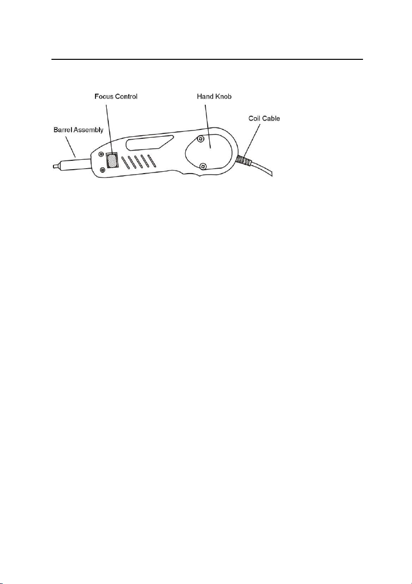
Structure/Parts
A. Analog Probe
This probe utilizes an analog CCD, which outputs an NTSC or a PAL
signal. The signal is routed through a 4-pin connector that routes
power into the probe, and the video signal out of the probe. This unit is
suitable for use with our hand held LCD display.
a 1. Barrel Assembly
The barrel assembly houses the optics which accommodates different
adapters, such as FC, SC, ST, LC, E2000, MTRJ and other customized PC
or APC adapters.
a 2. Focus Control
The default setting of magnification is 250x. When the figure shows on
monitor, screw the focus control to make it clearest.
- 3 -

Structure/Parts
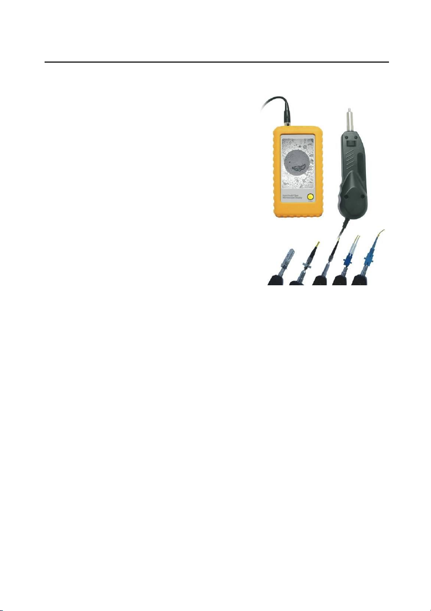
B. Hand-Held LCD Display
Standard: 3.5 inch Common Monitor
- 4 -

Structure/Parts
Optional: 3.5 inch Monitor-MEM
- 5 -

Structure/Parts
Monitor-MEM Function
1. Photo Snapping
When the ‘Power Switch’ is turned on, pressing ‘Camera’ would help
you take a photo for the inspection.
2. Data outputting
If you need to check the data saved in the SD card, you can either
connect the monitor via USB wire to your computer or take the SD
card out of the SD slot and read it with the card reader we offered.
These monitors can be powered by an output 110-240V DC/AC or a
rechargeable Li-ion battery equipped inside. Video input is dedicated
to PAL/NTSC formatted probe. All of the display’s controls are built into
the handle for easy access.
- 6 -

Structure/Parts
C. Standard Tips
- 7 -

Installation
Tip Assembly
Installing Tips on Probe
Assembly & Tip Installed Standard
Step 1
Locate tip you want to install and look at the threaded end. This
screw acts as a “key” and is already mounded with the Key Channel.
DO NOT try to screw the Key Channel off from the threaded Key,
which might destroy the whole probe.
Step 2
Slightly screw the Key that you need onto the Key Channel.
- 8 -

Installation
LCD Monitor Assembly & Controls
Using the LCD Display with the Probe
Connect the Probe to the Display
Step 1
Connect the cable from the probe to the monitor using the 4-pin
connector on the bottom of the monitor.
Step 2
Connect the AC power adapter/charger if necessary.
On/Off Control
(Toggle switch) Press upward to turn the unit on, press downward to
shut the unit off.
AC Power
Using the DC/AC power adapter has the following advantages:
Use external power (DC/AC power adapter/charger) to power the LCD
directly from a DC/AC power source, or charge the battery pack. Both
can be accomplished simultaneously.
- 9 -

General Information
Technical Specifications
Video Inspection Probe
Magnification 400x (9’’ Monitor) 250x (3.5’’ Monitor)
Resolution Ratio 0.5 um
Display 3.5’’ TFT-LCD, 960x240 pixels
Video Output NTSC / PAL
Weight/Dimensions 0.18 kg / 18 x 4 x 3.5 cm
Wire Length 1.2 M
Application
Adapter Type Description
25-U-M
(2.5mm UPC Male)
125-U-M
(1.25mm UPC Male)
25-A-M
(2.5mm APC Male)
125-A-M
(1.25mm APC Male)
25-U-F
(2.5mm UPC) Female)
LC-U-F
(LC UPC Female)
FC/SC/ST/E2000 patch cord UPC termination
LC/MU patch cord UPC termination
FC/SC/ST/E2000 patch cord APC termination
LC/MU patch cord APC termination
FC/SC/ST/E2000 UPC bulkhead
LC UPC bulkhead
- 10 -

General Information
SC-A-F
(SC APC Female)
FC-A-F
(FC APC Female)
LC-A-F
(LC APC Female)
Other Adapters can be offered on request.
Other Parts
Power Supply 12.6V rechargeable Li Battery
SC APC bulkhead
FC APC bulkhead
LC APC bulkhead
Monitor
Work/Storage Temp.
0.30 kg / 14.5 x 7.5 x 4 cm
0.40 kg / 17 x 10 x 4.5 cm
-20℃~+50℃ / -30℃~+60℃
Accessories
Type Function Description
Standard Accessories
Inspection Probe x1
3.5’’ monitor x1
Standard Accessories
25-U-M x1 ; 125-U-M x1
25-U-F x1 ; LC-U-F x1
Recharger ; Manual ; Carrying bag ; Li Battery
Optional Accessories
25-A-M ; 125-A-M ; SC-A-F ; FC-A-F ; LC-A-F
AV-USB 2.0 Converter
- 11 -

General Information
Warranty
We warrant this equipment against defects in material and
workmanship for a period of one year from the date of original
shipment. We also warrant that this equipment will meet applicable
specifications under normal use. During the warranty period, we will,
at our sole discretion, repair or replace for any defective product free
of charge should the equipment need to be repaired.
IMPORTANT
The warranty will become null and void if
• the equipment has been tampered with, repaired, or worked
upon by unauthorized individuals.
• the warranty label has been removed.
• product enclosure screws, other than those specified in this
manual, have been removed.
• the product enclosure has been opened, other than as explained
in this manual.
• the equipment serial number has been altered, erased, or
removed.
• the equipment has been misused, neglected, or damaged by
accident.
- 12 -
 Loading...