

Page 1
Page 2

DIRECTV Receiver
Owner’s
Manual
For DIRECTV Receiver Models:
SIR-S70
SIR-S75
Page 3
This symbol indicates high voltage is present inside.
It is dangerous to make any kind of contact with any part inside of this product.
This symbol alerts you that important literature concerning operation and
maintenance has been included with this product.
Note to CATV system installer: This reminder is provided to call CATV system installer’s attention to
Article 820-40 of the National Electrical Code that provides guidelines for proper grounding and,
in particular, specifies that the cable ground shall be connected to the grounding system of the
building as close to the point of cable entry as practical.
Caution: FCC regulations state that any unauthorized changes or modifications to this equipment
may void the user’s authority to operate it.
Caution: To prevent electric shock, match the wide blade of plug to the wide slot, and fully insert
the plug.
Important: One Federal Court has held that unauthorized recording of copyrighted TV programs is
an infringement of U.S. copyright laws.
To prevent damage which may result in fire or electric shock hazard, do not expose this appliance to
rain or moisture.
CAUTION
RISK OF ELECTRIC SHOCK
DO NOT OPEN
CAUTION: TO REDUCE THE RISK OF ELECTRIC SHOCK, DO
NOT REMOVE COVER (OR BACK). NO USER
SERVICEABLE PARTS INSIDE. REFER SERVICING TO
QUALIFIED SERVICE PERSONNEL.
Warning! Important Safety Instructions
Page 4
Warning! Important Safety Instructions
• Read all safety and operating instructions before operating this product.
• Keep the safety and operating instructions for future reference.
• Heed all warnings on the product and in the operating instructions.
• Follow all operating and use instructions.
• Unplug the product from the wall outlet before cleaning. Use a damp cloth; do not use liquid or aerosol
cleaners.
• Never add any attachments and/or equipment without approval of the manufacturer. Such additions can
increase the risk of fire, electric shock, or other personal injury.
• Do not use the product where contact with or immersion in water is a possibility, such as near bath tubs, sinks,
washing machines, swimming pools, etc.
• Do not place the product on an unstable cart, stand, tripod, bracket, or
table where it can fall. A falling product can cause serious injury to a child
or adult, and serious damage to the appliance. Use only with a cart, stand,
tripod, bracket, or table recommended by the manufacturer or sold with
the product. Follow the manufacturer’s instructions when mounting the
unit, and use a mounting accessory recommended by the manufacturer.
Move the product and cart with care. Quick stops, excessive force, and
uneven surfaces can make the unit and cart unsteady and likely to
overturn.
• Provide ventilation for the product. The unit is designed with slots in the
cabinet for ventilation to protect it from overheating. Do not block these
openings with any object, and do not place the product on a bed, sofa, rug, or other similar surface. Do not
place it near a radiator or heat register. If you place the product on a rack or bookcase, ensure that there is
adequate ventilation and that you have followed the manufacturer’s instructions for mounting.
• Operate your product only from the type of power source indicated on the marking label. If you are not sure of
the type of power supplied to your home, consult your appliance dealer or local power company.
• Use only a grounded or polarized outlet. For your safety, this product is equipped with a polarized alternating
current line plug having one blade wider than the other. This plug will fit into the power outlet only one way. If
you are unable to insert the plug fully into the outlet, try reversing the plug. If the plug still does not fit, contact
your electrician to replace your outlet.
• Protect the power cord. Power supply cords should be routed so that they will not be walked on or pinched by
objects placed on or against them. Pay particular attention to cords at plugs, convenience receptacles, and the
point where they exit from the unit.
• Unplug the product from the wall outlet and disconnect the antenna or cabling during a lightning storm or when
left unattended and unused for long periods of time. This will prevent damage to the unit due to lightning and
power-line surges.
Always be careful when using this product. To reduce the risk of fire, electrical shock,
and other injuries, keep these safety precautions in mind when installing, using, and
maintaining your DIRECTV Receiver.
Page 5
Warning! Important Safety Instructions
Warning! Important Safety Instructions
• Avoid overhead power lines. An outside antenna system should not be placed in the vicinity of
overhead power lines or other electric light or power circuits or where it can fall into such power lines
or circuits. When installing an outside antenna system, be extremely careful to keep from touching the
power lines or circuits. Contact with such lines can be fatal.
• Do not overload the wall outlet or extension cords. Overloading can result in fire or electric shock.
• Do not insert anything through the openings in the unit, where they can touch dangerous voltage
points or damage parts. Never spill liquid of any kind on the product.
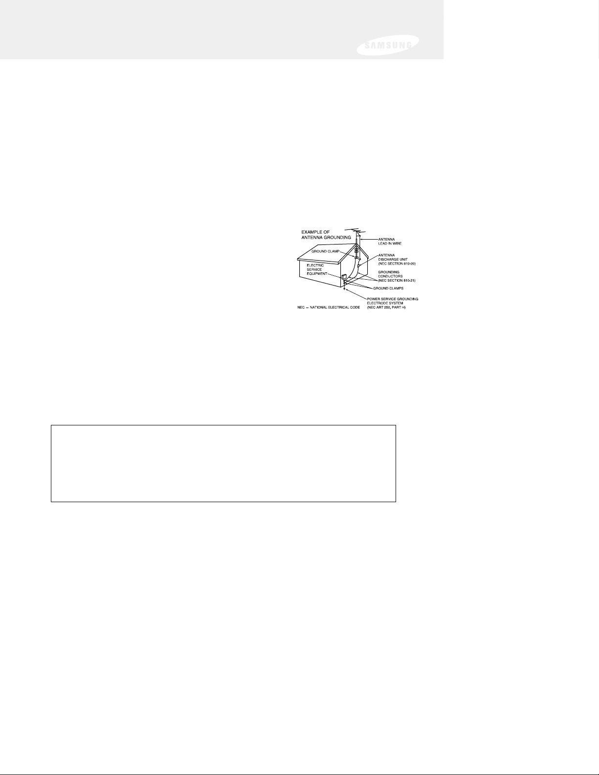
• Ground outdoor antennas. If an outside antenna is connected to the product, be sure the antenna is
grounded so as to provide some protection against voltage surges and built-up static charges. Section
810 of the National Electrical Code, ANSI/NFPA No.70-1984, provides information about proper
grounding of the mast and supporting structure, grounding of the lead-in wire to an antenna
discharge unit, size of grounding conductors, location of antenna discharge unit, connection to
grounding electrodes, and requirements for the grounding electrode.
• Do not attempt to service the product yourself. Refer all servicing to qualified service personnel.
Unplug the unit from the wall outlet and refer servicing to qualified service personnel under the
following
conditions:
- when the power-supply cord or plug is damaged
- if liquid has been spilled on the unit or if objects have fallen into
the unit
- if the product has been exposed to rain or water
- if the product does not operate normally by following the
operating instructions
- if the product has been dropped or the cabinet has been damaged
- when the product exhibits a distinct change in performance
• If you make adjustments yourself, adjust only those controls that are covered by the operating
instructions. Adjusting other controls may result in damage and will often require extensive work by a
qualified technician to restore the product to normal.
• When replacement parts are required, be sure the service technician uses replacement parts specified
by the manufacturer or those that have the same characteristics as the original part. Unauthorized
substitutions may result in additional damage to the unit.
• Upon completion of any service or repairs to this product, ask the service technician to perform safety
checks to determine that the product is in a safe operating condition.
This device complies with part 15 of the FCC Rules. Operation is subject to the
following two conditions:
(1) This device may not cause harmful interference, and
(2) This device must accept any interference that may cause undesired operation.
This satellite receiver provides display of television closed captioning in
accordance with §15.119 of the FCC rules.
Page 6

Notice
AAAAtttttttteeeennnnttttiiiioooonn
nn
Telephone Line Interruption
A continuous land-based phone line connection is required for DIRECTV®Pay Per View
functionality and sports subscriptions. Any calls generated by the DIRECTV Receiver are toll
free. These calls are typically made in the middle of the night; your phone is in use for
approximately 30 seconds.
Trademark and copyright statements
Samsung is a trademark of Samsung Electronics. ©2002 DIRECTV, Inc. DIRECTV, the Cyclone
Design logo and DIRECTV SPORTS are registered trademarks of DIRECTV, Inc., a unit of
Hughes Electronics Corp, and are used with permission. All other trademarks and service
marks are the property of their respective owners.
Manufactured under license from Dolby Laboratories. “Dolby” and the double-D symbol are
trademarks of Dolby Laboratories. Confidential Unpublished Works. ©1992–1997
Dolby Laboratories Inc. All rights reserved.
Macrovision Information
This equipment incorporates copyright protection technology that is protected by U.S. patents
and other intellectual property rights. Use of this copyright protection technology is granted
by Macrovision for home and other limited DBS IRD pay per view uses only. Reverse
engineering or disassembly is prohibited.
Program Recording Restrictions
Programming may be taped for home viewing only. All other taping is expressly prohibited.
Some programming may not be taped. An additional taping fee may be applied. Call your
program provider for details.
OOOOwwwwnnnneeeerrrr''''ssss RRRReeeeccccoooorrrrdd
dd
The model and serial numbers are located on the bottom of the DIRECTV Receiver. The
number for the Access Card is on the back of the card and on the carton label. Record these
numbers for reference when calling your sales or service representative regarding this product.
Model Number: ____________________________________
Serial Number: ____________________________________
Access Card Number: ______________________________
CCCCuuuussssttttoooommmmeeeerrrr SSSSuuuuppppppppoooorrrrtt
tt
For DIRECTV
®
Programming
For subscription information, or to resolve problems related to programming, call:
DIRECTV at 1-800-DIRECTV (1-800-347-3288) or visit the DIRECTV Web site
(DIRECTV.com).
For Installation
To arrange for the installation of your DIRECTV Receiver, call the dealer from whom
you purchased your system.
For Hardware
To resolve problems related to this DIRECTV Receiver, call
Samsung Customer Support at 1-800-522-2946.
Page 7

Warranty
SAMSUNG DIGITAL SATELLITE RECEIVER
LIMITED WARRANTY TO ORIGINAL PURCHASER
This SAMSUNG manufactured product, as supplied and distributed by Samsung Electronics
America, Inc. (SAMSUNG) and delivered new, in the original carton to the original
consumer purchaser, is warranted by SAMSUNG against manufacturing defects in
materials and workmanship for a limited warranty period of:
One (1) Year Parts and Labor*
(*90 Days Parts and Labor for Commercial Use)
This limited warranty begins on the original date of purchase, and is valid only on products
purchased and used in the United States. To receive warranty service, the purchaser must
contact SAMSUNG for problem determination and service procedures. Warranty service
can only be performed by a SAMSUNG authorized service center. The original dated bill of
sale must be presented upon request as proof of purchase to SAMSUNG or SAMSUNG’s
authorized service center. Transportation of the product to and from the service center is
the responsibility of the purchaser.
SAMSUNG will repair or replace this product, at our option and at no charge as stipulated
herein, with new or reconditioned parts or products if found to be defective during the
limited warranty period specified above. All replaced parts and products become the
property of SAMSUNG and must be returned to SAMSUNG. Replacement parts and
products assume the remaining original warranty, or ninety (90) days, whichever is longer.
SAMSUNG’s obligations with respect to software products distributed by SAMSUNG under
the SAMSUNG brand name are set forth in the applicable end user license agreement.
Non-SAMSUNG hardware and software products are provided on an “AS IS” basis.
However, non-SAMSUNG manufacturers, suppliers, publishers, and service providers may
provide their own warranties.
This limited warranty covers manufacturing defects in materials and workmanship
encountered in normal, and except to the extent otherwise expressly provided for in this
statement, noncommercial use of this product, and shall not apply to the following,
including, but not limited to: damage which occurs in shipment; delivery and installation;
applications and uses for which this product was not intended; altered product or serial
numbers; cosmetic damage or exterior finish; accidents, abuse, neglect, fire, water,
lightning or other acts of nature; use of products, equipment, systems, utilities, services,
parts, supplies, accessories, applications, installations, repairs, external wiring or connectors
not supplied and authorized by SAMSUNG, or which damage this product or result in
service problems; incorrect electrical line voltage, fluctuations and surges; customer
Page 8

Warranty
adjustments and failure to follow operating instructions, cleaning, maintenance and
environmental instructions that are covered and prescribed in the instruction book;
product removal or reinstallation; reception problems and distortion related to noise,
echo, interference or other signal transmission and delivery problems. SAMSUNG
does not warrant uninterrupted or error-free operation of the product.
THERE ARE NO EXPRESS WARRANTIES OTHER THAN THOSE LISTED AND DESCRIBED
ABOVE, AND NO WARRANTIES WHETHER EXPRESS OR IMPLIED, INCLUDING, BUT
NOT LIMITED TO, ANY IMPLIED WARRANTIES OF MERCHANTABILITY OR FITNESS
FOR A PARTICULAR PURPOSE, SHALL APPLY AFTER THE EXPRESS WARRANTY
PERIODS STATED ABOVE, AND NO OTHER EXPRESS WARRANTY OR GUARANTY
GIVEN BY ANY PERSON, FIRM OR CORPORATION WITH RESPECT TO THIS PRODUCT
SHALL BE BINDING ON SAMSUNG. SAMSUNG SHALL NOT BE LIABLE FOR LOSS OF
REVENUE OR PROFITS, FAILURE TO REALIZE SAVINGS OR OTHER BENEFITS, OR ANY
OTHER SPECIAL, INCIDENTAL OR CONSEQUENTIAL DAMAGES CAUSED BY THE USE,
MISUSE OR INABILITY TO USE THIS PRODUCT, REGARDLESS OF THE LEGAL THEORY
ON WHICH THE CLAIM IS BASED, AND EVEN IF SAMSUNG HAS BEEN ADVISED OF
THE POSSIBILITY OF SUCH DAMAGES. NOR SHALL RECOVERY OF ANY KIND AGAINST
SAMSUNG BE GREATER IN AMOUNT THAN THE PURCHASE PRICE OF THE PRODUCT
SOLD BY SAMSUNG AND CAUSING THE ALLEGED DAMAGE. WITHOUT LIMITING THE
FOREGOING, PURCHASER ASSUMES ALL RISK AND LIABILITY FOR LOSS, DAMAGE OR
INJURY TO PURCHASER AND PURCHASER’S PROPERTY AND TO OTHERS AND THEIR
PROPERTY ARISING OUT OF THE USE, MISUSE OR INABILITY TO USE THIS PRODUCT
SOLD BY SAMSUNG NOT CAUSED DIRECTLY BY THE NEGLIGENCE OF SAMSUNG.
THIS LIMITED WARRANTY SHALL NOT EXTEND TO ANYONE OTHER THAN THE
ORIGINAL PURCHASER OF THIS PRODUCT, IS NONTRANSFERABLE AND STATES YOUR
EXCLUSIVE REMEDY.
Some states do not allow limitations on how long an implied warranty lasts, or the
exclusion or limitation of incidental or consequential damages, so the above limitations
or exclusions may not apply to you. This warranty gives you specific legal rights, and you
may also have other rights which vary from state to state.
To obtain warranty hardware service, please contact SAMSUNG at:
SAMSUNG CUSTOMER SERVICE
400 VALLEY ROAD, SUITE 201, MT ARLINGTON, NJ 07856, TEL: 973-601-6000, F AX: 973-601-6001
1-800-522-2946 and SAMSUNGUSA.COM
061501
Page 9

Table of Contents
Chapter 1: Getting Started ......................................................................5
Box contents ...................................................................................5
Front panel controls and lights ........................................................7
Back of the DIRECTV Receiver ........................................................9
Installing the batteries in the remote control...................................11
Inserting the Access card ...............................................................12
Chapter 2: Setting up and connecting ..................................................13
Jacks and cables ............................................................................13
Before making connections ............................................................15
Choosing a connection ..................................................................16
Connection option A: ................................................................... 17
DIRECTV Receiver to TV with RF cable only
Connection option B: .....................................................................19
DIRECTV Receiver to TV with A/V cables
Connection option C: ....................................................................21
DIRECTV Receiver to TV and VCR with RF cables only
Connection option D: ....................................................................23
DIRECTV Receiver to TV and VCR with A/V cables
Connection option E: .....................................................................25
DIRECTV Receiver to TV and A/V receiver
Connection option F: .....................................................................27
DIRECTV Receiver to TV with
Component Video inputs and digital A/V receiver
Connecting the VCR control cable (model SIR-S75 only)................29
Turning on the DIRECTV Receiver for the first time........................29
Adjusting up the satellite dish .........................................................30
Testing your DIRECTV Receiver......................................................36
Activating your DIRECTV account..................................................38
Upgrades........................................................................................38
1
Page 10

Chapter 3: Watching TV........................................................................39
Remote control overview................................................................39
Changing channels.........................................................................41
Adjusting the volume .....................................................................41
Getting help ...................................................................................41
Getting information on the TV program you are watching.............41
Finding out what’s on: the Guides..................................................45
Searching for programs in the Guide..............................................54
Choosing an alternate audio format for a program.........................57
Changing the User setting..............................................................57
Pay per view programs...................................................................58
Chapter 4: Program reminders and recording timers.............................63
Setting up the VCR control (model SIR-S75 only)...........................63
Scheduling program reminders and recording timers......................65
Reviewing and modifying reminders and recording timers..............66
Chapter 5: User profiles.........................................................................69
User profiles basics.........................................................................69
Editing user profile names...............................................................70
Editing channel lists........................................................................72
Setting ratings limits.......................................................................74
Allowing or blocking pay per view purchases.................................80
Setting a pay per view spending limit.............................................81
Setting the screen color and translucency.......................................82
Setting the current user profile.......................................................83
Locking and unlocking your DIRECTV System................................83
2
Page 11

Table of Contents
Chapter 6: Settings, preferences, upgrades, and extras.........................85
Reading your mail ..........................................................................85
Setting system preferences.............................................................86
Reviewing and controlling caller ID ................................................92
Setting the Local Time options.......................................................94
Installing a new Access Card ..........................................................96
Viewing important information and a list of features .....................97
supported by your DIRECTV Receiver
Viewing information on automatic system upgrades ......................99
Viewing fun system extras............................................................100
Chapter 7: Programming the remote control.......................................101
Programming the remote control..................................................101
Operating a device with your programmed remote control..........102
Code lists......................................................................................103
3
Page 12

Chapter 8: Troubleshooting .................................................................109
Appendix: Specifications......................................................................111
Specifications for DIRECTV Receiver model SIR-S70 .....................111
Specifications for DIRECTV Receiver model SIR-S75 .....................112
Index....................................................................................................113
4
Page 13
Chapter 1: Getting started
This chapter tells you everything you need to know before you start setting up and
using your DIRECTV Receiver. It includes information on:
• Box contents
• Front panel controls and lights
• Back of the DIRECTV Receiver
• Installing the batteries in the remote control
• Inserting the Access Card
5
Box contents
Welcome! The first step in setting up your DIRECTV Receiver is to unpack the box
and familiarize yourself with its contents. This manual covers two models of
DIRECTV Receiver: the SIR-S70 and the SIR-S75.
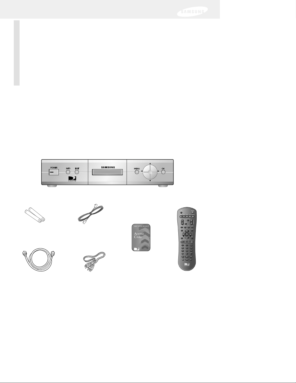
DIRECTV Receiver (SIR-S70)
RJ-11
Telephone cord
A/V cable
Remote control
Access Card
AAA size batteries
RF coaxial cable
Box contents for the SIR-S70
If you are missing any items, contact your Samsung dealer.
Page 14
6
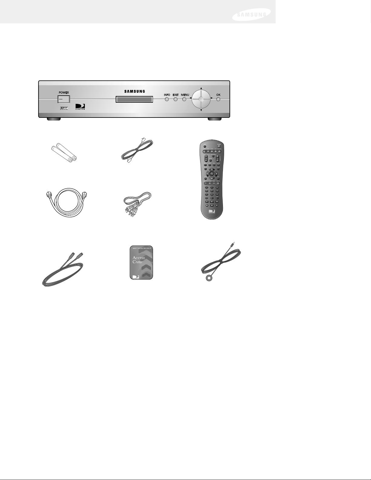
Box contents for the SIR-S75
If you are missing any items, contact your Samsung dealer.
AAA size batteries
DIRECTV Receiver (SIR-S75)
RJ-11
Telephone cord
A/V cable
Remote control
RF coaxial cable
Access Card
VCR control cable
S-Video cable
Page 15
Chapter 1: Getting started
7
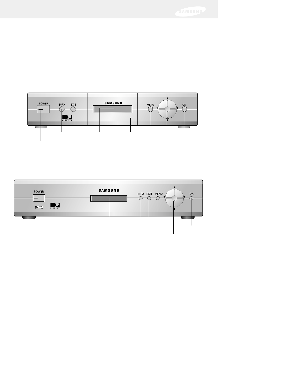
Front panel controls and lights
Now that you’ve unpacked the box, take a moment to take a look at the
buttons and lights on the front of your DIRECTV Receiver.
POWER button
and light
OK
MenuEXIT
ArrowsRemote
control sensor
INFO
SIR-S75
SIR-S70
POWER button
and light
OKMenu
EXIT Arrows
Remote control sensor INFO
Access Card
door
Page 16

Chapter 1: Getting started
8
POWER Button and light
Push this button to turn your DIRECTV Receiver on or off. The light glows when
power is on.
Remote control sensor
Point your remote control at this sensor when operating your receiver.
Access Card door (Model SIR-S70 only)
This door covers the Access Card slot. This slot holds the Access Card (which allows
you to view DIRECTV
®
programming). The Access Card slot is on the rear panel on
model SIR-S75.
INFO
Push this button to display TV program information.
EXIT
Push this button to clear on-screen displays and return to TV program viewing.
MENU
Push this button to display the Main Menu.
Arrows
Push these buttons to navigate left, right, up, or down in the on-screen Guide and
menu system.
OK
Push this button to select a highlighted item in the on-screen Guide and menu system.
Page 17
Chapter 1: Getting started
9
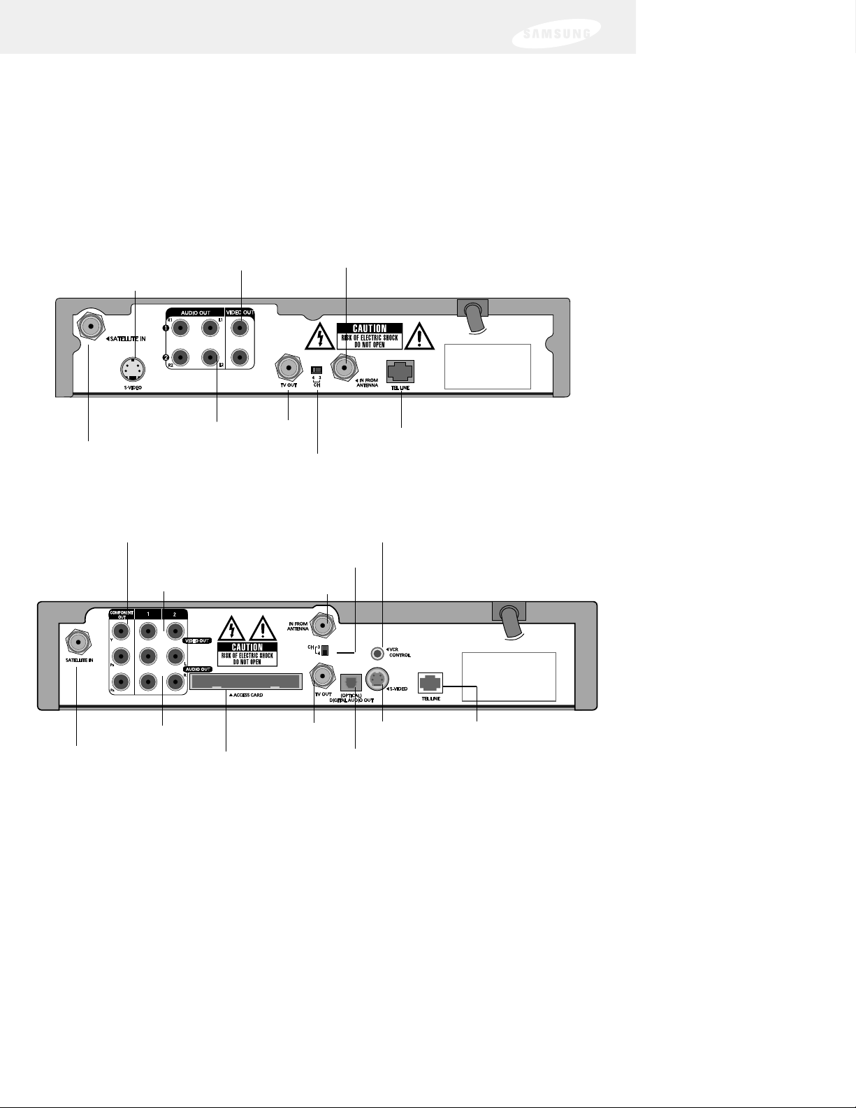
Back of the DIRECTV Receiver
The diagram below illustrates the location of the input and output jacks on the
back of the receiver. These illustrations may help you as you set up your
DIRECTV Receiver. Step-by-step setup instructions appear in Chapter 2.
Antenna In
Video Out
Channel 3/4 switch
VCR control
Telephone lineS-VIDEO Out
Digital Audio Out
TV OUT
Access Card slot
Audio Out
Component Out(Y, Pb, Pr video)
SATELLITE IN
SIR-S75
SIR-S70
Antenna InVideo Out
SATELLITE IN
Channel 3/4 switch
Telephone line
S-VIDEO Out
TV OUT
Audio Out
Page 18

Chapter 1: Getting started
10
Satellite In
The RG-6 cable from the satellite dish connects to this jack.
Antenna In
The cable from an off-air TV antenna (not from the satellite dish) connects to
this jack.
Video Out
Using a standard video cable, this jack connects your DIRECTV Receiver to
your TV or VCR.
Audio Out
Using standard stereo audio cables, these jacks connect the DIRECTV
Receiver to your TV or VCR.
S-Video Out
This jack connects your DIRECTV Receiver to a TV or VCR that accepts
S-Video input.
Component Out (Y, Pb, Pr video) (SIR-S75 only)
Using standard A/V cables, these jacks connect your DIRECTV Receiver to a
TV or VCR that accepts high-quality (“component”) video input.
Digital audio out (SIR-S75 only)
Using an optical digital audio cable, this jack allows you to connect your
DIRECTV Receiver to an audio receiver that accepts optical digital audio
input.
TV Out
Using an RF coaxial cable, this jack connects the DIRECTV Receiver to your
TV or VCR.
Channel 3/4 switch
This switch sets the channel for viewing the TV Out signal on your TV.
Telephone line
A telephone line connected to this jack allows you to order
pay per view programming.
VCR control (SIR-S75 only)
The VCR control cable connects to this jack.
Access Card slot (model SIR-S75 only)
This slot holds the Access Card (which allows you to view
DIRECTV
®
programming). The Access Card slot is behind the Access Card
door on the front of model SIR-S70.
Page 19
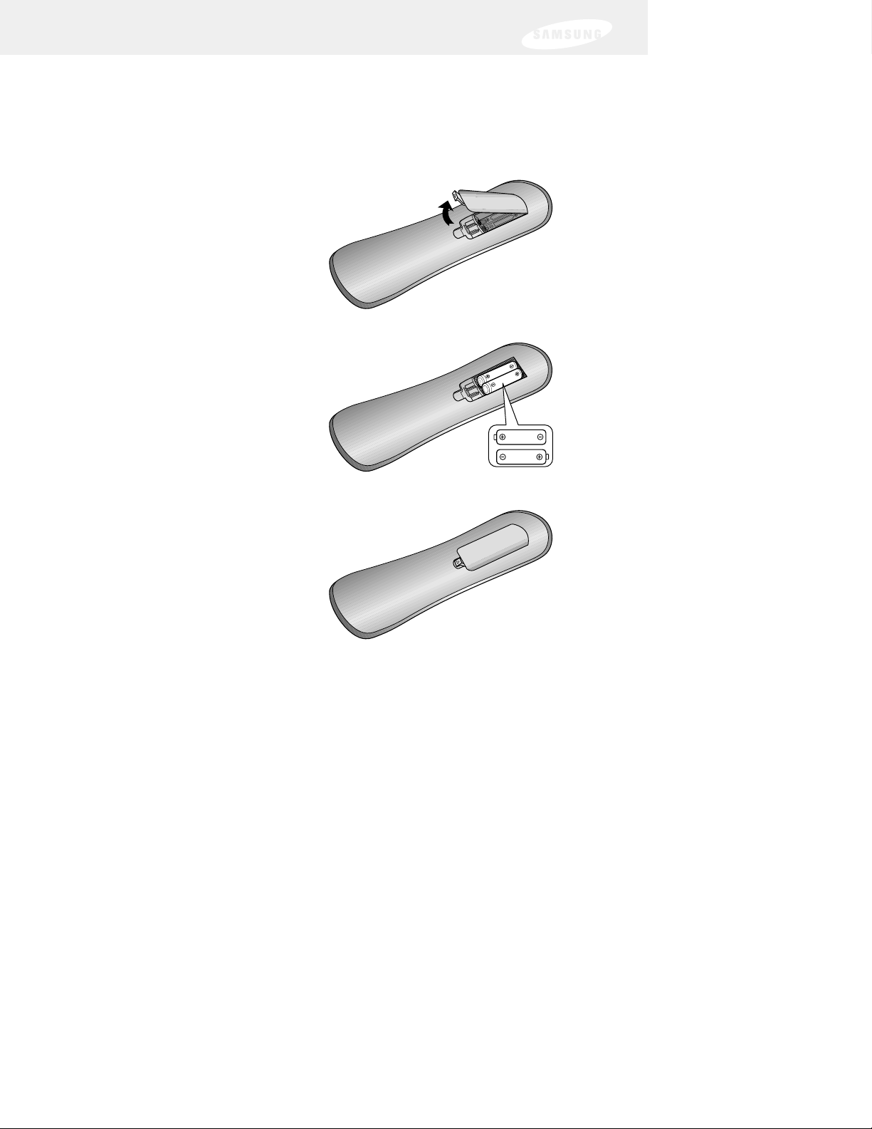
Installing the batteries in the remote control
You’ve unpacked the receiver and reviewed its front and back panels. Now it’s time to
start setting up. The first step is to install the batteries in your remote control.
1 Unlatch the battery compartment cover
on the back of remote control.
2 Insert 2 AAA batteries as shown,
making sure the + and – ends of each
battery line up with the corresponding
marks in the battery compartment.
3 Snap the cover back onto the remote
control.
4 Test the remote control to make sure the batteries have been inserted correctly. Press
the DIRECTV button and make sure the button lights up. If it does not light up,
check the orientation of the batteries.
Note: Alkaline batteries are strongly recommended for this remote control.
Chapter 1: Getting started
11
Page 20
Chapter 1: Getting started
12
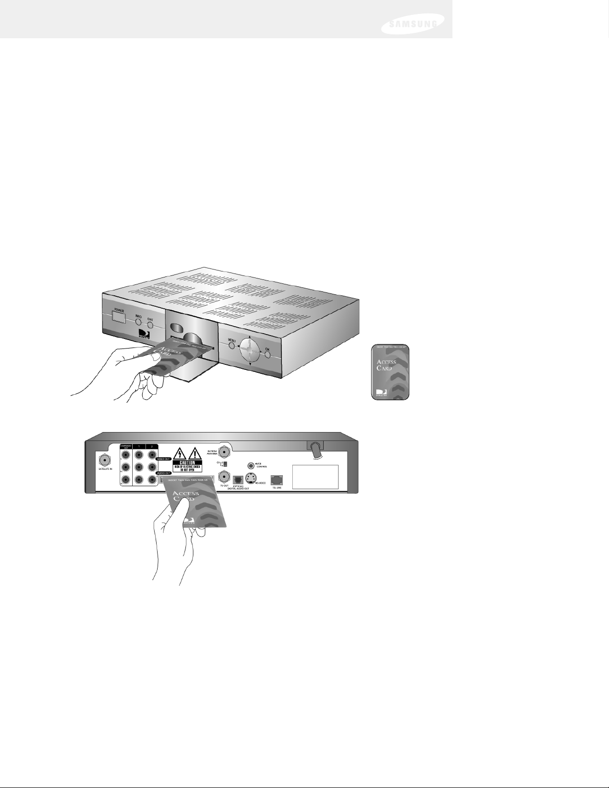
Inserting the Access Card
The next step is to insert your Access Card into your receiver. (You will not be able to view
DIRECTV®programming unless the Access Card is properly inserted into the DIRECTV
Receiver.) For some receivers, the card may already be inserted when you unpack the box.
1 Locate the ACCESS CARD slot.
On model SIR-S70 the slot is located on the front of the DIRECTV Receiver, behind
the Access Card door.
On model SIRS75 the slot is located on the back of the DIRECTV Receiver.
2 Insert the Access Card.
Make sure the side with the bar code is facing down, and the arrow is pointing away
from you.
The Access Card should only be removed when replacing the card with a new one
provided by DIRECTV or your program provider.
Model SIR-S70
Model SIR-S75
Access Card
(Top view)
Page 21
13
Jacks and cables
The illustrations on these pages show the various types of jacks and cables used to
connect your DIRECTV Receiver. If you are unfamiliar with these jacks and cables,
take a moment to review them before starting the step-by-step connection process.
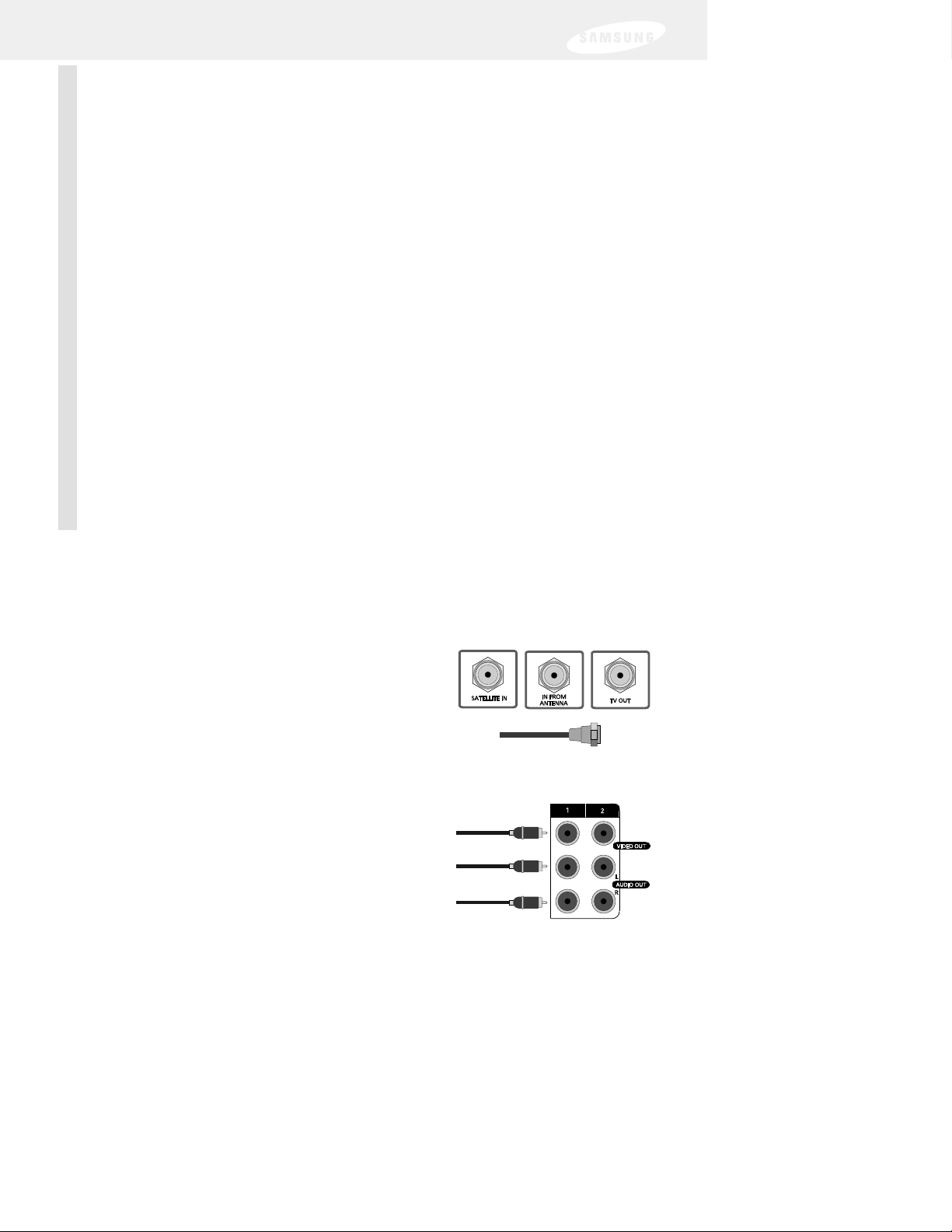
RF jacks and coaxial cable
The TV OUT RF jack on the DIRECTV Receiver uses a
coaxial cable to connect to your TV or VCR. This jack
provides monaural sound and a good TV picture. An
RF jack is also used for TV antenna connection (IN
FROM ANTENNA), and using an RG-6 coaxial cable,
for the satellite dish (SATELLITE IN) input connection.
Audio/Video jacks and cables (RCA-type)
Audio/Video jacks and cables provide stereo sound
and a better TV picture than RF jacks and cables. Use
these jacks and cables to connect your receiver to a
TV, VCR, or to other components such as a stereo
receiver or amplifier. The audio/video jacks on the
back of the receiver and the audio/video cable
connectors are color coded (yellow for video, red for
right audio, and white for left audio).
Chapter 2: Setting up and connecting
This chapter explains how to setup and start using your DIRECTV Receiver.
Contents include:
• Jacks and cables
• Before making connections
• Choosing a connection
• Connection option A: DIRECTV Receiver to TV with RF cable only
• Connection option B: DIRECTV Receiver to TV with A/V cables
• Connection option C: DIRECTV Receiver to TV and VCR with
RF cables only
•
Connection option D: DIRECTV Receiver to TV and VCR with A/V cables
• Connection option E: DIRECTV Receiver to TV and A/V receiver
• Connection option F (SIR-S75 only): DIRECTV Receiver to TV with Component
Video inputs and digital A/V receiver
• Connecting the VCR control cable (model SIR-S75 only)
• Turning on the DIRECTV Receiver for the first time
• Adjusting the satellite dish
• Testing your DIRECTV Receiver
• Activating the DIRECTV account
• DIRECTV
®
service upgrades
Page 22
14
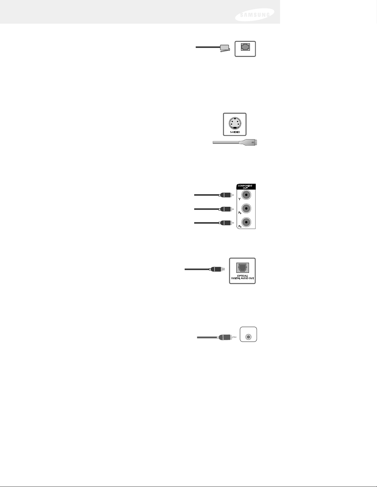
Telephone jack and cord
The TEL LINE jack and the included telephone cord connect
your DIRECTV Receiver to a phone line. If your home does
not have RJ-11 type phone jacks, please contact your phone
company to get one installed.
A continuous land-based phone line connection is required for DIRECTV
®
Pay Per
View functionality and DIRECTV SPORTS
®
subscriptions. Any calls generated by the
DIRECTV Receiver are toll-free. These calls are typically made in the middle of the
night; your phone is in use for approximately 30 seconds.
S-Video jack and cable (cable included with model SIR-S75 only)
S-Video cables and jacks are used to connect the DIRECTV
Receiver to TVs, VCRs, and other video equipment equipped
with S-Video input jacks. S-Video connections provide a highquality TV picture (better than RCA-type A/V jacks and cables).
Unlike the round RCA-type connectors, S-Video connectors
must be correctly aligned before you can plug in the cable. (This
cable carries the video signal only; use with A/V cables for the audio signal.)
Component video jacks and cables (cable not included, jack on model
SIR-S75 only)
The three-cable component video cables and jacks (also
referred to as “Y, Pb, Pr”) are used to connect the
DIRECTV Receiver to TVs, VCRs, A/V receivers and other
video equipment equipped with component video input
jacks. Component video connections provide a TV picture
superior to S-Video connections. (These cables carry the
video signal only; use with A/V cables for the audio signal.)
Optical digital audio jack and cable (cable not included, jack on model
SIR-S75 only)
Optical digital jacks and cables use light to send digital
audio data to A/V receivers equipped to receive and
interpret this data. The uniquely shaped connectors on
the jacks and cables must be aligned before you can
plug in the cable. (Note that the jacks and cables may
be covered by protective caps which you must remove
before making the connection.)
VCR control jack and cable (jack and cable included on SIR-S75 only)
The VCR control jack and cable allow your model SIR-S75
DIRECTV Receiver to send signals to your VCR’s remote
sensor, giving you the ability to program your VCR to tape
programs for you using simple on-screen controls.
TEL LINE
TEL LINE
VCR
CONTROL
VCR
CONTROL
Page 23

Before making connections
The next steps are to determine which connection option you should use and then to
make the necessary connections. Before you begin, please note the following
important safety and setup tips.
Protect your components from power surges
• Always turn off and unplug your DIRECTV Receiver, TV, and any other
components before connecting or disconnecting any of the cables.
Position all cables correctly to avoid audio hum
or interference
• After connecting the components, please run the audio/video cables along the
side of the TV set, rather than straight down the back of the TV.
• Make sure that all cables are plugged or screwed tightly into their jacks.
• Please make sure that all antennas and cables are properly grounded.
• Whenever possible, route audio and video cables away from power cords.
Protect your components from overheating
• Do not block ventilation holes in the top of the DIRECTV Receiver, or any other
components. Make sure to position the components so that air can circulate
freely.
• If you are positioning the components in a stand or rack, make sure to allow for
proper ventilation.
• Do not stack components.
• If you have a stereo amplifier or receiver as a system component, please place it
on the top shelf or top rack so that hot air rising from it will not flow around other
components.
Make strong connections
• Make sure you securely connect cables when making connections. When a tight
fit makes a secure connection difficult, you can sometimes make it easier by
gently twisting the cable-end while pushing it onto the jack. (Important: never
twist S-Video or Optical Digital Audio cables — they have specially shaped ends
that must be correctly oriented before connecting.)
Avoid cable damage
• Never kink, bend, or twist optical digital audio cables; doing so might break the
fragile optical fibers they contain, rendering them unable to carry a signal.
Chapter 2: Setting up and connecting
15
Page 24

Chapter 2: Setting up and connecting
16
Choosing a connection
Your DIRECTV Receiver supports a variety of connection possibilities to ensure that
it is compatible with whatever type of TV, VCR, or A/V receiver you might have.
This manual describes six different setup possibilities in detail. The one that is right
for you depends on what type of A/V equipment you have in addition to your
DIRECTV Receiver. To get the best audio and video possible with your particular set
of A/V equipment, use these pages to choose the connection option that most
closely matches your situation.
Option A: DIRECTV Receiver to TV with RF cable only
Option A is the most simple setup option. If you are not planning on
using a VCR and your TV has no A/V connectors, use this option.
(Turn to page 17 now.)
Option B: DIRECTV Receiver to TV with A/V cables
Option B is also for people not planning on using a VCR, but this
option improves the sound and video quality by making the
connections using A/V cables. If you are not planning to use a VCR,
but your TV does have RCA-type A/V input jacks, use connection
Option B. (Turn to page 19 now.)
Option C: DIRECTV Receiver to TV and VCR with RF cables only
Option C is the simplest connection option that includes a VCR. If you
want to connect your DIRECTV Receiver to a TV and VCR, and your
TV or VCR does not have A/V jacks, use connection Option C. (Turn
to page 21 now.)
Option D: DIRECTV Receiver to TV and VCR with A/V cables
Option D also allows you to connect the DIRECTV Receiver to a TV
and VCR, but Option D provides improved sound and video quality
over Option C. If you are planning to connect your DIRECTV Receiver
to a TV and VCR which both have A/V jacks,use connection Option
D. (Turn to page 23 now.)
Option E: DIRECTV Receiver to TV and A/V receiver
Option E shows you how to connect the DIRECTV Receiver to an A/V
system that includes an A/V receiver. If you plan to use an A/V
receiver with your DIRECTV Receiver and TV, use connection Option
E. (Turn to page 25 now.)
Option F: DIRECTV Receiver to TV with component video inputs and
Digital A/V receiver (SIR-S75 only)
Option F also shows you how to connect the DIRECTV Receiver to an
A/V setup that includes a TV and an A/V receiver. In Option F,
however, the A/V receiver supports optical digital audio input, and the
TV supports component (Y, Pb, Pr) video input. If this matches your
situation, use connection Option F. (Turn to page 27 now.)
Page 25

Chapter 2: Setting up and connecting
17
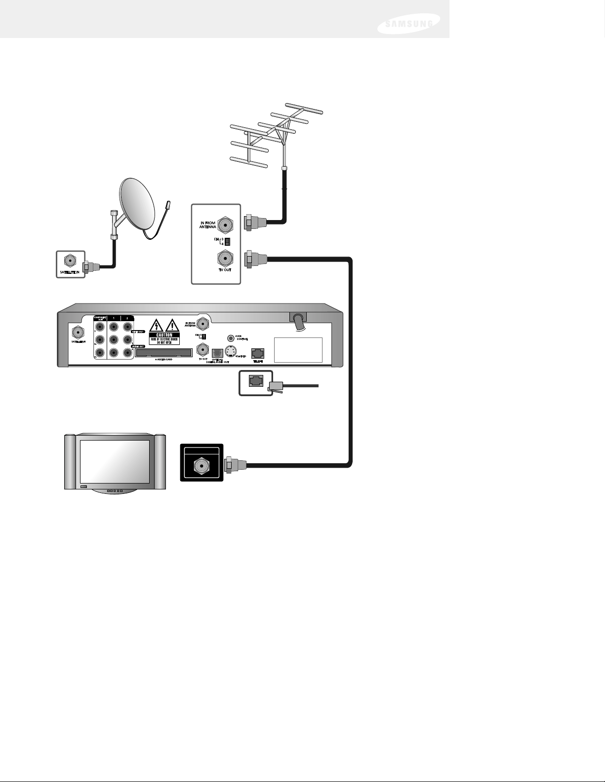
Connection option A:
DIRECTV Receiver to TV with RF cable only
If connection option A best matches your needs,
follow these steps:
1 Make sure your TV and DIRECTV Receiver are turned off and unplugged.
2 Connect the RG-6 coaxial cable running from your satellite dish to the
SATELLITE IN jack on the back of your DIRECTV Receiver.
3 Connect the coaxial cable running from your cable TV system or
off-air TV antenna to the IN FROM ANTENNA jack on the back of
the DIRECTV Receiver.
4 Connect the supplied phone cord to a telephone wall jack and to the
TEL LINE jack on the back of the DIRECTV Receiver.
5 Connect the supplied coaxial cable to the Antenna In jack on your TV and to
the TV OUT jack on the back of the DIRECTV Receiver.
6 Plug in the power cords for your DIRECTV Receiver and TV.
To watch DIRECTV®programming
To watch DIRECTV®programming, tune your TV to channel 3 or 4 (depending
on the position of the CH 3/4 switch on the back of your DIRECTV Receiver).
Channel 3 is the default setting.
Next Step
Now turn to page 29 to start using your DIRECTV Receiver.
Page 26
ANTENNA IN
TEL LINE
Chapter 2: Setting up and connecting
18
Note: DIRECTV Receiver model SIR-S75 shown;
connections are the same for model SIR-S70.
DIRECTV Receiver
TEL LINE
ANTENNA IN
TV
Page 27

Chapter 2: Setting up and connecting
19
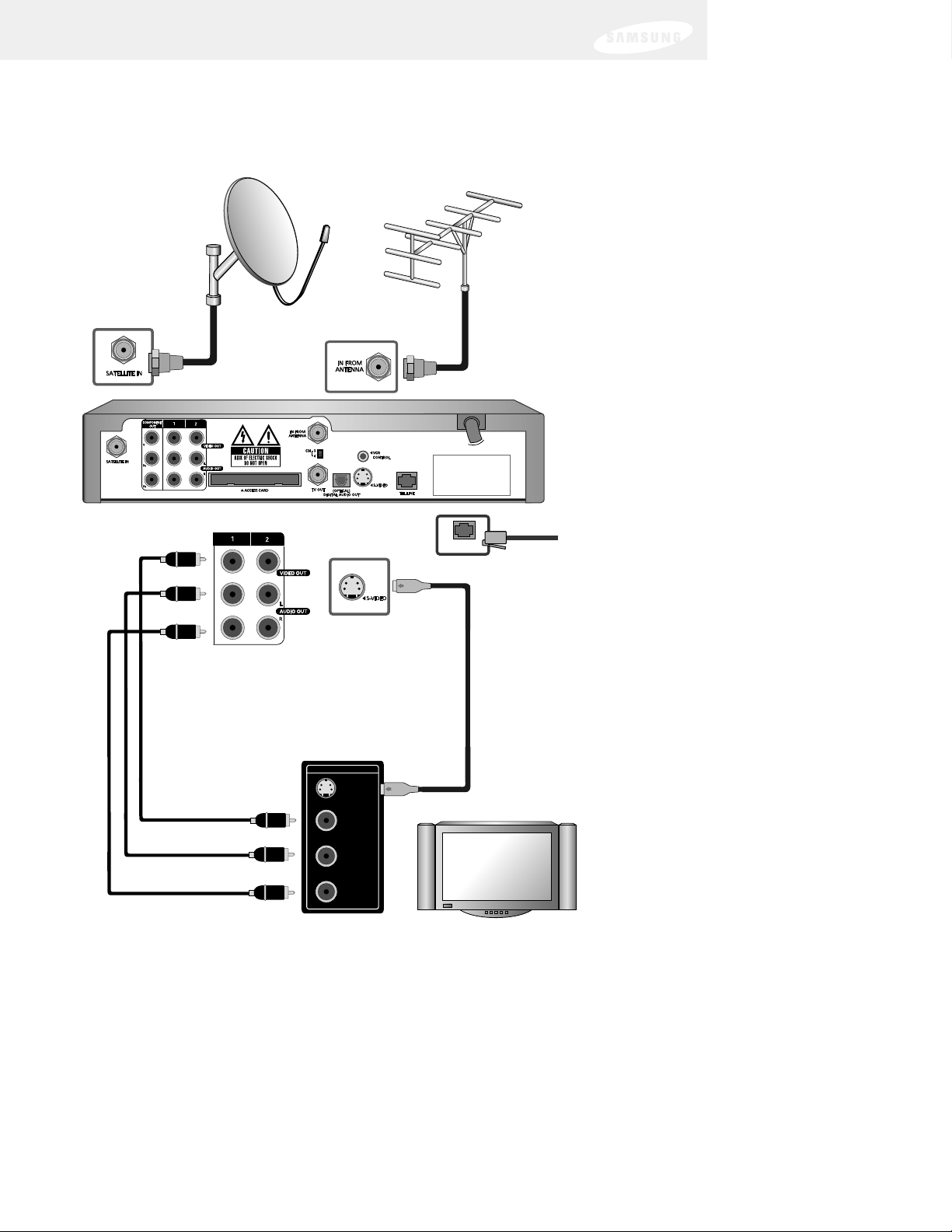
Connection option B:
DIRECTV Receiver to TV with A/V cables
If connection option B best matches your needs,
follow these steps:
1 Make sure your TV and DIRECTV Receiver are turned off and unplugged.
2 Connect the RG-6 coaxial cable running from your satellite dish to the
SATELLITE IN jack on the back of your DIRECTV Receiver.
3 Connect the coaxial cable running from your cable TV system or
off-air TV antenna to the IN FROM ANTENNA jack on the back of
the DIRECTV Receiver.
4 Connect the supplied phone cord to a telephone wall jack and to the
TEL LINE jack on the back of the DIRECTV Receiver.
5 Matching like colors, connect the supplied A/V cable to the AUDIO OUT
and VIDEO OUT jacks on the back of the DIRECTV Receiver.
6 Connect the other ends of the A/V cables to the audio and video input jacks
on your TV. Be sure to connect the outputs on the DIRECTV Receiver to
corresponding inputs on your TV (video out to video in, left audio out to left
audio in, right audio out to right audio in).
7 (Optional) if your TV has an S-Video input jack, connect one end of an S-
Video cable to the S-VIDEO jack on the back of the DIRECTV Receiver.
Connect the other end of this cable to the S-Video In jack on the back of
your TV. This step is optional; it provides improved picture quality on
some TVs.
8 Plug in the power cords for your DIRECTV Receiver and TV.
To watch DIRECTV®programming
Set your TV to the appropriate input mode. This is a setting on your TV usually
controlled by a Video, Input, or Mode button. See the manual for your TV for
instructions.
Next Step
Now turn to page 29 to start using your DIRECTV Receiver.
Page 28
TEL LINE
Chapter 2: Setting up and connecting
20
Note: DIRECTV Receiver model SIR-S75 shown;
connections are the same for model SIR-S70.
DIRECTV Receiver
TEL LINE
TV INPUT
S-VIDEO
VIDEO
L
AUDIO
R
TV
Page 29

Chapter 2: Setting up and connecting
21
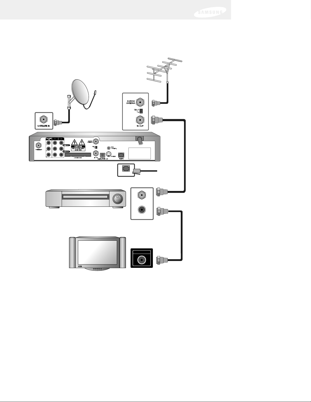
Connection option C:
DIRECTV Receiver to TV and VCR with RF cables only
If connection option C best matches your needs,
follow these steps:
1 Make sure your TV, VCR, and DIRECTV Receiver are turned off and
unplugged.
2 Connect the RG-6 coaxial cable running from your satellite dish to the
SATELLITE IN jack on the back of your DIRECTV Receiver.
3 Connect the coaxial cable running from your cable TV system or
off-air TV antenna to the IN FROM ANTENNA jack on the back of
the DIRECTV Receiver.
4 Connect the supplied phone cord to a telephone wall jack and to the
TEL LINE jack on the back of the DIRECTV Receiver.
5 Connect one end of the supplied coaxial cable to the TV OUT connector on
the back of the DIRECTV Receiver. Connect the other end of this cable to the
Antenna In jack on your VCR.
6 Connect one end of another coaxial cable (not included) to the TV Out RF
jack on the back of your VCR. Connect the other end of this cable to the
Antenna In jack on the back of your TV.
7 (Optional, model SIR-S75 only) go to page 29 to hook up the VCR control.
8 Plug in the power cords for your TV, VCR, and DIRECTV Receiver.
To watch DIRECTV®programming
With your VCR in TV mode or powered off, tune your TV to channel 3 or 4
(depending on the position of the CH 3/4 switch on the back of your DIRECTV
Receiver). Channel 3 is the default setting. The position of the CH 3/4 switch on
your DIRECTV Receiver should match the setting of the similar CH 3/4 switch on
your VCR.
Next Step
Now turn to page 29 to start using your DIRECTV Receiver.
Page 30
TV OUT
TEL LINE
ANTENNA IN
Chapter 2: Setting up and connecting
22
Note: DIRECTV Receiver model SIR-S75 shown;
connections are the same for model SIR-S70.
DIRECTV Receiver
TEL LINE
ANTENNA IN
VCR
TV
TV OUT
ANTENNA IN
Page 31

Chapter 2: Setting up and connecting
23
Connection option D:
DIRECTV Receiver to TV and VCR with A/V cables
If connection option D best matches your needs,
follow these steps:
1
Make sure your TV, VCR, and DIRECTV Receiver are turned off and unplugged.
2 Connect the RG-6 coaxial cable running from your satellite dish to the
SATELLITE IN jack on the back of your DIRECTV Receiver.
3 Connect the coaxial cable running from your cable TV system or
off-air TV antenna to the IN FROM ANTENNA jack on the back of
the DIRECTV Receiver.
4 Connect the supplied phone cord to a telephone wall jack and to the
TEL LINE jack on the back of the DIRECTV Receiver.
5 Matching like colors, connect the supplied A/V cables to the AUDIO OUT and
VIDEO OUT jacks on the back of the DIRECTV Receiver.
6 Connect the other ends of these A/V cables to the audio and video input jacks
on your VCR. Be sure to connect the A/V jacks on the DIRECTV Receiver to
corresponding inputs on your VCR (video out to video in, left audio out to left
audio in, right audio out to right audio in).
7 Matching like colors, connect another set of A/V cables (not included) to the
other set of audio and video output jacks on the back of the DIRECTV
Receiver. Connect the other ends of these cables to the audio and video input
jacks on your TV. Be sure to connect the outputs on the DIRECTV Receiver to
corresponding inputs on your TV.
8 (Optional) if your TV and VCR both have S-Video jacks, you can also make the
S-Video connections shown in the illustration. This step is optional; it provides
improved picture quality.
9 (Optional, model SIR-S75 only) go to page 29 to hook up the VCR control.
10 Plug in the power cords for your TV, VCR, and DIRECTV Receiver.
To watch DIRECTV®programming
Set your TV to the appropriate input mode. (This is a setting on your TV usually
controlled by a Video, Input, or Mode button. See your TV manual for help.) Also
make sure your VCR is turned on.
Next Step
Now turn to page 29 to start using your DIRECTV Receiver.
Page 32

Chapter 2: Setting up and connecting
24
TV INPUTS
S-VIDEO
VIDEO
AUDIO
OUT
VIDEO
AUDIO
Note: DIRECTV
Receiver model
SIR-S75 shown;
connections are
the same for model
SIR-S70.
DIRECTV Receiver
TEL LINE
OUT
IN
VIDEO
R
AUDIO
L
VCR
TV INPUTS
L
R
S-VIDEO
VIDEO
AUDIO
TV
Page 33

Chapter 2: Setting up and connecting
25
Connection option E:
DIRECTV Receiver to TV and A/V receiver
If connection option E best matches your needs,
follow these steps:
1 Make sure your TV, A/V receiver, and DIRECTV Receiver are turned off
and unplugged.
2 Connect the RG-6 coaxial cable running from your satellite dish to the
SATELLITE IN jack on the back of your DIRECTV Receiver.
3 Connect the coaxial cable running from your cable TV system or
off-air TV antenna to the IN FROM ANTENNA jack on the back of
the DIRECTV Receiver.
4 Connect the supplied phone cord to a telephone wall jack and to the
TEL LINE jack on the back of the DIRECTV Receiver.
5 Matching like colors, connect the supplied A/V cable to the AUDIO OUT and
VIDEO OUT jacks on the back of the DIRECTV Receiver.
6 Connect the other ends of the A/V cables to appropriate audio and video input
jacks on your A/V receiver. Be sure to connect the outputs on the DIRECTV
Receiver to corresponding inputs on your A/V receiver (video out to video in,
left audio out to left audio in, right audio out to right audio in).
7 Connect another set of A/V cables (not included) to the second set of audio
and video output jacks on the the back of the DIRECTV Receiver.
8 Connect the other ends of these A/V cables to the appropriate audio and video
input jacks on your TV. Be sure to connect the outputs on the DIRECTV
Receiver to corresponding inputs on your TV.
9 (Optional) if your TV and A/V receiver both have S-Video jacks, you can also
make the S-Video connections shown in the illustration. This step is optional; it
provides improved picture quality.
10 Plug in the power cords for your TV, A/V receiver, and DIRECTV Receiver.
To watch DIRECTV®programming
Set your A/V receiver and TV to the appropriate input mode. See the manuals for
your A/V receiver and TV for instructions.)
Next Step
Now turn to page 29 to start using your DIRECTV Receiver.
Page 34

Chapter 2: Setting up and connecting
26
Note: DIRECTV Receiver model SIR-S75 shown;
connections are the same for model SIR-S70.
S-ViDEO
VIDEO
AUDIO
S-ViDEO OUT
TV INPUTS
S-VIDEO
VIDEO
AUDIO
DIRECTV Receiver
TEL LINE
S-ViDEO
VIDEO
R
TV INPUTS
L
R
S-VIDEO
VIDEO
AUDIO
AUDIO
L
A/V Receiver
TV
S-ViDEO OUT
Page 35

Chapter 2: Setting up and connecting
27
Connection option F (SIR-S75 only):
DIRECTV Receiver to TV with Component Video inputs
and digital A/V receiver
1 Make sure your TV, A/V receiver, and DIRECTV Receiver are turned off
and unplugged.
2 Connect the RG-6 coaxial cable running from your satellite dish to the
SATELLITE IN jack on the back of your DIRECTV Receiver.
3 Connect the coaxial cable running from your cable TV system or
off-air TV antenna to the IN FROM ANTENNA jack on the back of
the DIRECTV Receiver.
4 Connect the supplied phone cord to a telephone wall jack and to the
TEL LINE jack on the back of the DIRECTV Receiver.
5 Connect one end of a set of three component video cables (not included) to
the COMPONENT OUT jacks on the back of the DIRECTV Receiver.
6 Connect the other ends of these cables to the component video input
jacks on your TV. Be sure to connect the outputs on the DIRECTV Receiver to
corresponding inputs on your TV (Y out to Y in, Pb out to Pb in,
Pr out to Pr in).
7 Connect one end of the supplied A/V cable’s audio connectors (the red and
white connectors) to the AUDIO OUT jacks on the back of the DIRECTV
Receiver. (You can leave the yellow video connector on this cable
disconnected.)
8 Connect the other ends of the audio cables to the audio input jacks on your TV
(again leaving the yellow video connector disconnected).
9 Remove the protective plug from the OPTICAL DIGITAL AUDIO OUT jack.
Then connect an optical digital audio cable (not included) to the OPTICAL
DIGITAL AUDIO OUT jack on the back of the DIRECTV Receiver.
10 Connect the other end of this cable to an appropriate optical digital audio In
jack on your A/V receiver.
11 Plug in the power cords for your TV, A/V receiver, and DIRECTV Receiver.
To watch DIRECTV®programming
Set your TV to the Component Video input mode. (This is a setting on your TV usually
controlled by a Video, Input, or Mode button. See your TV manual for help.) Also set
your A/V receiver to play the audio from the Digital Input jack you used to make the
audio connection. See your A/V receiver manual for help.
Next Step
Now turn to page 29 to start using your DIRECTV Receiver.
Page 36

Chapter 2: Setting up and connecting
28
S-VIDEO
RL
TEL LINE
TV INPUTS
VIDEO
AUDIO
DIRECTV Receiver
TEL LINE
A/V Receiver
TV INPUTS
VIDEO
Y
AUDIO
L
R
B
P
P
R
TV
Page 37

Chapter 2: Setting up and connecting
29
Connecting the VCR control cable
(model SIR-S75 only)
The VCR control cable allows your model SIR-S75 DIRECTV Receiver to
automatically program your VCR to record a TV program. By selecting a Record
option from the on-screen Program Guide, you can direct the VCR control cable to
flash signals to the VCR’s remote control sensor programming the VCR to tape a TV
program for you.
To connect the VCR control cable to your model SIR-S75 DIRECTV Receiver, follow
these steps:
1 Plug the VCR control cable into the VCR CONTROL
jack on the back of the DIRECTV Receiver.
2 Remove the backing tape from the adhesive on the
other end of the VCR control cable. Stick the VCR
control onto the remote control sensor on your
VCR. (See the manual for your VCR if you are
not sure where its remote sensor is located.).
Note: Before you can use the VCR control cable to program your VCR, you must
set up the VCR control. See Setting up the VCR control in Chapter 4 for details.
Turning on the DIRECTV Receiver for the first time
You have completed the setup steps and are ready to start using your
DIRECTV Receiver. The first step is to turn on the DIRECTV Receiver.
1 Turn on your TV and set it to display the signal from your DIRECTV Receiver.
DIRECTV
Receiver
VCR
VCR control
Page 38

If you connected the DIRECTV Receiver to an RF-type input jack, you will need
to tune your TV to channel 3 or 4 (depending on how the CH 3/4 switch on
the back of the DIRECTV Receiver is set). If you have a VCR, the VCR must be
in TV mode or turned off.
If you connected the DIRECTV Receiver to A/V input jacks on your TV, you will
need to set your TV to display the input from these jacks. Usually this is done
by pressing a Video, Input, or Mode button on your TV’s remote control. (See
the manual for your TV if you need help.)
2 Press the POWER button on the DIRECTV Receiver’s remote control or on the
front of the DIRECTV Receiver.
The light on the front panel will turn on.
If this is the first time you have
turned on your DIRECTV Receiver, it
will take a few moments to acquire
the program guide from the
satellite. During this process, the
Progress screen appears.
When the program guide has been
fully acquired, the Progress screen
clears and the TV screen is
displayed. You are ready to continue
setting up your DIRECTV System.
Adjusting the satellite dish
If your DIRECTV Receiver is able to acquire the program guide and display TV
programs, your satellite dish is setup and working. You can skip ahead to the section
on Activating your DIRECTV account at the end of this chapter.
If your DIRECTV Receiver cannot acquire the program guide, you may need to
adjust the way your satellite dish is installed. To do this, first make sure your TV and
DIRECTV Receiver are turned on and connected to each other properly. Then follow
the instructions below to use your DIRECTV Receiver’s Menu system to set up your
satellite dish.
The Installation option in the SETUP menu provides access to a variety of important
setup controls. The first of these is the Set Dish menu. The Set Dish menu allows
you to:
• Acquire the exact azimuth, elevation, and tilt angles to help you point your dish
accurately based on your ZIP code.
• Check the setup of your satellite dish using an on-screen signal meter.
• Set the dish type (to tell your DIRECTV Receiver what kind of satellite dish you
are using).
• Set your dish type automatically.
The sections that follow detail each of these procedures.
Chapter 2: Setting up and connecting
30
Page 39

Chapter 2: Setting up and connecting
31
Acquiring the correct dish pointing angles
The Dish Pointing menu item in the Set Dish menu allows you to find out exactly
how to point your satellite dish by entering your ZIP code. If you have not yet
successfully aligned your satellite dish, or if you need to realign it, follow these
instructions to find the exact angles you should use to point your dish:
1 Press the MENU button on your remote control.
The Main menu appears.
2 Use the arrow buttons on your remote control to highlight the SETUP menu
item, then press the button on your remote control.
The SETUP menu appears.
3 Use the arrow buttons on your remote control to highlight the Installation
menu item, then press the button on your remote control.
The Installation menu appears.
4 Use the arrow buttons on your remote control to highlight the Set Dish menu
item, then press the button on your remote control.
The Set Dish menu appears.
5 Use the arrow buttons on your
remote control to highlight the Dish
Pointing menu item, then press the
button on your remote control.
The Dish Pointing screen appears.
6 Use the right-arrow button on your
remote control to highlight the space
for the first digit in the ZIP code.
7 Use the 0 - 9 buttons on your
remote control to enter your fivedigit ZIP code.
As you enter each number, the
highlight advances to the next
space.
When you have entered all five digits, the screen updates to display the correct
azimuth, elevation, and (for oval dish types only) tilt.
Page 40

Chapter 2: Setting up and connecting
32
Azimuth refers to the left-to-right angle to which you should point your dish.
Elevation refers to the up-and-down angle to which you should point
your dish.
Tilt (for oval dishes only) refers to the amount off-horizontal you should twist
the dish on its axis.
Write down these numbers and use them to accurately point your satellite dish.
8 To return to the Set Dish menu, press the BACK button on your remote control.
To exit the Menu system, press the EXIT button on your remote control.
Checking the satellite signal strength
The Signal Meter allows you to check the strength of the signal from the satellite to
your satellite dish. This is useful while setting up your satellite dish, and while
troubleshooting any reception problems you may encounter. Satellite signal strength
can be affected by how accurately you have pointed the satellite dish, and by any
obstructions between the satellite and the satellite dish (tree limbs, for example).
To check your satellite signal strength, follow these steps:
1 Press the MENU button on your remote control.
The Main menu appears.
2 Use the arrow buttons on your remote control to highlight the SETUP menu
item, then press the button on your remote control.
The SETUP menu appears.
3 Use the arrow buttons on your remote control to highlight the Installation
menu item, then press the button on your remote control.
The Installation menu appears.
4 Use the arrow buttons on your remote control to highlight the Set Dish menu
item, then press the button on your remote control.
The Set Dish menu appears.
Page 41

Chapter 2: Setting up and connecting
33
5 Use the arrow buttons on your remote control to highlight the Signal Meter
menu item, then press the button on your remote control.
The Signal Meter screen appears.
The signal meter starts checking the
satellite signal strength immediately.
The signal strength (from 0-to100%) is indicated at the bottom of
the screen.
The Signal Meter screen allows you to check signal strengths from different
Satellites, and different Transponders. The Satellites option applies only to
oval-shaped satellite dishes which receive signals from multiple satellites. On
round dishes, the Satellite setting is fixed.
Transponders are the equipment on satellites that receive the signal from the
earth-based program providers and relay it back to earth to your satellite dish.
Different transponders handle the signals for different TV channels. When
setting up your satellite dish, you should try to maximize the signal strength
across all of the satellites and transponders.
6 To check the signal strength for different satellites (oval dishes only), or
different transponders, use the left- and right-arrow buttons on your remote
control to highlight the on-screen Satellite or Transponder option, then use the
up- and down-arrow buttons to change the setting.
The signal meter updates to show you the signal strength for the new satellite
or transponder.
Setting the dish type
To function properly, your DIRECTV Receiver needs to know what type of satellite
dish you are using. You can specify the dish type using the instructions here, or you
can follow the steps on page 35 to use the Auto Detection menu item to
automatically set the dish type. To manually set the dish type:
1 If the Progress screen (shown here)
is on your TV screen, select
Installation by pressing the
button on your remote control.
If this screen is not displayed, access the Main Menu by pressing the MENU
Page 42

Chapter 2: Setting up and connecting
34
button on your remote control. Then use the arrow buttons on your remote
control to highlight the Setup menu, and press the button.
Then highlight the Installation menu, and press the button.
The Installation menu appears.
2 Use the arrow buttons on your
remote control to highlight the Set
Dish menu item, then press the
button on your remote control.
The Set Dish menu appears.
3 Use the arrow buttons on your
remote control to highlight the
Select Dish Type menu item,
then press the button on your
remote control.
The Select Dish Type screen appears.
4 Use the right-arrow button on your
remote control to highlight the
Dish Type option on the Select Dish
Type screen.
5 Use the up- and down-arrow
buttons on your remote control to
display the dish type you are using
(Round, Oval-2, or Oval-3).
As you display each dish type, the on-screen pictures update showing you what
each of these dish types look like.
Page 43

Chapter 2: Setting up and connecting
35
6 When you have displayed the correct dish type, use the right-arrow button on
your remote control to highlight the on-screen OK button, then press
the button on your remote control.
A message appears warning you that
your DIRECTV Receiver needs to
reboot (turn itself off and on) for the
Dish Type setting to take effect.
7 To change the Dish Type to the new
setting, use the arrow buttons on
your remote control to highlight the
on-screen OK button, then press the
button on your remote control.
To leave the Dish Type setting
unchanged, highlight the on-screen Cancel button, and press the button on
your remote control.
Using Auto Detection to set the dish type
To function properly, your DIRECTV Receiver needs to know what type of satellite
dish you are using. You can specify the dish type using the instructions on page 33,
or you can follow the steps below to use the Auto Detection menu item to
automatically set the dish type.
Before you can use Auto Detection to set the dish-type, the dish must be correctly
aligned and the DIRECTV Receiver must be receiving a strong signal from the
satellite (that is, signal-lock must be established). To check the satellite signal, use
the signal meter — see page 32 for details.)
1 Press the MENU button on your remote control.
The Main menu appears.
2 Use the arrow buttons on your remote control to highlight the SETUP menu
item, then press the button on your remote control.
The SETUP menu appears.
3 Use the arrow buttons on your remote control to highlight the Installation
menu item, then press the button on your remote control.
The Installation menu appears.
Page 44

Chapter 2: Setting up and connecting
36
4 Use the arrow buttons on your remote control to highlight the Set Dish menu
item, then press the button on your remote control.
The Set Dish menu appears.
5 Use the arrow buttons on your
remote control to highlight the Auto
Detection menu item, then press the
button on your remote control.
The Auto Detection screen appears.
The DIRECTV Receiver starts
attempting to identify the dish type.
You can stop the detection process
by using the arrow buttons on your
remote control to highlight the onscreen Cancel button, then press the
button on your remote control.
Once the dish type has been
identified, a screen appears telling
you what type of satellite dish you
have.
6 To accept the detected dish type
setting, use the arrow buttons on
your remote control to highlight
the on-screen Back button,
then press the button on your
remote control.
Testing the DIRECTV Receiver
The System Test feature allows you to quickly check the status of the satellite signal,
your Access Card, and your phone line connection. This is helpful in troubleshooting
should you experience problems with your DIRECTV Receiver.
To start the System Test, follow these steps:
1 Press the MENU button on your remote control.
The Main menu appears.
2 Use the arrow buttons on your remote control to highlight the SETUP menu
item, then press the button on your remote control.
The SETUP menu appears.
Page 45

Chapter 2: Setting up and connecting
37
3 Use the arrow buttons on your remote control to highlight the System menu
item, then press the button on your remote control.
The System menu appears.
4 Use the arrow buttons on your
remote control to highlight the
System Test menu item, then
press the button on your
remote control.
The System Test screen appears.
The test will begin as soon as the
screen appears. Results are displayed
in a moment.
If the test discovers a problem with
the satellite tuning, check that the
satellite dish is pointed properly, and
that nothing is obstructing the direct
view to the satellite (over time trees
can grow enough to block a
previously open view).
If the test discovers a problem with the Access Card, check that the card is
properly inserted. (See Inserting the Access Card in Chapter 1 for details.)
For problems with the phone line connection, be sure that the DIRECTV
Receiver is connected to a phone line, and that the phone line is working. (Try
plugging a telephone into the line you are using for the DIRECTV Receiver;
check to see if the phone gets a dial tone. If so, the line is working.)
5 When you have finished the system test, you can run the test again using the
on-screen Test Again button, exit the Menu system by pressing the EXIT button
on your remote control, or use the arrow keys to highlight on-screen Back
button, then press the button to return to the System menu.
Page 46

Chapter 2: Setting up and connecting
38
Activating your DIRECTV account
After you have installed and connected the the satellite dish and DIRECTV Receiver,
you must contact your service provider to create an account. To order programming
from DIRECTV, please call 1-800-DIRECTV (1-800-347-3288).
With this Digital Satellite Receiver and the proper Satellite Dish Antenna, you may
be able to receive local channels from DIRECTV in certain markets. Additional
equipment may be required in some areas. Check with your retailer or visit
www.DIRECTV.com for information on availability of local channels from DIRECTV
in your area.
DIRECTV
®
programming is provided in accordance with the terms and conditions of
the DIRECTV Customer Agreement, which is provided at DIRECTV.com or with your
first DIRECTV bill.
Activation of programming may be subject to credit approval and requires valid
service address, social security number and/or major credit card. Programming
subject to change. You must be physically located in the U.S. to receive DIRECTV
®
service. DIRECTV®services not available outside the U.S. DIRECTV®programming
is sold separately and independently of DIRECTV System hardware. A valid
programming subscription is required to operate DIRECTV System hardware.
Upgrades
Your digital satellite receiver is able to receive upgrades or modifications to some of
its features and functions. These modifications will occur automatically, usually at
times when the receiver would likely be turned off.
If your receiver is on when an upgrade or modification is sent, you may experience a
disruption in reception for a minute or two. Your reception should return to normal
after the modification is complete. Your receiver must be plugged in to receive any
upgrades. Do not unplug your receiver while an upgrade is in progress. Please
consult the System Upgrades menu item (in the System section of the Setup menu)
to find a schedule of upgrades or modifications planned by DIRECTV.
Page 47

Remote control overview
Here is a quick review of the buttons on your DIRECTV
Receiver’s remote control.
Before your DIRECTV Receiver’s remote control can operate
your TV, VCR, DVD player, or other device, you must first
program the remote control to operate that device.
See Chapter 7: Programming the remote control.
POWER
Press the POWER button to turn the device you are
controlling on or off.
SET
Use this button when programming your remote control to
operate your TV, VCR, DVD player, or an auxiliary device
(AUX). See Chapter 7, Programming the remote control.
TV, VCR, DVD, AUX
This row of buttons tells your remote control which device
you want to operate. For example, to start playing a DVD,
you would press the DVD button, then press the Play
button. These buttons work only after the remote control
has been programmed — see Chapter 7.
DIRECTV
Press this button to make the remote control operate your
DIRECTV Receiver (e.g. to change channels, access the
Guide, or get information about a program). Your remote
control does not need to be programmed to operate your
DIRECTV Receiver.
39
Chapter 3: Watching TV
This chapter covers all of the things you can do with the Program Guides and other
features that let you control the way you watch TV. Specifically, it contains
information on:
• Remote control overview
• Changing channels
• Adjusting the volume
• Getting help
• Getting information on the TV program you are watching
• Finding out what’s on: the Guides
• Searching for programs in the Guide
•
Choosing an alternate audio format for a program
• Changing the User setting
• Pay per view programs
Page 48

40
VOL+/-
Press these buttons to adjust the volume
level of your TV (once the remote control
has been programmed — see Chapter 7).
You can control the volume of your TV
when in TV, DIRECTV, or VCR mode.
MUTE
Press this button to mute or unmute the
TV audio (once the remote control has
been programmed — see Chapter 7).
TV/VIDEO
Press this button to switch the TV
between its video input modes (once the
remote control has been programmed —
see Chapter 7).
CH+/-
Press these buttons to change channels on
your DIRECTV Receiver or on your TV
(once the remote control has been
programmed — see Chapter 7).
INFO
Press this button when you are watching
DIRECTV
®
programming to display the
Channel Banner and information about
the current program.
HELP
Displays instructions about the screen or
menu currently displayed.
WHO
Press to change the current user profile.
QUICK
Press this button to view the Quick Guide.
MENU
Press this button to display the on-screen Menu.
GUIDE
Press to view the on-screen Program Guide.
Up/Down/Left/Right arrows
Use these buttons to move the highlight
to any on-screen Guide or Menu selection.
Press this button to select highlighted
items in the on-screen Menu or Guide.
BACK
Press this button to return to the previous
channel you were watching, or to return
to a previous Menu screen.
EXIT
Press this button to exit any Guide or
Menu screen and return to the TV
program you were watching.
CALLER ID (red button)
Displays the phone numbers of callers
who phoned you on the telephone line
connected to your DIRECTV Receiver
(works only if you subscribe to your local
telephone service’s caller ID service). While
in the Guide, this button lets you change
the Guide style.
FREEZE (green button)
Press this button to take a still picture of
the TV screen. Press it again to resume the
program you were watching.
While in the Guide, this button lets you
see program listings for a different time.
AUDIO (yellow button)
While watching TV, press this button to
select an alternate audio track.
While in the Guide, this button lets you
view programs in selected categories.
SEARCH (blue button)
Press this button to search for a program
listing in the Guide.
Number and dash buttons (0-9, – )
Press the number buttons to tune directly
to a particular channel or to enter
numerical values in the Menu system.
Press the dash button (–) to enter a
separator between parts of a number.
GAME
Accesses games you can play.
VCR control buttons
Operate your VCR with the Play, Rewind,
Fast-Forward, Record, Stop and Pause
buttons at the bottom of the remote
control (once the remote control has been
programmed — see Chapter 7).
Page 49

41
Chapter 3: Watching TV
Changing channels
There are several ways to change the channel you are watching:
1 Press the CH + button on the remote control to tune to a higher channel number.
Press the CH - button to tune to a lower channel number.
2 Enter a channel number directly with the 0 - 9 number buttons.
After entering a number, press the button or wait a few seconds for the
system to tune to the new channel.
3 Use the Quick Guide or full-screen Program Guide to change channels.
Adjusting the volume
To adjust the volume while watching DIRECTV® programming, you simply press the
VOL + button on the remote control to increase the volume or the VOL - button to
decrease the volume. In order for the DIRECTV Receiver’s remote control to adjust
your TV’s volume setting, you will have to program the remote control to operate
your TV. (See Chapter 7: Programming the remote control.)
Getting help
While using the Guide or Menu systems, you will often see a line of text at the
bottom of the screen explaining what you are seeing on-screen, or telling you what
your next step is. When this brief explanation is not enough, you can view more
detailed Help screens by pressing the HELP button on your remote control.
Getting information on the TV program
you are watching
Your DIRECTV Receiver provides several layers of information about the TV
programs you watch.
The Channel Banner
As you are changing channels on your DIRECTV Receiver, you will see a Channel
Banner for the program on each channel you tune to. After a few seconds, the
Channel Banner will disappear on its own. If you want to clear it right away, press
the EXIT button on your remote control.
The Channel Banner provides the following information:
Channel logo
Program rating
Program start
and end times
Channel number and name
Program title
Information icons
(See page 43 for details.)
Current time and date
Current user profile
Page 50

42
Chapter 3: Watching TV
The Full Channel Banner
The Channel Banner provides quick information about TV programs as you switch
channels on your DIRECTV Receiver. If you want to see information about the
channel you are currently watching, simply press the INFO button on your DIRECTV
Receiver’s remote control. Pressing the INFO button displays the Full Channel
Banner.
The Full Channel Banner displays all of the
information presented in the smaller
Channel Banner, plus a more detailed
description of the program. For example,
the Full Channel Banner for a movie might
display information about the category for
the movie (drama, comedy,
action/adventure, etc.), the cast, the year
it was released, and a short description of
the plot.
Note: If you change channels while viewing a Full Channel Banner, you will continue
to see Full Channel Banners (instead of the smaller Channel Banners) for each
channel you tune to.
Like the smaller Channel Banner, you can clear the Full Channel Banner from your
screen by pressing the EXIT button on your remote control.
Information icons
In addition to the basic channel and program information contained in the Channel
Banners (program title, channel name, rating, etc.), there are a set of information
icons. These icons tell you more about the program you are watching and about the
status of your DIRECTV Receiver. Here are descriptions of each icon:
Page 51

43
Chapter 3: Watching TV
Multi-language
This icon appears when additional audio tracks are available. Press the
yellow AUDIO button to choose an alternate audio track.
Locked
This icon appears when the system is locked.
Unlocked
This icon appears when the system is temporarily unlocked.
Mail
This icon appears when there are unread mail messages from DIRECTV in
your system mailbox.
Music channel
This icon appears when the channel is a music-only channel.
Pay per view program
This icon appears when the program is a pay per view program.
Closed caption
This icon appears when closed captioning is available for a program.
Dolby
®
Digital
This icon indicates that the current program is being broadcast using a
Dolby Digital audio track.
Letterbox
This icon indicates that the current program is being broadcast using the
letterbox widescreen video format.
The Program Detail Screen
If you want to see more information than is presented in either the Channel Banner
or the Full Channel Banner, you can press the INFO button twice to display the
Program Detail Screen.
The Program Detail Screen displays all of the information provided in the Channel
Banner and Full Channel Banner, plus complete details about the program and a list
of actions you can take related to the program.
To view the Program Detail Screen:
1 While watching a TV program, press the INFO button on your remote control.
The Full Channel Banner appears.
Page 52

44
Chapter 3: Watching TV
2 Press the INFO button again.
The Program Detail Screen appears.
Another way to view the Program Detail screen is to enter the program Guide,
highlight the program listing you are interested in, then press the INFO button on
your remote control.
Program Detail Screen actions
In addition to providing a description of the program you are watching, the Program
Detail Screen provides a list of actions you can take related to that program.
Here are descriptions of all of the actions that might be available for a program.
(Note: not all actions are available for every program.)
Back: Displays the last screen you viewed before entering the Program
Detail Screen.
Exit: Clears the Program Details Screen and displays the last channel
you were viewing.
Buy $(Price) For pay per view programs, allows you to purchase the program.
Tape $(Price): For pay per view programs, allows you to purchase the program
and tape it on your VCR (appears only when the price to tape is
different from the purchase price).
Cancel $(Price): For pay per view programs that you have previously purchased
but that have not yet aired, lets you cancel your purchase.
Tune: Clears the Program Details Screen and displays the channel airing
the program described.
Schedule: For future programs, allows you to set your DIRECTV Receiver to
remind you when the program is about to start, or (model
SIR-S75 only) to set your DIRECTV Receiver and VCR to record
the program.
Unschedule: For programs you have previously scheduled for a reminder or
recording, allows you to cancel the reminder or recording.
Episodes: For programs broadcast as episodes, allows you to view a list of
other episodes in that program’s series.
Show Times: Displays a list of times and channels for viewing the program.
Similar: Displays a list of programs that have aspects in common with
the program.
Actions list
Select this arrow and press the
button to scroll down.
Page 53

45
Chapter 3: Watching TV
Finding out what’s on: the Guides
Your DIRECTV Receiver provides access to detailed information about TV schedules.
If you want to know what’s on, just use the Guide.
There are several types of Guides you can access, each suited to a particular set of
needs and preferences.
Types of Guides
When you want to find out what’s on, you can use the simple, fast Quick Guide;
the detailed, informative Grid Guide; or the graphics-rich Logo Guide.
The pages that follow tell you how to access and use each of these Guide types.
Quick Guide
The Quick Guide allows you to quickly scan to
see what is on right now while still viewing the
channel you are watching. Great for those
times when you just want to quickly check out
what’s showing on that favorite channel.
Logo Guide
The Logo Guide lets you find out what’s on by
browsing through the channels by highlighting
the channels’ logos — perfect for those of us
who prefer pictures to text.
Grid Guide
The Grid Guide is the most complete, detailed
Guide type. It lets you see the programs for
each channel in a scrollable schedule (sorted
by channel number, or by channel name). If
you don’t know what you want to watch, and
you want to browse a broad range of
channels, the Grid Guide may be for you.
Page 54

46
Chapter 3: Watching TV
Setting the default Guide style
The Guide menu item allows you to set which style of Guide is displayed when you
press the GUIDE button on your remote control. Here’s how:
1 Press the MENU button on your
remote control.
The Main menu appears on your
screen.
When you display the Main menu,
the Guide item is highlighted.
2 Press the button on your remote
control.
The Guide menu appears.
3 Use the up- and down-arrow
buttons on your remote control to
highlight the Set Guide menu item.
The page icon to the right of the Set
Guide item indicates selecting this
item will display a list of options.
4 Press the button on your
remote control.
A list of Guide Styles appears.
5 Use the arrow buttons on your
remote control to select the Guide
style you wish to have displayed
anytime you press the GUIDE
button, then press the button.
The list of Guide styles disappears,
and the style you chose is displayed
in the Set Guide menu item.
6 To exit the Menu, press the EXIT button on your remote control.
Pressing the GUIDE button will now display the Guide style you selected.
Page 55

47
Chapter 3: Watching TV
Using the Quick Guide
The Quick Guide is made up of a Channel Banner and a channel list. This Guide is
small and transparent so that you can continue to watch a TV program while you
are browsing the Guide. Follow these steps to use the Quick Guide.
1 To display the Quick Guide, press the
QUICK button on your remote control.
The Quick Guide appears, displaying
a small Channel Banner and a
channel list showing the current
half-hour time block.
2 Use the arrow buttons on your remote control to move up or down in the
channel list, or forward (and then backward) in time. You can move up and
down through the channel list a full page at a time by pressing the CH+ and
CH- buttons on your remote control. You can also use the number buttons on
your remote control to move the Quick Guide directly to a specific channel.
As you highlight each program listing, its information appears in the Channel
Banner.
3 To see more information on a highlighted
program, press the INFO button on your
remote control.
The Full Channel Banner appears. As you
browse the Quick Guide, the Full Channel
Banner will continue to be displayed. To
return to the smaller Channel Banner,
press the INFO button again.
4 To get information on a channel (rather than a program), use the arrow keys
on the remote control to highlight the channel number.
The Channel Banner displays information about the highlighted channel.
5 To expand the program listings to show more time, press the right-arrow
button on your remote control.
Each time you press the right arrow, the Quick Guide expands by 30 minutes
(up to a maximum 2-hour display). To reduce the Quick Guide in 30-minute
blocks, press the left-arrow button on your remote control.
6 To watch a program you see listed in the Quick Guide, use the arrow buttons
on your remote control to highlight that program, then press the button.
The Quick Guide disappears, and the program you selected fills the screen.
Page 56

48
Chapter 3: Watching TV
Using the Grid Guide
The Grid Guide displays a Channel Banner and a channel list showing a 2-hour time
block for five channels (starting with the channel you are watching). It provides
access to the complete set of Guide features including the ability to search for
programs, schedule reminders and (on model SIR-S75) recordings, etc.
Displaying and clearing the Grid Guide
To display or clear the Grid Guide:
1 To display the Grid Guide, press the GUIDE button on your remote control.
The Grid Guide appears. (Pressing the
GUIDE button displays the Guide style —
Grid Guide, Grid Guide (Name), or Logo
Guide — established in the Set Guide
option in the Guide menu. The default
setting is Grid Guide).
2 You can also display the Grid Guide by
pressing the MENU button on your
remote control. Then highlight Guide and
press the button on your remote control. Then highlight Grid Guide and
press the button again.
3 To clear the Grid Guide from your screen, press the EXIT button on your
remote control..
Grid Guide overview
Picture-inGuide shows
you the
program you
are watching.
The program
list; use the
arrow buttons
on your remote
control to
highlight
different areas.
Icons to remind you about the Guide functions of the red,
green, yellow, and blue buttons on your remote control.
The program
currently highlighted.
Current time
and date
This diamond marks the current
time (so you can see how close you
are to a program start or end time).
This Banner shows
information about the
channel or program
highlighted in the Guide.
Title of the
highlighted program
or channel.
Page 57

49
Chapter 3: Watching TV
Getting around in the Grid Guide
You can use the Grid Guide to get detailed information about the channels and
programs it contains. Here’s how:
1 To highlight different program listings in the Grid Guide, use the arrow buttons
on your remote control to move up or down in the channel list, or forward and
backward in time.
Use the right-arrow button to see future program listings for up to 3 days on
model SIR-S70, or up to 7 days on SIR-S75.
2 To move up and down through the channel list a full page at a time, press the
CH+ and CH- buttons on your remote control.
3 To move the Grid Guide directly to a specific channel, press the 0-9 number
buttons on your remote control to enter the desired channel number.
4 As you highlight each program listing in the Grid Guide, information about the
program appears in the Channel Banner. To see more information on a
highlighted program, press the INFO button on your remote control.
The Program Detail screen appears,
showing complete information about the
highlighted program and a list of actions
you might want to take related to
that program. To return to the Grid Guide,
highlight the Back item from the
on-screen list and press the
button on your remote control.
5 To get information on a channel (rather
than a program), use the arrow keys on
the remote control to highlight the
channel entry in the Guide.
The Channel Banner displays information
about the highlighted channel.
6 Press the INFO key on your remote
control while a channel entry is
highlighted to see a Channel Detail Screen
containing more information about the
highlighted channel.
Page 58

50
Chapter 3: Watching TV
Tuning to a channel with the Grid Guide
To tune to a program or channel listed in the Grid Guide:
1 Use the arrow keys to highlight the program or channel you want to watch.
2 Press the button on your remote control.
The Guide disappears, and the channel you selected fills the screen.
Switching to another Guide style
You can switch from the Grid Guide to the Grid Guide (Name) or Logo Guide while
viewing the Grid Guide. Here’s how:
1 With the Guide displayed on your screen, press the red R button on your
remote control.
A list of Guide Styles appears on your
screen.
2 Use the arrow buttons on your remote
control to highlight the Guide style you
wish to view, then press the button.
The Guide Style list disappears, and the
Guide appears in the style you chose.
Viewing the Guide for a different time
You can view the TV programming for different times by using the Guide’s time
control bar. Here’s how:
1 With the Guide displayed on your screen, press the green G button on your
remote control.
The time control bar appears across
the bottom of the Guide.
2 Use the arrow buttons on your remote
control to highlight the time controls.
Press the button to select the
controls you wish to use.
Page 59

51
Chapter 3: Watching TV
Here is an explanation of each time control.
Viewing a category of programs in the Guide
You can set your Guide to show you all channels, or only channels showing
programs in a specific category (for example, only channels showing sports, or only
channels showing movies). Here’s how:
1 With the Guide displayed on your screen, press the yellow Y button on your
remote control.
A list of Guide Categories appears on
your screen.
2 Use the arrow buttons on your remote
control to highlight the Guide category
you wish to view, then press
the button.
The Guide Category list disappears and
the Guide appears, displaying channels
showing programs that match the
category you chose.
Exits the time control bar.
Moves the Guide view back 6 hours (unavailable when
viewing the current time).
Moves the Guide view back 30 minutes (unavailable
when viewing the current time).
Moves the Guide view ahead 30 minutes.
Moves the Guide view ahead 6 hours.
Moves the Guide view to the current time.
Moves the Guide view back 24 hours (unavailable when
viewing the current time).
Moves the Guide view ahead 24 hours.
Page 60

52
Chapter 3: Watching TV
Using the Logo Guide
The Logo Guide displays 21 channel logos and a Channel Banner showing
information about the program currently showing on the highlighted channel.
Follow the steps in this section to use the Logo Guide.
Displaying and clearing the Logo Guide
To display or clear the Logo Guide:
1 Press the MENU button on your remote control. Then use the arrow buttons to
highlight the Guide menu item, and press the button on your remote
control. Then highlight the Logo Guide menu item, and press the button.
The Logo Guide appears on your screen.
2 Or, press the GUIDE button on your remote control. Then press the red R
button to display the list of Guide styles. Then use the arrow buttons to
highlight the Logo Guide option, and press the button on your remote
control. The Logo Guide appears.
3 Or, you can set the default Guide Style so that the Logo Guide always appears
whenever you press the GUIDE button on your remote control. See Setting the
default Guide style on page 46 for details on setting the default Guide Style.
4 To clear the Logo Guide from your screen, press the EXIT button on your
remote control.
Logo Guide overview
Picture-in-Guide
shows you the
program you
are watching.
The channel
logo list; use
the arrow
buttons on
your remote
control to
highlight
different logos.
These icons remind you about
the Guide functions of the red,
green, yellow, and blue buttons
on your remote control.
The channel
currently
highlighted.
Current time
and date
This Banner shows
information about
the program
showing on the
highlighted channel.
Title of the program on
the highlighted channel.
Page 61

53
Chapter 3: Watching TV
Getting around in the Logo Guide
You can use the Logo Guide to get information about the programs currently
showing on your DIRECTV Receiver. Here’s how:
1 To highlight different program listings in the Logo Guide, use the arrow buttons
on your remote control to move up, down, left, or right in the logo list.
When you highlight a logo, it is replaced by the channel name and number in
the Logo Guide.
2 To move up and down through the channel logos a full page at a time, press
the CH+ and CH- buttons on your remote control.
3 To move the Logo Guide directly to a specific channel, press the 0-9 number
buttons on your remote control to enter the desired channel number.
4 As you highlight each channel logo in
the Logo Guide, information about the
program currently showing on the
highlighted channel appears in the
Channel Banner. To see more
information on a highlighted program,
press the INFO button on your
remote control.
The Program Detail Screen appears,
showing complete information about the
program on the highlighted channel, and
a list of actions you might want to take
related to that program. To return to the
Logo Guide, highlight the Back item from
the on-screen list and press the button
on your remote control.
Tuning to a channel with the Logo Guide
To tune to a program or channel listed in the Logo Guide:
1 Use the arrow keys to highlight the channel you want to watch.
2 Press the button on your remote control.
The Logo Guide disappears, and the channel you selected fills the screen.
Page 62

54
Chapter 3: Watching TV
Switching to another Guide style
You can switch from the Logo Guide to the Grid Guide or Grid Guide (Name) while
viewing the Guide. Here’s how:
1 With the Guide displayed on your screen, press the red R button on your
remote control.
A list of Guide Styles appears on
your screen.
2 Use the arrow buttons on your remote
control to select the Guide style you wish
to view, then press the button.
The Guide Style list disappears, and the
Guide appears in the style you chose.
Searching for programs in the Guide
You can search the entire list of programs stored in your DIRECTV Receiver’s
program guide to find exactly the program you wish to see. There are four ways to
search the Guide:
By Credits: Lets you find programs that match the actor, director, role, award,
or year you type using an on-screen keyboard.
By Title: Lets you find programs that match the program title you type using
an on-screen keyboard.
By Text: Lets you find programs for which either the credits or the title
match the search term you type using an on-screen keyboard.
By Category: Lets you find programs that match the program categories and sub-
categories you select from an on-screen list.
These search techniques are described in the sections that follow.
Page 63

55
Chapter 3: Watching TV
Searching by Credits, Title, or Text
If you want to find all programs that star a certain actor, share a certain director,
have a particular character role, have won a particular award, or were created in a
certain year, you can search By Credits. To search for a program whose title you
know, search by title. Searching by text looks at both credits and titles to find all of
the programs that match your search terms.
1 While viewing the Guide, press the blue B button on your remote control.
A search list appears, allowing you to
choose a type of search.
2 Use the arrow buttons on your remote
control to highlight By Credits, By Title, or
By Text, then press the button on your
remote control.
The search screen you selected appears.
If you chose to search By Credits, the screen allows you to select a type of
credit to search by. Highlight one of the five Credit types (Actor, Director, Role,
Award, or Year), and press the button on your remote control.
3 Use the arrow buttons on your remote control to highlight the first letter in the
word you wish to search for, then press the button.
To erase a letter, highlight the on-screen left arrow and press the button on
your remote control. To clear the entire entry, highlight the on-screen Clear
button and press the button.
4 Continue to select letters from the on-screen keyboard until you have
completed your search term.
As you enter letters, an on-screen list shows you matches for the text you have
entered so far.
5 To execute the search you can either highlight the on-screen Search button and
press the button, or you can highlight an item from the on-screen list and
press the button.
A list of programs related to your search terms appears.
6 To see a list of show times for one of the search results, use the arrow buttons
on your remote control to highlight that program, then press the button.
7 To see information about one of the search results, use the arrow buttons on
your remote control to highlight that program, then press the INFO button.
Page 64

56
Chapter 3: Watching TV
Searching by Category
When you search by category, you narrow down the list of programs by choosing
from program categories and sub-categories.
1 While viewing the Guide, press the blue B button on your remote control.
A search list appears, allowing you to
choose a type of search.
2 Use the arrow buttons on your remote
control to highlight By Category, then
press the button on your remote
control.
The Search By Category screen appears.
Categories that contain sub-categories
have a page icon to the right of the
category name.
3 Use the arrow buttons on your remote
control to highlight a category, then press
the button.
If you select a category that contains
sub-categories, the subcategory list
appears. Continue to narrow your search
by selecting from the sub-category list
until there are no more sub-categories.
If you select a category that contains no
sub-categories, the search results appear
displaying the programs in the category
you selected.
To return to a previous category list,
highlight the on-screen Back button and
press the button.
4 To see a list of show times for one of the
search results, use the arrow buttons on
your remote control to highlight that
program, then press the button.
5 To see information about one of the search results, use the arrow buttons on
your remote control to highlight that program, then press the INFO button.
Page 65

57
Chapter 3: Watching TV
Choosing an alternate audio format for a program
Many programs on your DIRECTV Receiver offer several audio formats. For
example, some programs are available in alternative languages. Some are available
in the AC-3 format (a high-quality digital audio format available on model SIR-S75
only).
You can tell if a program offers alternative audio formats by pressing the INFO
button on your remote control while watching a program. If one of these icons
appears in the Channel Banner, an alternative audio format is available:
This icon indicates that one or more alternative languages are available for
the program.
This icon indicates that an AC-3 (Dolby Digital) version of the audio for the
program is available (playable on model SIR-S75 only).
To change the audio format for a program you are watching, follow these steps:
1 While viewing a program, press the AUDIO button on your remote control.
A list of available audio formats for the
program you are watching appears.
2 Use the arrow buttons on your remote
control to highlight the audio format you
wish to hear for the program, then press
the button on your remote control.
The list of audio formats disappears and
the program audio is now played in the
format you selected.
Changing the User setting
Your DIRECTV Receiver allows you to establish groups of preferences for your
family, and for up to four individuals. For each of these users, you can specify the
user name, a unique channel list, and the color and translucency of the on-screen
Guides and Menus. (Detailed instructions for modifying these user-settings are in
Chapter 6.)
To set your DIRECTV Receiver to operate using the settings specified for one of the
users, follow these steps:
1 While viewing a program, press the WHO
button on your remote control.
The Who list appears.
Page 66

58
Chapter 3: Watching TV
2 Use the arrow buttons on your remote control to highlight the name of the
user whose settings you wish to activate, then press the button on your
remote control.
The Who list disappears, and the selected user’s settings take effect.
To clear the Who list without changing the current user, press the WHO or
EXIT button on your remote control.
Pay per view programs
Your DIRECTV Receiver gives you access to many pay per view movies, sporting
events, concerts, etc. All you need to order these events is your DIRECTV account,
a land-based telephone line connected to your DIRECTV Receiver, and your
remote control.
Identifying pay per view programs
There are several ways to identify pay per view programs.
1 If you tune to a channel currently showing
a pay per view program which you have
not yet purchased, a message appears
telling you how to order the program.
2 If you press the INFO button on your remote control to view information about
a program in the Guide or about a program you are currently tuned to, you will
see the pay per view icon in the Channel Banner for that program.
Ordering pay per view programs
To order a pay per view program:
1 Locate and highlight the program you wish to purchase in the Guide.
You can purchase current programs (as long as the program is less than half
over) or future programs.
Pay per view icon
Page 67

59
Chapter 3: Watching TV
2 Press the INFO button on your remote control.
The Program Details screen appears,
with the list of available actions for
that program.
3 Use the arrow keys on your remote
control to highlight the Buy item from the
list, then press the button on your
remote control.
A confirmation screen appears in which
you can confirm or cancel your purchase.
Pay per view purchases are billed with
your regular monthly statement for
DIRECTV
®
programming.
Note: You can set spending limits for pay per view purchases using your
DIRECTV Receiver’s Menu system. See Chapter 5 for details.
Reviewing your pay per view purchases
Your DIRECTV Receiver allows you to review your past pay per view purchases, to
view a list of upcoming pay per view purchases, and to cancel upcoming pay per
view purchases.
Viewing your Past Purchase list
To see a list of pay per view programs that you purchased and watched, follow
these steps:
1 Press the MENU button on your remote control.
The Main menu appears.
2 Use the arrow buttons on your remote control to highlight the Purchases menu
item, then press the button on your remote control.
The Purchases menu appears.
The Past Purchases menu item
is highlighted.
Use the arrow keys to highlight this
item, then press the button.
Page 68

60
Chapter 3: Watching TV
3 Press the button on your remote control to view a list of your past pay per
view purchases.
The Past Purchases screen appears.
4 To see details for the listed
purchases, use the arrow buttons on
your remote control to highlight a
purchase, then press the button
on your remote control.
A screen displaying program details
for the selected purchase appears.
5 To return to the Past Purchases screen, press the BACK button on your
remote control.
Note: The Past Purchases screen only displays pay per view programs which you
purchased and watched. Pay per view programs that you purchased but did not
watch appear on the Future Purchases screen.
Viewing your Future Purchase list
To see a list of pay per view programs that you purchased but have not yet
watched, follow these steps:
1 Press the MENU button on your remote control.
The Main menu appears.
2 Use the arrow buttons on your remote control to highlight the Purchases menu
item, then press the button on your remote control.
The Purchases menu appears.
3 Use the arrow buttons on your
remote control to highlight the
Future Purchases menu item, then
press the button on your
remote control.
The Future Purchases screen appears.
Page 69

61
Chapter 3: Watching TV
4 To see details for any of the purchases in the list, use the arrow buttons on
your remote control to highlight that purchase, then press the button on
your remote control.
A screen displaying program details for the selected purchase appears.
5 To return to the Future Purchases screen, press the BACK button on your
remote control.
The Future Purchases screen displays both purchases you have made for programs
that have not yet aired, and purchases for past programs which you never watched.
Purchases which you have made that have not yet aired can be canceled following
the instructions below.
Canceling a pay per view purchase
To cancel the purchase of a pay per view program that you purchased but have not
yet watched, follow these steps:
1 Press the MENU button on your remote control.
The Main menu appears.
2 Use the arrow buttons on your remote control to highlight the Purchases menu
item, then press the button on your remote control.
The Purchases menu appears.
3 Use the arrow buttons on your remote control to highlight the
Future Purchases menu item, then press the button on your remote control.
The Future Purchases screen appears.
4 To cancel a purchase, use the arrow buttons on your remote control to
highlight the program purchase you wish to cancel, then press the button
on your remote control.
A screen displaying program details
for the selected purchase appears.
Page 70

62
Chapter 3: Watching TV
5 Use the arrow buttons on your remote control to highlight the on-screen
Cancel Purchase button, then press the button on your remote control.
The Program Detail screen
disappears. The Future Purchase
screen appears; the purchase you
canceled is now listed as canceled.
Note: Past programs which you
purchased but never watched cannot be
canceled.
Page 71

63
Setting up the VCR control (model SIR-S75 only)
DIRECTV Receiver model SIR-S75 can use the supplied VCR control cable to
automatically program your VCR to record programs for you. (Instructions on
setting recording timers appear later in this chapter).
Before your DIRECTV Receiver can program your VCR, you must have correctly
connected and aligned the VCR control cable (see Connecting the VCR control
cable in Chapter 2), and you must tell your DIRECTV Receiver what kind of VCR
you have. Here’s how:
1 Press the MENU button on your remote control.
The Main menu appears.
2 Use the arrow buttons on your remote control to highlight the SETUP menu
item, then press the button on your remote control.
The SETUP menu appears.
3 Use the arrow buttons on your remote control to highlight the Installation
menu item, then press the button on your remote control.
The Installation menu appears.
Chapter 4: Program reminders and
recording timers
This chapter tells you how to use your DIRECTV Receiver to set timers that can
remind you when a program is about to begin, and (on model SIR-S75 only) record
a program for you on your VCR. The sections of this chapter include:
• Setting up the VCR control (model SIR-S75 only)
• Scheduling program reminders and recording timers
•
Reviewing and modifying reminders and recording timers
Page 72

64
4 Use the arrow buttons on your remote control to highlight the VCR Setup
menu item, then press the button on your remote control.
The VCR Setup screen appears.
5 Use the arrow buttons on your
remote control to highlight the
manufacturer of your VCR from the
list on the left side of the screen.
6 If the VCR type list on the right side
of the screen contains more than
one type, highlight a type from
this list.
Some manufacturers distribute more than one type of VCR. Try them in order
until you find the one that passes the test below.
7 Use the arrow buttons on your remote control to highlight the on-screen Test
button from the left side of the screen, then press the button.
A screen appears displaying
instructions for testing the VCR
setup. Follow the on-screen
instructions to see if the VCR
manufacturer and Type settings you
selected work for your VCR.
During the test, the DIRECTV Receiver will attempt to program the VCR to
record for a short time. When the on-screen instructions tell you to do so,
check the tape to see if your VCR was able to record the test. If so, your VCR
setup is complete. If not, go through the steps in this process again, this time
selecting the next VCR Type from the list.
Once you have set up the VCR control, you are ready to use the VCR control to
record programs for you. The rest of this chapter describes how to schedule and
modify timers that allow you to record programs and set program reminders.
Page 73

Chapter 4: Program reminders and recording timers
65
Scheduling program reminders and recording timers
There are two kinds of timers you can set to help you manage your TV viewing:
• You can schedule a reminder to alert you when a program is about to begin.
•
You can schedule a timer that will automatically record a program on your VCR
(on model SIR-S75 only).
To set your DIRECTV Receiver to remind you when a program is about to begin, or
(on model SIR-S75) to record a program for you on your VCR, follow these steps:
1 Press the GUIDE button on your remote.
The Guide appears.
Note: Timers are not available in the Logo Guide. If you are viewing the Logo
Guide, use the red R button on your remote control, and select Grid Guide.
You can only set timers for future programs (not for programs that are currently
under way).
2 Highlight the program you wish to record or be reminded about, and press the
button.
Pressing the button once sets a program reminder. Pressing it again will
either remove the program reminder (on model SIR-S70), or will set the
program to be recorded on your VCR (on model SIR-S75).
A clock icon is added to the
program listing in the Guide when
a program reminder is scheduled
for a program.
A videotape icon replaces the clock
icon when a recording timer has
been scheduled for a program.
Page 74

66
Once you have set a program reminder,
when the program is about to begin, the
DIRECTV Receiver will display a message
on your screen reminding you about the
program.
To use the program recording feature, you must have correctly connected and
positioned the VCR control cable. You must also set up the DIRECTV Receiver
to communicate with your VCR (for instructions, see the first section of
this chapter).
Make sure there is a tape in your VCR and that the VCR is turned off before
the start time of any programs you have set to be recorded.
Reviewing and modifying reminders and
recording timers
The Timers item in the SETUP menu provides access to screens with which you can
review, modify, or create new program reminders. On model SIR-S75 you can also
review, modify, or create new program recording timers.
The same screens allow you to accomplish all of these tasks. Here’s how:
1 Press the MENU button on your remote control.
The Main menu appears.
2 Use the arrow buttons on your remote control to highlight the Setup menu
item, then press the button on your remote control.
The Setup menu appears.
Chapter 4: Program reminders and recording timers
Page 75

Chapter 4: Program reminders and recording timers
67
3 Use the arrow buttons on your remote control to highlight the Timers menu
item, then press the button on your remote control.
The Timers screen appears.
If you have previously scheduled
program reminders or recording
timers, they are listed here.
4 To review your previously scheduled
program reminders and recording
timers, look through this list.
5 To modify or check the details for any previously scheduled timers, use the
arrow buttons on your remote control to highlight that timer from the list, then
press the button.
To schedule a new program reminder or recording timer, highlight a blank line
from the list, then press the button on your remote control.
The Edit Timer screen appears for
the timer you selected.
6 Use the left- and right-arrow
buttons on your remote control to
highlight the option you wish to
change.
• For new timers or for timers you previously scheduled using the Timers
screen in the SETUP menu, you can modify the channel number, the start
time and date, the end time and date, the frequency, and (on model SIRS75) the mode for the timer (whether it is a program reminder or a
recording timer).
• For timers that you scheduled using the on-screen Guide, you can only
change the mode setting.
• Once you have highlighted the option you wish to modify, use the up- or
down-arrow buttons on your remote control to edit the option setting. Use
the left- and right-arrow buttons to highlight different options.
• To delete the selected timer, use the right-arrow button on your remote
control to highlight the on-screen Clear button, then press the button on
your remote control.
Page 76

68
7 When you have finished reviewing or modifying the timer, use the right-arrow
button on your remote control to highlight the on-screen Back button, then
press the button on your remote control.
The Edit Timer screen disappears, and you return to the Timers screen.
8 To return to the SETUP menu, use the arrow buttons on your remote control to
highlight the on-screen Done button, then press the button on your remote
control.
To exit the Menu system and return to TV viewing, press the EXIT button on
your remote control.
Chapter 4: Program reminders and recording timers
Page 77

69
User profile basics
If your DIRECTV Receiver is going to be used by more than one person in your
household, you should consider setting up user profiles for each user.
The Profiles section of the Menu system allows you to:
• Set ratings limits for the DIRECTV Receiver (applies to all users).
• Set pay per view spending limits for the DIRECTV Receiver (applies to all users).
• Edit channel lists for the DIRECTV System, and customized lists for
individual users.
• Change the color and translucency of the Menu and Guide screens for each
user profile.
• Set which user profile is currently active.
• Lock and unlock the system (controlling when the ratings limits, spending
limits, and channel restrictions are active).
Chapter 5: User profiles
This chapter tells you how to modify and select user profiles. Its contents include:
• User profiles basics
• Editing user profile names
• Editing channel lists
• Setting ratings limits
• Allowing or blocking pay per view purchases
• Setting a pay per view spending limit
• Setting the screen color and translucency
• Setting the current user profile
• Locking and unlocking your DIRECTV System
Page 78

70
There are six user profiles you can choose:
FAMILY: The FAMILY user profile is the master profile for your
DIRECTV Receiver. The ratings limits, channel restrictions, and
pay per view spending restrictions you set in the FAMILY
profile apply to all of the user profiles.
USER 1 - USER 4: These four user profiles allow individuals in your household to
create custom channel lists and custom screen appearances for
their own use. These profiles can be renamed to identify them
with members of your household. Ratings, spending, and
channel restrictions set in the FAMILY profile still apply when
one of these four user profiles is the active profile and the
system is locked.
ALL CHANNELS: The ALL CHANNELS profile is the default user profile.
The ALL CHANNELS profile cannot be edited.
When the current user profile is ALL CHANNELS and the
system is locked, the ratings, spending, and channel
restrictions set in the FAMILY profile still apply.
Once you have modified the channel lists in the other user
profiles, you can use the Program Guide in the All CHANNELS
profile to see a list of all channels available on your
DIRECTV System (both viewable and blocked channels).
Editing user profile names
The four profiles named User 1 - 4 can be renamed for members of your household.
The FAMILY and ALL CHANNELS profiles cannot be renamed. You can change the
names of User 1 - 4 profiles to anything you wish, using up to eight letters and
numbers.
1 Press the MENU button on your remote control.
The Main menu appears.
Page 79

Chapter 5: User profiles
71
2 Use the arrow buttons on your remote control to highlight the PROFILES menu
item, then press the button on your remote control.
The PROFILES menu appears.
3 Use the arrow buttons on your
remote control to highlight the profile
you wish to rename, then press
the button.
The menu for that user profile
appears. The Edit User Name item is
highlighted.
4 Press the button to start editing
the user name for that profile.
The Edit User Name screen appears.
5 Type a new name for the user profile
as described below:
• To type each letter or number in
the new name, use the arrow
buttons on your remote control to
highlight a key on the on-screen
keyboard, then press the
button on your remote control.
Repeat this until you have typed
the entire name.
• If you need to erase a letter or two, highlight the on-screen left arrow (near
the top-right corner of the keyboard), then press the button.
•
To erase the entire name, highlight the on-screen Clear key, then press
the button.
6 When you have finished typing the user profile name, highlight the on-screen
Back button, then press the button on your remote control.
Page 80

72
Editing channel lists
You can edit channel lists to simplify your channel surfing by removing channels that
you never watch from your channel list. Editing a channel list for a user profile has
two effects :
• When that user profile is the active profile, it sets which channels are skipped as
you change channels with the CH+ and CH- buttons on your remote control.
• When that user profile is the active profile, it determines which channels appear
and do not appear in the Program Guide.
It is possible to tune to a channel directly by pressing the 0-9 buttons on your
remote control even when that channel is removed from the channel list for
that profile.
The FAMILY profile is the master profile — channel restrictions set in the FAMILY
profile apply to the entire DIRECTV System (when the system is locked), regardless
of which user profile is active. Channels that are removed from the channel list in
the FAMILY profile are “blocked” for all profiles — that is, these channels cannot be
viewed even when tuned directly using the 0 - 9 buttons on your remote control.
Here are the steps for editing a channel list:
1 Press the MENU button on your remote control.
The Main menu appears.
2 Use the arrow buttons on your
remote control to highlight the
PROFILES menu item, then press the
button on your remote control.
The PROFILES menu appears.
Chapter 5: User profiles
Page 81

Chapter 5: User profiles
73
3 Use the arrow buttons on your remote control to highlight the profile
containing the channel list you wish to edit (FAMILY, or USER 1- 4), then press
the button.
The menu for that user profile
appears. The Edit Channel List item
is highlighted.
Editing the FAMILY channel list
changes channel access for all
profiles. The ALL CHANNELS profile
cannot be edited.
4 Press the button to start editing
the channel list.
The Edit Channel List screen appears.
5 Edit the list using the controls as described below.
Channels that are removed from the channel list do not appear in the Program
Guide, and they are skipped when changing channels using the CH+ and CHbuttons.
6 When you have finished editing the list, highlight the on-screen Back button,
then press the button on your remote control.
Channels included in the channel
list. To remove a channel from
the list, highlight it, then press
on your remote control.
Channels not included in the
channel list. To add a channel to the
channel list, highlight it here, then
press on your remote control.
Move all channels into the View list or Block list.
Cancel returns you to
the previous screen
without changing the
channel list.
When you have finished
editing the channel list,
highlight Back, then
press the button on
your remote control.
Page 82

74
Setting ratings limits
To control the ratings of the programs your family can watch, set ratings limits in the
FAMILY profile. Ratings limits set in the FAMILY profile apply to the entire DIRECTV
System no matter which user profile is active (as long as the system is locked).
There are various systems used to rate TV programs. Your DIRECTV Receiver allows
you to set limits for the following kinds of ratings:
• TV program ratings for the Entire Audience.
• TV program ratings specifically for Children.
• TV program ratings for unrated programs (TV rating of none).
• Movie ratings based on the MPAA (Motion Picture Association of America)
ratings.
If you have younger TV viewers in your home, you should set the maximum rating
for each of these program-types to ensure the most effective ratings control.
Rating limit for the entire audience
To set the maximum viewable TV program rating for the entire audience, follow
these steps:
1 Press the MENU button on your remote control.
The Main menu appears.
2 Use the arrow buttons on your
remote control to highlight the
PROFILES menu item, then press the
button on your remote control.
The PROFILES menu appears.
The FAMILY profile is highlighted.
Chapter 5: User profiles
Page 83

Chapter 5: User profiles
75
3 Press the button on your remote control to display the FAMILY
profile menu.
The FAMILY profile menu appears.
4 Use the arrow buttons on your
remote control to highlight the Rating
Limit menu item, then press the
button on your remote control.
The Rating Limit menu appears.
5 Use the arrow buttons on your
remote control to highlight the TV
menu item, then press the button
on your remote control.
The TV menu appears. Entire
Audience is highlighted.
6 Press the button on your remote
control to display the Entire Audience
rating screen.
The Entire Audience rating
screen appears.
7 Use the arrow and buttons on
your remote control to select the
ratings, or the specific types of
content you wish to block your family
from viewing. Programs containing
blocked content or that are rated at
or above the level you select will be
blocked when your system is locked.
(See Locking and unlocking your DIRECTV System later in this chapter.)
Page 84

76
Here are descriptions of the ratings and abbreviations used on the Entire
Audience rating screen:
TV-G: General audience. Although not specifically designed for children,
most parents would find this program suitable for all ages.
TV-PG: Parental guidance suggested. This program may not be suitable for
younger children.
TV-14: Parents strongly cautioned. This program may contain material
parents would find unsuitable for children under 14 years of age.
TV-MA: Mature audience only. This program is specifically designed to be
viewed by adults, and is therefore unsuitable for anyone under 17
years of age.
D: Suggestive dialog.
L: Coarse language.
S: Intense sexual situations.
V: Violence.
8 To unblock all of the ratings and content types, select the on-screen Allow All
button. To Block all of the ratings and content types, select the on-screen
Block All button.
9 When you have finished setting the ratings on the Entire Audience screen,
select the on-screen Back button.
You return to the TV menu.
Rating limit for children
To set the maximum viewable TV program rating for children, follow these steps:
1 Press the MENU button on your remote control.
The Main menu appears.
2 Use the arrow buttons on your remote control to highlight the PROFILES menu
item, then press the button on your remote control.
The PROFILES menu appears. The FAMILY profile is highlighted.
3 Press the button on your remote control to display the FAMILY
profile menu.
The FAMILY profile menu appears.
4 Use the arrow buttons on your remote control to highlight the Rating Limit
menu item, then press the button on your remote control.
The Rating Limit menu appears.
5 Use the arrow buttons on your remote control to highlight the TV menu item,
then press the button on your remote control.
The TV menu appears.
Chapter 5: User profiles
Page 85

Chapter 5: User profiles
77
6 Use the arrow buttons on your remote control to highlight the Children menu
item, then press the button on your remote control.
The Children rating screen appears.
Here are descriptions of the ratings and abbreviations used on the Children
rating screen:
TV-Y: All children. This program is designed to be appropriate for
all children.
TV-Y7: Directed to older children. This program is designed to be viewed by
children age 7 and above.
TV-Y7-FV: Similar to TV-Y7, but may include strong fantasy violence (such as
fighting by animated characters).
7 Use the arrow and buttons on your remote control to select the ratings you
wish to block your family from viewing. Programs that are rated at or above
the level you select will be blocked when your system is locked. (See Locking
and unlocking your DIRECTV System later in this chapter.)
8 To unblock all of the ratings and content types, select the on-screen Allow All
button. To block all of the ratings and content types, select the on-screen
Block All button.
9 When you have finished setting the ratings on the Children screen, select the
on-screen Back button.
You return to the TV menu.
Rating limit for unrated programs
To set whether unrated TV programs are viewable (those with blank ratings, or
ratings of None or N/A), follow these steps:
1 Press the MENU button on your remote control.
The Main menu appears.
2 Use the arrow buttons on your remote control to highlight the PROFILES menu
item, then press the button on your remote control.
The PROFILES menu appears. The FAMILY profile is highlighted.
Page 86

78
Chapter 5: User profiles
3 Press the button on your remote control to display the FAMILY
profile menu.
The FAMILY profile menu appears.
4 Use the arrow buttons on your remote control to highlight the Rating Limit
menu item, then press the button on your remote control.
The Rating Limit menu appears.
5 Use the arrow buttons on your remote control to highlight the TV menu item,
then press the button on your remote control.
The TV menu appears.
6 Use the arrow buttons on your remote control to highlight the TV Rating of
None menu item, then press the button on your remote control.
The TV Rating of None rating
screen appears.
7 Use the arrow and buttons on your remote control to select Allowed or
Blocked. If you select Blocked, unrated programs will be blocked when your
system is locked. (See Locking and unlocking your DIRECTV System later in this
chapter.)
8 When you have finished the settings on the TV Rating of None screen, select
the on-screen Back button.
You return to the TV menu.
Rating limit for movies
To set the maximum viewable rating for movies, follow these steps:
1 Press the MENU button on your remote control.
The Main menu appears.
2 Use the arrow buttons on your remote control to highlight the PROFILES menu
item, then press the button on your remote control.
The PROFILES menu appears. The FAMILY profile is highlighted.
3 Press the button on your remote control to display the FAMILY
profile menu.
Page 87

Chapter 5: User profiles
79
The FAMILY profile menu appears.
4 Use the arrow buttons on your remote control to highlight the Rating Limit
menu item, then press the button on your remote control.
The Rating Limit menu appears. Movies is highlighted.
5 Press the button on your remote control to display the Movies screen.
The Movies screen appears.
6 Use the arrow and buttons on
your remote control to select the
ratings you wish to block your family
from viewing. Programs that are
rated at or above the level you select
will be blocked when your system is
locked. (See Locking and unlocking
your DIRECTV System later in
this chapter.)
7 To unblock all of the ratings and content types, select the on-screen Allow All
button. To block all of the ratings and content types, select the on-screen
Block All button.
8 When you have finished setting the ratings on the Movies screen, select the
on-screen Back button.
You return to the Rating Limit menu.
Here are descriptions of the ratings used on the Movies rating screen:
G: General Audiences. This rating is generally suitable for all audiences.
PG: Parental Guidance Suggested. Indicates that some parents may find
material in this film unsuitable for children.
PG-13: Parents Strongly Cautioned. Movies with this rating should be
investigated by parents before they let children under 13 years of
age view the film.
R: Restricted. Some material not suitable for children 17 years of age
or younger. Parents are strongly urged to investigate this film before
allowing children to view it with them.
NC-17: This film contains material that is intended to be viewed by
adults only.
X: This film contains explicit sexual material, and is intended to be
viewed by adults only.
Page 88

80
Allowing or blocking pay per view purchases
To set whether pay per view programs can be purchased on your DIRECTV Receiver,
use the Pay Per View option in the FAMILY profile menu. The Pay Per View
Allow/Block setting in the FAMILY profile applies any time the system is locked,
regardless of which user profile is active. Here’s how to set your DIRECTV Receiver
to allow or block pay per view purchases:
1 Press the MENU button on your remote control.
The Main menu appears.
2 Use the arrow buttons on your remote control to highlight the PROFILES menu
item, then press the button on your remote control.
The PROFILES menu appears. The FAMILY profile is highlighted.
3 Press the button on your remote control to display the FAMILY
profile menu.
The FAMILY profile menu appears.
4 Use the arrow buttons on your remote control to highlight the Pay Per View
menu item, then press the button on your remote control.
A list appears, from which you
can choose to Allow or Block
pay per view purchases.
5 Use the arrow buttons on your remote control to highlight Allow or Block,
then press the button on your remote control.
The list disappears, and the Pay Per View menu item indicates your choice.
6 To clear the Menu from your screen, press the EXIT button on your
remote control.
Chapter 5: User profiles
Page 89

Chapter 5: User profiles
81
Setting a pay per view spending limit
To limit the dollar amount that can be spent for each pay per view program, use the
Spending Limit option in the FAMILY profile menu. Spending limits set in the
FAMILY profile apply any time the system is locked, regardless of which user profile
is active. Here’s how to set a spending limit:
1 Press the MENU button on your remote control.
The Main menu appears.
2 Use the arrow buttons on your remote control to highlight the PROFILES menu
item, then press the button on your remote control.
The PROFILES menu appears. The FAMILY profile is highlighted.
3 Press the button on your remote control to display the FAMILY
profile menu.
The FAMILY profile menu appears.
4 Use the arrow buttons on your remote control to highlight the Spending Limit
menu item, then press the button on your remote control.
The Spending Limit screen
appears.
5 Use the 0 - 9 buttons on your
remote control to enter the
maximum price allowed for a
pay per view program.
For example, to block the
purchase of programs that cost
more than twenty dollars each,
you would press 0, 2, 0.
As you press the number buttons the highlight moves to the next digit.
6 When you have entered the spending limit, use the arrow buttons on your
remote control to highlight the on-screen Done button, then press the
button on your remote control.
Your spending limit will now be in effect when the system is locked. (See
Locking and unlocking your DIRECTV System later in this chapter.)
Page 90

82
Setting the screen color and translucency
For each of the profiles, you can set a screen color and translucency level that will
be used to display the Menu and Guide screens. There are four color choices named
after the four seasons: Spring (green), Summer (blue), Fall (amber), Winter (violet).
Screen colors can be set for the FAMILY profile and the four USER profiles. You can
also choose from four levels of translucency: Light, Medium, Dark, and Opaque (no
translucency). Translucency can be set for the FAMILY profile and the four USER
profiles. Here’s how to set these screen display options:
1 Press the MENU button on your remote control.
The Main menu appears.
2 Use the arrow buttons on your remote control to highlight the PROFILES menu
item, then press the button on your remote control.
The PROFILES menu appears.
3 Use the arrow buttons on your remote control to highlight the profile you wish
to modify, then press the button on your remote control.
The menu for the profile you selected appears.
4 Use the arrow buttons on your
remote control to highlight the
Screen Color menu item, then
press the button on your
remote control.
A list appears, showing you the
screen color options.
5 Use the arrow buttons on your
remote control to highlight a
color option, then press the
button on your remote control.
When you select a color, the screen color list disappears, and your color choice
is set for that profile.
6 Use the arrow buttons on your
remote control to highlight the
Translucency menu item, then
press the button on your
remote control.
A list appears, showing you the
translucency options.
Chapter 5: User profiles
Page 91

Chapter 5: User profiles
83
7 Use the arrow buttons on your remote control to highlight Light, Medium,
Dark, or Opaque. Then press the button on your remote control.
When you select a translucency option, the list disappears, and your
translucency selection is set for that profile.
8 To clear the Menu from your screen, press the EXIT button on your
remote control.
Setting the current user profile
To set the current user profile (making that profile’s channel list, screen color and
screen translucency settings active) follow these steps:
1 Press the MENU button on your remote control.
The Main menu appears.
2 Use the arrow buttons on your remote control to highlight the PROFILES menu
item, then press the button on your remote control.
The PROFILES menu appears.
3 Use the arrow buttons on your remote control to highlight the Set User menu
item, then press the button on your remote control.
The user profile list appears.
4 Use the arrow buttons on your
remote control to highlight the
profile you wish to make active,
then press the button on
your remote control.
When you select a user profile,
the list disappears, and the
profile you selected becomes the
current user profile.
5 To clear the Menu from your screen, press the EXIT button on your
remote control.
Note: the user profile can also be changed by pressing the WHO button on your
remote control while you are watching TV.
Locking and unlocking your DIRECTV System
If you have established ratings limits, spending limits, or restricted channel lists for
your DIRECTV System, you need to lock the system to make those settings take
effect. To go back and change any of those settings, you will then need to unlock
the system to gain access to the controls for those settings.
Page 92

84
Locking the system involves entering a four-digit password. You will need to
remember this password to unlock the system in the future. Write down the
password and keep it in a safe place. If you should ever forget your password, call
DIRECTV or your service provider for assistance.
To lock or unlock the system, follow these steps:
1 Press the MENU button on your remote control.
The Main menu appears.
2 Use the arrow buttons on your remote control to highlight the PROFILES menu
item, then press the button on your remote control.
The PROFILES menu appears.
3 Use the arrow buttons on your remote control to highlight the Lock System or
Unlock System menu item, then press the button on your remote control.
When the system is unlocked, the Lock System menu item is displayed.
Selecting the Lock System menu item displays a screen where you can lock
the system.
When the system is locked, the Unlock System menu item is displayed.
Selecting the Unlock System menu item displays a screen where you can unlock
the system.
4 Use the arrow buttons on your remote control to highlight the first digit in
the password.
5 Use the 0 - 9 buttons on your remote control to enter a four-digit password.
Then highlight the on-screen Done button and press the button.
As you enter each number the highlight advances to the next digit.
If you are locking the system, you will see a second screen asking you to
confirm your password (to make sure you entered it correctly).
When you have finished locking or unlocking the system, the Lock
System/Unlock System screen disappears, and the PROFILES menu is displayed.
6 To clear the Menu from your screen, press the EXIT button on your
remote control.
Chapter 5: User profiles
Page 93

85
Reading your mail
The MAILBOX menu item allows you to read the mail sent to you by DIRECTV or
your service provider. Here’s how:
1 Press the MENU button on your remote control.
The Main menu appears.
2 Use the arrow buttons on your remote control to highlight the MAILBOX menu
item, then press the button on your remote control.
The MAILBOX screen appears,
displaying all of the mail you
have received (both read and
unread).
Chapter 6: Settings, preferences,
upgrades, and extras
This chapter tells you how to use the DIRECTV menu system to control the way
your DIRECTV Receiver operates. Its contents include:
• Reading your mail
• Setting system preferences
• Reviewing and controlling caller ID
• Setting the Local Time options
• Installing a new Access Card
• Viewing important information and a list of features supported by your
DIRECTV Receiver
• Viewing information on automatic system upgrades
• Viewing fun system extras
Page 94

86
3 To read one of the pieces of mail, use the arrow buttons on your remote
control to highlight that piece of mail in your mailbox, then press the
button.
The selected mail
message appears.
4 To delete the mail message
(permanently removing it from
your MAILBOX), highlight the
on-screen Delete button and
press the button on your
remote control.
5 To leave the message in your MAILBOX and return to the MAILBOX screen,
highlight the on-screen Back button and press the button on your
remote control.
The mail message disappears, and the MAILBOX screen appears.
6 To exit the MAILBOX and clear the Menu from your screen, press the EXIT
button on your remote control.
Setting system preferences
The Setup menu in your DIRECTV Receiver’s Menu system allows you to control
many of the functions of the DIRECTV Receiver. The first set of items you can
control are system preferences. Specifically, these preferences you can set include:
• The language for the on-screen menu system.
• The screen format to use for widescreen program broadcasts.
• The default screen color for Menu and Guide screens.
• The default translucency for Menu and Guide screens.
• A pair of audio settings (language, and PCM or Dolby Digital for digital audio
broadcasts — model SIRS-75 only)
Setting the language for on-screen Menus and Guides
To choose a language for the Menu and Guide screens, follow these steps:
1 Press the MENU button on your remote control.
The Main menu appears.
2 Use the arrow buttons on your remote control to highlight the Setup menu
item, then press the button on your remote control.
The Setup menu appears. The Preferences item is highlighted.
Page 95

87
3 Press the button on your remote control to display the Preferences menu.
The Preferences menu appears.
4 Use the arrow buttons on your remote control to highlight the Default
Language menu item, then press the button on your remote control.
A list of languages you can use for
Guide and Menu screens appears.
5 Use the arrow buttons on your
remote control to highlight the
language you wish to use to display
Menu and Guide screens, then press
the button on your remote
control.
When you select a language, the list
of language disappears. Your selection is indicated in the Default Language
item on the Preferences menu.
6 To exit the Menu system, press the EXIT button on your remote control.
Setting the screen format for widescreen broadcasts
Some programs are broadcast in a special cinema-style widescreen format known as
“16:9” (indicating the ratio or the screen’s width to its height). Normal TV screen
format is the 4:3 format. The Screen Format preference setting tells your DIRECTV
Receiver how to display programs that are broadcast in the 16:9 widescreen format.
(This preference setting has no effect on normal 4:3 program broadcasts.
To set the Screen Format preference, follow these steps:
1 Press the MENU button on your remote control.
The Main menu appears.
2 Use the arrow buttons on your remote control to highlight the Setup menu
item, then press the button on your remote control.
The Setup menu appears.
3 Use the arrow buttons on your remote control to highlight the Preferences
menu item, then press the button on your remote control.
The Preferences menu appears.
Chapter 6: Settings, preferences, upgrades, and extras
Page 96

88
4 Use the arrow buttons on your remote control to highlight the Screen Format
menu item, then press the button on your remote control.
A list of screen formats appears.
5 Use the arrow buttons on your
remote control to highlight the
format you wish to use to view
widescreen programs, then press the
button on your remote control.
When you select a format, the list of
formats disappears. Your selection is
indicated in the Screen Format line
on the Preferences menu.
If you have a 16:9 widescreen format TV you should select the 16:9 format.
Widescreen programs will fit on your TV.
If you have a standard format TV screen, you can choose the 4:3 option — it
will fill the entire screen with the widescreen program, but will crop the sides of
the program video to fit it on your TV screen. Or you can choose the 16:9 — it
will display the entire program video on your TV screen, but will display black
bars above and below the program to adjust the widescreen video image to
your 4:3 format TV screen. The choice is a matter of preference.
Setting the default screen color and translucency
The Screen Color menu item in the Preferences menu allows you to set a default
screen color that will be used to display the Menu and Guide screens. There are four
color choices named for the four seasons: Spring (green), Summer (blue), Fall
(amber), Winter (violet). Screen colors can also be set for the FAMILY profile and the
four USER profiles; those choices will override the default screen color selection you
set here when those profiles are active.
The Translucency menu item in the Preferences menu allows you to set a default
translucency level that will be used to display the Menu and Guide screens
(controlling how much TV program content you can view through the on-screen
Menu and Guide screens). You can choose from four levels of translucency: Light,
Medium, Dark, and Opaque (no translucency). Translucency can also be set for the
FAMILY profile and the four USER profiles; those choices will override the default
translucency selection you set here when those profiles are active.
To set a default screen color and translucency, follow these steps:
1 Press the MENU button on your remote control.
The Main menu appears.
2 Use the arrow buttons on your remote control to highlight the Setup menu
item, then press the button on your remote control.
The Setup menu appears. The Preferences item is highlighted.
Chapter 6: Settings, preferences, upgrades, and extras
Page 97

89
3 Press the button on your remote control to display the Preferences menu.
The Preferences menu appears.
4 Use the arrow buttons on your
remote control to highlight the
Screen Color menu item, then press
the button on your remote
control.
A list appears, showing you the
screen color options.
5 Use the arrow buttons on your
remote control to highlight a color
option, then press the button on
your remote control.
When you select a color, the screen
color list disappears, and your color
choice is indicated on the Screen
Color menu item.
6 Use the arrow buttons on your remote control to highlight the Translucency
menu item, then press the button on your remote control.
A list appears, showing you the
translucency options.
7 Use the arrow buttons on your
remote control to highlight Light,
Medium, Dark, or Opaque. Then
press the button on your
remote control.
When you select a translucency option, the Translucency list disappears, and
your choice is indicated on the Translucency menu item.
Setting the default audio preference
Programs broadcast with digital audio often provide a number of language choices.
This preference setting tells your DIRECTV Receiver which language to use for
digital audio broadcasts offering a choice of formats.
To set the Default Audio preference, follow these steps:
1 Press the MENU button on your remote control.
The Main menu appears.
Chapter 6: Settings, preferences, upgrades, and extras
Page 98

90
2 Use the arrow buttons on your remote control to highlight the Setup menu
item, then press the button on your remote control.
The Setup menu appears. The
Preferences item is highlighted.
3 Press the button on your remote
control to display the Preferences
menu.
The Preferences menu appears.
4 Use the arrow buttons on your
remote control to highlight the
Audio menu item, then press the
button on your remote control.
The Audio menu appears.
The Default Audio menu item
is highlighted.
5 Press the button on your
remote control to display the
list of available languages.
A list of languages appears.
6 Use the arrow buttons on your remote control to highlight the language you
wish to use for digital audio broadcasts, then press the button on your
remote control.
When you select a language, the Language list disappears. Your selection is
indicated in the Default Audio line on the Audio menu.
Chapter 6: Settings, preferences, upgrades, and extras
Page 99

91
Setting the Digital out audio format (model SIR-S75 only)
If you are using the optical digital audio out port to connect your model SIR-75
DIRECTV Receiver to a digital audio receiver, you should use this preference setting
to tell your DIRECTV Receiver whether your audio receiver processes PCM digital
audio signals or Dolby Digital audio signal. See the manual for your audio receiver if
you are not sure.
To set the Digital Out preference, follow these steps:
1 Press the MENU button on your remote control.
The Main menu appears.
2 Use the arrow buttons on your remote control to highlight the Setup menu
item, then press the button on your remote control.
The Setup menu appears.
3 Use the arrow buttons on your remote control to highlight the Preferences
menu item, then press the button on your remote control.
The Preferences menu appears.
4 Use the arrow buttons on your remote control to highlight the Audio menu
item, then press the button on your remote control.
The Audio menu appears.
5 Use the arrow buttons on your remote control to highlight the Digital Out
menu item, then press the button on your remote control.
A list appears from which you
can choose Dolby Digital or PCM
audio formats.
6 Use the arrow buttons on your
remote control to highlight the
format supported by your audio
receiver, then press the button on
your remote control.
When you select a format the Digital Out list disappears. Your selection is
indicated in the Digital Out line on the Audio menu .
Chapter 6: Settings, preferences, upgrades, and extras
Page 100

92
Chapter 6: Settings, preferences, upgrades, and extras
Reviewing and controlling Caller ID
The Caller ID item in the SETUP menu allows you to view a list of calls that you
have received on the telephone line connected to your DIRECTV Receiver. It also
allows you to control whether the Caller ID feature is turned on or off. The Caller ID
feature only works if you subscribe to the caller ID service provided by your local
telephone service.
Turning the Caller ID feature on or off
To control whether your DIRECTV Receiver captures caller ID information, follow
these steps:
1 Press the MENU button on your remote control.
The Main menu appears.
2 Use the arrow buttons on your remote control to highlight the SETUP menu
item, then press the button on your remote control.
The SETUP menu appears.
3 Use the arrow buttons on your remote control to highlight the Caller ID menu
item, then press the button on your remote control.
The Caller ID menu appears.
4 Use the arrow buttons on your
remote control to highlight the
Display Caller IDs menu item, then
press the button on your
remote control.
A list appears, allowing you to select whether you would like the Caller ID
feature to be On or Off.
5 Use the arrow buttons on your remote control to highlight On or Off from the
list, then press the button on your remote control.
The list disappears, and the Display Caller IDs menu item on the Caller ID
menu reflects your choice.
Note: Caller ID messages for incoming calls that occur while you are taping a
program will be recorded on your tape. You might want to turn Caller ID off while
you are recording a program.
 Loading...