

Page 1
Model :
Platinum
HIRD-E86
HD
High Definition Receiver
Owners Manual
Page 2

Hughes Model HIRD-E86 Platinum HD Receiver
Trademarks and Copyrights—This manual is
copyright © 1995-2000 by Hughes Network Systems.
Software contained in the HD receiver and referenced
in this manual is copyright © 1995-2000 by Hughes
Network Systems. Some features are patent pending.
WatchWord, PreSelect, TurboTune, AlphaTune, and
OneLine Guide are trademarks of Hughes Network
Systems. DIRECTV, DIRECTV PLUS, DIRECTV
HOME SERVICES, ADVANCED PROGRAM
GUIDE, and DIRECT TICKET are trademarks of
DIRECTV, Inc. a unit of Hughes Electronics Corp.,
and are used with permission. “NFL,” the NFL Shield
and “NFL SUNDAY TICKET” are registered
trademarks of The National Football League and its
affiliates. “NHL,” the NHL Shield and “NHL
CENTER ICE” are registered trademarks of the
National Hockey League. “ESPN Full Court” is a
trademark of ESPN, Inc. “MLB,” “MLB EXTRA
INNINGS,” “Major League Baseball,” and the Major
League Baseball silhouetted batter logo are service
marks of Major League Baseball Properties, Inc.
Major League Baseball trademarks and copyright are
used with permission of Major League Baseball
Properties, Inc. All other trademarks and service
marks are the property of their respective owners.
This product is the subject of one or more U.S. or
foreign patents pending.
Disclaimer—Every effort has been made to ensure
the correctness and completeness of the material in
this document. No company shall be liable for errors
contained herein. The information in this document is
subject to change without notice. No warranty of any
kind is made with regard to this material, including,
but not limited to, the implied warranties of
merchantability and fitness for a particular purpose.
®
StarSight
Information—StarSight is a registered
trademark of StarSight Telecast, Inc. StarSight
features are licensed under one or more of the
following U.S. patents: 4,706,121; 5,151,789;
5,335,277; 5,353,121; 5,479,266; 5,479,268; and
5,532,754. Use rights reserved.
®
Macrovision
Information—Macrovision is a
registered trademark of Macrovision Corporation.
This device incorporates an anticopy process
technology that is protected by U.S. patents and other
intellectual property rights. The anticopy process is
licensed for noncommercial, home use only. Reverse
engineering or disassembly is prohibited.
®
Information—Manufactured under license
Dolby
from Dolby Laboratories. “Dolby” and the double-D
symbol are trademarks of Dolby Laboratories.
Confidential unpublished works. © 1992–2000 Dolby
Laboratories. All rights reserved.
Note on Recording Programming—Most
television programs and films are copyrighted. This
means that someone has legal rights governing the
reproduction and distribution of this material. In
certain circumstances, copyright law may apply to
private in-home taping of copyrighted materials. In
most cases, it is permissible to record for personal use,
as long as you do not sell the material. You must act
responsibly in this area—check into the matter if you
are unsure.
Some pay per view programs may be licensed from
producers as “view only” programs. These are
copyrighted programs and may not be copied or
reproduced for any purpose without the express
written permission of the copyright owner.
®
DIRECTV
can only be received by U.S. residents and is not available outside the U.S. DIRECTV
sold separately and independently of DIRECTV
Programming—DIRECTV® service
®
programming is
®
System hardware. Due to copyright restrictions, you
may not be able to view some high definition programs in high definition format using this product. A
valid programming subscription is required to operate
DIRECTV
®
System hardware. For subscription information, or to resolve problems related to programming, call the service provider, DIRECTV at 1-800DIRECTV (347-3288).
Satellite System Hardware and Installation—To
arrange for professional installation of your satellite
system, ask questions, or to resolve problems, please
contact your dealer. If additional information is
needed, please contact Hughes Customer Care Center
toll free at 1-800-274-8995.
Hughes Customer Care Center
1-800-274-8995
or e-mail us at hughestv@hns.com
Subscriptions and pay per view
1-800-DIRECTV
PLEASE MAKE NOTE OF THE FOLLOWING
INFORMATION FOR WARRANTY
System Model #:________________________
Receiver Model #: HIRD-E86
Receiver Serial #:________________________
Access Card #:________ ________ ________
LNB Serial #:___________________________
LNB Serial #:___________________________
Page ii
Page 3
Important Safety Instructions
For your safety and protection, read this entire Owner’s Manual before you attempt to install or use your satellite
system. In particular, read this safety section carefully. Keep this safety information where you can refer to it,
if necessary.
Heed Cautions—All cautions on the product and in the operating instructions should be adhered to.
Follow Instructions—All operating and use instructions should be followed.
THESE CAUTIONS AND SYMBOLS APPEAR ON THE BACK OF THE HD RECEIVER
WARNING or CAUTION
Double insulated systems are
protected by additional board
clearances and creepage, so
that the unit will not be a safety
hazard to the end-user.
CAUTION
RISK OF ELECTRIC SHOCK
DO NOT OPEN
THESE ARE DEFINITIONS FOR ALERTS USED IN THIS MANUAL
WARNING or CAUTION
Where you see this alert symbol
and the WARNING or CAUTION
heading, strictly follow the warning instructions to avoid personal
injury.
DANGER
Electric shock hazard: Where
you see this symbol and the
DANGER heading, strictly follow the warning instructions to
avoid electric shock injury.
THESE ALERTS APPEAR IN THIS MANUAL
DANGER
To reduce the risk of fire or electrical shock, do not expose this
apparatus to rain or moisture.
flow to the unit. Blocking the airflow to the unit
could impair performance or damage your
receiver. Also do not stack the HD receiver on
top of a “hot” component such as an audio
power amplifier.
CAUTION
Do not stack electronic components or other objects on top of
the HD receiver. The slots on top
of the receiver must be left
uncovered to allow proper air-
Page iii
Page 4
Hughes Model HIRD-E86 Platinum HD Receiver
INSTALLATION
Polarization—This HD receiver is equipped with a plug
that will fit into the power outlet only one way. Do not
defeat the safety purpose of the polarized or groundingtype plug. A polarized plug has two blades with one
wider than the other. A grounding-type plug has two
blades and a third grounding prong. The wide blade or the
third prong are provided for your safety. If the provided
plug does not fit into your outlet, consult an electrician
for replacement of the obsolete outlet. To prevent electric
shock, do not use this plug with an extension cord or
outlet unless you can fully insert the blades without blade
exposure.
Power Sources—Operate this HD receiver only from
the type of power source indicated on the marking label.
If you are not sure of the type of power supply to your
home, consult your dealer or local power company.
Power-Cord Protection—Protect the power cord from
being walked on or pinched particularly at plugs,
convenience receptacles, and the point where they exit
from the apparatus.
Overloading—Do not overload wall outlets, extension
cords, or integral convenience receptacles as this can
result in a risk of fire or electric shock.
Ven tilation —Slots and openings in the cabinet are
provided for ventilation and to ensure reliable operation
of the product and to protect it from overheating. Do not
block any ventilation openings, install in accordance with
the manufacturer’s instructions.
The openings should never be blocked by placing the
product on a bed, sofa, rug, or other similar surface. This
product should not be placed in a built-in installation such
as a bookcase or rack unless proper ventilation is
provided or the manufacturer’s instructions have been
adhered to.
For electrical safety, power line operated equipment
or accessories connected to this unit should bear the
UL listing mark and should not be modified so as to
defeat the safety features. This will help avoid any
potential hazard from electrical shock or fire. If in
doubt, contact qualified service personnel.
Heat—Do not install near any heat sources such as
radiators, heat registers, stoves, or other apparatus
(including amplifiers) that produce heat.
Accessories—To avoid personal injury or damage to
the HD receiver, do not place the HD receiver on any
unstable cart, stand, table, or bracket. Any mounting of
the product should follow the manufacturer’s instructions.
Attachments—Do not use attachments unless
recommended by Hughes Network Systems as they may
cause hazards.
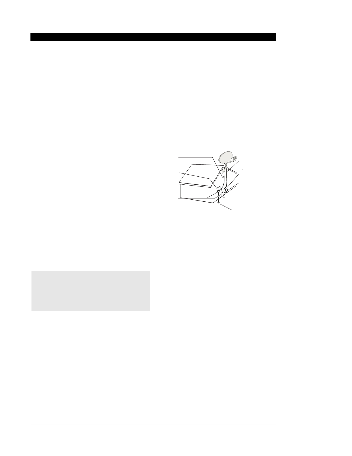
Satellite Dish Antenna Grounding—The outdoor
satellite dish antenna used to receive satellite signals and
the cable used to connect the satellite dish antenna to the
indoor receiving unit are required to comply with local
installation codes and the appropriate sections of the
National Electric Code (NEC) and in particular Article
810–15, which covers proper installation and grounding
of television receiving equipment, as well as to Article
820–33, which specifies that the satellite dish antenna
cable ground shall be connected to the grounding system
of the building as close to the point of cable entry as
practical. These codes require proper grounding of the
metal structure of the outdoor satellite dish antenna and
grounding of the connecting cable at a point where it
enters the house (or other building). If you are having a
professional installer make the installation, the installer
must observe installation codes. This manual contains
instructions on how to make the installation in
compliance with the NEC. If additional local installation
codes apply, contact local inspection authorities.
Ground
clamp
Electric
service
equipment
Ground
clamps
Coaxial cable
Grounding block
Coaxial cable
Grounding
conductor
Power service
grounding electrode
EXAMPLE OF ANTENNA GROUNDING
ACCORDING TO THE NATIONAL ELECTRICAL
CODE INSTRUCTIONS CONTAINED IN “RADIO
AND TELEVISION EQUIPMENT”
Note: The HD receiver shall be grounded through the
satellite/local antenna cable before plugging into the
telephone jack, and it must remain grounded thereafter.
Water and Moisture—Warning! To reduce the risk of
fire or electric shock, do not expose this apparatus to rain
or moisture.
Lightning—For added protection for this product,
unplug this apparatus during lightning storms or when
unused for long periods of time. Unplug it from the wall
outlet, disconnect the antenna and cable system, and
disconnect it from the telephone line. This will prevent
damage to the product due to lightning and power line
surges.
Television Antenna Information—Installing an
outdoor antenna can be hazardous and should be left to a
professional antenna installer. Do not locate the outside
antenna system in the vicinity of overhead power lines or
other electric light or power circuits or where it can fall
into such power lines or circuits. When installing an
outside antenna system, take extreme care to keep from
touching such power lines or circuits, as contact with
them might be fatal. If an outside antenna is connected to
the HD receiver, be sure the antenna system is grounded
so as to provide some protection against voltage surges
and built-up static charges. Section 810 of the NEC,
Page iv
Page 5

Installation
NFPA No. 70 1987, provides information with respect to
proper grounding of the mast and supporting structure,
grounding of the lead-in wire to an antenna discharge
unit, size of the grounding conductors, location of
antenna discharge unit, connection to grounding
electrodes, and requirements for the grounding electrode.
Note to CATV System Installer—This reminder is
provided to call the CATV system installer’s attention to
Section 820-40 of the NEC which provides guidelines for
proper grounding and particularly specifies that the cable
ground shall be connected to the grounding system of the
building, as close to the point of cable entry as practical.
Power Lines—Extreme care must be taken when
installing and adjusting or maintaining the outdoor
antenna and connecting cable, especially in the vicinity of
overhead power lines, electric lights, or power circuits.
When installing the outdoor antenna or cable, extreme
SERVICE
Servicing—Do not attempt to service this HD receiver
yourself as opening or removing covers may expose you
to dangerous voltage or other hazards. There are no user
serviceable parts inside. Refer all servicing to qualified
service personnel.
Conditions Requiring Service—Unplug the HD
receiver from the wall outlet and refer servicing to
qualified personnel under the following conditions:
● When the power supply cord or plug is damaged.
● If liquid has been spilled on, or objects have fallen
into, the HD receiver or it has been exposed to water.
● If the HD receiver does not operate normally by fol-
lowing the operating instructions. Adjust only those
controls that are covered by the operating instructions.
Other adjustments may result in damage and will
care should be taken to keep from touching or
approaching such power lines or circuits, as contact with
them might be fatal.
Cleaning—Unplug this HD receiver from the wall outlet
before cleaning. Do not use liquid cleaners or aerosol
cleaners. Clean only with dry cloth.
Object and Liquid Entry—Never push objects of any
kind into this HD receiver through openings as they may
touch dangerous voltages or short out parts that could
result in a fire or electric shock. Never spill liquid of any
kind on the HD receiver. No objects filled with liquids,
such as vases, shall be placed on the apparatus.
often require extensive work by a qualified technician
to restore the HD receiver to its normal operation.
● If the HD receiver has been dropped or the cabinet has
been damaged.
● When the HD receiver exhibits a distinct change in
performance.
Replacement Parts—When replacement parts are
required, have the technician verify that the replacements
being used have the same safety characteristics as the
original parts. Use of replacement parts specified by the
manufacturer can prevent fire, electric shock, or other
hazards.
Safety Check—Upon completion of any service or
repairs to this HD receiver, ask the service technician to
perform safety checks recommended by the manufacturer
to determine that the HD receiver is in safe operating
condition.
Page v
Page 6

Hughes Model HIRD-E86 Platinum HD Receiver
Federal Communications Commission
(FCC) Regulatory Information
Federal Communications Commission (FCC)—
This equipment complies with both Part 15 and Part 68 of
the FCC rules.
Part 15 compliance—
This equipment has been tested and found to comply with
the limits for a Class B digital device, pursuant to Part 15
of the FCC rules. These limits are designed to provide
reasonable protection against harmful interference in a
residential installation. This equipment generates, uses
and can radiate radio frequency energy and, if not
installed and used in accordance with the instructions,
may cause harmful interference to radio communications.
However, there is no guarantee that interference will not
occur in a particular installation. If this equipment does
cause harmful interference to radio or television
reception, which can be determined by removing and
applying power to the equipment, the user is encouraged
to try to correct the interference by one or more of the
following measures:
● Reorient or relocate the receiving satellite dish
antenna.
● Increase the separation between the equipment and the
HD receiver.
● Connect the equipment into an outlet on a circuit dif-
ferent from that to which the HD receiver is connected.
● Consult the dealer or an experienced radio/TV techni-
cian for help.
The user may find the following booklet, prepared by the
Federal Communications Commission, helpful: “How to
Identify and Resolve Radio and TV Interference
Problems.” This booklet is available from the U.S.
Government Printing Office, Washington, DC.
To meet FCC requirements, only peripherals (computer
input/output devices, terminals, printers, etc.) certified to
comply with the Class B limits may be attached to this
device. Operation with noncertified peripherals is likely
to result in interference to radio and TV reception.
To meet FCC requirements, shielded cables are required
to connect the device to a personal computer, peripheral,
or other Class B certified device.
Part 68 compliance—
1) This equipment complies with Part 68 of the FCC
rules. On the modem card is a label that contains,
among other information, the FCC Registration
Number and Ringer Equivalence Number (REN) for
this equipment. If requested, this information must
be provided to the Telephone Company.
The REN is used to determine the quantity of
devices which may be connected to the telephone
line. An excessive number of REN’s on the line may
result in the devices not ringing in response to an
incoming call. In most, but not all areas, the sum of
the number of REN’s should not exceed five (5). To
be certain of the number of devices that may be
connected to the line, contact the Telephone
Company to determine the maximum number of
REN’s permitted for the calling area.
2) If the terminal equipment Platinum (Model Number:
HIRD-E8) causes harm to the telephone network,
the Telephone Company will notify you in advance
that temporary discontinuance of service may be
required. But, if advance notice is not practical, the
Telephone Company will notify you as soon as
possible. Also, you will be advised of your right to
file a complaint with the FCC, if you believe it is
necessary.
3) The Telephone Company may make changes in its
facilities, equipment, operations, or procedures that
could affect the operation of the equipment. If this
happens, the Telephone Company will provide
advance notice in order for you to make the necessary modifications in order to maintain interrupted
service.
4) If trouble is experienced with the equipment Platinum HD Receiver (Model Number: HIRD-E8),
please contact the following for repair and/or warranty information:
Hughes Customer Care Center
Germantown, MD 20876
Telephone Number: 1-800-274-8995
http://www.hns-usa.com
email: hughestv@hns.com
● Hughes Network Systems must make any neces-
sary repairs to the modem portion of this equipment in order to maintain valid FCC registration.
Do not attempt to repair or service your modem.
Return it to Hughes Network Systems.
● No repairs can be made by customers. All repairs
are to be done by Hughes Network Systems
Authorized Service Centers (ASC).
● This equipment cannot be used on public coin
service provided by the Telephone Company.
Connection to Party Line Service is subject to
state tariffs.
Page vi
Page 7

Table of Contents
Important Safety Instructions............................iii
Federal Communications Commission (FCC)
Regulatory Information............................vi
A First Look at the HD System........................1-1
What You Should Do First.........................1-1
How Does All This Work? .........................1-2
HD System Components ................................1-3
The DIRECTV PLUS™ Satellite Dish
Antenna.................................................1-3
The HD Receiver with DIRECTV PLUS™
Receiver Built-in ...................................1-4
The Remote Control...................................1-6
Installing the Remote Control Batteries ....1-8
Setting Up Your HD Receiver..........................2-1
Choosing the Best Connection for Your
Entertainment System...........................2-2
HD Receiver and Satellite Dish
Antenna with Terrestrial Antenna
or Cable Service ...................................2-3
HD Receiver and HDTV Monitor..............2-4
HD Receiver with HDTV Monitor and
VCR.......................................................2-5
HD Receiver and Standard Definition
TV Monitor ...........................................2-8
HD Receiver with Standard Definition
TV Monitor and VCR ............................2-9
HD Receiver and Dolby
Receiver or Decoder...........................2-12
HD Receiver and Standard Stereo
System .................................................2-13
Finishing Up............................................2-13
Connecting the VCR Control Cable.............2-14
Finding the VCR’s Remote Control
Sensor .................................................2-14
RF Remote Control Receiver .......................2-14
Connecting the RF Remote Control
Receiver/Antenna ...............................2-15
Setting the Address of Your HD
Receiver and Remote Control.............2-15
Now You Can Turn It On.............................2-15
POWER-ON Screen.................................2-16
Exit...........................................................2-16
Installation...............................................2-16
Controlling the HD Receiver............................3-1
Front Panel vs. Remote Control Keys............3-1
Basic Navigation ............................................3-1
®
Digital
Setting Up the Satellite Dish Antenna and
Terrestrial Inputs.................................... 4-1
Installing and Testing the Satellite Dish
Antenna ................................................ 4-1
Displaying the INSTALLATION Screen...... 4-2
Selecting the Correct Type of Satellite
Dish Antenna........................................ 4-2
Dish Type Selections................................. 4-2
Finding the Correct Antenna-pointing
Coordinates .......................................... 4-3
Pointing the Dish Antenna........................ 4-4
Testing Signal Strength ............................. 4-4
Local Providers......................................... 4-4
Local Provider Area Options.................... 4-5
System Test................................................ 4-5
Fine Tuning the Pointing of the Dish
Antenna ................................................ 4-6
Selecting Transponders............................. 4-6
Adding Terrestrial Antenna or Cable
to Your Satellite Connections .............. 4-7
Local In Connection Options .................... 4-7
Clear ......................................................... 4-8
Scan Channels........................................... 4-8
Testing the Strength of the Terrestrial
Digital Channels .................................. 4-8
Terrestrial Antenna or Cable without
a Satellite Connection .......................... 4-9
Local In Connection Options .................... 4-9
Scan Channels......................................... 4-10
Selecting the Correct Satellite Dish
Type for Terrestrial-only
Operation ........................................... 4-10
Editing Local Channels .......................... 4-10
Time Setup................................................... 4-10
Installation Is Now Complete...................... 4-10
Watching Local Terrestrial and DIRECTV
Programming .......................................... 5-1
Types of Channels ......................................... 5-1
Analog (NTSC) Channels without Dish
Connection ........................................... 5-1
Analog (NTSC) Channels with Dish
Connection ........................................... 5-1
Digital (ATSC) Channels without Dish
Connection ........................................... 5-1
Digital (ATSC) Channels with Dish
Connection ........................................... 5-1
Local Channels from DIRECTV ............... 5-2
DIRECTV
®
Programming ........................ 5-2
®
Page vii
Page 8

Hughes Model HIRD-E86 Platinum HD Receiver
Basic Channel Changing ............................... 5-2
Channel Banner........................................ 5-2
The Information Banner ........................... 5-3
The OneLine™ Guide............................... 5-3
TurboTune™............................................. 5-3
AlphaTune................................................. 5-3
Alternate Services.......................................... 5-4
Audio......................................................... 5-4
Closed Caption ......................................... 5-4
Advanced Program Guide™ ........................... 6-1
Program Guide............................................... 6-1
PROGRAM GUIDE Screen ...................... 6-1
PROGRAM GUIDE Pop-up Menu ........... 6-2
Choosing the Guide Style.......................... 6-2
Descriptions.............................................. 6-5
Filtering the Guides ....................................... 6-5
Theme Filters ............................................ 6-6
Channel List.............................................. 6-6
Guide Times .............................................. 6-7
WATCHWORD™ ........................................ 6-7
WATCHWORD™ Entry ........................... 6-7
General On-Screen Guide Features ......... 6-7
The INFORMATION Screen........................ 6-8
Done.......................................................... 6-8
Show Times............................................... 6-8
SHOW TIMES Screen ............................... 6-8
Done.......................................................... 6-9
Video ......................................................... 6-9
Guides ....................................................... 6-9
PreSelect™ ............................................... 6-9
PreSelecting Programs from the
Advanced Program Guide™................ 6-9
PreSelecting Programs for Viewing ....... 6-10
Canceling PreSelected Programs........... 6-10
HD Receiver’s Menu System........................... 7-1
Menu Overview......................................... 7-1
Main Menu .................................................... 7-2
Guide......................................................... 7-2
Video ......................................................... 7-2
Setup Menu.................................................... 7-2
Done.......................................................... 7-2
Video ......................................................... 7-2
Preferences .................................................... 7-3
Done.......................................................... 7-3
Video ......................................................... 7-3
Advanced................................................... 7-3
Preference Options ................................... 7-3
Channel Tags ............................................ 7-3
Scheme ...................................................... 7-3
Filters ........................................................ 7-4
Translucency .............................................7-4
Advanced Preferences.................................... 7-4
Done .......................................................... 7-4
Video .........................................................7-4
Advanced Preference Options...................7-4
Receiver ID ...............................................7-4
Channel Lock ............................................ 7-5
Factory Defaults ....................................... 7-5
Audio/Video Setup ........................................ 7-5
Audio .........................................................7-5
Dolby Digital............................................. 7-5
Closed Caption..........................................7-6
TV Resolution............................................ 7-6
Screen Ratio ..............................................7-6
Image Shape .............................................. 7-6
Limits ............................................................. 7-7
Done .......................................................... 7-7
Video .........................................................7-8
TV Timer ................................................... 7-8
Rating Help ............................................... 7-8
Max Spending............................................ 7-9
Channel Lists ...............................................7-10
Done ........................................................ 7-10
Video .......................................................7-10
AutoSet ....................................................7-10
Rename....................................................7-10
Clear........................................................ 7-11
Set............................................................7-11
Tag Boxes................................................ 7-11
TurboTune™................................................7-11
Done ........................................................ 7-11
Video .......................................................7-11
Set Channel .............................................7-12
Installation ...................................................7-12
VCR Setup ...................................................7-12
Brand....................................................... 7-12
Code ........................................................7-12
Test (Record/Stop)...................................7-12
Scheduler .....................................................7-13
Done ........................................................ 7-13
Video .......................................................7-13
Event Scheduling Options ....................... 7-13
Editing an Event......................................7-13
Check Mail................................................... 7-14
Message...................................................7-14
Page ........................................................7-15
Erase ....................................................... 7-15
Page viii
Page 9

Table of Contents
Purchases......................................................7-15
Done ........................................................7-15
Video........................................................7-15
History .....................................................7-15
Upcoming Purchases...............................7-15
Buy...........................................................7-16
Buy Options .............................................7-16
Cancel Purchase......................................7-16
Purchase History .....................................7-16
Caller ID.......................................................7-17
Call History .............................................7-17
Done ........................................................7-17
Video........................................................7-17
Disable.....................................................7-17
Call History .............................................7-17
Help .........................................................7-17
Lock/Unlock.................................................7-18
Locking Procedure ..................................7-18
Unlocking Procedure...............................7-18
Temporarily Overriding the Lock............7-19
Programming Your Remote Control.............. 8-1
Programming the Remote Control................. 8-1
Programming Mode.................................. 8-1
Code Scan ................................................. 8-1
Code Entry ................................................ 8-2
Using the Remote Control............................. 8-5
Changing the Remote Control
Address to Operate Other HD
Receivers .............................................. 8-5
Identifying Codes That Have
Been Stored .......................................... 8-5
Controlling Other Components Using
the AUX Button .................................... 8-6
Questions and Answers ................................... A-1
Page ix
Page 10

Page 11

A First Look at the
HD System
1
Congratulations! You’ve selected one of the most advanced digital video and audio components
available today. You now have the capacity to receive hundreds of channels of video
programming and digital-quality audio.
What You Should Do First
Your HD system is both a sophisticated technical product and an easy-to-operate source of
entertainment. You should complete the following steps to achieve the greatest performance from
your system:
● Read this manual to familiarize yourself with the system.
● Install the HD receiver.
● Connect the terrestrial antenna or cable for local analog and digital channels.
● Install the DIRECTV PLUS™ antenna and cables. Professional installation is strongly
recommended.
● Align the satellite dish antenna.
● Arrange for programming from DIRECTV.
Page 1-1
Page 12
Hughes Model HIRD-E86 Platinum HD Receiver
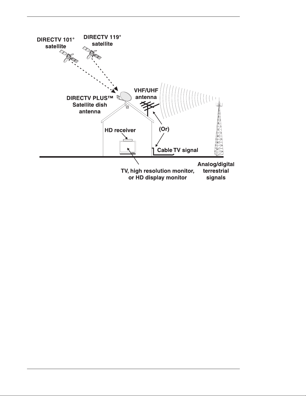
The Broadcasting and Receiving network
How Does All This Work?
First, here is some information about your HD receiver. Your HD receiver can receive three types
of television signals:
● Analog signals in NTSC (National Television Systems Committee—traditional TV sig-
nals) format—from terrestrial, or broadcasting towers built on earth, and cable sources.
● Digital signals in ATS C (Advanced Television Systems Committee—digital TV signals)
format—from terrestrial sources.
● Digital Satellite signals—from DIRECTV satellites in space. These signals can be either
Standard Definition (SD) signals or High Definition (HD) signals.
Second, here is some information about the broadcasting and receiving network shown.
Television stations, film studios, and other broadcasters send signals to earthbound terrestrial
broadcasting towers and satellites. The tower shown on the right is sending Digital ATSC format
signals and the more traditional Analog NTSC format signals. Both ATSC and NTSC signals can
be received by the same VHF/UHF antenna normally mounted on a roof or in an attic. The
satellites shown are sending DIRECTV programming signals which are received by a DIRECTV
PLUS™ Satellite Dish Antenna usually mounted on a roof or on the ground. These satellites are
located in geostationary orbit. Cable television signals are received through cables installed by
cable television providers. The terrestrial broadcast (from a tower), satellite, and cable signals
then go into your HD receiver where they are processed and sent to your television set.
Page 1-2
Page 13
A First Look at the HD System
HD System Components
There are three main components of the HD system. They are the DIRECTV PLUS™ satellite
dish antenna, the HD receiver, and the remote control.
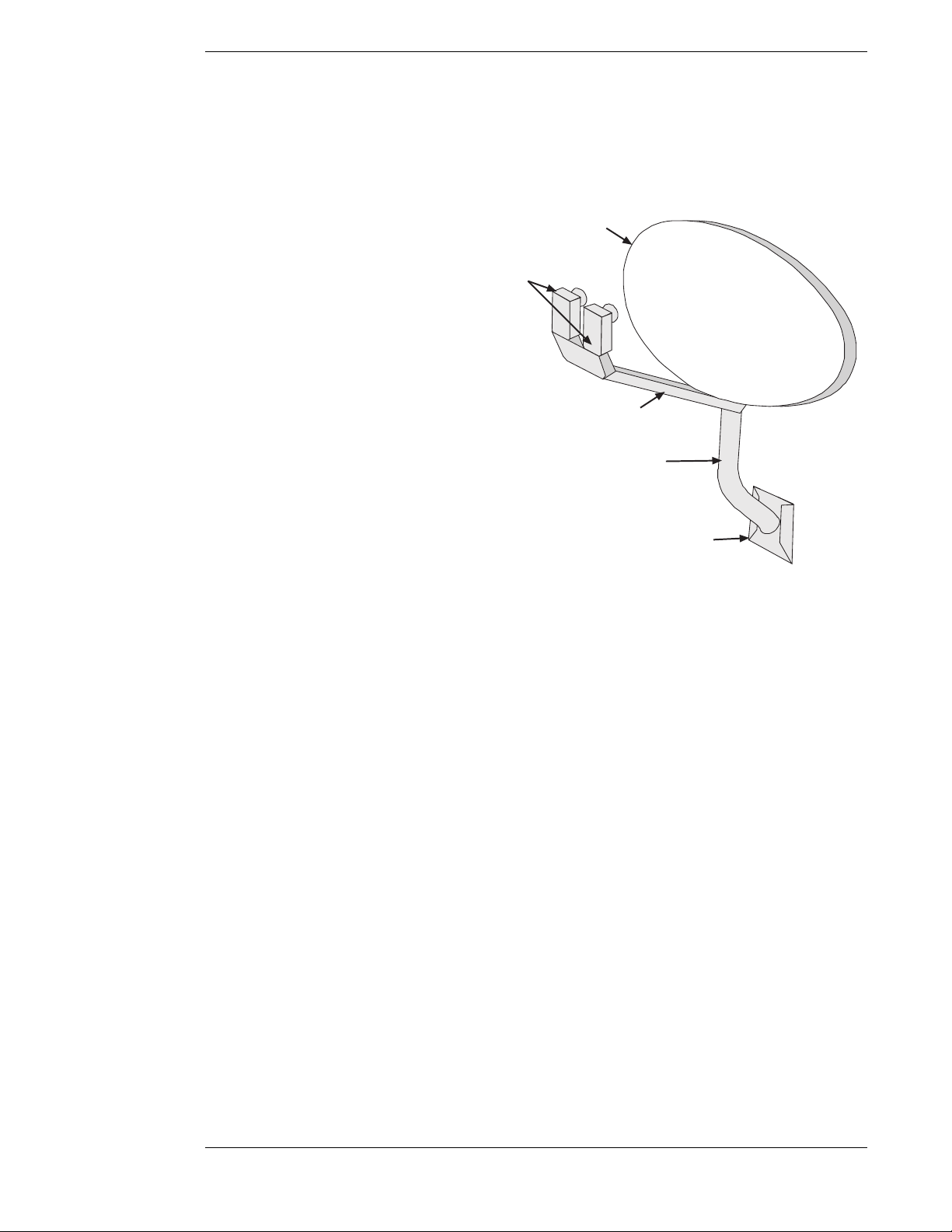
The DIRECTV PLUS™ Satellite Dish Antenna
The satellite dish antenna is the
component that receives the digital
signals. It must be mounted to a solid
outdoor surface that allows a clear view
of the southern sky.
The large dish-shaped part is known as
the reflector. The oval-shaped DIRECTV
PLUS™ satellite dish antenna enables
reception of DIRECTV High Definition
Programming throughout the United
States and local stations in specific cities.
The dimenstions of the oval dish reflector
are approximately 18 inches high by 24
inches wide.
Reflector
LNBs
LNB support arm
Mast
A Low Noise Block (LNB) Down
Converter assembly is attached to the
Base plate
satellite dish antenna at the end of a
tubular arm. Your assembly provides for
receiving signals from multiple satellite
orbit locations and distributing the signal
The satellite dish antenna parts. While your dish may vary
in appearance, the components are referred to using the
same names.
to the HD receiver and up to 3 more DIRECTV digital satellite receivers through the use of a
multiswitch (not shown).
The mounting bracket and base plate make adjustments easy during installation. Once the
satellite dish antenna has been properly positioned to point toward the satellites, you should never
need to adjust it again.
Refer to the instructions included with the satellite dish for more details. Professional installation
is strongly recommended.
Page 1-3
Page 14
Hughes Model HIRD-E86 Platinum HD Receiver
▲
▲
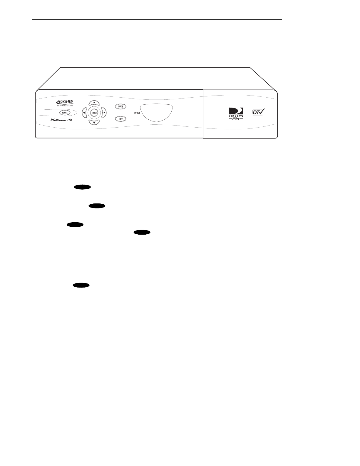
The HD Receiver with DIRECTV PLUS™ Receiver Built-in
The HD receiver is one of the most compact available today. The basic features for setup,
installation, and viewing programming can be accessed from the front panel keys.
The front of the HD receiver
Your access card is located behind the door on the right side of the HD receiver. This special card
contains information about your services. This card should not be removed except to protect the
HD receiver from unauthorized use or to replace the card when DIRECTV supplies a new one.
The power key ( ) is used to turn the HD receiver on and off. The power light will
POWER
illuminate when the unit is on.
The information key ( ) is used to display descriptions of programs and channels on your
INFO
TV screen.
Pressing the ( ) key on the front panel will display the on-screen guide, where you can see a
listing of all available programs. If the ( ) key is pressed while the program guide is already
GUIDE
GUIDE
displayed, the Guide Pop-Up menu will be displayed. The Guide Pop-Up menu provides access
to the Main Menu or to the different program guide sorting options.
The four directional keys, up ( ), down ( ), left ( ), and right ( ), are used to move the highlight
▲
▲
around the program guide and menus. Up and down keys also provide access to the OneLine™
Guide when menus aren’t displayed.
The select key ( ) is used to access a highlighted guide or menu item.
SELECT
Page 1-4
Page 15
A First Look at the HD System
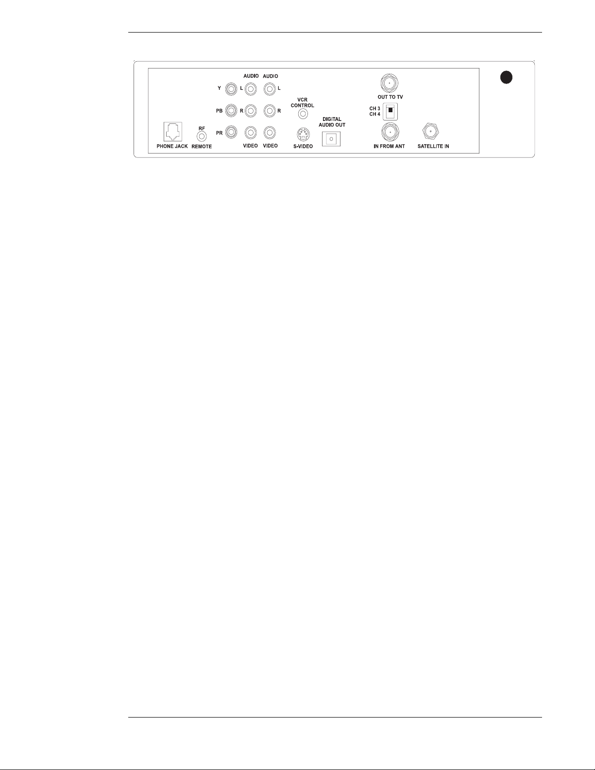
The rear of the HD receiver (power cord not shown)
The rear of the HD receiver has numerous jacks for connection to your audio/video entertainment
system. You will also find the power cord permanently connected to the back.
The SATELLITE-IN F-type jack is for connecting the cable from your satellite dish antenna to the
HD receiver. Be sure that you use RG-6 cable only. The SATELLITE-IN F-type jack can also accept
a terrestrial analog or digital input when combined with the satellite signal using a diplexer.
Note: Refer to “HD Receiver and Satellite Dish Antenna with Terrestrial Antenna or Cable
Service” in Chapter 2 for more information on using a diplexer. This is an advanced
installation technique and professional installation is recommended.
The IN FROM ANT jack is for connecting a terrestrial analog or digital antenna to your HD
receiver.
The OUT TO TV F-type jack is an RF output that you may connect to your standard definition
(SD) TV or videocassette recorder (VCR) (depending on your entertainment system). Note that
the CH3/CH4 switch enables you to select the channel on which HD receiver signals will appear.
Select this channel on your TV or VCR to view or record these signals.
Three component signal output jacks Y (Luminance), P
from Luminance), and P
(the amount of color Blue is different from Luminance) are connected
b
(the amount of color Red is different
r
to a High Definition (HD) monitor set to achieve highest quality video images. The output format
is always 1080i.
The phono-type AUDIO output jacks, labeled and color-coded (L is white, and R is red) to indicate
Left and Right, can be used for connection to your TV, VCR, or audio system. The phono-type
composite VIDEO output jack is color-coded yellow and provides SD video signals. You may use
this jack for connection to your TV or VCR. The multiple-pin S-VIDEO jack is for high-quality
video output. Use this jack to achieve the clearest SD picture for your TV or VCR. The output
format signals for RF, video, and S-video are always 480i.
The VCR CONTROL mini-jack is for connecting the VCR control cable that is included with
the system. With this cable, the HD receiver can interface with most popular brands of VCRs to
record selected programs automatically.
There is one DIGITAL AUDIO OUT connector which is OPTICAL. It provides signals for
®
connection to a Dolby
Digital decoder.
The RF REMOTE jack is used to plug in the RF receiver which came with your system.
Connecting this receiver will allow you to operate the HD receiver from other rooms in your
home when using the Whole House RF remote control.
The standard RJ-11 modular PHONE JACK is for connecting the HD receiver to your telephone
line. This telephone connection is necessary to access certain program offerings such as Pay Per
View. Telephone calls generated by the HD receiver are toll-free. The telephone line connection
will not normally interfere with your telephone operation.
Page 1-5
Page 16
Hughes Model HIRD-E86 Platinum HD Receiver
POWER
▲
▲
Note: The HD receiver will convert all video signals to High Definition (1080i
format) and send these through the Y, P
, and Pb connectors. Also the HD
r
receiver will convert all video signals to Standard Definition (480i format) and
send these through the OUT TO TV, VIDEO, and S-VIDEO connectors.
When Standard Definition is being sent, the Y, P
send any video. The HD receiver cannot send both HD and SD at the same
time.
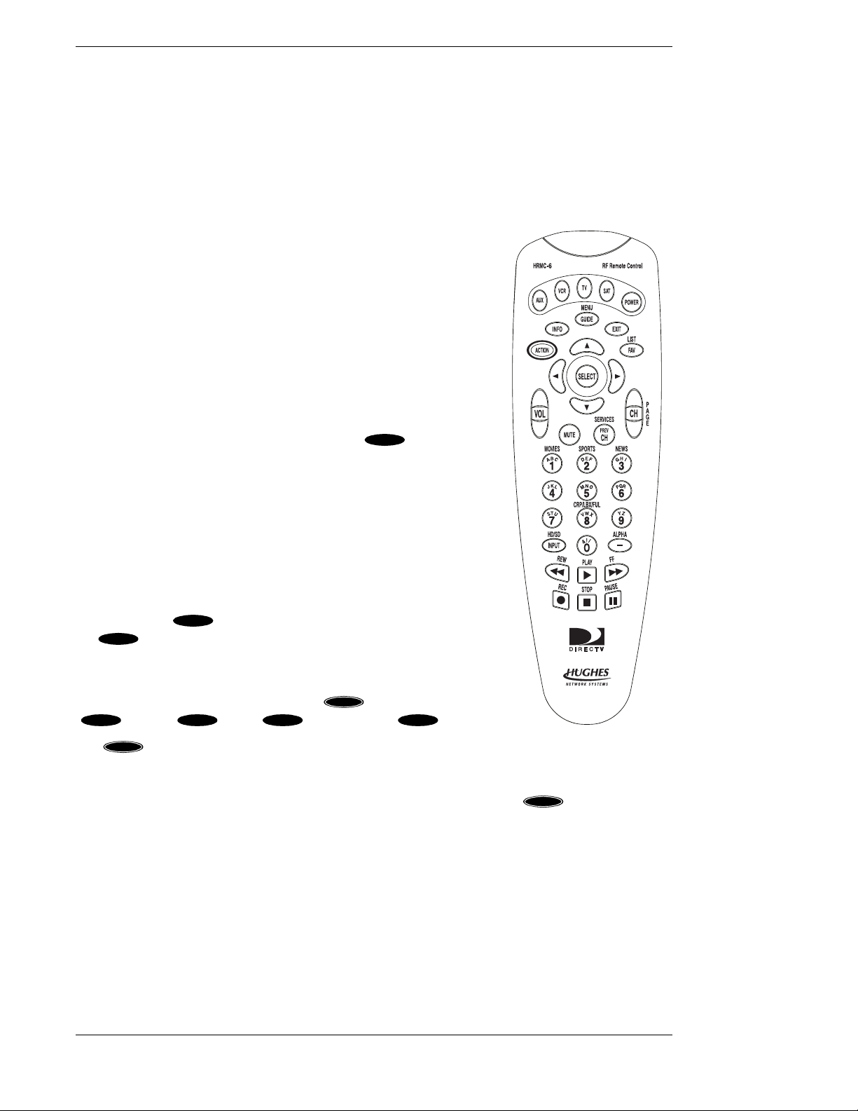
The Remote Control
Your HD receiver includes an RF/IR remote control and RF
receiver. With this combination you can have complete control of
your HD receiver anywhere in your house. Refer to “RF Remote
Control Receiver” for instructions on setting up the RF receiver.
Each remote control can control your HD receiver and most TV
brands, as well as VCRs and many other auxiliary devices such as
cable boxes, amplifiers, and laser disc players.
The mode keys across the top of the remote control enable you to
specify the device you intend to control. This is important since
many devices share the same keys, such as the key and the
numeric keys. You must press the appropriate device key before
pressing a command key to make sure the remote control sends
the right signal to the right device. The only keys that deviate
from this rule are the blue keys, as they are always associated with
the HD receiver.
, and Pb connectors will not
r
For the HD receiver only, the four directional keys will cause the
on-screen highlight to move in the direction you want. The keys
will be referred to as , , , and .
The select key ( ) is one of the most important keys. Pressing
SELECT
the key will tell the HD receiver that you wish to choose the
SELECT
▲
▲
highlighted item.
The arch of keys above the directional keys control frequently used
functions. These include special action ( ), information
INFO GUIDE EXIT FAV
( ), guide ( ), exit ( ), and favorite ( ) keys.
ACTI ON
The key is unique because it does nothing by itself. Pressing
ACTI ON
The remote control
it displays the action icon in the upper left corner of your screen for
a few seconds. During that time, other keys may be pressed to access special functions indicated
in yellow above the keys. Refer to the chart on the next page for a list of key functions.
ACTI ON
Page 1-6
Page 17
A First Look at the HD System
SAT
▲
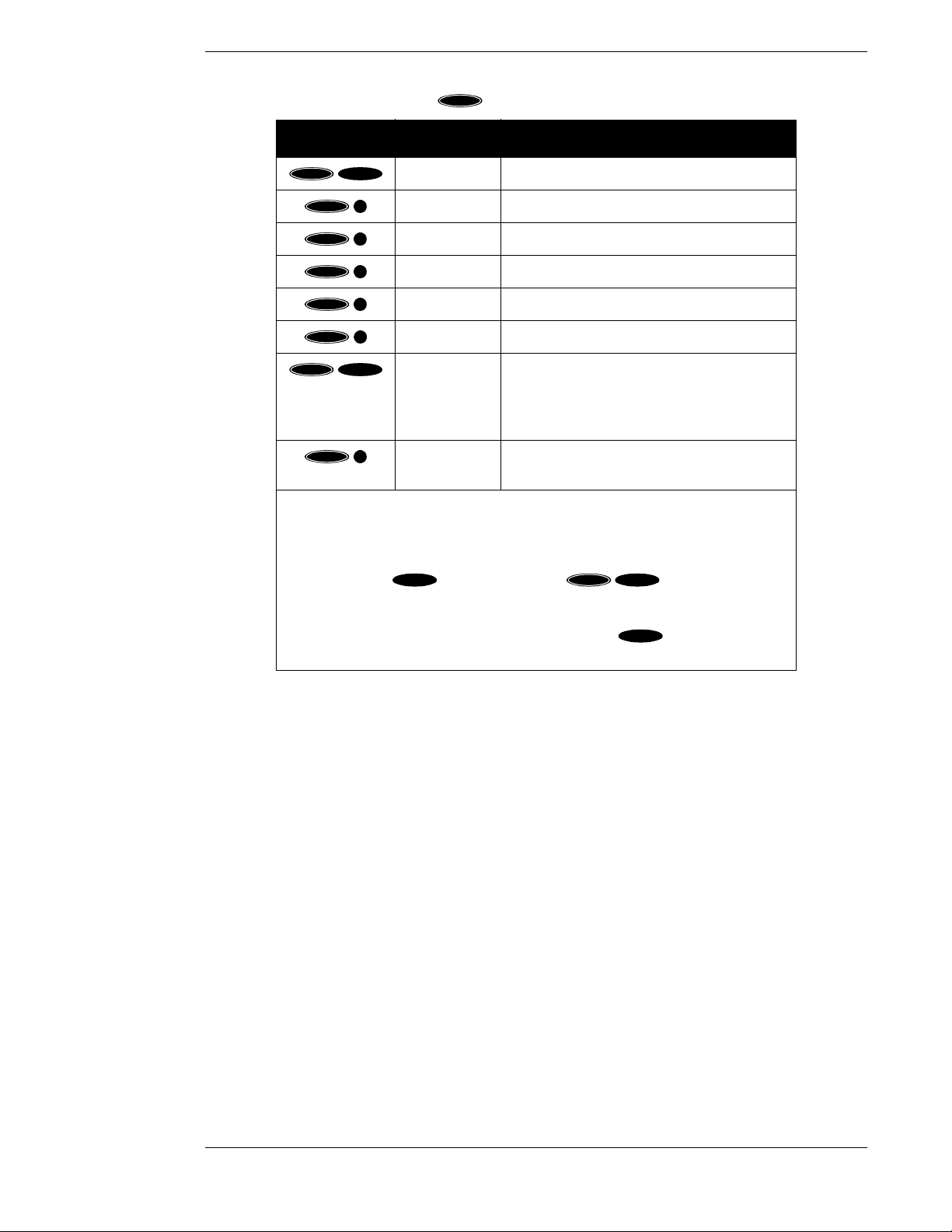
The following chart describes the key functions for easy reference:
ACTI ON
Keys Label Feature
ACTI ON
ACTI ON
ACTI ON
ACTI ON
ACTI ON
ACTI ON
ACTI ON
FAV
PREV
CH
1
2
3
–
INPUT
LIST Displays the CHANNEL LISTS screen
SERVICES Displays the Alternate Services menu
MOVIES Filters the on-screen guide to movies only*
SPORTS Filters the on-screen guide to sports only*
NEWS Filters the on-screen guide to news only*
ALPHA Select channel by call sign
HD/SD Switches the output of the HD receiver
between HD and SD** Also switches
between the DTV (HD) input and INPUT 2
(SD) on Mitsubishi HD-upgradeable TVs.
ACTI ON
8
Changes display between FULL, CROPPED
and LETTERBOX or SIDE PANELS.
* Pressing this sequence a second time will undo the respective filter.
** HD formatted video output (1080i) uses the Y, P
, and Pb jacks. SD formatted
r
video output (480i) uses the Video, S-video, and Out to TV jack. Note: The first
time you turn your system on, the HD formatted video output is active. You may
have to press the key followed by the key sequence twice
ACTI ON
INPUT
to get any picture. A complete explanation of switching from HD to SD can be
found in the section “Now You Can Turn It On” on page 2–15. You can
also achieve this from the front panel by pressing the and keys
GUIDE
simultaneously.
The remaining keys are HD receiver-specific keys and common device keys, including numbers,
channel up and down, etc. The functions of these keys change depending on the device currently
selected.
Please refer to “Controlling the HD Receiver” in Chapter 3 for more remote control capabilities
and “Programming Your Remote Control” in Chapter 8 for setting your remote control to handle
other audio/video components.
Descriptions and details of each individual key will be given in the appropriate subsections
throughout this manual.
Page 1-7
Page 18
Hughes Model HIRD-E86 Platinum HD Receiver
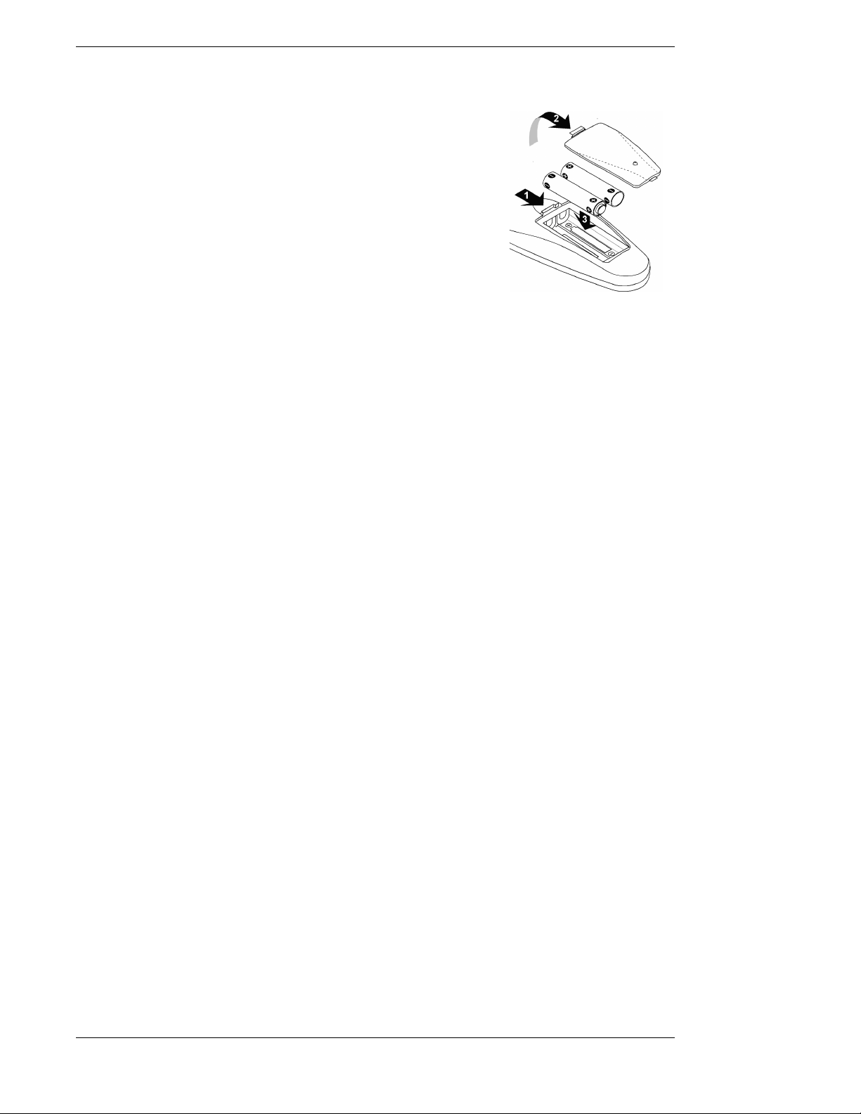
Installing the Remote Control Batteries
Before the remote control can be used, the two supplied batteries
need to be installed. First, unsnap the battery cover from the back
of the remote control. Install each fresh battery as shown, making
sure that the + and – on each battery line up with the marks in the
battery compartment. Next, snap the cover back onto the remote
control.
Refer to “Programming Your Remote Control” in Chapter 8 for
setting the codes to control the devices in your entertainment
system.
Battery installation
Page 1-8
Page 19
Setting Up Your
HD Receiver
2
It is recommended that you have the satellite dish antenna professionally installed due to safety
issues and electrical codes.
Note: If you should choose to install the dish antenna yourself, please pay
special attention to the precautions in the front of this manual and refer to the
installation instructions packaged with the satellite dish antenna. You can find
information on using this HD receiver to point the dish antenna in Chapter 4,
“Setting Up the Satellite Dish Antenna and Terrestrial Inputs.”
DANGER
To reduce the risk of fire or
electrical shock, do not
expose this apparatus to rain
or moisture.
You may also want to obtain the Do-It-Yourself Installation Kit, sold separately.
This chapter provides step-by-step instructions for setting up your HD system and connecting it
to your television or entertainment system.
The carton includes the HD receiver with DIRECTV PLUS™ receiver built-in, an access card
(already installed in the HD receiver behind the door), an RF/IR remote control (batteries
included), RF remote control receiver, cables, and the Owner’s Manual.
You now need to decide where you want to place the HD receiver. Choose a location near your
TV where the power cord or cables will not be inadvertently disconnected.
CAUTION
Do not stack electronic components or other objects on
top of the HD receiver. The
slots on top of the receiver
must be left uncovered to
allow proper airflow to the unit. Blocking the
airflow to the unit could impair performance
or damage your receiver. Also do not stack
the HD receiver on top of a “hot” component such as an audio power amplifier.
Page 2-1
Page 20

Hughes Model HIRD-E86 Platinum HD Receiver
Choosing the Best Connection for Your
Entertainment System
There are a number of ways to connect the HD receiver, depending on the other audio/video
equipment you wish to use. The simplest hookups are described in the following
subsections.
The rear of the HD receiver (power cord not shown)
Before connecting the HD receiver to your entertainment system, you
should connect the phone line. This can be done by plugging one end of the
provided telephone cable into the PHONE JACK on the back of the HD
receiver and the other end into a telephone wall jack. If you do not have a
telephone jack within reach, you should move the HD receiver to be within
The phone line
and jack
reach of a telephone wall jack or have a new one installed.
To suit your specific needs, you may need to purchase additional connectors and/or cables from
your dealer or electronic hardware store. Choose which hookup method to use based on:
● The capabilities of your TV and VCR.
● Your desire to receive local terrestrial analog and/or digital programming through the HD
receiver.
● Any other devices you want to include in the system (stereo, second VCR, etc.).
Before attempting to connect anything, position yourself so you are looking at the back of your
components. Note the various input and output receptacles, their shapes, and how they are
labeled. Then read through the rest of this connection subsection before going ahead with the
actual hookup.
Note: For your safety, make sure the HD receiver, TV, VCR, and any other
devices to be connected are unplugged from the power outlet while hooking
them up.
Some of the connection methods described in this chapter may require
optional cables or accessories that are not included with your HD receiver.
Page 2-2
Page 21
Setting Up Your HD Receiver
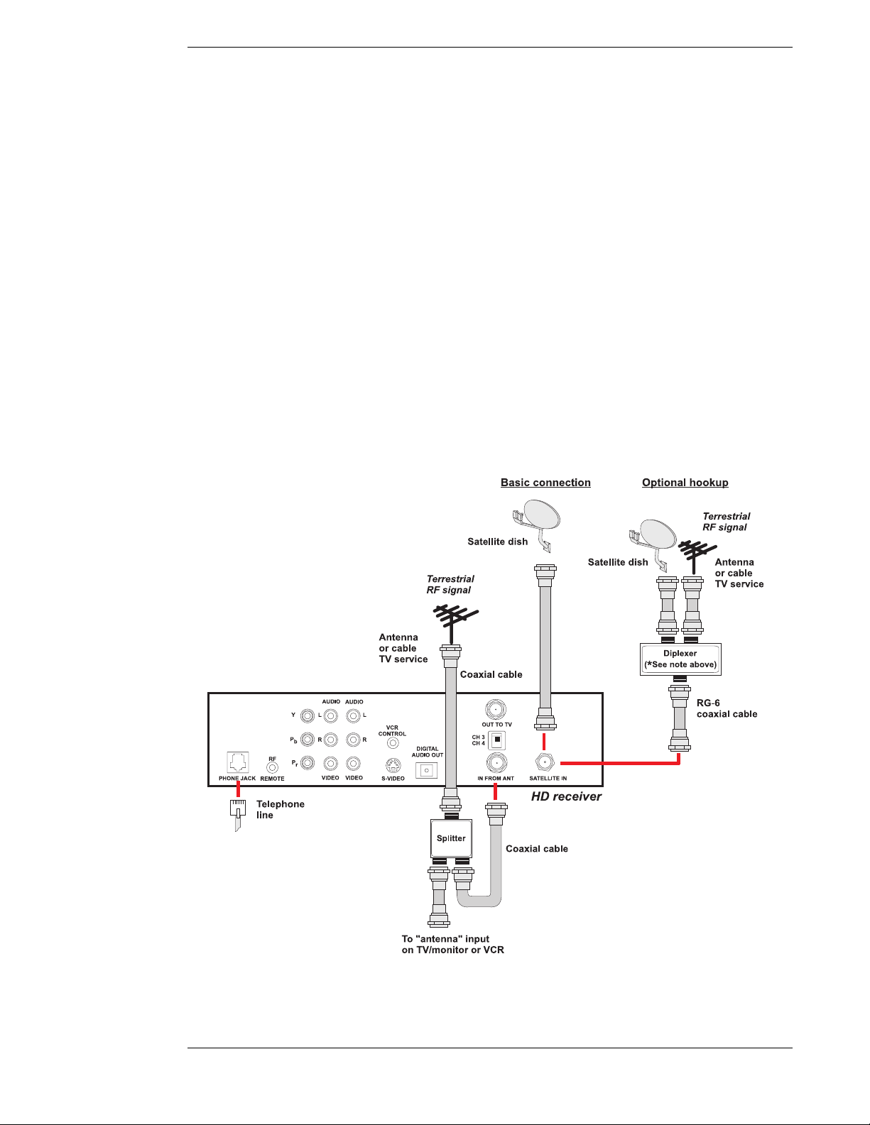
HD Receiver and Satellite Dish Antenna with Terrestrial Antenna
or Cable Service
Follow these steps indicated by the diagram below:
1) Connect the RG-6 Coaxial Cable from the satellite dish antenna to the back of the HD
receiver using the connector marked SATELLITE IN.
Optional Hookup: If you plan to combine an outside terrestrial antenna with the signal
from the satellite dish antenna, obtain a signal Diplexer* from your local retailer of
satellite accessories. Connect the RG-6 Coaxial Cable from the satellite dish antenna to
the “power pass” input of the Diplexer. Connect the output of the Diplexer to the back of
the HD receiver at the connector marked SATELLITE IN.
* Note: It is very important that you use a Diplexer that is designed to combine
satellite signals and terrestrial signals. Standard signal combiners are not
compatible.
2) Connect the cable from your terrestrial antenna or cable TV service to the HD receiver at
the connection marked IN FROM ANT.
Optional Hookup: If you plan to record a terrestrial signal while watching satellite
programming, or vice versa, connect the cable from your terrestrial antenna or cable TV
service to the input of a standard two-way splitter as shown in the hookup diagram.
Page 2-3
Page 22

Hughes Model HIRD-E86 Platinum HD Receiver
Note: In order for the Advanced Program Guide™ to receive the correct
listing of local channels and local program information from DIRECTV,
make sure you select the correct zip code, cable provider (if connecting a cable
TV service) and Area (if using a terrestrial antenna). Refer to Chapter 4,
“Setting Up the Satellite Dish Antenna and Terrestrial Inputs.”
Using both the IN FROM ANT connector and the SATELLITE connector
with a diplexer, you may connect one antenna and one cable TV service cable
at the same time, however this HD receiver and the Advanced Program
Guide™ cannot support two antennas connected or cable TV service
connected in two places at the same time.
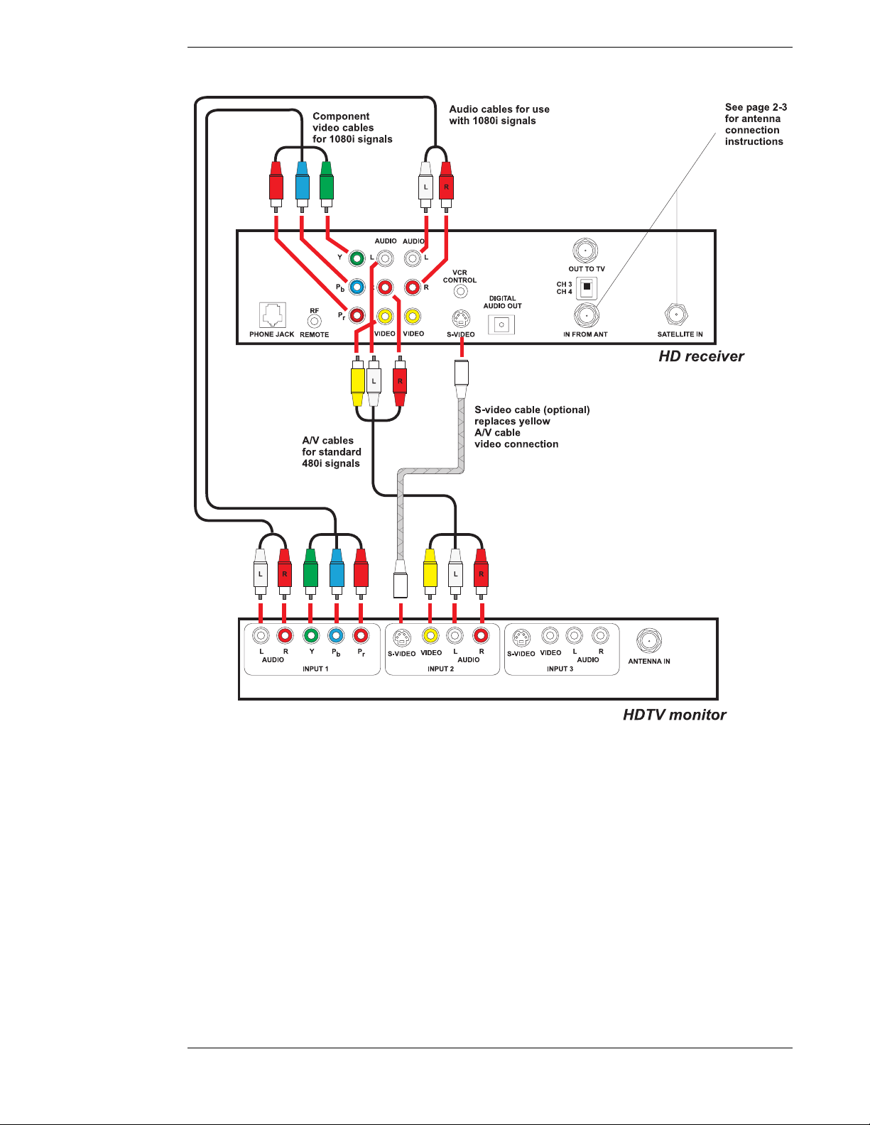
HD Receiver and HDTV Monitor
Follow these steps indicated by the diagram following this text.
1) Connect the satellite dish antenna and terrestrial antenna or cable service to the HD
receiver following instructions in “HD Receiver and Satellite Dish Antenna with Terrestrial Antenna or Cable Service” on page 2-3.
2) Connect one set of Component Video Cables (one green Y connector, one red P
tor, and one blue P
marked Y, P
r
monitor using the HDTV input connections marked Y, P
Note: Connect the Y, P
, and Pb connectors on your TV that are compatible with HD signals in the
P
r
connector) to the back of the HD receiver using the connections
b
, and Pb. Connect the other ends of this cable to the back of the HDTV
, and Pb.
r
, and Pb connectors of the HD receiver only to the Y,
r
connec-
r
1080i scanning rate and that comply with the EIA 770.3 signal standards.
Refer to your television owner’s guide for verification.
3) Connect one set of audio cables (one white left audio connector and one red right audio
connector) to the back of the HD receiver using the connectors marked AUDIO L, R.
Connect the other end of the audio cables to the back of the HDTV monitor using the
audio inputs.
Note: This connection allows the use of the speakers in the TV to hear the
sound.
4) Optional: Connect one set of audio cables and a video or S-video cable to the back of the
HD receiver using the connectors marked AUDIO L, R and VIDEO or S-VIDEO.
Connect the other end of audio and video cables to the back of the HD monitor using the
AUDIO and VIDEO or S-VIDEO inputs.
Note: This connection allows you to send standard 480i signals to your TV.
For better standard definition performance, if your TV has an S-VIDEO connector, then
use an S-video cable instead of the yellow video cable.
Page 2-4
Note: When the HD receiver is converting all signals to standard 480i signals
that can be viewed on standard video inputs of TVs, there will be no signals on
the Y, P
, and Pb connectors. When the HD receiver is converting all signals to
r
1080i that can be sent to the HDTV input of HD monitors, there will be no
standard 480i signals to standard video inputs of TVs.
Page 23
Setting Up Your HD Receiver
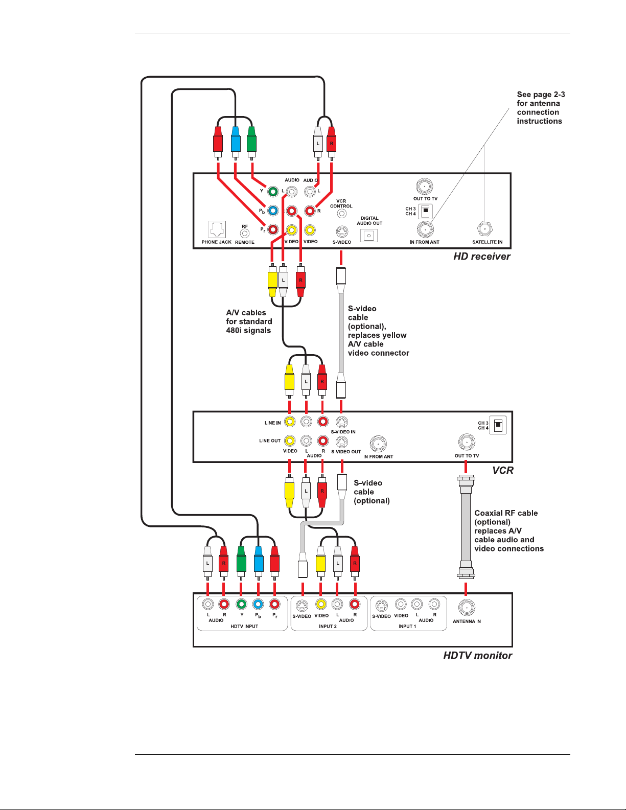
HD Receiver with HDTV Monitor and VCR
Follow these steps indicated by the diagram following this text.
1) Connect the satellite dish antenna and terrestrial antenna or cable service to the HD
receiver following the instructions in “HD Receiver and Satellite Dish Antenna with
Terrestrial Antenna or Cable Service” on page 2-3.
2) Connect one set of Component Video Cables (one green Y connector, one red P
tor, and one blue P
marked Y, P
r
monitor using the HDTV input connections marked Y, P
Note: Connect the Y, P
, and Pb connectors on your TV that are compatible with HD signals in the
P
r
connector) to the back of the HD receiver using the connections
b
, and Pb. Connect the other ends of this cable to the back of the HDTV
, and Pb.
r
, and Pb connectors of the HD receiver only to the Y,
r
connec-
r
Page 2-5
Page 24

Hughes Model HIRD-E86 Platinum HD Receiver
1080i scanning rate and that comply with the EIA 770.3 signal standards.
Refer to your television owner’s guide for verification.
3) Connect one set of audio cables (one white left audio connector and one red right audio
connector) to the back of the HD receiver using the connectors marked AUDIO L, R.
Connect the other end of the audio cables to the back of the HDTV monitor using the
audio inputs.
Note: This connection allows the use of the speakers in the TV to hear the
sound.
4) Connect a set of audio and video or S-video cables to the second set of AUDIO L, R, and
VIDEO or S-VIDEO connectors on the back of the HD receiver. Connect the other end to
the AUDIO, VIDEO, or S-VIDEO input connections on the back of the VCR.
5) Connect another set of audio and video or S-video cables to the back of the VCR using
the AUDIO and VIDEO output connection. Connect the other end of this cable to a group
of standard AUDIO, VIDEO, or S-VIDEO input connections on the back of your TV.
Note: This connection allows you to send HD receiver signals, converted to
standard 480i signals, to your VCR so they can be recorded.
You can see the playback of a video tape by selecting this input on your TV.
You can also pass HD receiver signals, converted to standard 480i, through
your VCR to your TV; however, you may need to turn on your VCR to pass
these signals.
When the HD receiver is converting all signals to standard 480i signals that
can be recorded by standard VCRs, there will be no signals on the Y, P
connectors.
P
b
, and
r
When the HD receiver is converting all signals to 1080i that can be sent to the
HDTV input of the HD monitors, there will be no standard 480i signals to send
to VCRs or standard video inputs of TVs.
For better performance, if both the TV and the VCR have S-video connectors,
use S-video cables instead of standard yellow video cables.
Note: If you have connected a VCR into your entertainment system in a way
that routes the cables from the HD receiver to your VCR before the signal
reaches the TV, you may experience a distorted picture if you attempt to record
a copy-protected program. These programs are identified by a “Can’t Tape”
symbol in the banner area of the screen. If this occurs, simply stop the
recording process and your picture will automatically correct itself.
Page 2-6
Page 25
Setting Up Your HD Receiver
Page 2-7
Page 26

Hughes Model HIRD-E86 Platinum HD Receiver
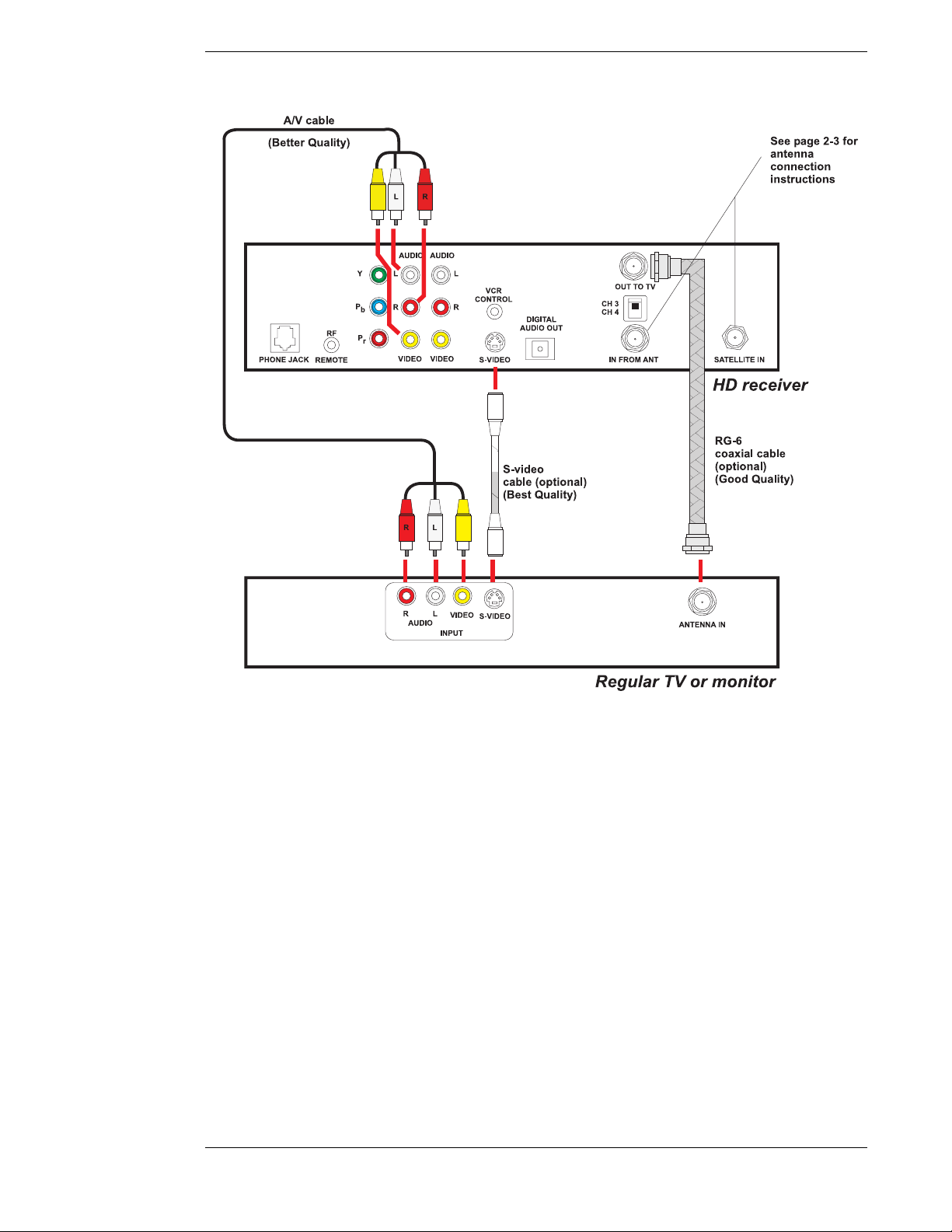
HD Receiver and Standard Definition TV Monitor
Follow these steps indicated by the diagram following this text.
1) Connect the satellite dish antenna and terrestrial antenna or cable service to the HD
receiver following the instructions in “HD Receiver and Satellite Dish Antenna with Terrestrial Antenna or Cable Service” on page 2–3.
2) Connect one set of standard audio and video cables (one yellow video connector, one
white left audio connector, and one red right audio connector) to the back of the HD
receiver using the connectors marked AUDIO L, R and VIDEO. Connect the other end
of the audio and video cable to the back of the TV monitor using the AUDIO and VIDEO
inputs.
Optional: If your TV has an S-VIDEO input, then connect one end of an S-video cable
to the back of the HD receiver using the output marked S-VIDEO. Connect the other end
of the S-video cable to the back of the TV making sure to pair the S-VIDEO input with
the previously used audio inputs. If you use an S-video cable, you will not need to use the
yellow video cable.
3) Optional: If the TV does not have AUDIO and VIDEO input connectors, then connect
one end of a coaxial RF cable to the OUT TO TV connector on the back of the HD
receiver. Connect the other end of the coaxial RF cable to the antenna input connector on
the back of the TV. Set the CH3/CH4 switch to the channel not used in your area. This is
the channel you will select on your TV to view the HD receiver.
Note: 1) When the HD receiver is in standby (power LED off), the receiver will
pass the signal received at the “In From Ant” connector out of the “Out To
TV” connector unaltered. 2) When the HD receiver is turned on and set to the
HD (1080i) output mode, the HD receiver will pass the signal received at the
“In From Ant” connector out of the “Out To TV” connector unaltered.
3) When the HD receiver is set to the SD (480i) output mode, the channel the
HD receiver has selected will be changed to channel 3 or 4 and sent out of the
“Out To TV” connector. All other channels will be blocked.
Page 2-8
Page 27
Setting Up Your HD Receiver
HD Receiver with Standard Definition TV Monitor and VCR
Follow these steps indicated by the diagram on page 2-11.
1) Connect the satellite dish antenna and terrestrial antenna or cable service to the HD
receiver following the instructions in “HD Receiver and Satellite Dish Antenna with Terrestrial Antenna or Cable Service” on page 2–3.
2) Connect one set of standard Audio and Video cables (one yellow video connector, one
white left audio connector, and one red right audio connector) to the back of the HD
receiver using the connectors marked AUDIO L, R and VIDEO. Connect the other end
of the Audio and Video cables to the back of the TV monitor using the AUDIO and
VIDEO input connectors.
Optional: For better performance, if your TV has an S-VIDEO input, then use an SVideo cable instead of a standard yellow Video cable.
3) Connect another set of standard Audio and Video cables to the back of the HD receiver
using the connectors marked AUDIO L, R and VIDEO. Connect the other end of the
audio and video cables to the back of the VCR using the AUDIO and VIDEO input connectors.
Page 2-9
Page 28

Hughes Model HIRD-E86 Platinum HD Receiver
4) Connect another set of standard audio and video cables to the back of the VCR using the
AUDIO and VIDEO output connectors. Connect the other end of this cable to another
group of unused input connectors on the back of the TV.
Note: There are possible variations to steps 2, 3, and 4 above. For example, if
your TV or monitor has only one set of AUDIO and VIDEO input connectors,
or if you have an S-VHS VCR, you may choose the following connection
variation: Connect the AUDIO and VIDEO or S-VIDEO connectors of the
HD receiver only to the VCR. Then connect the VCR output connectors to the
TV. In this situation, you may need to turn on your VCR to pass HD receiver
signals to your TV.
5) Optional: If the TV does not have AUDIO and VIDEO input connectors, then connect
one end of a coaxial RF cable to the OUT TO TV connector on the back of the HD
receiver. Connect the other end of the coaxial RF cable to the antenna input connector on
the back of the VCR. Connect another coaxial RF cable to the antenna output connector
on the back of the VCR and connect the other end of this cable to the ANTENNA or
VHF input connector on the back of the TV. Set the CH3/CH4 switch on the HD receiver
to the channel not used in your area. This is the channel you will select on your TV to
view the HD receiver.
Note: If you have connected a VCR into your entertainment system in a way
that routes the cables from the HD receiver to your VCR before the signal
reaches the TV, you may experience a distorted picture if you attempt to record
a copy-protected program. These programs are identified by a “Can’t Tape”
symbol in the banner area of the screen. If this occurs, simply stop the
recording process and your picture will automatically correct itself.
Note: 1) When the HD receiver is in standby (power LED off), the receiver will
pass the signal received at the “In From Ant” connector out of the “Out To
TV” connector unaltered. 2) When the HD receiver is turned on and set to the
HD (1080i) output mode, the HD receiver will pass the signal received at the
“In From Ant” connector out of the “Out To TV” connector unaltered.
3) When the HD receiver is set to the SD (480i) output mode, the channel the
HD receiver has selected will be changed to channel 3 or 4 and sent out of the
“Out To TV” connector. All other channels will be blocked.
Page 2-10
Page 29

Setting Up Your HD Receiver
Page 2-11
Page 30

Hughes Model HIRD-E86 Platinum HD Receiver
r
HD Receiver and Dolby® Digital Receiver or Decoder
Follow these steps indicated by the diagram below:
1) Connect an optical digital cable to the back of the HD receiver using the connector
marked DIGITAL AUDIO OUT. Connect the other end of this cable to the optical input
on the back of your Dolby Digital receiver or decoder.
2) Check the Owner’s Guide for the Dolby Digital receiver or decoder for proper set-up and
operation.
AUDIO
AUDIO
LYL
VCR
P
RR
b
RF
P
r
PHONE JACK SATELLITE IN
REMOTE
VIDEO VIDEO
CONTROL
S-VIDEO
DIGITAL
AUDIO OUT
OUT TOTV
CH 3
CH 4
IN FROMANT
HD receiver
Optical digital cable
Amplifier with
Dobly Digital (AC-3)
processing
Home theate
Page 2-12
Page 31

Setting Up Your HD Receiver
HD Receiver and Standard Stereo System
Follow these steps indicated by the diagram below:
1) Connect a set of stereo audio cables (one white left connector and one red right connector) to the back of the HD receiver using the connectors marked AUDIO L, R. Connect
the other ends of the cables to the back of your stereo system using a set of AUDIO
inputs. You may select any input except for the input marked PHONO, TT, or TURN-
TABLE. Those inputs are for turntables only and will distort the sound from any other
components.
Note: If you used both sets of connectors marked VIDEO and AUDIO L, R in
connecting your TV or VCR you will have to replace one set of the AUDIO L,
R connections as shown below.
AUDIO
AUDIO
LYL
VCR
P
RR
b
RF
P
r
REMOTEPHONE JACK SATELLITE IN
VIDEO VIDEO
CONTROL
S-VIDEO
DIGITAL
AUDIO OUT
OUT TO TV
CH 3
CH 4
IN FRO MA NT
HD receiver
LR
Audio cable
L R
Stereo audio equipment
Finishing Up
You can mix and match the different hookups described herein to suit your entertainment
system’s available connections. For example, you can connect the VCR using audio/video cables,
while the TV is connected with the RF signal using a coaxial RF cable. Always try to achieve the
highest quality audio and video and greatest flexibility possible.
Once all connections have been completed, plug in the TV, VCR, and HD receiver to the wall
outlet. Use an appropriate extension cord or surge protector if necessary. See “Important Safety
Instructions” described in the front of this manual.
Page 2-13
Page 32

Hughes Model HIRD-E86 Platinum HD Receiver
POWER
Connecting the VCR Control Cable
With the proper connections the HD receiver can control your VCR for
unattended recording.
Note: The output of the HD receiver must be in SD mode
to record using the hookup configurations previously
The VCR Control
cable and jack
described in this chapter.
Finding the VCR’s Remote Control Sensor
Plug the VCR control cable into the back of the HD
receiver. So that the HD receiver can control your
VCR, the emitter end of the VCR control cable must
be attached where the VCR’s remote control sensor
is located. This is labeled on some VCRs. You may
also find a diagram in your VCR manual indicating
the sensor position. It is commonly identifiable by a
small dark plastic window. For reference, see the
sensor on the HD receiver located behind the door.
If the sensor is not labeled or documented, you will
need to scan the front of your VCR with your VCR
remote control. Use the following procedure to
accomplish this:
● Hold the VCR remote control about ½-inch
from the front left side of your VCR.
● Slowly move the remote control to the right repeatedly pressing the remote control’s
POWER
key on and off.
Look for indications of the remote control
sensor
Scanning for the remote control sensor
● Once the VCR responds to pressing the key on the remote control, note the posi-
tion of the remote control. This should indicate the location of the VCR remote control
sensor.
Once the sensor position has been determined, temporarily attach the emitter to the area with a
piece of tape until the system can be tested. Refer to the “VCR Setup” subsection in Chapter 7,
“HD Receiver’s Menu System,” to program and test the VCR control feature.
Upon verifying that the VCR control is functioning properly, you can remove the tape and
permanently attach the emitter using the peel-and-stick backing. This attachment should not
interfere with normal VCR operation.
RF Remote Control Receiver
Your HD receiver includes an RF/IR remote control and RF receiver. With this combination you
can have complete control of your HD receiver from other rooms inside your house. The RF/IR
remote control emits a powerful radio signal that is then broadcast up to a distance of 100 feet to
the RF receiver. No tools are needed to install the RF receiver. The range of the RF remote
control is a maximum of 100 feet, however weakened batteries and some building materials in
walls, floors, and ceilings may reduce this range.
Page 2-14
Page 33

Setting Up Your HD Receiver
ACTI ON
INPUT
Connecting the RF Remote Control Receiver/
Antenna
You can place the RF remote control receiver base
behind the HD receiver or hidden elsewhere out of
view.
Plug the RF remote control receiver cable into the
RF REMOTE connector on the rear of the HD
receiver. Extend the cable and place the antenna in
the desired location. To achieve the best operating
range from the remote control, the antenna should be
placed as high and as far away from metal objects as
possible.
This completes the installation. Go to the location
where you would like to use the remote control and
try it. If you experience any problems, verify that the
batteries are strong and you are within operating
range. If you continue to have problems, try
repositioning the RF remote control receiver.
Setting the Address of Your HD
Whole House RF remote control receiver
Receiver and Remote Control
To avoid interference between your remote control and neighbors who may have a similar model
remote control, you should change the remote control broadcast address of your remote controls
and HD receiver. This is similar to choosing a channel on a cordless phone so that you and your
neighbors don’t hear each other’s conversations.
See Chapter 7, “HD Receiver’s Menu System, Advanced Preferences, Receiver ID,” for
instructions on changing the remote control address for the HD receiver.
See Chapter 8, “Programming Your Remote Control, Using the Remote Control,” for instructions
on changing the remote control address.
Now You Can Turn It On
Once you have connected everything, you can begin powering up the components. Turn the TV
on and set it to the HD input, VIDEO or S-VIDEO, or the HD receiver’s output channel (3 or 4).
Do the same for the VCR, if applicable. Now turn the HD receiver on. You will see the start-up
screen for several seconds.
Note: The HD receiver VIDEO output defaults to the Y, P
connectors when first used. If you are not using an HDTV monitor, or prefer
to use the standard video outputs, try switching the outputs of the HD receiver
from HD to SD. Using the remote control, press the button once, then
press the button, followed by the button. Pressing this sequence
INPUT
SAT
of keys will switch the receiver between the High Definition (1080i) output
mode and the Standard Definition (480i) output mode. Following one or more
of this sequence, your picture should appear. This is not a toggle
ACTI ON
process, but instead tells the receiver to output HD or SD depending upon
which command was sent to the receiver most recently.
, and Pb HD
r
Page 2-15
Page 34

Hughes Model HIRD-E86 Platinum HD Receiver
▲
You can also achieve this from the front panel by pressing the and
GUIDE
keys simultaneously.
POWER-ON Screen
As power is applied to the HD receiver for the first time
after being plugged in or after a power failure, the
POWER-ON screen, shown on the right, is displayed.
The screen will not appear each time you press the
Powe r button.
A panel will display an Exit and an Installation button.
Below that, a progress meter will display illuminated
boxes, which will progressively light up from left to
right as the system powers up.
The POWER-ON screen
Exit
Highlighting the Exit button on the screen and pressing
SELECT
the key on the remote control causes an exit from the POWER-ON screen and interrupts
the Guide data acquisition.
Installation
If the power is on, but the satellite dish antenna or local area antenna or cable system inputs are
not yet installed, highlighting the Installation button and pressing the key on the remote
control will display the INSTALLATION screen. Read Chapter 4 for installation and testing
instructions.
SELECT
If the satellite is properly pointed, the program guide is loaded when power is applied. You can
exit out of this start up process, but you would not load the current guide data. Allow time for this
program data to load.
Note: If your satellite dish is properly pointed and receiving a signal, this bootup process is necessary to completely load the Advanced Program Guide™
information. If you exit this screen before it is complete, or have yet to install
the satellite dish, this process will take place later. Loading Advanced Program
Guide™ data can take several minutes.
If you are using the HD receiver with only the terrestrial antenna or cable
signal, you can immediately exit this screen.
Page 2-16
Page 35

Controlling the HD
▲
▲
Receiver
3
Now it’s time for you to take control. Take a few minutes to read through this chapter to
understand how to operate your system. Let’s begin with a couple of simple rules. First, there is
nothing that you can do, using the front panel keys or the remote control keys, which could harm
the HD receiver in any way. Once you understand the capabilities and options available in your
receiver, you’ll be able to undo any changes or settings that you make.
It is not necessary to know everything your system can do right away. As you use the HD
receiver, the techniques necessary to control it will become second nature.
Front Panel vs. Remote Control Keys
The front panel provides all the basic controls needed to access and use the primary features of
the HD receiver. The remote control has additional keys to provide shortcuts or access to
extended features of the HD receiver. Most of the remote control keys can also be used to control
other components in your entertainment system. For this reason, you must remember to press the
SAT
key, putting the remote control in HD receiver mode, when you want to control the HD
receiver.
Basic Navigation
The most common HD receiver-related keys that you will use are , , , , and . Four
distinct keys on the HD receiver front panel represent the direction keys. On the remote control,
the direction keys are represented by the top, bottom, left, and right keys surrounding the
key. These keys are primarily used to move the highlight (also known as a cursor) around the
screen. Press the key to activate a highlighted item.
Another key you will be using frequently is the key, located on both the front panel of the
HD receiver and on the remote control. This key is used when you want to display the current onscreen guide. Once you are in the guide, pressing the key while a program title is
highlighted will display the Guide pop-up menu.
Another key appearing on both the front panel and the remote control is the key. This key
is used to retrieve descriptive information about a currently airing event and to provide access to
scheduling information (and purchasing information for pay per view) about highlighted
programs in the on-screen guide.
The final key that appears on both the remote control and the front panel is the key. Make
sure the remote control is in “SAT” mode for the key to control the HD receiver. When
you turn the HD receiver off, it has not actually stopped using electricity. Rather, it goes into a
standby mode that enables it to continue monitoring data sent from DIRECTV, call in status
reports to DIRECTV, start and stop your VCR for programs you have scheduled, receive
messages, and perform other background activities.
SELECT
GUIDE
GUIDE
POWER
▲
▲
SELECT
SELECT
INFO
POWER
Page 3-1
Page 36

Hughes Model HIRD-E86 Platinum HD Receiver
EXIT
There are two keys on your remote control that most people use frequently. They are the
and the keys.
EXIT
FAV
After you have established favorite channel lists, as described in Chapter 7, “HD Receiver’s
Menu System,” you can use the key to cycle through them quickly and easily. Each press
of the key will advance to the next list of channels. After stepping through the favorite
FAV
FAV
lists, it will cycle back to “All Channels.”
At any time, you can exit the on-screen guide by selecting Video in the Guide pop-up menu. An
even faster way is to press the key. The key also clears all inputs and menus, and
EXIT
returns to the program you were watching.
Page 3-2
Page 37

Setting Up the
Satellite Dish
4
Antenna and
Terrestrial Inputs
There is a cluster of DIRECTV satellites in space, and, just as a telescope is pointed at a star, you
need to point your satellite dish at the satellites. In this chapter, we will explain how to configure
your receiver for your satellite dish antenna, where to point your satellite dish antenna, and how
to configure your receiver for analog or digital terrestrial (broadcast or cable) reception.
It is recommended that you have the satellite dish and terrestrial antennas professionally
installed. If you choose to install the antennas yourself, please pay special attention to the
precautions in the front of this manual and refer to the installation instructions packaged with the
satellite dish antenna.
Your satellite dish antenna will need to be pointed at a satellite cluster located 22,300 miles in
orbit above the equator. To aim the satellite dish antenna at the satellites, you need to know the
azimuth, elevation, and tilt angles. The HD receiver will assist you in determining these angles.
Set-up of the satellite dish antenna and terrestrial inputs will be explained in three parts:
1) Installing and testing the satellite dish antenna by itself first.
2) Setting up and testing terrestrial or cable inputs.
3) Setting up and testing terrestrial or cable inputs by themselves, without a satellite dish
antenna.
Installing and Testing the Satellite Dish Antenna
Installing your dish antenna involves four separate steps:
● Selecting the correct type of satellite dish antenna.
● Finding the correct dish antenna pointing coordinates.
● Pointing the dish antenna.
● Testing the strength of the satellite signal.
Page 4-1
Page 38

Hughes Model HIRD-E86 Platinum HD Receiver
▲
▲
▲
▲
SELECT
▲
▲
Displaying the INSTALLATION Screen
Highlighting the Installation button on the POWERON screen (explained on page 2-15) and pressing the
SELECT
key on the remote control will display the
INSTALLATION screen shown on the right.
If this is not the first time the HD receiver is turned
on after being plugged in, follow these steps:
● Open the MAIN MENU screen by pressing
ACTI ON
the key followed by the key on
the remote control.
GUIDE
● Using the and keys, highlight the Setup
Menu Button then press the key on
SELECT
The INSTALLATION screen
the remote control to display the SETUP
menu.
● Using the and keys, highlight the Installation Button then press the key on the
SELECT
remote control to display the INSTALLATION screen.
Selecting the Correct Type of Satellite Dish Antenna
You need to select the correct type of dish antenna that you have connected, so that the HD
receiver can calculate the correct coordinates for pointing the dish antenna.
Highlighting the Dish Setup button on the
INSTALLATION screen and pressing the
key on the remote control will display the DISH
SETUP screen. Highlighting the Dish Type button
on the DISH SETUP screen and pressing the
key on the remote control will display the DISH
TYPE pop-up menu. Press the and keys to
highlight the type of dish antenna that is connected
to the HD receiver and then press the key.
Dish Type Selections
Note: You must select the correct
dish antenna type to obtain correct pointing results.
SELECT
SELECT
The DISH SETUP pop-up menu
These are the following dish antenna type selections:
None Highlight this selection if you are not connecting a dish antenna, but are
connecting a terrestrial antenna or cable signal.
Round Dish Highlight this selection if you connected an 18" round dish antenna. This
setting allows the HD receiver to receive a signal from the main satellite,
located at 101°.
Note: A round dish antenna will not receive High Definition satellite signals
from DIRECTV.
Page 4-2
Page 39

Setting Up the Satellite Dish Antenna and Terrestrial Inputs
▲
▲
▲
▲
Oval Dish 2 Highlight this selection if you connected a DIRECTV PLUS™ oval dish
antenna with two LNBs. This setting allows the HD receiver to receive signals
from Satellite A at 101° and Satellite B at 119°, enabling reception of
DIRECTV High Definition programming throughout the United States as
well as local stations in specific cities. Most users will have this type of dish.
Oval Dish 3 Highlight this selection if you connected a DIRECTV PLUS™ oval dish
antenna with the optional Satellite C LNB kit purchased separately from your
local satellite system installer. This setting allows the HD receiver to receive
signals from Satellite A at 101°, Satellite B at 119°, and Satellite C at 110°,
enabling the reception of local stations in additional specific cities in the
United States.
Cancel Highlight this selection to return to the DISH SETUP screen without making
a dish antenna type selection.
Highlighting a selection button as explained immediately above and pressing the key on
SELECT
the remote control will confirm the selection and return to the DISH SETUP screen.
Finding the Correct Antenna-pointing
Coordinates
The POSITION pop-up menu will provide you with
the correct coordinates to point your dish antenna. This
is important to receive all of the channels you are
entitled to when you subscribe to DIRECTV.
Highlighting the Position button on the DISH SETUP
menu and pressing the key on the remote control
will display the POSITION pop-up menu. Using the
and keys, and highlighting either the ZIP Code or
Latitude/Longitude button and pressing the key
on the remote control will display the corresponding
pop-up menu.
To select a digit, use the number keys or the and keys on the remote control to enter your ZIP
Code or Latitude and Longitude. After the last number has been entered, highlight the OK button
and press the key on the remote control to confirm the entry. The RESULTS screen will
SELECT
display. Highlighting the cancel button and pressing the key on the remote control will
return to the DISH SETUP menu.
SELECT
SELECT
The ZIP Code pop-up menu
SELECT
Page 4-3
Page 40

Hughes Model HIRD-E86 Platinum HD Receiver
SELECT
SELECT
▲
▲
SELECT
Pointing the Dish Antenna
The HD receiver will calculate the correct pointing
coordinates and then display this information on the
RESULTS screen shown on the right. Write down
this Elevation, Azimuth, and Tilt information. Then
highlighting the OK button and pressing the
key on the remote control will return to the DISH
SETUP Menu. Use the coordinates from the
RESULTS screen to point your dish antenna at the
sky. The separate installation instructions that come
with the dish antenna will explain exactly how to use
the Elevation, Azimuth, and Tilt information.
Note: The round dish has no tilt
information.
Testing Signal Strength
The INSTALLATION screen shown at the right will
display the strengths of signals from the different
satellites and the transponders on each satellite. The
screen displays a numerical strength indication and a bar
graph accompanied by an audible tone to indicate signal
strength. The higher the number, the greater the amount
of the bar graph occupied, or the faster the beeping tone,
the stronger the signal.
The RESULTS screen
You should test the signals from each of the satellites
that match the type of dish that you selected on the
DISH TYPE screen.
The INSTALLATION screen
Highlighting the Source button on the
INSTALLATION screen and pressing the key
SELECT
on the remote control will display the Signal Source
pop-up menu shown at the right. Highlighting the
Satellite A (101°), Satellite B (119°), Satellite C (110°),
or Local Digital Terrestrial and pressing the
key on the remote control will return to the
INSTALLATION screen and show the signal strength
for the selected source.
Local Providers
The Signal Source screen
The LOCAL PROVIDERS screen allows DIRECTV
to add local channels to the Advanced Program Guide™ in the same way that it lists satellite
program information.
Highlighting the Dish Setup button on the INSTALLATION screen and pressing the key
SELECT
on the remote control will display the DISH SETUP screen. Using the and keys, highlight
these Local Provider area options and press the key on the remote control.
Page 4-4
Page 41

Setting Up the Satellite Dish Antenna and Terrestrial Inputs
Local Provider Area Options
Area 1 You have connected a standard VHF/UHF antenna for receiving your primary
analog and digital terrestrial signals. The ZIP Code entered here will specify
what terrestrial program information should appear in the Advanced Program
Guide™.
Area 2 Area 2 may be a neighboring city or distant terrestrial station you wish to
receive from the same VHF/UHF antenna used in Area 1. The ZIP Code
entered here will specify what terrestrial program information should appear
in the Advanced Program Guide™.
Cable TV You have connected a cable television service. The cable provider entered
here will specify what cable program information should appear in the onscreen program guide.
System Test
The SYSTEM TEST screen will display the signal strength of all of the transponders on the
satellite that have been selected on the Signal Source pop-up menu. It will also indicate the
quality of the signal transfer between the dish antenna and the HD receiver. The SYSTEM TEST
Menu offers the following options:
Begin Test Starts the receiver test, which provides basic status information about the
receiver. The test may take up to one minute.
Cable Test Tests and displays indicators of all transponder signals from the satellite
chosen by the Source pop-up menu.
Upgrade Checks the status of software upgrades that DIRECTV periodically performs.
Highlighting the System Test button on the INSTALLATION screen and pressing the key
on the remote control will display the SYSTEM TEST screen. Using the and keys, highlight
either the Begin Test or Cable Test button and press the key on the remote control. After a
SELECT
▲
SELECT
▲
short period of time, the results of the test will be displayed.
You should perform the cable test for each of the
satellites supported by the dish antenna you selected in
the DISH TYPE screen. If you are setting up your
system to receive signals from Satellites B (110°) and
C (119°), you will need to change source satellites
between each Cable Test.
Note: Not all of the transponders on Satellites
B (119°) and C (110°) are currently being
used. On Satellite B, for example, you may
receive NA (Not Available) indications for
several transponders. This is normal.
The SYSTEM TEST screen
Page 4-5
Page 42

Hughes Model HIRD-E86 Platinum HD Receiver
When you have received a strong signal from several transponders on each of the satellites you
are setting up, you have completed the setup for digital satellite channels. A numeric value for the
signal strength ranges from 0 to 99. While your signal strength may vary, refer to the following
map to determine the suggested signal strength for your area:
70s
80s
80s
90s
Typical signal strength results. Your actual signal strength may vary.
Check to see if you are receiving the DIRECTV Promotional Channel on Channel 100. If you are
receiving that channel, you can now telephone 1-800 DIRECTV to subscribe to DIRECTV
Programming®. If you have difficulties receiving a strong signal on one individual satellite,
the pointing of the dish antenna will need fine tuning.
Fine Tuning the Pointing of the Dish Antenna
It often takes two people to fine tune the pointing of the dish antenna. One person watches the
signal strength indicator on the INSTALLATION screen and relays the information to another
person who is adjusting the dish antenna. To fine tune the pointing of the dish antenna, you will
need to select a satellite on the Source pop-up menu. Then select one or more transponders from
that satellite by using the XPONDER pop-up menu. Once the pointing of the dish antenna has
been fine tuned to receive a strong signal from Satellite A (101°) and Satellite B (119°), the
pointing of the dish antenna at Satellite C (110°) should be correct.
Selecting Transponders
The XPONDER pop-up menu will display the signal strength from individual transponders on
each of the satellites. A transponder is a group of circuits on the satellite that transmits the
satellite channels. There are numerous transponders on each satellite; however, not all of the
transponders will be in use. All of the transponders on Satellite A will provide some signal
strength indication. But not all the transponders on Satellites B and C may be fully utilized at this
time.
To check the signal strength of individual transponders, first select the satellite using the Source
pop-up menu. Then highlighting the Xponder button on the INSTALLATION screen and
pressing the key on the remote control will display the XPONDER pop-up menu. Use the
Page 4-6
SELECT
Page 43

Setting Up the Satellite Dish Antenna and Terrestrial Inputs
▲
▲
▲
▲
▲
▲
and buttons to select different transponders. Observe the signal strengths of the different
transponders. Adjust the dish antenna to improve the signal strengths. After fine tuning,
highlighting the Done button and pressing the key on the remote control will display the
INSTALLATION screen. Highlighting the Video button and pressing the key or pressing
EXIT
the key on the remote control will display the channel last viewed.
SELECT
SELECT
Adding Terrestrial Antenna or Cable to Your
Satellite Connections
If you connected a terrestrial antenna or local cable TV
service to view local analog or digital channels, you
need to configure the HD receiver to receive those
broadcasts.
Highlighting the Local Area button on the
INSTALLATION screen and pressing the key
on the remote control will display the LOCAL AREA
screen shown at the right. Using the and , highlight
either the Local In 1 button if you connected your
terrestrial antenna or cable service to the jack labeled
IN FROM ANT, or highlight the Local In 2 button if
you connected the jack labeled SATELLITE IN and
used a Diplexer to combine your terrestrial antenna cable with the cable from the satellite dish
antenna. Then press the key on the remote control to display the Local In pop-up menu.
SELECT
SELECT
The LOCAL AREA screen
On the Local In pop-up menu, use the and keys to highlight the buttons for the type of
antenna or cable you connected to the HD receiver, and then press the key on the remote
SELECT
control.
Local In Connection Options
The connection options found on the Local In 1 and
Local In 2 pop-up menus are:
None You are not connected to an antenna
or cable.
Antenna You have connected a standard
VHF/UHF indoor or outdoor
antenna.
Cable TV (STD) You have connected a cable service
that uses a standard type of cable
signal.
Cable TV (HRC) You have connected a cable service that uses the HRC type of cable signal.
Cable TV (IRC) You have connected a cable service that uses the IRC type of cable signal.
Note: Consult your cable company to find out what type of cable signal you have.
Note: Local In 1 and Local In 2 must have different input signal types. The receiver
does not support the simultaneous connection of two terrestrial antenna signals or two
cable signals.
Local In 1 pop-up menu
Page 4-7
Page 44

Hughes Model HIRD-E86 Platinum HD Receiver
▲
▲
▲▲▲
▲
▲
▲
After selecting your Local In connection and pressing the key on the remote control, the
SELECT
LOCAL AREA screen will be displayed.
Clear
Remove all the check marked channel numbers from the local Area screen.
Scan Channels
This option will automatically scan through all of the possible channels and place the active
channel numbers into the Advanced Program Guide™ grid. NTSC (analog) channels will be
listed by their normal one- or two-digit Channel Number. ATSC (digital) channels will be listed
by the Channel Number followed by a hyphen and a number other than zero. An example of an
ATSC channel would be 23-1. At this time, the program information for local NTSC and ATSC
channels that is shown on the Advanced Program Guide™ will simply display “Regular
Schedule.” To receive accurate program information for these channels, you need to select a local
cable provider or enter area ZIP Code on the DISH SETUP screen.
Testing the Strength of the Terrestrial Digital Channels
The INSTALLATION screen will display the strengths
of signals from the terrestrial digital channels. The
screen displays a numerical strength indication and a
bar graph accompanied by an audible tone to indicate
signal strength. The higher the number, the greater the
amount of the bar graph occupied, or the faster the
beeping tone, the stronger the signal.
You should test the signal strength of each digital
channel by “physical” Channel Number, not by
“virtual” Channel Number. The “physical” Channel
Number is the channel number that the FCC uses to
The INSTALLATION screen
identify the channel frequency, and it is a one-digit or
two-digit number. The “virtual” Channel Number is the number that a local broadcast station
wishes to use to identify itself. For instance, if the number for your local CBS analog channel is 2
(Channel 2), then that station may use 2-1 as a digital “virtual” Channel Number, even though the
“physical” number assigned by the FCC to that channel is 40.
To test the strength of terrestrial digital channel signals, highlighting the Source button on the
INSTALLATION screen and pressing the key on the remote control will display the
SELECT
SOURCE pop-up menu. Using the and keys to highlight the Local Digital button on the pop-
up menu and pressing the key on the remote control will display the LOCAL DIGITAL
SELECT
Signal Strength Screen. Use the and keys on the remote control to move to the column on the
left and use the and to highlight the Channel button. Press the key on the remote
SELECT
control to display the CHANNEL pop-up menu.
If you know the “physical” numbers for your local channels, use the number buttons on the
remote control to select each channel number, and observe the signal strength. If you do not know
these “physical” channel numbers, use the and keys on the remote control to change the
channel one number at a time. Channels with a signal strength of less than 60 may require a better
antenna, adjustment of the antenna angle, or the antenna may be too far away from the signal
source.
Page 4-8
Page 45

Setting Up the Satellite Dish Antenna and Terrestrial Inputs
▲
▲
▲
▲
After fine-tuning, highlighting the Done button and pressing the key on the remote control
will display the INSTALLATION screen. Highlighting the Vid eo button and pressing the
SELECT
SELECT
key on the remote control will display the channel last viewed. You may also use the Exit key on
the remote control to exit all menus and return to the last viewed channel.
Terrestrial Antenna or Cable without
a Satellite Connection
If you connected a terrestrial antenna or local cable TV service to view local analog or digital
channels, you need to configure the HD receiver to receive these broadcasts.
Highlighting the Local Area button on the INSTALLATION screen and pressing the key
on the remote control will display the LOCAL AREA screen. Using the and keys, highlight
either the Local In 1 button if you connected your terrestrial antenna or cable service to the jack
labeled IN FROM ANT. Or, highlight the Local In 2 button if you connected your terrestrial
antenna to the jack labeled SATELLITE IN. Then press the key on the remote control to
SELECT
display the Local In pop-up menu.
On the Local In pop-up menu, use the and keys to highlight the buttons for the type of
connection made to the HD receiver, and then press the key on the remote control.
SELECT
Local In Connection Options
The connection options found on the Local In 1 and Local In 2 pop-up menus are:
SELECT
None You are not connected to an antenna or cable.
Antenna You have connected a standard VHF/UHF indoor or outdoor antenna.
Cable TV (STD) You have connected a cable service that uses a standard type of cable signal.
Cable TV (HRC) You have connected a cable service that uses the HRC type of cable signal.
Cable TV (IRC) You have connected a cable service that uses the IRC type of cable signal.
Note: Consult your cable company to find out what type of cable signal you have.
After selecting your Local In connection and pressing the key on the remote control, the
SELECT
LOCAL AREA screen will be displayed.
Note: Local In 1 and Local In 2 must have different input signal types. The
receiver does not support the simultaneous connection of two terrestrial
antenna signals or two cable signals.
Page 4-9
Page 46

Hughes Model HIRD-E86 Platinum HD Receiver
▲
▲
▲
▲
SELECT
▲
▲
Scan Channels
This option will automatically scan through all of the
possible channel frequencies and place the active
channel numbers into the program guide grid. NTSC
(analog) channels will be listed by their normal one or
two Channel Number. ATSC channels will be listed by
their one or two digit main channel number followed by
a hyphen and a number of 1 or greater. At this time, the
program information for local NTSC and ATSC
channels that is shown on the program guide will
simply display “Regular Schedule.” To receive accurate
program information for these channels, you need to
Channel Scan
connect to a satellite dish and download this
information from DIRECTV.
Selecting the Correct Satellite Dish Type for Terrestrial-only
Operation
If you have a terrestrial-only antenna hookup (that is, no satellite dish), you must configure the
HD receiver for a dish type of “None” so it will not search for a satellite signal.
Highlighting the Dish Setup button on the INSTALLATION screen and pressing the key
SELECT
on the remote control will display the DISH SETUP screen.
Highlighting the Dish Type button on the DISH SETUP screen and pressing the key on the
SELECT
remote control will display the DISH TYPE pop-up menu. Using the and keys, highlight dish
type “None” and press the key.
SELECT
Editing Local Channels
To remove or add local NTSC analog and ATSC digital channels in the channel list, use the and
keys to highlight the specific channel. Press to remove the checkmark and the channel
from the channel list. Press again to add it back.
SELECT
Time Setup
You can set the current time and day, the current date,
the time zone, and whether or not you observe daylight
saving time. This option is only available if you have
selected NONE as your DISH TYPE.
Use the and buttons to move around the TIME
SETUP screen, then press SELECT to select an item,
and you can use your remote control to enter numbers.
When you subscribe to DIRECTV, the time will be
automatically set and you cannot reset it. You can,
however, reset the time zone and whether you observe
daylight saving time.
Time Setup screen
Installation Is Now Complete
The installation and testing of the satellite dish antenna and/or terrestrial inputs is now complete.
You are ready to enjoy your system.
Page 4-10
Page 47

Watching Local
Terrestrial and
5
®
DIRECTV
Programming
Types of Channels
This chapter will reveal many different ways to find programs you want to watch. The first thing
you should know is how channels in the DIRECTV Advanced Program Guide™ are arranged.
Analog (NTSC) Channels without Dish Connection
Analog (NTSC) channels received by terrestrial antenna or cable service when a dish antenna has
not been connected will be listed by their traditional single- or double-digit Channel Number. The
program information will simply state “Regular Schedule.”
Analog (NTSC) Channels with Dish Connection
Analog (NTSC) channels received by terrestrial antenna or cable service when a dish antenna has
been connected will be listed by their traditional single- or double-digit Channel Number and the
station’s call letters or network logo. The program information area will display the program
name and description if this channel is supported for your zip code area.
Digital (ATSC) Channels without Dish Connection
Digital (ATSC) channels received by a terrestrial antenna or cable service when a dish antenna
has not been connected will be listed by a single- or double-digit Channel Number followed by a
hyphen and a Sub-channel Number of 1 or greater; for examples: 23-1 or 23-2. The main Channel
Number can be either the “physical” Channel Number assigned to the broadcast frequency by the
FCC or a “virtual” Channel Number assigned by the broadcast station. The type of number,
“physical” or “virtual,” depends on information sent by the broadcaster. The channel call letters
or network name may also be included by the broadcaster. The program information will simply
state “Regular Schedule.”
Digital (ATSC) Channels with Dish Connection
Digital (ATSC) channels received by a terrestrial antenna or cable service when a dish antenna
has been connected will be listed by a single- or double-digit Channel Number followed by a
hyphen and a Sub-channel Number of 1 or greater; for examples: 23-1 or 23-2. The main
Channel Number can be either the “physical” Channel Number assigned to the broadcast
frequency by the FCC or a “virtual” Channel Number assigned by the broadcast station. The type
of number, “physical” or “virtual,” depends on information sent by the broadcaster or DIRECTV.
The program information area will display the program name and description if this channel is
supported for your zip code area.
Page 5-1
Page 48

Hughes Model HIRD-E86 Platinum HD Receiver
0
Local Channels from DIRECTV
Local channels from DIRECTV, when available and subscribed to, will be listed as traditional
channel numbers along with the network logo or call letters.
DIRECTV® Programming
DIRECTV programming will be listed with network logo and channel numbers 100 to 9999. For
example, the DIRECT TICKET™ movie preview channel is channel 100.
Basic Channel Changing
There are many ways to “surf” (move from channel to channel) through the available
programming. You already know two ways to change channels. The first of these is by using the
and keys on the remote control. Each key press takes you to the next available channel
in the direction that you selected.
The second way is to enter the Channel Number of the desired channel. For example, to go to the
DIRECT TICKET movie preview channel, press on the remote control.
1 0
Note: if the channel does not change right away, press the key on the
SELECT
remote control to instruct the HD receiver that you have finished entering
channel number digits.
You can enter the number for any channel that you wish.
To select a terrestrial ATSC (digital) channel, enter the main channel number followed by the
hyphen key, then the sub-channel number, and then press the key on the remote
— SELECT
control.
Channel Banner
Every time you select a channel while you are watching
TV, a Channel Banner, such as that shown to the right,
will be displayed at the top of the screen. You can also
display the banner by pressing the key on the
remote control or on the front panel of the receiver. This
banner also displays channel-related symbols where
applicable. These symbols are shown below.
The following icons may be displayed on the channel
banner. Subsequent sections will explain how to access
these features.
INFO
The CHANNEL BANNER screen
Icon ALT.
Meaning Pay Per
View
Page 5-2
AUDIO
Other audio
available
Closed
caption
available
NEW
MAIL
Unread mail Limits
enforced
Limits over-
ride
CAN’T
TA PE
Taping not
allowed
Dolby
Digital
audio
available
Page 49

Watching Local Terrestrial and DIRECTV® Programming
EXIT
▲
▲
—
The Information Banner
Pressing the key on your remote control or the
front panel while the Channel Banner is displayed will
add a description of the current program. This is called
the Information Banner. Either of these banners will
go away after a few seconds, or you can press the
key for the second time or the key to clear them.
INFO
INFO
The OneLine™ Guide
If you’d like to know what’s on another channel without
switching from your current channel, use the OneLine
Guide. Simply press or to begin browsing. You can
see the channel call sign and number, logo, and program
title(s). When you see something you like, then press
SELECT
to tune to the channel.
The CHANNEL BANNER with description
You may also directly enter a channel number to advance
the OneLine Guide to that channel. The other filter
ACTI ON
keys, including for movies, for
sports, and for news, as well as the key
ACTI ON
1
3 FAV
ACTI ON
2
will also control the content of the OneLine Guide.
Pressing the key will cancel the OneLine Guide.
EXIT
TurboTune™
The Turbo Tun e feature provides access to nine of your
preferred channels on top of the current video. The
TurboTune panel is displayed by pressing the remote
control key while watching the video as long as
there are no messages prompting you to press for
some other purpose. TurboTune is also accessible from
the front panel key. The TurboTune panel
displays nine channel tags. These channels can be
specified via the TurboTune button on the SETUP
MENU. The header area of the panel displays the title of
the highlighted channel tag. You can choose one of the
nine by moving the highlight over the desired channel
and pressing .
SELECT
SELECT
SELECT
SELECT
Note: A shortcut to moving the highlight is to press the number on the remote
control that corresponds with the on-screen position of the logo for the desired
channel. Example, press , then for the upper left channel.
SELECT 1
The OneLine™ Guide
The TurboTune™ popup
AlphaTune
Using AlphaTune, you can select a channel by spelling the channel’s call sign. To use AlphaTune,
press the key and the key on the remote control, one after the other. The
ACTI ON
ALPHA
Page 5-3
Page 50

Hughes Model HIRD-E86 Platinum HD Receiver
▲
▲
symbol will appear on the screen. You can now enter numbers and letters (letters are located
above the number keys) to spell a channel’s call sign. For example, to tune to ESPN, press the key
sequence . All special symbols such as the ampersand (&), forward
ACTI ON
slash (/), exclamation point (!), and others are found in the key. As soon as the receiver can
— 2 7 6 5
0
determine what channel you are seeking, it will tune to it automatically. No additional keys need
to be pressed.
If the channel call sign contains fewer than four letters, you may need to press the key
SELECT
after the letter sequence to indicate that you have entered enough letters. If more than one channel
call sign shares the same set of keys (for example, CNN and COM both use 155), one channel
will be displayed. If that is not the channel you want, press , one after
ACTI ON
ACTI ON
—
—
the other, and the next channel sharing the same set of keys will appear.
With experience, you will become more familiar with the channel name abbreviations that are used.
Alternate Services
The HD receiver can support alternate audio services.
To determine if the services are available for a particular
program, look for their icons below the data and time in
the Channel Banner or on the on-screen guide. To use
these services when available, press the key and
PREV
key on the remote control, one after the other. The
CH
Alternate Services banner, shown at the right, will
appear at the bottom of the screen.
Audio
Once you have selected the Audio button you can use
the and keys to step through the audio tracks offered
for the current program.
ACTI ON
The Alternate Services panel
To choose the highlighted language, press . On occasion an audio track may be offered that
SELECT
is not being broadcast. If this is the case, you will hear either unchanged audio or silence.
SAP (Secondary Audio Program) sound is not available on local analog channels received from a
terrestrial antenna or cable TV service.
Closed Caption
Closed Caption allows you to change the caption display mode for the program being watched
and to turn it on or off. If the closed caption setting in the A/V menu is set to OFF or to a different
caption setting, then the selection chosen on this screen is temporary and will be canceled when
you change channels. This setting does not affect the closed caption setting of your TV.
If the closed caption setting in the A/V menu is set to off or to a different caption setting, then the
selection chosen on this screen is temporary and will be canceled when you change channels.
Page 5-4
Page 51

Advanced
Program Guide™
6
Program Guide
The most powerful feature of the HD receiver is the DIRECTV Advanced Program Guide™. You
may customize the on-screen guide to list only channels or programs of interest to you. Other
advanced features available from the on-screen guides, such as scheduling and program
information, will help plan your viewing. Continue reading to learn the real power of the HD
receiver’s on-screen guides or Advanced Program Guide™. At any time you can press the
key to display the current on-screen guide.
This HD receiver offers a variety of on-screen guides. Each guide has its own design to make
finding programs of interest an easy task. These guides include the PROGRAM GUIDE (SM.
CELL), PROGRAM GUIDE (LG. CELL), and LOGO GUIDE.
Each guide can be filtered into smaller channel groupings, as specified in your personalized
favorite Channel Lists. You can also reduce the displayed listing by specifying a Theme of
interest, and then narrow the offerings further by specifying a type within the Theme. Additional
settings, such as Guide Times and Channel List, may be specified to determine the guide content.
A full description of the filtering options can be found later in this chapter.
GUIDE
Note: Most Program Guide features will not be available if the HD Receiver is
used without a satellite connection.
PROGRAM GUIDE Screen
Pressing the button on the remote control will
display the PROGRAM GUIDE screen shown at the
right. The guide is available in three formats: Large
Cell, Small Cell, and the Logo Guide.
GUIDE
The PROGRAM GUIDE screen
Page 6-1
Page 52

Hughes Model HIRD-E86 Platinum HD Receiver
PROGRAM GUIDE Pop-up Menu
Pressing the key on the remote control a second
time will display the PROGRAM GUIDE pop-up
menu, shown at right. On the left side are the buttons
Main Menu, Video, Guide Style, and Guide Sort. On
the right side are the buttons Descriptions, Theme
Filters, Channel List, Guide Times, and Watchword.
These buttons are explained in the following sections.
GUIDE
Main Menu
The PROGRAM GUIDE pop-up menu
Highlighting the Main Menu button on the pop-up
menu and pressing the key on the remote control will display the MAIN MENU screen
SELECT
shown and explained on page 7-2.
Video
Highlighting the Video button on the pop-up menu and pressing the key on the remote
control will return you to the last program you were viewing.
SELECT
Choosing the Guide Style
To display the on-screen guides, press the key.
Press the key again to display or remove the
GUIDE
guide pop-up menu.
To choose a guide style, simply highlight the Guide
Style button and press . A pop-up menu shown
SELECT
at right offering each of the guide styles will be
displayed. Highlight your selection and press the
SELECT
key. The guide will be redrawn to display your
selection.
Familiarize yourself with the benefits of each guide
style.
GUIDE
The GUIDE STYLE pop-up menu
PROGRAM GUIDE (Large Cell)
The PROGRAM GUIDE (Large Cell) shown below displays two hours of programming
information. Up to eight lines of channel information can be seen on the screen at one time.
The number of lines is reduced to six if the program description option is selected.
The LARGE CELL screen
with description
Page 6-2
The LARGE CELL screen
without description
Page 53

Advanced Program Guide™
▲
▲
▲
▲
The term “Large Cell” means that there are two lines of text associated with each program title.
While this provides more space for the program titles and Channel Tags, it also reduces the
number of channels for which information can be seen on the screen at one time.
The largest area of the PROGRAM GUIDE (Large Cell) is made up of cells known as the
program grid. Some cells have arrows indicating that the program started at an earlier time, or
continues until a later time, than the time displayed on the grid. The length of each grid cell
approximates the duration of the associated program.
A time line spanning the width of the guide indicates the show times of the programs being
displayed. The list of blocks running down the left-hand side are the “channel tags.” Depending
on the Guide Sort (Name or Number) option specified in the Guide pop-up menu, the tags may
display the channel numbers or call signs. This will dictate whether the channels are listed by
channel number or alphabetically by call sign.
To navigate the guide, use the , , , and keys on the remote control. You can continue to
▲
▲
press the or keys on the remote control to scroll more program information on the screen.
Pressing the key on the remote control while highlighting any title will display the
INFO
INFORMATION screen.
Use the and keys on the remote control to scroll through the guide entries one page at a
time.
When the highlight is in the grid, use the or keys on the remote control to move the highlight
▲
▲
left or right. If you move the highlight on to the Channel Tags in the leftmost column, they will
reverse themselves: they will turn from Channel Numbers to Call Signs or from Call Signs to
Channel Numbers.
Move the highlight to the right, using the keys on the remote control, to move the grid area to
▲
reveal later time periods. Sometimes after scrolling a few hours ahead, there may be a brief delay
while more information is received from the satellite.
Page 6-3
Page 54

Hughes Model HIRD-E86 Platinum HD Receiver
▲
▲
▲
▲
PROGRAM GUIDE (Small Cell)
The PROGRAM GUIDE (Small Cell) screen shown below displays 1-½ hours of programming
information. Up to 12 lines of channel information can be seen on the screen at one time. This
number of lines is reduced to 9 if the program description option is selected.
The SMALL CELL screen
without description
The SMALL CELL screen
with description
The term “Small Cell” means that there is only one line of text associated with each program
title. While this can cause the title to be cut short, or abbreviated, it also permits information
about more channels to be seen on the screen at one time.
A time line spanning the width of the guide indicates the show times of the programs being
displayed. The list of blocks running down the left-hand side are the channel tags. Depending on
the Guide Sort option (Name or Number) specified in the GUIDE pop-up menu, the tags may
display the channel numbers or call signs. This will dictate whether the channels are listed by
channel number or alphabetically by call sign.
To navigate the guide, use the , , , and keys on the remote control. You can continue to
▲
▲
press the or keys on the remote control to scroll more program information on the screen.
Pressing the key on the remote control while highlighting any title will display the
INFO
INFORMATION screen.
Use the and keys on the remote control to scroll through the guide entries one page at a
time.
When the highlight is in the grid, use the or keys on the remote control to move the highlight
▲
▲
left or right. If you move the highlight on to the Channel Tags in the leftmost column, they will
reverse themselves: they will turn from Channel Numbers to Call Signs or from Call Signs to
Channel Numbers.
Move the highlight to the right, using the keys on the remote control, to move the grid area to
▲
reveal later time periods. Sometimes after scrolling a few hours ahead, there may be a brief delay
while more information is received from the satellite.
Page 6-4
Page 55

Advanced Program Guide™
▲
▲
▲
▲
LOGO GUIDE
This guide style offers the greatest number of channel identifiers displayed simultaneously. It
displays up to 40 network logos at one time. This number of logos is reduced to 30 if the program
description option is selected.
The title of the program currently being broadcast on the highlighted channel appears in the
header area immediately above the logo grid. Only information about current programming is
available from the LOGO GUIDE.
To navigate the guide, use the , , , and keys. You can continue to press the or keys to
scroll through the guide entries a full page at a time.
▲
▲
Pressing on any title will direct you to the INFORMATION screen. Use
INFO
the and keys to scroll through the guide entries a full page at a time.
The LOGO GUIDE without description
The LOGO GUIDE with description
Descriptions
One guide option is to automatically display descriptions for highlighted program titles. The
descriptions usually provide information such as actors’ names, a program synopsis, and
additional rating information. Sometimes the description may be only a message describing what
type of program is highlighted, such as “Current News.”
This option is chosen via the Descriptions button on the guide pop-up menu. Displaying the extra
information reduces the number of channels or titles that can be displayed at one time.
Remember that you can always access program descriptions by pressing the key whether
INFO
or not the Descriptions button is selected.
Filtering the Guides
Searching through hundreds of channels can be overwhelming. The HD receiver will help you
find what you are looking for. By pressing the key while already in a guide, a pop-up
menu will display, providing the filtering tools and ways to access other guide styles.
By combining each of these filter options, you can quickly narrow down 225+ channels to those
that match your viewing interests. Once you exit to view your program, all filters except for the
favorite list will reset to an unfiltered condition.
You should also be aware that some guide styles do not provide access to certain filter options.
The unavailable filters will not appear in the Guide Menu.
GUIDE
Page 6-5
Page 56

Hughes Model HIRD-E86 Platinum HD Receiver
SELECT
▲
▲
ACTI ON
Theme Filters
When the Theme Filters button on the PROGRAM
GUIDE pop-up menu is highlighted and the
button is pressed, a Theme Filters pop-up menu,
shown on the right, will be displayed listing all of the
categories of available programs such as Movies,
Sports, Interests, Lifestyles, News, and other
categories. You can scroll up or down through this list
by using and on the remote control.
Activating a category displays a subcategory pop-up
menu, which lists the subcategories within the
selected category. As one example, within the Movies
category are Action/Adventure, Comedy, Current
Affairs, Drama, Fantasy, Horror, Music, and
Mystery/Crime.
Pressing the All button clears the choices.
Popular categories can be quickly selected from your
ACTI ON
ACTI ON
2
ACTI ON
3
0
remote control by pressing , followed by a number
key. You will see labels on the remote control for
filtering the guide to movies, sports, news, and all. Press
ACTI ON
1
for movies, for sports, or for
news, and the guide will filter accordingly. Pressing the
key sequence a second time or pressing will
restore the guide to show all themes.
The Theme Filters pop-up menu
Channel List
The Lists pop-up menu enables you to filter the guide to
display only channels from the selected list. In addition
to All Channels, you can choose one of your own
defined lists. See the “Fav. Lists” subsection of Chapter
7, “HD Receiver’s Menu System,” to learn how to set
your favorite lists.
The channels selected on the Family List are the only
channels available when the HD Receiver has been
locked.
You can use the key to cycle through the lists at
any time in the on-screen guide without using the popup menu.
FAV
The Movies Subcategory pop-up menu
The Lists pop-up menu
Page 6-6
Page 57

Advanced Program Guide™
▲
▲
SELECT
Guide Times
The Guides pop-up menu provides easy access to future
programming information. Simply select one of the
listed times. After a few seconds, the selected guide will
appear.
WATCHWORD™
The WATCHWORD popup is used to specify up to
eight different words that can be used to identify
programming of interest to you. The HD receiver will
search the program titles and descriptions in the
guide for programs that contain matching words.
These matches will be displayed when you select the
RESTART button. Some matches will be displayed
as soon as they are found, and others will be added as
the search continues in the background.
The Guide Times pop-up menu
The WATCHWORD™ setup screen
WATCHWORD™ Entry
Highlighting one of the eight choices and pressing
SELECT
will initiate a pop-up keyboard where you can
define a search word. If “CAGNEY” and “ALIEN”
were specified, the “CAGNEY” search word might
find movies in which James Cagney performed, as
well as the TV series “Cagney and Lacey.” The
“ALIEN” search word might find the movie “Aliens,”
as well as any program which includes the word
“alien” in the description. Partial words work as well.
Entering the desired words is easy using the pop-up
keyboard. You can highlight the desired letter using
the , , , and keys. Press to enter the
▲
▲
The WATCHWORD™ Entry pop-up menu
letter. Once the word is entered, choose OK.
General On-Screen Guide Features
While there are different ways the guides can appear, there are some things they have in common.
The guide name will always appear in the upper left corner. It may be something simple like
“PROGRAM GUIDE.” If you have filtered the guide, it could be more descriptive such as
“COMEDY MOVIES GUIDE.” (See the “Filtering the Guides” subsection later in this chapter.)
Page 6-7
Page 58

Hughes Model HIRD-E86 Platinum HD Receiver
● Immediately below the guide title are indicators showing how the guide is further fil-
tered. The label to the left specifies the current class filter setting. To the right you will
see the current channel list.
● In the upper right corner of your screen the current day, date, and time are displayed.
● Just below the time you may see small icons indicating the status of the system or details
about the currently highlighted program title. They are the same icons that appear in the
Channel Banner.
● The primary body of the guide screen displays channels or program titles. You can press
SELECT INFO
on a currently airing program to tune to it. Pressing will take you to the
INFORMATION screen described later in this chapter.
● If a program title cannot entirely fit in the space provided, ellipses (…) indicate that a
portion of the title is missing.
The INFORMATION Screen
To obtain more information about a particular
program while a PROGRAM GUIDE screen is
displayed, and you are highlighting a Program on the
screen, press the button on the remote control
to display the INFORMATION screen shown here.
INFO
If you are highlighting a Channel Tag in the channel
column of the PROGRAM GUIDE screen, press the
INFO
button on the remote control to display a
modified INFORMATION screen. Information
The INFORMATION screen
about the Channel Tag and Call Sign will be
displayed.
Done
Highlighting the Done button on the screen and pressing the key on the remote control
causes an exit from the INFORMATION screen and return to the PROGRAM GUIDE screen
or channel offering a purchase.
SELECT
Show Times
Highlighting the Show Times button on the
INFORMATION screen and pressing the key on
SELECT
the remote control will display the SHOW TIMES
screen, shown here, which displays the upcoming show
times for the program you selected.
SHOW TIMES Screen
On the right side of the SHOW TIMES screen will
appear the Program Title of the program highlighted in
the PROGRAM GUIDE screen. On the left-hand side
of this column will appear the Channel Identifiers and
Call Signs of the channels offering that show. On the
right-hand side of the column will appear a Program Show Date and Time.
The SHOW TIMES screen
On the left are the buttons Done, Video, and Guides explained below.
Page 6-8
Page 59

Advanced Program Guide™
Done
Highlighting the Done button on the screen and pressing the key on the remote control
will cause an exit from the SHOW TIMES screen and a return to the INFORMATION screen.
SELECT
Video
Highlighting the Video button on the screen and pressing the key on the remote control
will return you to the last program you were viewing.
SELECT
Guides
Highlighting the Guides button on the SHOW TIMES screen and pressing the key on the
remote control will initiate a drop-down menu offering easy access to future programming
information. Simply select one of the listed times. After a few seconds, the selected guide will
appear.
SELECT
PreSelect™
Use PreSelect to plan your evening or weekend
viewing. The PreSelect feature will initiate a dropdown menu offering your PreSelect feature options.
To Vie w
To Vi ew will mark the selected program to be
automatically tuned in when it airs. At the right time,
if the HD receiver is off, it will turn on and tune to the
appropriate channel. Your selected programs will be
identified on the on-screen guide with a check mark
✓) before the program title.
(
The PreSelect™ screen
To Tape
To Ta p e is very similar to To View ; however, if you
have connected your VCR to the HD receiver via the IR cable and have properly set the VCR
code from the Setup Menu, the chosen program will be recorded at the correct time. If the HD
receiver turned itself on to record the program, it will also remember to turn itself back off after
the program ends. Programs you have scheduled for taping will be identified with a videotape
icon ( ) before the program title in the on-screen guide. For unattended recording using this
feature, refer to page 6-11.
Note: Only the PreSelect To View option appears when the unattended
recording capability is not available or when a program is not authorized for
taping. In this case, the HD receiver can still be scheduled to tune to it when it
comes on.
Don’t PreSelect
Once a program has been scheduled for viewing, previewing, or taping, you have the option of
canceling the action. Schedules can also be canceled directly from the on-screen guide by
highlighting a scheduled program and pressing the key.
SELECT
PreSelecting Programs from the Advanced Program Guide™
You can perform the PreSelect capability from within the program on-screen guides. Simply
highlight the program you want to schedule and press the key. Each press of the
key cycles through the available options.
SELECT SELECT
Page 6-9
Page 60

Hughes Model HIRD-E86 Platinum HD Receiver
PreSelecting Programs for Taping
You can utilize this feature commonly known as StarSight® One-Touch
Record (OTR). Programs that have been scheduled to be taped will be
identified with a videotape icon ( ) before the program title on the
on-screen guide. If you do not want to have the PreSelected program
recorded, press the key again to change the setting to be automatically tuned to for
viewing.
When using the To Tape feature the following steps must be completed for the HD receiver to
perform unattended recording:
● Attach the VCR Control cable. (See Chapter 2, “Setting Up Your Satellite Receiver.”)
● Use the VCR SETUP screen. (See Chapter 7, “HD Receiver’s Menu System.”)
● Switch the HD receiver to SD (480i) output mode.
SELECT
Note: Only the OUT TO TV or Audio/Video/or S-video outputs of the HD
receiver can be recorded with a standard VHS VCR. You cannot watch the Y,
, or Pb outputs (1080i format) video while recording, because the HD
P
r
receiver will only output 1080i format or
standard 480i format, but not both
simultaneously. When a program is preselected for taping, the output of the
HD receiver should manually be switched by the user to SD (standard 480i)
when recording starts.
● Set your VCR to match the output of the HD receiver. This could be either RF (channel 3
or 4) or A/V (audio left and right with video or S-video).
● Insert a recordable videotape of sufficient length in the VCR.
● Leave the VCR turned ON.
PreSelecting Programs for Viewing
Programs that are PreSelected for viewing will be identified on the on-screen guide with a check
✓) before the program title. An additional press of the key will return the status to
mark (
SELECT
not scheduled.
Canceling PreSelected Programs
To cancel a PreSelected program, find the upcoming program you wish to cancel and press the
SELECT
key until the check mark (
If the program is currently airing, you will need to delete the event from the SCHEDULER
screen accessed from the MAIN MENU.
✓) or videotape icon ( ) is no longer shown.
Page 6-10
Page 61

HD Receiver’s
▲
▲
Menu System
7
The HD receiver offers much more than fantastic audio and video. The Main Menu is the primary
location where you can access system management functions. From the MAIN MENU you can
access the on-screen guide, customize system features, read DIRECTV messages, lock and
unlock your system, and more.
Most of the menus and screens described in this chapter can be accessed from the front panel.
When number entry is requested, the and keys will cycle through the possible digits. If the
current channel is locked, pressing the key will display the LOCK OVERRIDE pop-up
screen panel where you may enter your passcode to unlock the channel.
Menu Overview
HD receiver menus have been designed to provide a logical and convenient way to access system
features and settings. The basic screen layout of each menu is divided into several distinct areas.
They are as follows:
● Title, date, and time—Across the top of the screen you will see the title of the current
menu on the left-hand edge and the date and time on the right-hand edge.
● Advisory messages—Along the bottom of the screen you will see an area that is dedi-
cated to providing a brief explanation of the currently highlighted on-screen button.
● Places to go—Down the left-hand edge of the screen are a variety of buttons. These but-
tons usually navigate you to different screens. The top two buttons on the list are always
Done and Video . The Done button will take you back one level. The Video button will
return you to the most recently watched channel. This button is provided in case you are
using the HD receiver’s front panel and don’t have access to the remote control. If the
remote control is handy, pressing the key is an easier way to return to your program. The information banner will appear briefly or you can erase it quickly by pressing
EXIT
the key again.
● Things to do—This largest portion of the screen is dedicated to topics associated with the
current menu. Contents usually include buttons for changing settings or checking the status of some feature. You will also see information regarding the current menu.
SELECT
EXIT
Some buttons contain small icons inside them, indicating their function:
The current setting will cycle through the possible settings with each press of the
key.
A list of options will be offered. This list appears in what is referred to as a “Pop-up Menu.”
A series of boxes will appear to specify numbers and/or letters for the particular feature.
SELECT
Page 7-1
Page 62

Hughes Model HIRD-E86 Platinum HD Receiver
Main Menu
From the MAIN MENU you can access the on-screen
guide, customize your system features, check incoming
mail, lock and unlock your system, and more.
There are two ways to get to the MAIN MENU. First,
ACTI ON
you can press the keys on the remote
control. Or when one of the on-screen program guides is
displayed, you can press the key to reveal the
pop-up GUIDE MENU, then select the Main Menu
button.
GUIDE
GUIDE
Guide
The MAIN MENU
The Guide button takes you from the MAIN MENU to
the on-screen guide. You can use the guide to display what’s available at a given time. The guide
also offers a pop-up menu of buttons that are useful for filtering the guide or changing the style of
the on-screen guide. For more information, refer to Chapter 6, “Advanced Program Guide.”
A quicker way to access the on-screen guide from the MAIN MENU or any other menu is by
pressing the key, either on the remote control or on the HD receiver’s front panel.
GUIDE
The remaining buttons provide access to those features described in greater detail in this chapter.
Video
Highlighting the Video button on the screen and pressing the key on the remote control
will return you to the last program you were viewing.
SELECT
Setup Menu
On the left are the buttons Done, Video, Preference, A/V
Setup, Limits, Chan. Lists (for Channel Lists),
TurboTune, Installation, and VCR Setup, which are
explained below.
Done
Highlighting the Done button on the screen and pressing
SELECT
the key on the remote control causes an exit from
the SETUP MENU screen and a return to the MAIN
MENU screen.
The SETUP MENU
Video
Highlighting the Video button on the screen and pressing the key on the remote control
will return you to the last program you were viewing.
SELECT
Page 7-2
Page 63

HD Receiver’s Menu System
SELECT
Preferences
Highlighting the Preferences button on the SETUP
MENU screen and pressing the key on the
remote control will display the PREFERENCES
screen. By changing the various options on the
PREFERENCES screen and its companion, the
ADVANCED PREFERENCES screen, you can
customize operation of the HD receiver as many times
as you wish.
Done
Highlighting the Done button on the PREFERENCES
screen and pressing the key on the remote
SELECT
control causes an exit from the PREFERENCES
screen and a return to the SETUP MENU screen.
Video
Highlighting the Video button on the screen and pressing the key on the remote control
will return you to the last program you were viewing.
The PREFERENCES screen
SELECT
Advanced
Highlighting the Advanced button on the PREFERENCES screen and pressing the key
on the remote control will display the ADVANCED PREFERENCES screen. This screen
contains additional preference options, which are described under “Advanced Preferences” on the
next page.
SELECT
Preference Options
The right hand panel shows a list of Option buttons and current settings that relate to the look of
menus and guides. These are Chan. (Channel) Tags, Scheme, Filters, and Translucency.
Channel Tags
With the Chan. Tags (Channel Tags) option, you can select the Channel Tags that are displayed
on the PROGRAM GUIDE screens. You may select Name/Number Channel Identifiers
(numbers or Call Signs such as ABC, for example) or Network Logos.
Note: If you sort the channels by Name, using the and keys to step
through the channels will appear to change channels in a random order when,
in fact, the channels are sorted and tuned to in alphabetical order.
Scheme
The SCHEME pop-up menu enables you to select a color scheme for the on-screen guides and
menus.
Highlighting the Scheme button on the screen and pressing the key on the remote control
will display the SCHEME pop-up menu to select a color scheme for the guide screens and
menus.
SELECT
Page 7-3
Page 64

Hughes Model HIRD-E86 Platinum HD Receiver
Filters
The default setting for Filters is “Temporary.” With a setting of “Temporary,” each time you
leave the on-screen guide, all filters other than the Channel List will reset to “All Categories.”
If you change the Filters setting to “Persistent,” any filtering that you should happen to do will
survive exiting the on-screen guide and be in effect for the OneLine Guide™ and even later
when returning to the on-screen guide at a later time.
Translucency
The TRANSLUCENCY option allows you to set the degree of translucency in menus and
screens that overlay video.
Advanced Preferences
Highlighting the Advanced button on the
PREFERENCES screen and pressing the key
on the remote control will display the ADVANCED
PREFERENCES screen shown at right. This screen
contains additional preferences that are less likely to
require changes once they are selected. Most users
will not make any changes to this screen. This screen
also provides a means to reset all preference settings
to the factory default settings.
SELECT
Done
The ADVANCED PREFERENCES screen
Highlighting the Done button on the screen and
pressing the key on the remote control causes
SELECT
an exit from the ADVANCED PREFERENCES screen and a return to the PREFERENCES
screen.
Video
Highlighting the Video button on the screen and pressing the key on the remote control
will return you to the last program you were viewing.
SELECT
Advanced Preference Options
On the right of the ADVANCED PREFERENCES screen is a panel of option buttons and their
related current settings: Receiver ID, Channel Lock, and Factory Defaults, which are explained
below.
Receiver ID
Someday, you may choose to get a second HD receiver. If both receivers are in the same home or
if you are using an RF remote control or a remote control extender, you may experience
interference between signals. To avoid this “cross talk,” simply highlight the Receiver ID button
and press on the remote control to be used for that specific HD receiver. Remember to set
your remote control to the desired code first. For information regarding changing the remote
control code, see Chapter 8, “Changing the Remote Control Address to Operate Other HD
Receivers.”
SELECT
Page 7-4
Page 65

HD Receiver’s Menu System
Channel Lock
The Channel Lock setting provides a way for you to set your HD receiver to permanently stay on
a specified channel. When the setting is anything other than “- - - -” the HD receiver will always
power up on that channel and will ignore any attempts to change the channel. To allow channel
changing to function again, set this option to “Off.”
Factory Defaults
To reset the HD receiver preferences, select the Factory Defaults button on the ADVANCED
PREFERENCES screen.
Audio/Video Setup
Highlighting the A/V Setup button on the SETUP MENU screen and pressing the key on
the remote control will display the AUDIO/VIDEO SETUP screen.
Note: The gray bars that occur in the side panels mode can increase the
chance of uneven picture tube aging. Because of this, it is recommended that
you use the full or cropped mode instead.
Audio
The AUDIO option on the Audio/Video Setup menu
enables you to specify the language track for
programs you watch. While English is the default
language, you may choose an alternate language. If
your chosen language is available for the program,
you will hear that language. Otherwise, you will hear
the primary language in which the program was
produced.
SELECT
AUDIO/VIDEO SETUP screen
Dolby Digital
AUDIO/VIDEO SETUP screen
The Dolby Digital option lets you turn the Dolby
Digital output On or Off. This setting affects the optical DIGITAL AUDIO OUT port on the back
of the HD receiver. When set to On, Dolby Digital audio is sent to your Dolby Digital AV
receiver for decoding. If the program does not have Dolby Digital audio, then standard PCM
digital audio is sent. When set to Off, the digital audio is always PCM digital audio. This setting
is used with AV receivers that decode PCM digital audio but not Dolby Digital audio.
WARNIN G
Before using the DIGITAL
AUDIO OUT connector with a
standard PCM (i.e., not Digital
Dolby) digital bitstream decoder/
receiver, set the Dolby Digital
option on the Advanced Preferences screen to
“Off.” Failure to do this could result in a high
level noise and could be harmful to your ears
and equipment.
Page 7-5
Page 66

Hughes Model HIRD-E86 Platinum HD Receiver
Closed Caption
The Closed Caption option allows you to set the default mode and caption channel to be viewed
on-screen when first tuning to a program.
When OFF is selected, captions will not be displayed.
If CC1 or CC2 is selected, then the HD receiver will decode and display the appropriate closed
captioning channel, if present.
TV Resolution
The TV Resolution menu option lets you set the output format of the HD receiver. By default the
TV Resolution is set to 1080i for a High Definition monitor or television. If you have a Standard
Definition monitor or television, you should choose 480i. If you change this setting, the onscreen menu will disappear from view. You need to change the TV’s input to match the new
output setting. Switching between HD and SD can also be done by using the remote control.
Press the key once, then press the key, followed by the key.
SAT
Note: The HD receiver will output HD video through the Component Video (Y,
, Pb) connectors or SD video through the OUT TO TV/VIDEO/S-VIDEO
P
r
connectors, but it will not output both formats simultaneously. Please refer to
Chapter 2 “Setting Up Your HD Receiver” for instructions on connecting
your type of monitor or television.
ACTI ON
INPUT
Screen Ratio
The Screen Ratio menu option lets you specify the aspect ratio of your monitor or television so
that video programming can be properly displayed. Select 4:3 (standard) or 16:9 (widescreen).
Image Shape
This button allows you to select the image of the video displayed on your television. These
display options can also be accessed from the remote control by pressing the key sequence
ACTI ON
8
.
If you are using a 4:3 (standard) television or monitor and receiving a 16:9 (wide-screen) image,
which is wider than the screen, you can choose between one of the following.
Full
In the full mode, 16:9 images will be enlarged vertically and compress horizontally to fill
the screen with the entire image. No image content is lost; however, images will appear
tall and more slender than normal.
Note: To minimize uneven picture tube aging, the cropped or full mode is
recommended.
Cropped
In the cropped mode, the 16:9 image is enlarged to fill the screen vertically and centered
horizontally. Some image content is lost at the left and right sides of the 16:9 image.
Note: To minimize the chance of uneven picture tube aging, the cropped or
full mode is recommended.
Page 7-6
Letterbox
In letterbox mode, the 16:9 image fills the screen horizontally and is centered vertically,
with gray bars above and below the image. You will see gray bars above and below the
Page 67

HD Receiver’s Menu System
16:9 image. No image content is lost, but the horizontal and vertical resolution is
reduced.
Note: If you are using a 4:3 television or monitor and receiving a 4:3 image,
the Image Shape setting will have no effect.
If you are using a 16:9 television or monitor and receiving a 4:3 image, which is narrower than
the screen, you can choose between two different display methods:
Full
In the full mode, 4:3 images will be compressed vertically and enlarged horizontally to
fill the screen with the entire image. No image content is lost; however, images will
appear short and wider than normal.
Note: To minimize the chance of uneven picture tube aging, the cropped or full
mode is recommended.
Cropped
The 4:3 image is enlarged to fill the screen horizontally and centered vertically. Some
image content is lost at the top and bottom of the 4:3 image.
Note: To minimize uneven picture tube aging, the cropped mode is
recommended.
Side Panels
The 4:3 image fills the screen vertically and is centered horizontally. You will see gray
bars on the left and right of the 4:3 image. No image content is lost, but the horizontal
resolution is reduced.
Note: If you are using a 16:9 television or monitor and receiving a 16:9 image,
the Image Shape setting will have no effect.
Limits
Highlighting the Limits button on the SETUP screen
and pressing the key on the remote control will
display the LIMITS screen shown. The LIMITS
screen provides settings to help you control the
viewing restrictions on satellite programming. These
limits, when accompanied by the CHANNEL LISTS,
put TV-watching control in your hands.
On the left of the LIMITS screen are buttons for Done, Video, TV Timer, Rating Help, and Max
Spending, which are explained below.
SELECT
Note: The TV Timer, Rating, and
Spending Limits are in effect only
when the HD receiver is locked.
Locking and unlocking the HD
receiver is explained later in this chapter.
The LIMITS screen
Done
Highlighting the Done button on the screen and pressing the key on the remote control
will cause an exit from the LIMITS screen and a return to the SETUP screen.
SELECT
Page 7-7
Page 68

Hughes Model HIRD-E86 Platinum HD Receiver
▲
▲
Video
Highlighting the Video button on the screen and pressing the key on the remote control
will return you to the last program you were viewing.
SELECT
TV Timer
Highlighting the TV Timer button on the LIMITS
screen and pressing the key on the remote
SELECT
control will display the TV TIMER screen.
From the TV TIMER screen you can specify the
hours that satellite programming can be viewed on
your receiver, which is done by highlighting each of
the days you wish to control and pressing .
SELECT
After selecting a day of the week, you can set an
acceptable start and end viewing period or a total
viewing duration.
The TV TIMER screen
Rating Help
Program ratings indicate the suitability of a
program’s content for a given audience. For families
with younger children, a lower rating limit may be
desirable. Other families may choose to allow
viewing of more sophisticated programming.
Highlight the Rating Help button and press to
SELECT
display the RATING HELP pop-up menu. Use the
and keys to view information about the agebased rating and content themes listed in the menu.
The table on the next page provides more detail about
the ratings.
Rating Description
The RATING HELP pop-up panel
TV-MA Mature Audience Only. Specifically designed to be viewed by adults and may be
unsuitable for children under 17. It contains one or more of the following content
themes: crude, indecent language (L), explicit sexual activity (S), or graphic
violence (V).
TV-14 Parents Strongly Cautioned. Contains some material that many parents would find
unsuitable for children under 14. Parents are strongly urged to exercise greater care
in monitoring this program and are cautioned against letting children under the age
of 14 watch unattended. This program contains one or more of the following
content themes: intensely suggestive dialogue (D), strong, coarse language (L),
intense sexual situations (S), or intense violence (V).
TV-PG Parental Guidance Suggested. Contains material that parents may find unsuitable
for younger children. Many parents may want to watch it with their younger
children. The program contains one or more of the following content themes: some
suggestive dialogue (D), infrequent coarse language (L), some sexual
situations (S), or moderate violence (V).
Page 7-8
Page 69

HD Receiver’s Menu System
▲
▲
Rating Description
TV-G General Audience. Most parents would find this program suitable for all ages. It
contains little or no sexual dialogue (D), no strong language (L) or sexual
situations (S), and little or no violence (V).
TV-Y7 Directed to Children seven years and older. Designed for children ages seven and
above. More appropriate for children who have acquired the developmental skills
needed to distinguish between make-believe and reality. Themes and elements in
this program may include mild fantasy violence (FV) or comedic violence, or may
frighten children under the age of seven.
TV-Y All Children. Themes and elements in this program are designed for a young
audience, including children from ages 2–6. Not expected to frighten younger
children.
MPAA G: General audiences. All ages admitted.
PG: Parental guidance suggested. Some material may not be suitable for children.
PG-13: Parents strongly cautioned. Some material may be inappropriate for
children under 13.
R: Restricted. Under 17 requires accompanying parent or adult guardian.
NC-17: No one 17 and under admitted.
Max Spending
Pay per view access enables you to purchase special,
limited-broadcast programs such as sporting events
and movies. You can set the maximum purchase price
on a per-event basis. To change the displayed limit,
highlight the Max Spending button and press
to display the SPENDING LIMIT pop-up panel.
When the HD receiver is locked, the passcode will be
needed to change the ratings limit. Refer to the
subsection “Lock/Unlock” later in this chapter for
information on setting the passcode.
Use the number keys on the remote control to set the
limit or use the and keys to increase or decrease
each digit. Use the and keys to highlight the digit
▲
▲
that you want to change. The maximum limit is $655 per event.
Highlight OK and press to confirm the entered amount.
SELECT
SELECT
The MAX SPENDING pop-up panel
Page 7-9
Page 70

Hughes Model HIRD-E86 Platinum HD Receiver
Channel Lists
Highlighting the Chan. Lists button on the SETUP
screen and pressing the key on the remote
control displays the CHANNEL LISTS screen
shown.
Channel Lists are provided to help you organize the
hundreds of available channels into groupings that
suit the needs of your household. Each list can
contain as many or as few channels as you would
like. You can customize these groupings in a variety
of ways. For example, Fav. A could be Dad’s favorite
channels, Fav. B could be Mom’s favorites, Fav. C
could be the kids’ channels, and Family could be all
channels that Mom and Dad have deemed appropriate for the entire family. Each of the lists, with
the exception of Fami ly, can be renamed.
Note: Remember that when the HD receiver is locked, only channels selected
in the Family list can be viewed. This means that even though a channel
appears on the Fav. A, Fav. B, Fav. C, or All Channels list, the selected
channel must also be on the Family list in order to view it.
SELECT
The CHANNEL LISTS setup screen
Note: For the Family list limit to be in force, the HD receiver must be locked.
On the left of the CHANNEL LISTS screen are buttons for Done, Video, AutoSet, Rename,
Clear, and Set, which are explained below:
Done
Highlighting the Done button on the screen and pressing the key on the remote control
causes an exit from the CHANNEL LISTS screen and a return to the SETUP screen.
SELECT
Video
Highlighting the Video button on the screen and pressing the key on the remote control
will return you to the last program you were viewing.
SELECT
AutoSet
AutoSet is designed to help in the initial programming of your channel lists. When you select the
AutoSet button, a pop-up menu appears showing each of the channel lists. Highlight and select a
channel list to be programmed. Once selected, the AutoSet Progress pop-up status panel appears.
It will take several minutes for the HD receiver to scan through all channels and determine which
ones you are authorized to receive. The results of this scan will be stored in the designated
channel list.
Note: The AutoSet Channel Scanning Process can inadvertently exclude some
channels (such as the MUSIC CHOICE channels) or include some Pay Per
View channels. You can manually edit your channel lists after AutoSet is done
(see “Tag Boxes” below).
Rename
When you highlight the Rename button and press the key, a Rename List pop-up menu
appears. You can choose any of the first three lists to be renamed. The All and Family lists cannot
Page 7-10
SELECT
Page 71

HD Receiver’s Menu System
▲
▲
▲
▲
be renamed. Once you have selected a list, a Rename List entry keyboard pop-up panel appears.
You can highlight the desired letter using the , , , and keys. Press to enter the letter.
▲
▲
SELECT
When you have finished, choose OK.
Clear
You may decide to remove all channels from a particular list later on. Selecting Clear will allow
you to clear all channels from a chosen list. You may then add channels back in.
Set
If you decide to include all channels in a particular list, selecting Set will allow you to specify the
list. You may then remove channels from this list, if you so choose (see “Tag Boxes” below).
Tag Boxes
The four columns of small boxes on the right hand side of the CHANNEL LISTS screen are the
Tag Boxes. The first three columns are the lists traditionally known as Fav. A, Fav. B, and Fav. C .
The fourth column is the Family list.
In the CHANNEL LISTS screen, use the , , , and keys to highlight the button that
corresponds to the channel number and list that you wish to change. Press the key to add
or remove the check mark, which indicates that the channel in that row is included in the list
shown at the top of the column.
To help you decide whether to include or exclude a certain channel, the title of the currently
airing program for that channel will appear at the top of the screen.
▲
▲
SELECT
Locking and unlocking the HD receiver is described later in this chapter. When the system is
locked, the passcode will be needed to modify the settings of the FAMILY channel list to use the
other channel lists.
TurboTune™
Highlighting the TurboTune button on the SETUP
screen and pressing the key on the remote
control displays the TURBO TUNE SETUP screen
shown at the right.
On the left are buttons for Done and Video, which are
explained below.
Done
Highlighting the Done button on the screen and
pressing the key on the remote control causes
SELECT
an exit from the TURBO TUNE SETUP screen and
a return to the SETUP screen.
Video
Highlighting the Video button on the screen and pressing the key on the remote control
will return you to the last program you were viewing.
SELECT
The TURBOTUNE setup screen
SELECT
The TURBO TUNE SETUP screen is used to specify which nine channels will appear in the
TurboTune pop-up panel that displays when is pressed.
SELECT
Page 7-11
Page 72

Hughes Model HIRD-E86 Platinum HD Receiver
▲
▲
▲
▲
▲▲▲
▲
Set Channel
Using the , , , and keys, highlight one of the nine channel boxes. You can enter the desired
channel using the number keys on the remote control or by using the and keys. Pressing
SELECT
while highlighting one of the channel boxes will also initiate a pop-up panel that will
allow you to set the channel using the and keys on the remote control or the HD receiver’s
front panel.
▲
▲
Installation
Highlighting the Installation button on the SETUP screen takes you to the INSTALLATION
screen, which contains utilities to facilitate installation of your satellite dish antenna. You can
also evaluate your system’s signal strength via the INSTALLATION screen. This screen was
discussed in detail in Chapter 4, “Setting Up the Satellite Dish Antenna and Terrestrial Inputs.”
VCR Setup
The VCR SETUP screen provides access to the
settings that will allow the HD receiver to
communicate the record and stop commands to your
VCR.
Brand
Using the and keys, search through the various
brands of VCRs that are supported. Related brands
that share the same control codes may be suggested.
You may want to experiment with these if you are
having difficulty finding a functioning code under
your VCR’s own brand name.
The VCR SETUP screen
Code
More than one code may be assigned to your brand of VCR. Try each of the codes by using the
and keys to step through each code. Alternate between this procedure and testing the code.
Test (Record/Stop)
The testing function allows you to verify that the specified code will control your VCR. To run
the test, the VCR control cable must be properly attached (see “Setting Up Your HD Receiver” in
Chapter 2), a recordable tape must be in the VCR, and the VCR must be turned on.
Use the button on the front panel of the HD receiver (instead of the remote control) when testing
the codes, because signals coming from the remote control at the same time as signals coming
from the VCR control cable could give unreliable test results.
Be sure to test both the Record and the Stop commands, which are necessary for successful taping
capability. If either Record or Stop fails to function, try other codes associated with your VCR
brand. If you are unsuccessful in the test process after trying all available codes, recheck your
VCR control cable connections and IR emitter placement.
When a scheduled recording begins or a command to the HD receiver to start a recording, the
user must manually switch to the SD outputs (480i). The HD output (1080i) will turn off. To view
the picture during the recording time, change the input on your TV to the SD input.
Page 7-12
Page 73

HD Receiver’s Menu System
SELECT
▲
Scheduler
Highlighting the Scheduler button on the MAIN
MENU screen and pressing the key on the
remote control will display the SCHEDULER screen
shown.
On the upper right is displayed the current Day, Date,
and Time.
On the left are the buttons for Done and Video
explained immediately below:
The SCHEDULER screen
Done
Highlighting the Done button on the screen and pressing the key on the remote control
causes an exit from the SCHEDULER screen and a return to the MAIN MENU screen.
Video
Highlighting the Video button on the screen and pressing the key on the remote control
will return you to the last program you were viewing.
SELECT
SELECT
Event Scheduling Options
On the right is the Events panel, which displays up to seven rows of events. The column headings
on this panel are Do, Chan. (Channel), Start, Dur. (Duration), and Freq. (Frequency). The Do
column permits two entries: a Check Mark (
✓) for Viewing only and a Videotape symbol ( )
for Taping. The Chan. (Channel) column permits an entry of a desired channel. The Start column
permits entry of the Start Time, in hours and minutes, of a scheduled event. The Dur. (Duration)
column permits entry of the duration, in hours and minutes, of the event. The Freq. (Frequency)
column displays when or how often the event occurs: Today, Tomorrow, Every Mon (Tue and so
on), Everyday, Mon–Fri , or “/” to specify an exact date.
When using the PreSelect™ To Tap e feature, the following steps must be completed for the
HD receiver to perform unattended recording:
● Attach the VCR control cable as described in Chapter 2.
● Use the VCR SETUP utility as described earlier in this chapter.
● Switch the HD receiver to SD (480i) output mode.
● Set your VCR to match the output of the HD receiver, which could be either RF (channel
3 or 4) or A/V (audio left and right with video or S-video).
● Insert a recordable videotape of sufficient length in the VCR.
● Leave the VCR turned ON.
Editing an Event
The “Events” portion of the SCHEDULER screen displays up to seven scheduled events at one
time. If more than seven events are already scheduled, you can use either the key to scroll
down, or the key to view the additional events. A small arrow at the top or bottom of the
event list indicates that there are additional events.
Once you have highlighted the event you wish to set or edit, press . You will be prompted
SELECT
with a pop-up menu. If you choose the scheduling option, the HD receiver will turn on (if
Page 7-13
Page 74

Hughes Model HIRD-E86 Platinum HD Receiver
▲
▲
▲
▲
▲
▲
▲
▲
SELECT
▲
▲
necessary) and tune to the specified channel at the correct date and time. If the Schedule to Tape
option is provided and is chosen, and you have successfully completed the VCR setup procedure,
the HD receiver will allow recording of the event. To remove a scheduled event, select the Delete
option. If you inadvertently pressed , select Cancel.
SELECT
After choosing a scheduling option, a pop-up panel appears for channel selection. You can enter
the desired channel using either the number keys on the remote control or the and or
and keys.
After specifying a channel, press the key or select OK when you are ready to continue.
Next, enter a Start time using either the number keys on the remote control or the and keys.
▲
Press to continue.
You then must specify whether the time you entered is AM or PM (or N for noon, or M for
midnight if the time specified is 12:00) using the and keys. To continue, press .
Using the same procedure as setting the start time, set the program Duration as hours and
minutes. As before, use to advance to the Frequency column.
▲
SELECT
▲
The Freq uency column is very versatile. Using the and keys, you can specify when, or how
often, the event occurs. Your choices are: Today, Tomorrow, Every Mon, Every Tue, Every Wed,
Every Thu, Every Fri, Every Sat, Every Sun, Everyday, Mon–Fri, or “/” to specify an exact date. If
you are specifying a date, enter the numbers using the remote control in month/day format. The
year will be set automatically. Events can be scheduled up to eleven months in advance. Once
you have set the Frequency, advance using the key.
▲
Review your settings and choose OK. Otherwise, choose Cancel to delete the edits made to this
event.
Check Mail
The CHECK MAIL feature of the HD receiver
enables DIRECTV to notify you about important
information, upcoming special events, offers, and
other promotional programming.
When new messages are received, a “new mail” icon
appears at the top of all menu screens. This indicator
will remain on the menus until you have read the new
message.
When you highlight the Check Mail button on the
MAIN MENU screen, the advisory message at the
The CHECK MAIL screen
bottom of the screen indicates if there are any
messages to read. If there are, you can press to
access the CHECK MAIL screen.
Message
The Message button will allow you to cycle through multiple messages if more than one piece of
mail is available. Highlight the Message button and use the and keys to step through the
messages.
Page 7-14
Page 75

HD Receiver’s Menu System
▲
▲
▲
▲
Page
The Page button will allow you to cycle through the pages of a multipage message. Highlight the
Page button and use the and keys to step through the pages.
Erase
The Erase button will remove a piece of mail from your mailbox. Please be aware that once a
piece of mail has been erased, it cannot be retrieved. Messages will self-erase if they become
outdated or if space is needed to hold newer incoming messages.
Purchases
The PURCHASE screen displays recently viewed and advance purchase pay per view events.
You can choose between Purchase History and Upcoming Purchases by selecting the History
button or Upcoming button located in the Places to Go area of the PURCHASES screen.
For each purchase, the event channel, title, start date and time, and cost is listed. If there are more
events than can fit on the screen, use the key or advance a page at a time using to view
them.
Highlighting the Purchases button on the MAIN MENU screen and pressing the key on
SELECT
the remote control will display the PURCHASES screen.
On the upper right is displayed the current Day, Date, and Time.
On the left are the buttons for Done, Video, and History, as explained below.
Done
Highlighting the Done button on the PURCHASES screen and pressing the key on the
remote control causes an exit from the PURCHASES screen and a return to the MAIN MENU
screen.
SELECT
Video
Highlighting the Video button on the PURCHASES screen and pressing the key on the
remote control will return you to the last program you were viewing.
SELECT
History
Highlighting the History button on the PURCHASES screen and pressing the key on the
remote control causes the button to change to Upcoming, and a banner at the bottom right of the
screen displays a partial history of Pay Per View (PPV) purchases (made with your remote
control). Upcoming Purchases are explained below. Highlighting the Upcoming button on the
screen and pressing the key on the remote control causes the button to change back to
SELECT
History, and a banner at the bottom right of the screen displays a list of future PPV programs that
you order with your remote control. Purchase History is explained on page 7-16.
SELECT
Upcoming Purchases
The Upcoming Purchases screen displays PPV events you have purchased but not yet viewed or
purchased but never viewed. Events that were ordered by calling DIRECTV will not appear on
this list.
You will see the event channel, title, start date and time, and cost for each purchase. There may be
more events than can fit on the screen. You can access these by using the key or key.
Page 7-15
Page 76

Hughes Model HIRD-E86 Platinum HD Receiver
▲
If you would like to cancel an event, highlight that event and press . A pop-up panel will be
SELECT
displayed where you can cancel your purchase. Be aware that cancellation of some events may
not be possible.
Buy
The Buy feature is used for PPV programming. The price of the event is displayed on the right
side of the screen under the program title. To confirm your purchase, highlight the Buy button on
the screen and press the key on the remote control. If you are not authorized to make the
SELECT
purchase directly from the HD receiver, you will need to contact DIRECTV for assistance.
Note: An order assistance fee applies to all Pay Per View phone-in orders.
Buy Options
Activating the Buy Button will display a pop-up menu screen with three purchase options and
prices for: Vi ew, Tape, and Don’t Purchase.
The View price indicates the cost to view the program only. A purchase of this type excludes the
possibility of taping the program for later viewing.
The Tape price indicates the cost to record the event for later viewing. You can also view the
event as it is being shown and recorded.
After choosing either View or Tape, confirm or cancel the purchase.
If neither purchase option is of interest, highlight the Don’t Purchase button and press the
key on the remote control.
SELECT
Cancel Purchase
Some events may allow cancellation after they have been purchased, depending upon the event
type and whether the event has been viewed. Events that have been purchased but not yet viewed
can usually be cancelled. If the Cancel Purchase button is displayed, you are allowed to cancel
the purchase. If the button is not displayed, then it is likely that a portion of the event has been
viewed and the purchase may not be cancelled.
Purchase History
The Purchase History displays a list of PPV events that will be or have been charged to you. You
will not see events you purchased but later canceled or events you purchased but which the HD
receiver never tuned to. Events that were ordered by directly calling DIRECTV will also not
appear on this list. You cannot remove events from this list. Reported events will disappear from
this list as the HD receiver needs space to log more recent purchases.
You will see the event channel, title, start date and time, and cost for each purchase. There may be
more events than can fit on the screen. You can access these by using the key or key.
If you need to discuss an event with DIRECTV, highlight the questioned event and press .
Additional information will be displayed.
SELECT
Page 7-16
Page 77

HD Receiver’s Menu System
Caller ID
If you have Caller ID (Identification) service from
your telephone service provider, an incoming
telephone call will display an Incoming call from
pop-up screen containing the Name and Telephone
Number of the caller.
Highlighting the OK button on the pop-up screen and
pressing the key on the remote control will
SELECT
continue to display this pop-up screen whenever an
incoming telephone call arrives. Highlighting the
Disable button on the pop-up screen and pressing the
SELECT
key on the remote control will prevent the
display of the Incoming call from pop-up screen
whenever an incoming telephone call arrives.
Incoming telephone call information will still be
retained, however, and displayed on the Caller ID
List screen.
Call History
Highlighting the Caller ID button on the MAIN MENU screen and pressing the key on
the remote control displays the Caller ID List screen.
Caller ID Over video
Caller ID Over menu
SELECT
On the left are the buttons for Done, Video, and Disable, as explained below.
Done
Highlighting the Done button on the screen and pressing the key on the remote control
causes an exit from the Caller ID List screen and a return to the MAIN MENU screen.
SELECT
Video
Highlighting the Video button on the screen and pressing the key on the remote control
will return you to the last program you were viewing.
SELECT
Disable
Highlighting the Disable button on the screen and pressing the key on the remote control
will prevent the display of the Incoming call from pop-up screen whenever an incoming
telephone call arrives.
SELECT
Call History
On the right is displayed the Call History, which displays two lines of information for each
incoming caller: Today or a date, the Time of the most recent telephone call from that caller,
the Number of Telephone Calls from that Caller since the screen was last displayed, and the
Telephone Number of the Caller. These lines of information are displayed with the latest
telephone call shown first.
Help
The Help button takes you to the ASSISTANCE screen. It should be your first stop when you
need help or have a question. Think of this feature as a quick reference manual.
Page 7-17
Page 78

Hughes Model HIRD-E86 Platinum HD Receiver
▲
▲
▲
▲
Lock/Unlock
When you first receive your satellite system, it will be unlocked (that is, no limits or restrictions
are in effect). To enforce the limits (spending, ratings, and “Family” favorite list), you must lock
the system.
When the button on the MAIN MENU reads Lock, no lock symbol appears at the top of the menu
screen, indicating that the system is unlocked.
NOTE: Once the HD receiver is locked, only channels selected on the Family
list will be accessible. If the Family list does not have channels selected on it, no
channels can be viewed without first unlocking the HD receiver. To avoid this
inconvenience, verify the contents of the Family list before locking the HD
receiver. For additional information, refer to “Channel Lists” earlier in this
chapter.
Locking Procedure
When the Lock button is selected, the LOCK SYSTEM
pop-up screen is displayed. Use the and keys or the
remote control number keys to enter a four-digit
passcode of your choosing. If you enter the code using
the number keys, you will not see the numbers appear
on the screen. After entering a four-digit passcode,
highlight and select OK to proceed. Otherwise, choose
Cancel to cancel the locking process.
If you continue, you will be asked to confirm the code
by entering it again in the same fashion as before. Once
again, highlight and select OK to proceed. Otherwise,
The LOCK pop-up panel
choose Cancel.
Once OK has been selected, the HD receiver is locked. You will need your passcode whenever
you wish to unlock or override the lock. The on-screen button used to lock your system is now
used to unlock your receiver. A lock symbol appears at the top of every menu screen to remind
you that the HD receiver is locked.
Unlocking Procedure
To remove the lock and its restrictions, highlight the
Unlock button and press the key.
When the UNLOCK SYSTEM pop-up screen appears,
you can use the and keys or the remote control
number keys to enter the four-digit passcode that you
used to lock the HD receiver earlier. If you enter the
passcode using the number keys, you will not see the
numbers appear on the screen.
After entering the passcode, highlight OK and press the
SELECT
key on the remote control.
Note: Once the HD receiver has been unlocked, all
limits and restrictions are removed!
SELECT
The UNLOCK pop-up screen
Otherwise, choose Cancel to keep the lock in effect.
Page 7-18
Page 79

HD Receiver’s Menu System
▲
If you forget your four-digit passcode, you must call DIRECTV for assistance.
Note: When the HD receiver is used without DIRECTV
password can be cleared from the Service Test Screen. To access the Service
Test Screen, press the and keys on the front panel simultaneously and
SELECT
then release. The smart card must not be inserted in the HD receiver.
Temporarily Overriding the Lock
There are times you may wish to temporarily remove
the restrictions imposed by locking. You can do this
without unlocking the HD receiver. You will be
prompted by an on-screen message when you have
this option to override the lock. When you press
SELECT
, the OVERRIDE LOCK pop-up will be
displayed. It looks and navigates just like the
UNLOCK SYSTEM pop-up panel.
Note: Once the correct four-digit passcode is entered, the HD receiver will
remain unlocked until you turn the HD receiver off. The next time you turn
the HD receiver on, all locks and limits will be enforced again.
The OVERRIDE LOCK pop-up
®
services, the
Page 7-19
Page 80

Page 81

Programming Your
Remote Control
You can use both the same room IR remote control and the
RF remote control that came with your HD receiver to
control other components in your entertainment system as
long as they are in the same room as the remote control.
Programming the Remote
Control
There are two ways to program your remote control to match
your equipment: code scan and code entry. Code scan can
take some time, but it avoids having to refer to this manual to
program your remote control. Code entry saves some time
but you will need to look up the codes assigned to the
devices.
8
Programming Mode
Keep your remote control aimed at the device you want to
control during this process. The remote control will send out
the “power” command for the device being programmed.
While holding down the device key you are programming
(“TV” in this instance), press the “Mute” key for one full
second. Then release the keys. The device key should light
and stay lit. If it doesn’t, repeat the process. If it does, the
remote control is now in programming mode.
Then choose either the code scan or code entry method, as
described below.
Code Scan
Once you are in programming mode, repeatedly press
the key to step through the codes, sending out the power
command. This could take some time since there could be
many codes for each type of device. When your device shuts
off, you have found the code. If you inadvertently go past a
code that responded, or realized that you may not have been
aiming the remote at the device, you can use the key to
step backward through the codes. Press the key to
verify that you haven’t missed the code. In order to lock in
the code, press the device key again. The remote will remember the code until you reprogram it.
POWER
The RF remote control
Page 8-1
Page 82

Hughes Model HIRD-E86 Platinum HD Receiver
Code Entry
Look for your device type and brand in the following charts. You will find one or more codes that
should operate your device. If there is more than one code, try each of them to find the one that
controls your device.
Once you are in the code-entry mode, enter the three-digit code for the product you would like to
control. The codes are found on the charts on this page and the next pages. Press the device key
being programmed to lock in the code. The remote control will remember the code until you
reprogram it.
Test whether the entered code matches your device by pressing the key. If the device
POWER
responds, you’re all set. Otherwise, repeat the process using the next code for your brand or try
the code scan method described under “Code Scan” on the previous page.
TELEVISION CODE NUMBERS
Admiral 072 081 160 161
A Mark 112 143
Akai 070 146
Amstrad 052
Anam 043 054 056 080 112
131
AOC 070 004 058 112
Audiovox 076 120
Blaupunkt 088
Bruette 572
Candle 070 002 003 004
Capehart 058
Cetronic 043
Citizen 070 002 003 004 043
101 103 143
Classic 043
Concerto 004
Contec 043 050 051
Coronado 143
Craig 043 054 191
Crown 043 143
Curtis
Mathes
CXC 043
Daewoo 076 103 004 016 043
Daytron 004 143
Dynasty 043
Dynatech 062
Electrohome 024 076 120 143
Emerson 004 005 028 043 047
Fisher 007 057
Funal 028 043
Futuretech 043
GE 160 165 161 070 008
070 101 143 004
114 120 127 143 128
136 192 044
048 050 051 076 120
143 151 153 154 155
070 096 191
009 034 056 073 074
130 155 167 004 145
TELEVISION CODE NUMBERS
Goldstar 004 106 110 112 119
127 143 193
Hall Mark 004
Hitachi 011 004 009 010 012
023 075 143 007 072
Infinity 164
JBL 164
JCPenny 070 004 008 009 030
065 101 160 024 143
156
Jensen 013
JVC 038 001 083 034
KEC 043
Kenwood 070 001
Kloss 002 059
KMC 143
KTV 043 143 154 070
Kuehn 722
Lodgenet 072
Logik 072
Lauxman 004
LXI 007 015 052 081 160
Magnavox 164 059 070 003 004
060 061 063 064 022
094 127 160
Marantz 070 164
Matsui 164
Memorex 004 007 072
Metz 088
MGA 024 070 004 024 028
042
Minerva 088
Mitsubishi 024 004 040 042 028
146
MTC 070 004 062 101
NAD 015 025
NEC 070 040 016 056 024
130 134 019 004
Nikei 043
Onking 043
Onwa 043
TELEVISION CODE NUMBERS
Optonica 019 081
Panasonic 034 080 056 164
Philco 164 070 003 059 060
064 004 056 063 024
Philips 164 093 038 005 059
127 070 003 004
Pioneer 025 070 004 018 023
190
Portland 004 143 065
Proscan 160 161 167 145 065
Proton 004 058 131 143 171
173
Quasar 034 056 080 164
Radio Shack 004 019 043 127 143
RCA 160 161 156 165 065
070 004 023 024 056
074 152 167 145
Realistic 007 019 043 047
Runco 072 130
Sampo 070 004 058
Samsung 101 004 050 089 105
160 127 143 133
Sanyo 007 020 053 057 082
Scott 004 028 043 048 143
Sears 015 030 028 094 004
007 057 082 143 160
167
Sharp 081 004 014 019 022
028 143 029
Siemens 088
Signature 072
Sony 001 085 126 166 079
Soundesign 028 003 004 043
Spectricon 112
SSS 004 043
Supre Macy 002
Sylvania 070 003 059 060 063
064 127 160 164 044
Sylvester 917
Symphonics 194 052
Tandy 081
Page 8-2
Page 83

Programming Your Remote Control
TELEVISION CODE NUMBERS
Tatung 056 062
Technics 034 080
Techwood 004
Teknika 002 003 004 024 028
043 072 101 143
Telerent 072
Tera 173
Tmk 004
Toshiba 015 030 007 040 062
101
Universal 008 009
Video
Concepts
Vidtech 004
Wards 004 019 064 008 009
Westing
House
Yamaha 070 004
York 004
Yupiteru 043
Zenith 072 073 095 103
Zonda 112
VCR CODE NUMBER
Aiwa 034
Akai 016 043 046 124 125
Ampro 072
Anam 031
Audio
Dynamics
Brooksonic 035 037 044 129 152
Canon 028 031
Capehart 108
Craig 003 040 135
Curtis
Mathes
Deawoo 117 119 005 116 007
Daytron 108
Dimensia 156
DBX 012 023 039 043
Dynatech 034 053
Electrohome 059
Emerson 006 029 035 025 027
Fisher 003 008 009 010
Funai 034
GE 031 072 144 147 063
Go Video 040 132 136
Goldstar 101 123 012 013 114
146
028 060 061 063 072
074 143 164 165
076 120
142 146
012 023 039 043
031 041 156
010 065 108 110 112
034 036 037 046 101
129 131 138 017 031
044 152 157 153
151 107 109 156 126
VCR CODE NUMBER
Harman
Kardon
Hitachi 004 026 034 063 137
Instantreplay 031
JCL 031
JCPenny 012 013 040 101 156
Jensen 043
JVC 048 050 043 130 060
Kenwood 014 034 047 048 023
Lloyd 034
LXI 034 003 009 017
Magin 040
Magnavox 067 031 034 041 068
Marantz 067 069 031 067 012
Marta 101
Matsui 027 030
MEI 031
Memorex 102 101 003 010 014
MGA 045 046 059
Minolta 013 156
Mitsubishi 059 061 046 051 142
MTC 034 040
Multitech 024 034
NEC 012 023 043 048 039
Nordmende 043
Optonica 053 054
Panasonic 070 133 031 066 161
Pentax 013 031 063 156
Philco 031 034 067
Philips 031 067 034 101 054
Pilot 101
Pioneer 021 013 048
Portland 108
Quartz 002 014
Quasar 070 133 161 031 066
Radio Shack 123
RCA 107 109 144 147 151
Realistic 003 008 010 014 031
Rico 058 078
Salora 014
Samsung 102 040 032 104 107
Sansui 043 048 135 022
012 045
150 156
066
012 031 150 055 158
154 160 064
023
031 034 053 072 139
134
013 045 162
071
013 041 034 040 156
031 140
034 040 053 054 101
109 112 113 115 120
122 125 159
VCR CODE NUMBER
Sanyo 003 010 102 007 014
134
Scott 017 037 044 129 131
112 159
Sears 003 008 009 010 013
014 017 081 101
Sharp 031 054 053
Shintom 024
Signature 034
Sony 056 057 058 003 052
149 031 155
Soundesign 034
STS 013
Sylvania 031 059 034 067
Symphonic 034
Tandy 010 034
Tatung 039 043 023
Teac 034 039 043 023
Technics 031 070
Teknika 031 019 034 101
TMK 006
Toshiba 112 008 131 047 059
082 013 042
Totevision 040 101
Unitech 040
Vec to r
Research
Video
Concepts
Videosonic 040
Wards 003 013 024 031 034
Yamaha 012 043 034 039
Zenith 072 080 056 048 034
AUX-AUDIO CODE NUMBER
Adcom 146 149 227 244
AMC 083 084
Arcam 100
Audio File 093 098
Audio
Technica
Aiwa 111 114 117 156 170
Akai 181 233
Anam 180
Bose 064 137 219
B & K 150 152
Carver 013 098 107 126
Clarion 151 169
Denon 101 133 191 202 208
012
012 046 034 141
040 053 054 017 131
101 058
221
199 203 219 231 241
254
129 160 163 220
245 249
246 247
Page 8-3
Page 84

Hughes Model HIRD-E86 Platinum HD Receiver
AUX-AUD IO CODE NUMBER
Enlightened
Audio
Fisher 107 129 157 163 176
Fosgate
Audionics
GE 216 123
Harman
Kardon
Haitai 119
Hitachi 088
JCPenny 109 154 178
Jensen 099
Jerrold 141
JVC 112 198 252
Kenwood 096 104 119 125 148
Krell 223
Lexicon 215 250
Luxman 066 120 205 229
LXI 123 177
Magnavox 126 162 185 186 224
Marantz 074 105 126 128 139
McIntosh 251
Mondial 069 225
MCS 178
Mitsubishi 253
Meridian 013 067
NAD 128
Nakamichi 072 212 234 235
Niles 236
Onkyo 094 115 116 209 211
Optimus 121 125 140 181
Panasonic 131 144 187 200
Parasound 085 086 090
Philips 136 186 126 197
Pioneer 093 132 138 210 165
Quasar 131 187
RCA 109 213 166
Realistic 103 122 123 124 172
Rotel 204 218 239
Sansui 196 214 126 139 075
Sanyo 157 129
Samsung 068
Scott 180 190
Sharp 096 125 151 161 169
Sherwood 089 127
Sony 097 117 147 183 200
Soundstream 197
078 153
228 248
073 195 248 249
151 163 171 173 242
228
155 162 186 232
255
189 195 201 081 230
174 177 179 180 194
197
182 193
253 237 238 188 192
AUX-AUD IO CODE NUMBER AUX-CATV CODE NUMBER
Starcom 141
Symphonic 124
Teac 102 159 180 062
Technics 131 184 187 200 202
208 165
Toshiba 175
Wards 163
Yamaha 092 120 166 240 125
169 216
Zenith 222 061
AUX-LDP CODE NUMBER
California
Audio
Denon 043 044
Fisher 047
Kenwood 060
Magnavox 048 057
Mitsubishi 057
NAD 057
Optimus 049
Panasonic 047 051 054
Philips 048
Pioneer 055 057
Quasar 047
Radio Shack 056
RCA 046
Realistic 049
Runco 058
Sanyo 052
Sharp 060
Sony 050 053
Technics 047 051 054
Toshiba 060
Yamaha 045 059
AUX-DVD CODE NUMBER
Denon 030
GE 035 036
GLG 041
JVC 031
Magnavox 038 042
Marantz 042
Mitsubishi 032
Onkyo 038
Panasonic 033
Philips 038 042
Pioneer 034
Proscan 035 036
RCA 035 036
Samsung 029 040
Sony 037
Toshiba 038
Yamaha 039
Zenith 028 041
047
Hamlin 015 017 022
Jerrold/G.I. 010 021 025
Oak 008 016 023
Pioneer 007 026 027
Scientific/
Atlanta
Tocom 003
Zenith 004
002 006 013
Page 8-4
Page 85

Programming Your Remote Control
ACTI ON
Using the Remote Control
Once your device codes are entered, you are ready to start using your universal remote control.
The device keys allow you to switch from one device to another. Some keys behave in a special
way—they control one device while you are actually in another device mode. For instance, while
in SAT (satellite) mode, pressing Volume +/- controls your TV’s volume—not the HD receiver’s
volume. This is because the remote control knows that there is no volume control on the HD
receiver.
Advanced feature keys (i.e., , ) are not supported for devices other than your
HD receiver. For other devices, only the primary keys ( , , and ) will function.
For Sony-brand devices, use the key as the “Enter” key.
EXIT
POWER
SELECT
For RCA-brand devices, the device key (“TV” or “VCR”) may function as the “power on” key
POWER
and the “power off” key. For audio receivers and amps, you may use POWER, VOLUME,
and MUTE.
Changing the Remote Control Address to Operate Other HD
Receivers
Your remote control can be reprogrammed to operate different HD receivers and satellite
receivers. This may be necessary in situations where multiple HD receivers are located in the
same general area and can pick up signals intended for one specific receiver.
To switch the remote control, simply press and hold the key while entering the receiver
ID. The receiver ID can be 001 (for Unit 1) through 008 (for Unit 8). Do not forget the two zeros
when entering the receiver ID code number. Remember to access the ADVANCED
PREFERENCES screen using the keys on the front of the HD receiver to pair it with the remote,
refer to Chapter 7, “Advanced Preferences,” for this procedure.
The other way to program your remote control to match your HD receiver is to scan for the
correct code.
1) Keep your remote control aimed at the device you want to control during this process.
The remote control will send out the “power” command for the HD receiver.
SAT
2) While holding down the SAT key, press the “Mute” key for one full second. Then release
the keys. The SAT key should light and stay lit (indicating programming mode). If it
doesn’t, repeat the process.
3) Once you are in programming mode, repeatedly tap the key to step through the
codes, sending out the power command, which could take up to eight presses. When your
HD receiver shuts off, you have found the code.
4) Press the key to verify that you haven’t missed the code. In order to lock in the
POWER
code, press the SAT key again.
The remote will remember the code until you reprogram it.
Identifying Codes That Have Been Stored
You can identify the codes you stored in your remote control’s device keys. These codes can be
used when programming additional remote controls.
1) Press the device key and the “Mute” key simultaneously.
2) Press the key and count the number of times the red light in the device key blinks.
Each digit of the three-digit code is separated by a two-second period the light is off. For
ACTI ON
Page 8-5
Page 86

Hughes Model HIRD-E86 Platinum HD Receiver
example, if the code number is 021, the light will blink 10 times (for “0”), pause two
seconds, blink two times (for “2”), pause two seconds, and then blink one time (for “1”).
Controlling Other Components Using the AUX Button
Some additional features are available when the remote control is in the AUX mode.
Volume Control in AUX Mode
When the remote control is in TV, VCR, or SAT mode, the volume keys control the TV’s volume.
When the remote control is in AUX mode,the volume keys control the auxiliary device’s volume.
If your auxiliary device does not have audio output, you can program the volume keysto control
the TV’s volume when your remote control is in AUX mode by performing the following steps:
1) Press the “AUX” key and the “Mute” key simultaneously.
2) Press the “Vol u m e U p ” key.
Once you perform these steps, whenever your remote control is in AUX mode the volume keys
will control the television volume. In the event that you reprogram the “AUX” key to control a
different component at some future time, you can restore the remote control’s capability to
control the auxiliary component’s volume by simply repeating these two steps.
Assigning a Device to a Different Device Key
You can assign a device to a device key that has a different label. For example, you can assign a
second TV to the “AUX” key:
1) While holding down the “AUX” key, press the “Mute” key. Then release both keys.
2) Press the device key associated with the type of device you wish to assign to the AUX
key. In this example, you would press the TV key.
3) Enter the correct code. (To determine the code, use either the code scan or code entry
method described earlier.)
4) Press the “AUX” key. The new device code is now stored in the “AU X” key, and the
“AUX” key now controls the second TV.
Page 8-6
Page 87

Questions and
APPENDIX
Answers
A
Questions? Did we forget to tell you something? Many people, over time, have questions about
their satellite system. We have compiled the most frequently asked questions and their answers in
this appendix. We hope they help!
Q I had a satellite signal but now I am getting a message “Searching for satellite signal. To
access related utilities, press .” What happened?
A Rain clouds and snow can affect the satellite signal reception. This loss of signal is
temporary. Also check for new growth on trees and bushes that could be blocking the signal.
One other possibility is that the wind or someone has moved the satellite dish antenna.
Q Why can’t I control my TV?
A Before you can control your TV, VCR, or any other device, besides your HD receiver, you
must program your remote control to match your different devices. See the chapter,
“Programming Your Remote Control” in this manual for specific instructions. If you have
already successfully programmed your remote control, try pressing the appropriate device
key to put your remote in the proper mode. Then try controlling that device. Also, make
sure that the batteries in the remote control are good.
SELECT
Q Some channels look good, while others freeze or indicate that no signal is available. What’s
wrong?
A The most common causes for this behavior relate to an improperly grounded satellite cable.
Check the cable between your HD receiver and the satellite dish antenna. Confirm that
RG-6 (not RG-59) cable is used and does not exceed 100 feet in length. Longer cable runs
require amplification. This special amplifier is available from your dealer.
Q How can I watch one satellite program while recording another?
A With only one HD receiver, unfortunately, you can’t. Each receiver can only decode one
channel at a time.
Q I’m getting a message to call some extension. Why?
A There are many different reasons for this. If you want to watch the channel that is displaying
the message, call DIRECTV at 1-800-DIRECTV (1-800-347-3288).
Appendix A-1
Page 88

Hughes Model HIRD-E86 Platinum HD Receiver
Q Why don’t I have an on-screen offer to purchase pay per view programs?
A There are four possibilities: 1) Your HD receiver must be connected to a phone line;
2) Your HD receiver is connected to a phone line but DIRECTV does not realize that it is;
3) DIRECTV has disabled your ability to make on-screen purchases; or 4) the pay per view
program is not available for purchase. Call DIRECTV at 1-800-DIRECTV (1-800-347-
3288), for assistance.
Q Can I receive my local TV programs through my HD receiver?
A There are three ways to receive local programming:
1) This receiver is able to receive local NTSC and ATSC channel from an antenna connected directly to the IN FROM ANT.
2) If you connect cable and a satellite dish antenna, you can receive the local “lifeline” or
“broadcast basic” service.
3) With a satellite dish antenna and a subscription you may be able to receive some of
your local channels directly from the satellite. The availability of local channels delivered directly from satellite will depend on your local area, the type of dish antenna and
the subscription package you order from DIRECTV.
Q If I have questions about my satellite system or need to have it serviced, whom should I
call?
A For issues regarding your equipment, contact Hughes Network Systems Customer Care
Center directly at 1-800-274-8995. If you would like, call your dealer first. They are most
familiar with your installation and needs. Also, they are likely to be local to you.
If you need assistance with your subscription, such as adding channels, contact DIRECTV
at 1-800-DIRECTV (1-800-347-3288).
Q I thought I had set an event to record on my VCR but, when I played the tape back, nothing
was there. What could be wrong?
A There are several possible reasons for this. First, check that the HD receiver is properly
programmed to operated your VCR and that the IR emitter is properly attached to the front
of the VCR. Make sure you have left the VCR turned on and set to the input that matches
the output from your HD receiver (RF channel 3 or 4 or A/V Audio left and right with video
or S-video). Also make sure your HD receiver is in SD output mode. Make sure you select
PreSelect™ of the program was for recording and not viewing. Make sure the program is
authorized for recording and not listed as “can’t tape.”
Q I picked up my telephone and it was making a hissing and squealing sound. Why?
A Your HD receiver was reporting any pay per view activity that may have occurred. This
happens very rarely and lasts for only a minute or so.
Q What if my question isn’t listed here?
A Call your dealer or the Hughes Network Systems Customer Care Center at 1-800-274-8995.
We will do our very best to answer your questions.
Appendix A-2
Page 89

Hughes Network Systems (HNS) provides the following limited warranty on this equipment
This limited warranty is in lieu of all other warranties, whether express, implied, or statutory, including, without limitation, the implied warranties of merchantability and fitness for a particular purpose. HNS shall not be liable for damages in excess of the purchase price of the product less reasonable amount for use and wear, or for any incidental,
special, punitive, or consequential damages of any nature whatsoever, or for any delays, loss of use, time, profits, revenue or savings, any commercial loss, inconvenience, damage to buyer’s or to other person’s property, arising from
the use or inability to use the product, or otherwise for any failure to perform. HNS neither assumes nor authorizes
any customer care center or any other person or entity to assume any other obligation or liability beyond that which is
provided for in this limited warranty. No oral or written information or advice given by HNS, its dealers, distributors,
agents or employees, shall create a warranty or in any way increase the scope of this warranty.
Some states do not allow the exclusion or limitation of incidental or consequential damages, or limitations of implied warranties,
so the above limitations or exclusions may not apply to Purchaser.
This Limited Warranty gives specific legal rights to Purchaser, and Purchaser also may have other rights which may vary from
state to state.
PROVISIONS
LIMITED WARRANTY
Your Hughes manufactured DIRECTV PLUS™ Digital Satellite Receiver, Satellite Dish Antenna, and Remote Control are warranted against defects in materials, workmanship for parts and labor:
• The digital satellite receiver is warranted for two (2) years from date of purchase.
• The satellite dish antenna (including the LNB) is warranted for one (1) years from date of purchase.
• The remote control is warranted for ninety (90) days from date of purchase.
This limited warranty does not cover:
• a unit that has been modified
• damage from misuse, negligence, or accident
• any installation, or damages caused by installation
• shipments to HNS that are damaged in transit
• removal and reinstallation of equipment for repair
• loss of programming
• damage due to lightning (for example, power surges, nearby strikes)
• acts of God
• cost of shipping to HNS
• batteries or cables after installation
This limited warranty is not transferable and is valid only in the United States
SERVICE
If you have any questions or encounter any problems, you may contact your authorized HNS dealer or call our Customer Care
Center, at 1-800-274-8995. To ensure prompt and efficient service, please have your model and serial numbers handy. Space
to note these numbers is provided inside the front cover of this manual. In the event of repair or replacement, you will need
these numbers, along with your bill of sale.
RETURN PROCEDURES
In the event that your equipment must be repaired or replaced, you can:
• contact your authorized HNS dealer or call our Customer Care Center to find the authorized service center nearest you.
OR
• choose the “replace after receipt” option, whereby you must ship HNS your defective equipment and, once your unit is
received, a new or refurbished unit (at the sole discretion of HNS) will be shipped to you.
OR
• choose the “advance replacement” option, whereby a new or refurbished unit (at the sole discretion of HNS) will be shipped
to you after you have provided an accepted credit card number for collateral purposes. Once you receive the replacement part
from HNS, return your defective equipment within the specified time period to avoid being charged for the advanced part.
If the warranty on the equipment has expired, the Customer Care technician will provide you with an estimate of the cost to
replace the unit when the RMA is assigned.
PACKING INSTRUCTIONS FOR EQUIPMENT TO BE RETURNED
1. Call the Customer Care Center. The Customer Care technician will give you an RMA (Return Merchandise Authorization)
and a mailing address for returning your unit.
2. If you are returning the digital satellite receiver, please keep your access card and return only
3. Pack the unit in the original box and packing material, if possible, or in other packaging that provides adequate protection
for shipping. Include your name and address, the model number, the serial number, and a copy of the bill of sale.
4. Write: "Attention: RMA #" (the number given to you by the Customer Care technician) on the return shipping label.
5. Insure the shipment for the full replacement value.
If the warranty on the equipment has expired, the Customer Care technician will provide you with an estimate of the cost to
replace the unit when the RMA is assigned.
the digital satellite receiver.
Page 90

Part # 1029563-0001 (Revision: A)
 Loading...