

Page 1
®
DIRECTV Receiver
Owners Manual
POWER
POWER
MENU
MENU
SELECT
SELECT
Models HAH-SA
HBH-SA
SD-HBH
HUGHES WARRANTY REGISTRATION
You may REGISTER ONLINE at: www.hns-usa.com/warranty
or complete the registration form on the back of this manual.
1034354-0001 Rev. A
Page 2

Copyright 2001, 2002, 2003 Hughes Network Systems, Inc., a
wholly owned subsidiary of Hughes Electronics Corporation. All
rights reserved. This publication and its contents are proprietary to
Hughes Network Systems, Inc., a wholly owned subsidiary of Hughes
Electronics Corporation
. No part of this publication may be
reproduced in any form or by any means without the written
permission of Hughes Network Systems, Inc., 11717 Exploration
Lane, Germantown, Maryland 20876.
Hughes Network Systems, Inc. has made every effort to ensure the
correctness and completeness of the material in this document.
Hughes Network Systems, Inc. shall not be liable for errors contained
herein. The information in this document is subject to change without
notice. Hughes Network Systems, Inc. makes no warranty of any kind
with regard to this material, including, but not limited to, the implied
warranties of merchantability and fitness for a particular pur pose.
Covered by one or more of the following U.S. Patents:
6,075,526;5,828,419; 5,751,372; 5,694,176; and 5,635,989. This
product is subject to one or more U.S. or foreign patents pending.
Software contained in the HAH-SA, HBH-SA and SD-HBH receivers
and referenced in this manual is copyright
©
1995-2003 by Hughes
Network Systems, Inc., a wholly owned subsidiary of Hughes
Electronics Corporation. Some features are patent pending.
WatchWizard, PreSelect, TurboTune, and OneLine Guide are
trademarks of Hughes Network Systems. “NFL,” the NFL Shield, and
“NFL SUNDAY TICKET” are registered trademarks of the National
Football League and its affiliates. “NHL,’” the NHL Shield, and “NHL
CENTER ICE” are registered trademarks of the National Hockey
League. “MLB,” “MLB EXTRA INNINGS,” “Major League Baseball,”
and the Major League Baseball silhouetted batter logo are service
marks of Major League Baseball Properties, Inc. Major League
Baseball trademarks and copyright are used with permission of Major
League Baseball Properties, Inc. All other trademarks and service
marks are the property of their respective owners.
Disclaimer – Every effort has been made to ensure the correctness
and completeness of the material in this document. No company shall
be liable for errors contained herein. The information in this document
is subject to change without notice, No warranty of any kind is made
with regard to this material, including, but not limited to, the implied
warranties of merchantability and fitness for a particular pur pose.
Trademarks – DIRECTV and the Cyclone Design logo, DIRECTV
INTERACTIVE, TOTAL CHOICE and DIRECTV HOME SERVICES
are trademarks of DIRECTV, Inc., a unit of Hughes Electronics Corp.
FREEVIEW is a registered trademark of Hughes Electronics
Corporation. All trademarks, marks, names, or product names
referenced in this publication are the property of their respective
owners, and Hughes Network Systems neither endorses nor
otherwise sponsors any such products or services referred to herein.
Dolby Laboratories Information – Manufactured under license from
Dolby Laboratories. “Dolby,” “Pro Logic,” and the double-D symbol are
trademarks of Dolby Laboratories.
®
Macrovision
Information – Macrovision is a registered trademark
of Macrovision Corporation. This device incorporates an anticopy
process technology that is protected by U.S. patents 4,631,603;
4,577,216; 4,819,098; and other intellectual property rights. The
anticopy process is licensed for noncommercial, home use only.
Reverse engineering or disassembly is prohibited.
®
StarSight
Information – StarSight® features licensed under one or
more of the following patents: 4,706,121; 5,151,789; 5,353,121;
5,353,277; 5,479,266; 5,479,268; and 5,532,754. Use rights
reserved.
™
TruSurround™ Information – TruSurround
and the symbol
are trademarks of SRS Labs, Inc. TruSurround technology is
incorporated under license from SRS Labs, Inc.
®
Information – WINK® and the symbol are registered
WINK
trademarks of WINK Communications, Inc.
NERGYSTA R
E
®
Information – ENERGYSTAR
®
and the ENERGYSTAR
certification mark are registered US marks.
Note on recording programming – Most television programs and
films are copyrighted. This means that someone has legal rights
governing the reproduction and distribution of this material. In certain
circumstances, copyright law may apply to private in-home taping of
copyrighted materials. In most cases, it is permissible to record for
your personal use, as long as you do not sell the material. You must
act responsibly in this area–check into the matter if you are unsure.
Some pay per view programs may be licensed from producers as
“view-only” programs. These are copyrighted programs, and may not
be copied or reproduced for any purpose without the express written
permission of the copyright owner.
®
DIRECTV
Programming – ACTIVATION OF PROGRAMMING
MAY BE SUBJECT TO CREDIT CARD APPROVAL AND
REQUIRES VALID SERVICE ADDRESS, SOCIAL SECURITY
NUMBER, AND/OR MAJOR CREDIT CARD. Deposit or prepayment
may be required. Programming subject to change. You must be
physically located in the United States (U.S.) to receive DIRECTV
service. DIRECTV services are not available outside the United
States. DIRECTV programming is sold separately and independently
of DIRECTV System hardware. A valid programming subscription is
required to operate DIRECTV System hardware. Activate your
DIRECTV programming today at 1-800-DIRECTV (1-800-347-3288).
DIRECTV System hardware and installation – To arrange for
professional installation of your DIRECTV System, ask questions, or
resolve problems related to your DIRECTV System, contact your
dealer. If you need more information, please contact our technical
support line at 1-800-274-8995.
Spanish language owner’s manual – A Spanish language version
of this manual is available upon request. To obtain a copy, contact the
Customer Care Center at 1-800-274-8995. You may also download a
copy of the manual from www.hns.com on the internet.
Manual del propietario en idioma español – Contamos con una
versión de este manual en idioma español, que está a su
disposición. Para obtener una copia, llame al Centro de Atención al
Cliente al 1-800-274-8995. También puede descargar una copia del
manual en Internet en www.hns.com.
Please record the following information for warranty
System Model #: ___ ___ ___ ___ ___
(if applicable)
Receiver Model #: ___________________________
Receiver Serial #: ___________________________
Access Card #: _________ __________ _________
Receiver Serial #: ___________________________
Receiver ID #: ______________________________
Page 3
Important Safety Instructions
For your safety and protection, read this entire Owner's Manual before you attempt to install or use your satellite
system. In particular, read this safety section carefully. Keep this safety information where you can refer to it if
necessary.
Heed Cautions–All cautions on the product and in the operating instructions should be adhered to.
Follow Instructions–All operating and use instructions should be followed.
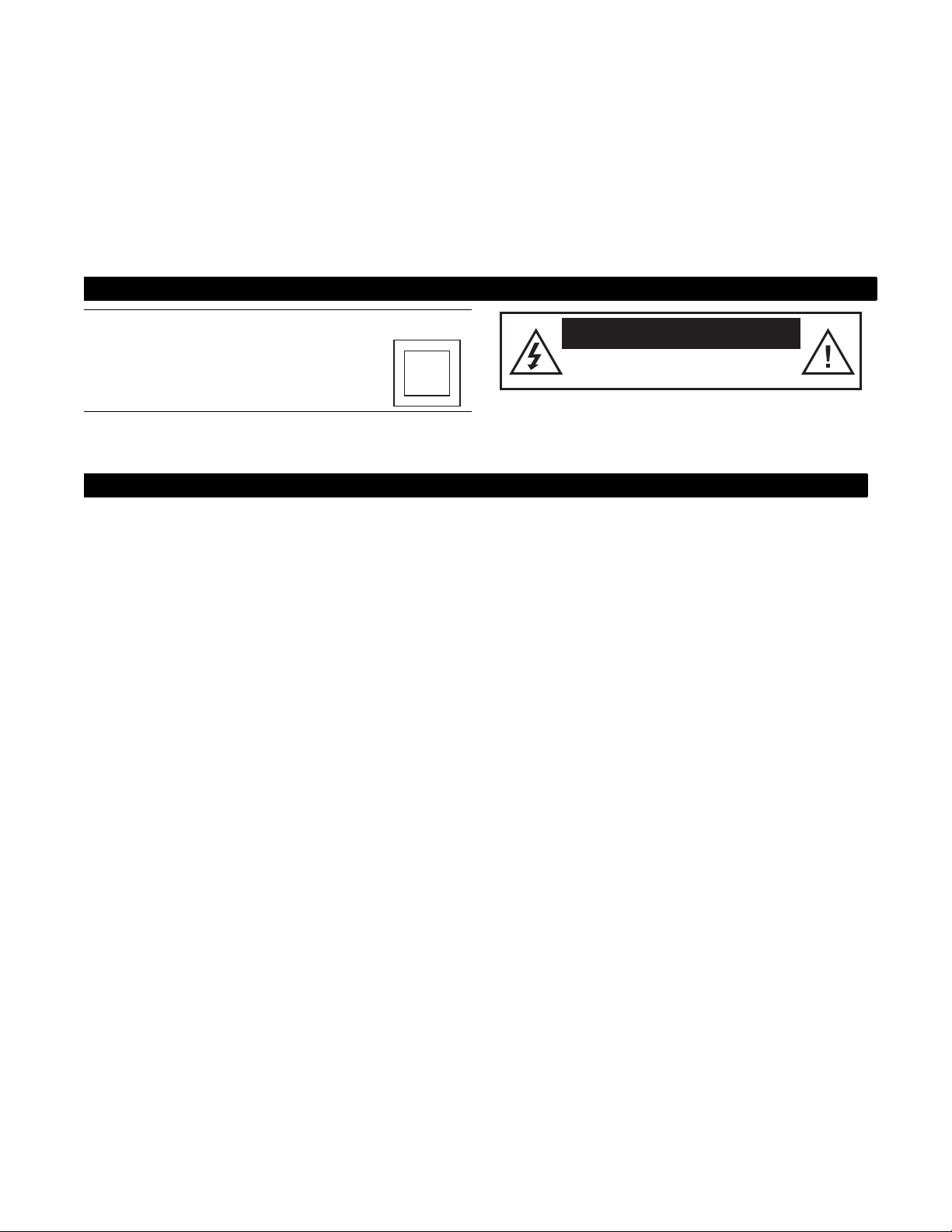
THESE CAUTIONS AND SYMBOLS APPEAR ON THE BACK OF THE RECEIVER
WARNING or CAUTION
Double insulated systems are protected
by additional board clearances and
creepage, so that the unit will not be a
safety hazard to the end-user.
IMPORTANT SAFETY INSTRUCTIONS
1. Read these instructions.
2. Keep these instructions.
3. Heed all warnings.
4. Follow all instructions.
5. Do not use this apparatus near water.
6. Clean only with dry cloth.
7. Do not block any ventilation openings. Install in
accordance with the manufacturer’s instructions.
8. Do not install near any heat sources such as
radiators, heat registers, stoves, or other apparatus
(including amplifiers) that produce heat.
9. Do not defeat the safety purpose of the polarized or
grounding-type plug. A polarized plug has two
blades with one wider than the other. A grounding
type plug has two blades and a third grounding
prong. The wide blade or the third prong is
provided for your safety. If the provided plug does
not fit into your outlet, consult an electrician for
replacement of the obsolete outlet.
CAUTION
RISK OF ELECTRICAL SHOCK
DO NOT OPEN
10. Protect the power cord from being walked on or
pinched particularly at plugs, convenience
receptacles, and the point where they exit from the
apparatus.
11. Only use attachments/accessories specified by the
manufacturer.
12. Unplug this apparatus during lightning storms or
when unused for long periods of time.
13. Refer all servicing to qualified service personnel.
Servicing is required when the apparatus has been
damaged in any way, such as power-supply cord or
plug is damaged, liquid has been spilled or objects
have fallen into the apparatus, the apparatus has
been exposed to rain or moisture, does not operate
normally, or has been dropped.
iii
Page 4

INSTALLATION
Ground
clamp
Electric
service
equipment
Ground
clamps
Power service
grounding electrode
Grounding
conductor
Coaxial cable
Grounding block
Coaxial cable
Polarization – This DIRECTV® Receiver is equipped with a plug that will
fit into the power outlet only one way. Do not modify the plug defeating this
feature. If the plug does not fit, contact your electrician to replace your
outlet. To prevent electric shock, do not use this plug with an extension cord
or outlet unless you can fully insert the blades without blade exposure
Power Sources – Operate this DIRECTV Receiver only from the type of
power source indicated on the marking label. If you are not sure of the type
of power supply to your home, consult your dealer or local power company.
Power-Cord Protection – Protect the power cord from being walked on
or pinched particularly at plugs, convenience receptacles, and the point
where they exit from the apparatus.
Overloading – Do not overload wall outlets, extension cords, or integral
convenience receptacles as this can result in a risk of fire or electrical shock.
Ventilation – Slots and openings in the cabinet are provided for ventilation
to ensure reliable operation of the product and to protect it from overheating.
Do not block any ventilation openings. Install in accordance with the
manufacturer’s instructions.
The openings should never be blocked by placing the product on a bed, sofa,
rug, or similar surface. This product should not be placed in a built-in
installation such as a bookcase or rack unless proper ventilation is provided
and the manufacturer’s instructions have been adhered to.
For electrical safety, power line operated equipment or accessories
connected to this unit should bear the UL listing mark and should not be
modified so as to defeat the safety features. This will help avoid any
potential hazard from electrical shock or fire. If in doubt, contact
qualified service personnel.
Heat–Do not install near any heat sources such as radiators, heat registers,
stoves, or other apparatus (including amplifiers) that produce heat.
Accessories – To avoid personal injury or damage to the DIRECTV
Receiver, do not place the DIRECTV Receiver on any unstable cart, stand,
table, or bracket. Any mounting of the product should follow the
manufacturer’s instructions.
Attachments – Do not use attachments unless recommended by
DIRECTV as they may cause hazards.
Satellite Dish Antenna Grounding – The outdoor satellite dish antenna
used to receive satellite signals and the cable used to connect the satellite
dish antenna to the indoor receiving unit are required to comply with local
installation codes and the appropriate sections of the National Electric Code
(NEC) and in particular Article 810-15, which covers proper installation and
grounding of television receiving equipment, as well as to Article 820-33,
which specifies that the satellite dish antenna cable ground shall be
connected to the grounding system of the building as close to the point of
cable entry as practical. These codes require proper grounding of the metal
structure of the outdoor satellite dish antenna and grounding of the
connecting cable at a point where it enters the house (or other building). If
you are having a professional installer perform the installation, the installer
must observe installation codes. This manual contains instructions on how to
make the installation in compliance with the NEC. If additional local
installation codes apply, contact local inspection authorities.
Example of Antenna Grounding according to the National
Electrical Code instructions contained in “Radio and Television
Equipment”.
Note: The DIRECTV Receiver must be grounded through the satellite/
local antenna cable before plugging into the telephone jack, and it must
remain grounded thereafter.
Water and Moisture – WARNING! To reduce the risk of fire or electric
shock, do not expose this product to rain or moisture.
Lightning – For added protection for this product during a lightning storm,
or when it is left unattended and unused for long periods of time, unplug it
from the wall outlet, disconnect the antenna and cable system, and
disconnect it from the telephone line. This will prevent damage to the
product due to lightning and power-line surges.
Television Antenna Information – Installing an outdoor antenna can be
hazardous and should be left to a professional antenna installer. Do not
locate the outside antenna system in the vicinity of overhead power lines or
other electric light or power circuits, or where it can fall into such power
lines or circuits. When installing an outside antenna system, take extreme
care to keep from touching such power lines or circuits, as contact with them
might be fatal. If an outside antenna is connected to the DIRECTV Receiver,
be sure the antenna system is grounded so as to provide some protection
against voltage surges and built-up static charges. This DIRECTV Receiver
is equipped with a plug that will fit into the power outlet only one way. Do
not modify the plug defeating this feature. If the plug does not fit, contact
your electrician to replace your outlet. To prevent electric shock, do not use
this plug with an extension cord or outlet unless you can fully insert the
blades without blade exposure. Section 810 of the NEC, NFPA No. 70 1987,
provides information with respect to proper grounding of the mast and
supporting structure, grounding of the lead-in wire to an antenna discharge
unit, size of the grounding conductors, location of antenna discharge unit,
connection to grounding electrodes, and requirements for the grounding
electrode.
Power Lines – Extreme care must be taken when installing and adjusting
or maintaining the outdoor antenna and connecting cable, especially in the
vicinity of overhead power lines, electric lights, or power circuits. When
installing the outdoor antenna or cable, extreme care should be taken to keep
from touching or approaching such power lines or circuits, as contact with
them might be fatal.
Cleaning – Unplug this receiver from the wall outlet before cleaning. Do
not use liquid or aerosol cleaners. Use only a damp cloth for cleaning.
Object and Liquid Entry – Never push objects of any kind into this
DIRECTV Receiver through openings as they may touch dangerous voltages
or “short out” parts that could result in a fire or electric shock. Never spill
liquid of any kind on the receiver. No objects filled with liquids, such as
vases, shall be placed on the apparatus.
iv
Page 5

SERVICE
Servicing–Do not attempt to service this DIRECTV® Receiver yourself as
opening or removing covers may expose you to dangerous voltage or other
hazards. There are no user serviceable parts inside. Refer all servicing to
qualified service personnel.
Conditions Requiring Service–Unplug the DIRECTV Receiver from
the wall outlet and refer servicing to qualified personnel under the following
conditions:
• When the power supply cord or plug has been damaged.
• If liquid has been spilled on, or objects have fallen into, the DIRECTV
Receiver or it has been exposed to water.
• If the DIRECTV Receiver does not operate normally by following the
operating instructions. Adjust only those controls that are covered by
the operating instructions. Other adjustments may result in damage and
will often require extensive work by a qualified technician to restore the
DIRECTV Receiver to its normal operation.
• If the DIRECTV Receiver has been dropped or the cabinet has been
damaged.
• When the DIRECTV Receiver exhibits a distinct change in
performance.
Replacement Parts–When replacement parts are required, have the
technician verify that the replacements being used have the same safety
characteristics as the original parts. Use of replacement parts specified by the
manufacturer can prevent fire, electric shock, or other hazards.
Safety Check–Upon completion of any service or repairs to this
DIRECTV Receiver, ask the service technician to perform safety checks
recommended by the manufacturer to determine that the DIRECTV Receiver
is in safe operating condition.
Multi-satellite capability–Multi-satellite capable if used with a
DIRECTV Multi-Satellite Dish Antenna, not included.
Automatic upgrades–Your DIRECTV Receiver is able to receive
upgrades or modifications to some of its features and functions. These
modifications will occur automatically, usually at times when the receiver
would likely be turned off. If your receiver is on when an upgrade or
modification is sent, you may experience a disruption in reception for a
minute or two. Your reception should return to normal after the modification
is complete. Your receiver must be plugged in to receive any upgrades. Do
not unplug you receiver while an upgrade is in progress. Please consult the
Upgrade menu to find a schedule of upgrades or modifications planned by
DIRECTV.
Local channel availability–With this receiver (HAH-SA, HBH-SA,
SD-HBH) and the proper satellite dish antenna, you may be able to subscribe
to local channels from DIRECTV in certain areas. Additional equipment
may be required in some markets. Check with your retailer or visit
DIRECTV.com for information on availability of local channels from
DIRECTV in your area.
v
Page 6

Federal Communications Commission (FCC) Regulatory Information
Declaration of Conformity– Standards to which Conformity is declared: FCC Part 15
This device complies with Part 15 of the FCC Rules. Operation is subject to the following two conditions: (1) this device may not cause harmful
interference, and (2) this device must accept any interference received, including interference that may cause undesired operation.
• Responsible Party’s Name: Hughes Network Systems, Inc.
Address: 11717 Exploration Lane, Germantown, MD 20876
Telephone: 1-800-274-8995
• Trade Name: Hughes
• Type of Equipment: Satellite Receiver
• Model Numbers: HAH-SA, HBH-SA, SD-HBH, HRMC-11, HRMC-12, HRMC-13
Federal Communications Commission (FCC)–This equipment complies with both Part 15 and Part 68 of the FCC rules
Part 15 Compliance–This equipment has been tested and found to comply with the limits for a Class B digital device, pursuant to Part 15 of the FCC rules.
These limits are designed to provide reasonable protection against harmful interference in a residential installation. This equipment generates, uses, and can
radiate radio frequency energy and, if not installed and used in accordance with the instructions, may cause harmful interference to radio communications.
However there is no guarantee that interference will not occur in a particular installation. If this equipment does cause harmful interference to radio or
television reception, which can be determined by removing and applying power to the equipment, the user is encouraged to try to correct the interference by
one or more of the following measures:
• Reorient or relocate the receiving satellite dish antenna.
• Increase the separation between the equipment and the DIRECTV
• Connect the equipment into an outlet on a circuit different from that to which the DIRECTV Receiver is connected.
• Consult the dealer or an experienced radio/TV technician for help.
The user may find the following booklet, prepared by the Federal Communications Commission, helpful: “How to Identify and Resolve Radio and TV
Interference Problems.” This booklet is available from the U.S. Government Printing Office, Washington, DC.
To meet FCC requirement, only peripherals (computer input/output devices, terminals, printers, etc.) certified to comply with Class B limits may be attached
to this device. Operation with noncertified peripherals is likely to result in interference to radio and TV reception.
To meet FCC requirements, shielded cables are required to connect the device to a personal computer, peripheral, or other Class B certified device.
Part 68 Compliance –This equipment complies with Part 68 of the FCC rules and requirements adopted by the ACTA. On the rear panel of this equipment
is a label that contains, among other information, a product identifier in the format US:5L4DT00B3003670. If requested, this information must be provided to
the Telephone Company.
A plug and jack used to connect this equipment to the premises wiring and telephone network must comply with the applicable FCC Part 68 rules and
requirements adopted by the ACTA. A compliant telephone cord and modular plug is provided with this product. It is designed to be connected to a compatible
modular jack that is also compliant. See installation instructions for details.
The REN is used to determine the number of devices that may be connected to a telephone line. Excessive RENs on the telephone line may result in the
devices not ringing in response to an incoming call. In most, but not all areas, the sum of RENs should not exceed five (5.0). To be certain of the number of
devices that may be connected to the line, as determined by the total RENs, contact the local Telephone Company. For products approved after July 23, 2001,
the REN for this product is part of the product identifier that has the format US:5L4DT00B3003670. The digits represented by the ## are the REN without the
decimal point (e.g., 03 is a REN of 0.3). For earlier products, the REN is separately shown on the label.
If the DIRECTV Receiver (Model Numbers: HAH-SA, HBH-SA, SD-HBH) causes harm to the telephone network, the Telephone Company will notify you in
advance that temporary discontinuance of service may be required. But if advance notice isn’t practical, the Telephone Company will notify the customer as
soon as possible. Also, you will be advised of your right to file a complaint with the FCC if you believe it is necessary.
The Telephone Company may make changes in its facilities, equipment, operations, or procedures that could affect the operation of the equipment. If this
happens, the Telephone Company will provide advance notice in order for you to make the necessary modifications to maintain uninterrupted service.
If trouble is experienced with the DIRECTV Receiver (Model Numbers: HAH-SA, HBH-SA, SD-HBH) equipment, for repair or warranty information, please
contact
Hughes Customer Care Center
Germantown, MD 20876
Telephone Number: 1-800-274-8995
http://www.hns.com
email: hughestv@hns.com
If the equipment is causing harm to the telephone network, the Telephone Company may request that you disconnect the equipment until the problem is
resolved.
Hughes Network Systems must make any necessary repairs to the modem portion of this equipment in order to maintain valid FCC registration. Do not
attempt to repair or service your modem. Return it to Hughes Network Systems.
No repairs can be made by customers. All repairs must be done by Hughes Network Systems Authorized Service Centers (ASCs). This equipment cannot be
used on public coin service provided by the Telephone Company. Connection to Party Line Service is subject to state tariffs. Contact the state public utility
commission, public service commission or corporate commission for information.
®
Receiver.
vi
Page 7

Contents
Getting Started . . . . . . . . . . . . . . . . . . . . . . . 1
Setup overview . . . . . . . . . . . . . . . . . . . . . . . . . . . . 1
Attach the satellite antenna cable . . . . . . . . . . . . 2
Connect your TV. . . . . . . . . . . . . . . . . . . . . . . . .3
Determine antenna angles . . . . . . . . . . . . . . . . . .4
Testing your system . . . . . . . . . . . . . . . . . . . . . .5
To perform the Transponder test: . . . . . . . . . . 5
Adding system components . . . . . . . . . . . . . 7
Connecting additional system components. . . . . . . 7
Connecting a terrestrial antenna/CATV . . . . . . . 7
Connecting a VCR . . . . . . . . . . . . . . . . . . . . . . .7
Connect the VCR Control Cable. . . . . . . . . . .8
Test the VCR (Record/Stop) . . . . . . . . . . . . . .8
Connecting a home entertainment system. . . . . . 9
Using the remote control . . . . . . . . . . . . . . 11
Remote control functions . . . . . . . . . . . . . . . . . . . 13
Programming the remote control. . . . . . . . . . . . . .14
Code Entry. . . . . . . . . . . . . . . . . . . . . . . . . . . . .14
Code Scanning. . . . . . . . . . . . . . . . . . . . . . . . . .15
Changing the Remote ID. . . . . . . . . . . . . . . . . . 15
Installing remote control batteries. . . . . . . . . . . 15
Using program guides. . . . . . . . . . . . . . . . . 17
Selecting a program guide style . . . . . . . . . . . . . .17
Grid guide . . . . . . . . . . . . . . . . . . . . . . . . . . . . .17
Logo guide. . . . . . . . . . . . . . . . . . . . . . . . . . . . . 18
Program guide and menu features. . . . . . . . . . . . . 19
Using the OneLine
Using TurboTune
Setting TurboTune channels . . . . . . . . . . . . . . . 20
Renaming TurboTune groups . . . . . . . . . . . . . .21
Using DIRECTV INTERACTIVE™
powered by Wink Communications
Setting guide preferences . . . . . . . . . . . . . . . . . . .22
™
Guide . . . . . . . . . . . . . . . . . . 20
™
. . . . . . . . . . . . . . . . . . . . . . . .20
®
. . . . . . . . .21
Using the menus . . . . . . . . . . . . . . . . . . . . . 23
Onscreen menu icons . . . . . . . . . . . . . . . . . . . . . 24
Purchasing pay per view (PPV) events . . . . . . . . .24
Cancelling purchases. . . . . . . . . . . . . . . . . . . . .24
Reviewing past purchases . . . . . . . . . . . . . . . . .24
Listing unviewed purchases . . . . . . . . . . . . . . . 25
Adjusting audio settings . . . . . . . . . . . . . . . . . . . . 25
Setting default and alternate audio . . . . . . . . . . 25
Using TruSurround . . . . . . . . . . . . . . . . . . . . . 26
Using Dolby Digital audio . . . . . . . . . . . . . . . . 26
Adjusting video settings . . . . . . . . . . . . . . . . . . . . 26
Using WatchWizard™ . . . . . . . . . . . . . . . . . . . . . 27
Using the Channels search . . . . . . . . . . . . . . 28
Using the Program Director . . . . . . . . . . . . . . . . . 28
Scheduling or editing an event . . . . . . . . . . . . . 29
Adjusting system settings . . . . . . . . . . . . . . . . . . . 30
Set output channel. . . . . . . . . . . . . . . . . . . . . . . 30
Input key enable/disable . . . . . . . . . . . . . . . . . . 30
Select menu language . . . . . . . . . . . . . . . . . . . . 30
Caller ID enable/disable . . . . . . . . . . . . . . . . . . 30
Restore factory default settings. . . . . . . . . . . . . 30
Viewing Mail . . . . . . . . . . . . . . . . . . . . . . . . . . . . 31
Using Caller ID. . . . . . . . . . . . . . . . . . . . . . . . . . . 31
Setting favorites and filters . . . . . . . . . . . . .33
Using favorite channel lists. . . . . . . . . . . . . . . . . . 33
Creating a channel list. . . . . . . . . . . . . . . . . . . . 33
Renaming a channel list:. . . . . . . . . . . . . . . . . . 34
Creating an Auto Set list. . . . . . . . . . . . . . . . . . 34
Adding and removing channels . . . . . . . . . . . . 34
Finding new channels . . . . . . . . . . . . . . . . . . . . 35
Filtering the program guide . . . . . . . . . . . . . . . . . 35
Using Theme Filters . . . . . . . . . . . . . . . . . . . . . 35
Selecting guide times . . . . . . . . . . . . . . . . . . . . 36
Using access controls . . . . . . . . . . . . . . . . . .37
Locking & unlocking the system . . . . . . . . . . . . . 37
How to lock the system. . . . . . . . . . . . . . . . . . . 37
Unlocking the system . . . . . . . . . . . . . . . . . . . . 37
Setting ratings limits . . . . . . . . . . . . . . . . . . . . . 37
Setting spending and time limits. . . . . . . . . . . . 38
Questions & Answers . . . . . . . . . . . . . . . . . .39
Manufacturers device control codes . . . . . .41
Contents
vii
Page 8

viii
Contents
Page 9

This chapter explains how to:
Getting Started 1
You may connect a second
DIRECTV Receiver to the unused
LNB output. These instructions
also apply to an additional
receiver.
• Connect the DIRECTV® Satellite Dish Antenna to your DIRECTV
Receiver (this page).
• Connect your DIRECTV Receiver to your TV (see page 3).
• Find antenna azimuth and elevation settings for your location (see page 4).
• Test the DIRECTV System operation (see page 5).
How to use this manual
This manual uses these typographical conventions to help clarify instructions:
Text Example Description
Click Cancel.
Highlight the Messages
button.
Press the INFO button.
Connect a pair of A/V
cables to the
AUDIO IN jack.
Highlight the Options tab.
Display the MAIN MENU.
On-screen command buttons that execute an action.
Selections or other option buttons within a menu
pane.
Remote control buttons, or receiver front panel.
Names of equipment cable connections on
equipment.
Menu tab names.
Menu and pane names, names of pop-up and
sub-menu panes.
Setup overview At this point, you should have:
• Mounted the DIRECTV Satellite Antenna and pointed it in the general
direction of the satellite.
• Grounded the antenna as described in your antenna installation instructions.
• Attached RG-6 coaxial cable(s) to the antenna LNB connector(s).
• Routed the other end of the antenna cable to the back of your DIRECTV
Receiver.
• Placed the DIRECTV Receiver accessible to a telephone modular jack.
• Inserted the access card into your DIRECTV Receiver.
Ensure that you have completed these procedures, then continue to the next
page to begin installing the DIRECTV Receiver.
Getting Started
1
Page 10
Attach the satellite
antenna cable
You can configure your system several ways, depending on what additional
components (such as a VCR, DVD player, or A/V receiver) you select. For now,
however, use the simplest configuration to check your antenna and cabling.
®
• Ensure that the DIRECTV
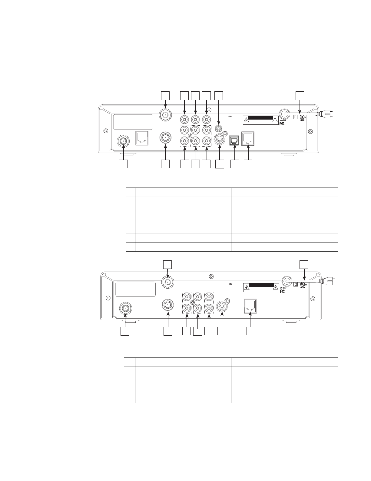
• Attach the RG-6 coaxial antenna cable to the
Receiver is not plugged into an electrical outlet.
SATELLITE IN connector on
the back of the DIRECTV Receiver. Refer to the appropriate figure below.
HAH-SA
SATELLITE IN
DATA PORT
1
1 SATELLITE IN connector 8 Pb component output jack
2 OUT TO TV connector 9 Y component output jack
3 TV ANTENNA/CABLE IN connector 10 VCR CONTROL cable jack
4 AUDIO OUTPUT (R) jacks 11 S-VIDEO jack
5 AUDIO OUTPUT (L) jacks 12 DIGITAL AUDIO OUTPUT optical jack
6 VIDEO OUTPUT jacks 13 TELEPHONE JACK
7 Pr component output jack 14 AC POWER CORD
HBH-SA / SD-HBH
Model No. HAH-SA
Tested to Comply
With FCC Standards
FOR HOME OR OFFICE USE
14
AUDIO/VIDEO
APPARATUS
52BN
E212442
3
TV ANT/CABLE IN
(NOT SATELLITE)
OUT TO TV
2
PR PB
RL
AUDIO
4
87 9
Y
5
10
TruSurround, SRS and symbol
are trademarks of SRS Labs, Inc.
S-VIDEO
VIDEO
6
11
DIGITAL
AUDIO OUT
12
CAUTION
RISK OF ELECTRICAL SHOCK
DO NOT OPEN
120V-1A, 60Hz
This device complies with Part 15 of the FCC rules. Operation is
subject to the following two conditions: (1) This device may not
cause harmful interference, and (2) This device must accept any
interference received, including interference that may cause
undesired operation.
Complies with 47 CFR Part 68.
US: 5L4DT00B3003670
This product and service are covered by one or more U.S. patents.
Other U.S. and foreign patents pending. See Users Manual for details.
Manufactured under license from Dolby Laboratories. Dolby and the
double-D symbol are trademarks of Dolby Laboratories.
PHONE JACK
Manufactured by Hughes Network Systems
13
Table 1: Rear panel connections - DIRECTV Receiver model HAH-SA
3
9
TruSurround, SRS and symbol
SATELLITE IN
1
TV ANT/CABLE IN
(NOT SATELLITE)
OUT TO TV
2
RL
AUDIO
4
5
are trademarks of SRS Labs, Inc.
VIDEO S-VIDEO
6
7
CAUTION
RISK OF ELECTRICAL SHOCK
DO NOT OPEN
120V-1A, 60Hz
This device complies with Part 15 of the FCC rules. Operation is
subject to the following two conditions: (1) This device may not
cause harmful interference, and (2) This device must accept any
interference received, including interference that may cause
undesired operation.
Complies with 47 CFR Part 68.
US: 5L4DT00B3003670
This product and service are covered by one or more U.S. patents.
Other U.S. and foreign patents pending. See Users Manual for details.
PHONE JACK
Manufactured by Hughes Network Systems
8
Model No.
Tested to Comply
With FCC Standards
FOR HOME OR OFFICE USE
Table 2: Rear panel connections - DIRECTV Receiver model HBH-SA/SD-HBH
1 SATELLITE IN connector 6 VIDEO OUTPUT jacks
2 OUT TO TV connector 7 S-VIDEO jack
3 TV ANTENNA/CABLE IN connector 8 TELEPHONE jack
4 AUDIO OUTPUT (R) jack 9 AC POWER CORD
5 AUDIO OUTPUT (L) jack
AUDIO/VIDEO
APPARATUS
52BN
E212442
2
Getting Started
Page 11

Connect your TV
Depending on your TV, you can connect it to the receiver in one of four ways:
• Component (Y,Pb,Pr,-HAH-SA only) video cable (best picture quality) or
• S-Video cable (excellent picture quality) or
• Video cable (very good picture quality) or
• Coaxial cable (good picture quality)
You will also want to use a pair of audio cables (L/R) to provide stereo sound.
If your TV does not have standard A/V jacks, you will hear monophonic audio.
This is acceptable for the procedures described in the next section.
®
To connect your TV to the DIRECTV
Receiver:
1. Select the appropriate connection:
If your TV has component video jacks –
• Use a component video cable (not supplied) or supplied A/V cable to
connect the DIRECTV Receiver’s
Y, PB, and PR output to the
corresponding TV input jacks.
• Use supplied A/V cable to connect the DIRECTV Receiver’s
(
L/R) jacks to the TV’s AUDIO IN jacks.
AUDIO
If your TV has an S-Video jack –
• Use an S-Video cable (not supplied) to connect the DIRECTV
Receiver’s
• Use supplied A/V cable to connect the DIRECTV Receiver’s
S-VIDEO jack to the TV’s S-VIDEO input jack.
AUDIO
(L/R) jacks to the TV’s AUDIO IN jacks.
The data port (HAH-SA only) is used
for diagnostic and aftermarket
service. Professional installations
using the data port must utilize a
good quality shielded cable to ensure
FCC compliance.
If your TV has RCA-type A/V connectors –
• Use the supplied A/V cable to connect the DIRECTV Receiver’s
AUDIO and VIDEO jacks to the TV’s A/V IN jacks.
• If your TV has only one
L
jack to the TV AUDIO IN jack.
AUDIO IN jack, connect the receiver’s AUDIO
If your TV only has an RF (coaxial) connector –
• Connect the DIRECTV Receiver’s
VHF/UHF IN or RF IN jack.
OUT TO TV connector to the TV’s
2. Connect one end of the telephone line cord provided into the DIRECTV
Receiver’s
PHONE JACK.
3. Connect the other end into a modular telephone outlet.
4. Plug the TV into an electrical outlet.
5. Plug the DIRECTV Receiver power cord into an electrical outlet. If the
front panel Power indicator does not illuminate, press the
POWER button.
Getting Started
3
Page 12
Determine antenna
SELECT
MENU
POWER
angles
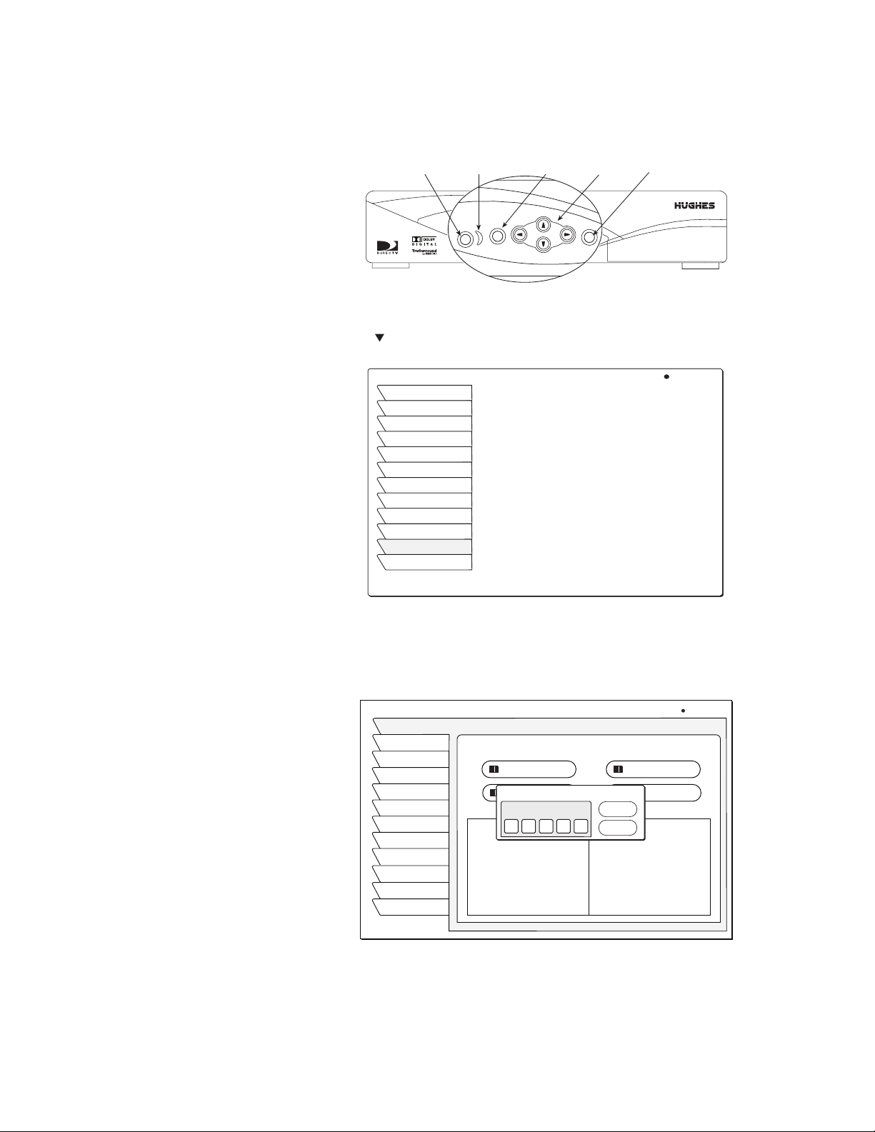
This section explains how to determine the proper antenna position, expressed
in degrees of azimuth (horizontal) and elevation (vertical). Use the receiver front
panel controls shown below to complete this procedure.
Power
On/Standby
1. Press the front panel
Power
Main Menu
Indicator
MENU
POWER
MENU button to display the MAIN MENU below.
2. Use the button to highlight the
MAIN MENU Tue, Nov 6 4:20PM
Program Guide
Guide Options
Audio & Video
Caller ID
Program Director
WatchWizard
Interactive
Purchases
Lock & Limits
View Mail
System Setup
Watch TV
Button
Buttons
SELECT
System Setup tab.
Direction
SELECT
Button
“Tilt angle” also appears if you
have selected an Oval Antenna
from the Dish Type menu.
3. Press the front panel
SELECT button.
4. The INSTALL menu helps you to determine the correct antenna position
using your 5-digit ZIP code. Enter your ZIP code and press OK.
INSTALLATION
Install
Signal
Info
Features
VCR
Prefs
Remote
Test
New Card
Upgrade
Watch TV
Main Menu
Dish Pointing
Dish Type
Autoconfig
ZIP Code
2 0 9 0 2
Dish Type:
Round Dish
Networks:
0, 3
Switch Type:
Simple
LNB: Unstacked
ZIP Code Entry
Wed, Oct 2 12:16PM
Alignment Mode
ZIP Code
Lat/Longitude
OK
Cancel
ZIP Code :
Latitude :
Longitude :
Elevation : 0
Azimuth : 0
The correct azimuth and elevation angles will appear with onscreen instructions
for using these values to properly align your dish antenna.
5. Highlight and
SELECT the Autoconfig menu button to automatically set
your receiver to work with these antenna values.
4
Getting Started
Page 13
Testing your system
When you have aligned your dish antenna to the azimuth and elevation angles
shown on the
Install pane, highlight the Signal tab. Signal quality is indicated
by a scale at the bottom of the pane and with an audible indication. The
frequency and tempo of the tone increase with signal strength.
To perform the Transponder
test:
Use this procedure to test the signal strength from the satellite transponder:
1. Select the
System Setup tab from the MAIN MENU
2. Highlight the Signal tab to display the SIGNAL STRENGTH menu pane.
3. Highlight the Tes t menu button as shown in the figure below.
4. Press
5. Press
SIGNAL STRENGTH
Install
Signal
Info
Features
VCR
Prefs
Remote
Test
New card
Upgrade
Watch TV
Main Menu
Xponder
29
Cursor to the right to activate the
Signal Strength
Source
Satellite 101
Status: Signal Locked
Current: 95 Highest: 98
signal monitor.
SELECT to display the Transponder Test menu (see figure below).
SELECT to begin the test on the highlighted selection.
Thu, Oct 3 1:14 PM
)
(A)
Xponder
Test
Note: Xponder and Source selections displayed may vary from those shown.
SIGNAL STRENGTH
Install
Signal
Info
Features
VCR
Prefs
Remote
SIGNAL STRENGTH
Test
Install
New Card
Signal
Upgrade
Info
Watch TV
Features
Main Menu
VCR
Prefs
Remote
Test
New Card
Upgrade
Watch TV
Main Menu
Xponder
18
Xponder
18
916
1724
2532
Signal Strength
Source
TransponderTest
Satellite 101
Satellite 101 (A)
Satellite 119 (B)
Satellite 110 (C)
Status: Signal Locked
Current: 95 Highest: 95
Satellite 101 (A) Signal Strength
95
18
94
93
94
Cancel
Signal Strength
Source
Satellite 101)(A)
95
95
93
94
93
95
95
94
)
(A)
: 5317.6
:0.0.0.75
:OK
:OK
94
94
93
95
95
94
93
93
Thu, Oct 3 1:14 PM
Xponder
Test
Thu, Oct 3 1:14 PM
Xponder
Stop
93
94
95
94
94
92
93
93
92
92
94
94
Getting Started
5
Page 14

An occasional “0” indication may be
considered normal.
Results should generally resemble those in the figure, but the actual values will
vary somewhat from those shown in the figure depending on your geographic
location and specific installation. However, if your results are very different
from these examples (i.e, rows of zeros or single-digit numbers) or you receive
no signal indication:
• Highlight the
Install tab on the INSTALLATION menu. Verify your settings.
• Re-enter your ZIP code if necessary to verify you have used the correct
antenna pointing parameters for your location.
• Check your cable connections.
®
• Ensure the DIRECTV
Receiver is connected to a modular telephone jack.
Once you have successfully obtained a signal and your test results resemble
those shown in the figures, call DIRECTV (or your subscription service
provider) to activate service if you have not already done so.
6
Getting Started
Page 15

Adding system components 2
You can configure your DIRECTV® Receiver several ways depending on the
additional audio/video components you want to use.
This chapter explains how to:
• Connect a terrestrial (broadcast) TV antenna (this page).
• Connect and set-up a VCR (see page 8).
• Integrate a DIRECTV Receiver into your audio or A/V system (see page 9).
Connecting
additional system
components
Connecting a terrestrial
antenna/CATV
Connecting a VCR
At this point, you should have:
Verified that your system is operating properly.
Connected your DIRECTV Receiver to your TV.
Unplugged all components from electrical outlets.
You can connect a terrestrial (broadcast) TV antenna or CATV to your
DIRECTV Receiver by connecting it to the DIRECTV Receiver’s
ANT/CABLE IN jack (see figures on page 2). The remote control INPUT button
allows you to switch between DIRECTV
terrestrial antenna or CATV.
Follow these instructions to connect your TV and VCR to the DIRECTV®
Receiver. Connect the satellite antenna RG-6 coaxial cable to the DIRECTV
Receiver’s
1. Depending on your VCR, select the appropriate connection to the
DIRECTV Receiver:
If your VCR has A/V connectors –
SATELLITE IN jack (see figures on page 2).
• Connect the DIRECTV Receiver’s
VCR’s
• If your VCR has only one
(mono)
A/V IN jacks.
AUDIO L jack to the VCR’s AUDIO IN jack.
®
programming and input from the
AUDIO and VIDEO jacks to the
AUDIO IN jack, connect the receiver’s lower
TV
If your VCR only has an RF (coaxial) connector–
• Connect the DIRECTV Receiver’s
VHF/UHF IN or RF IN jack.
2. Depending on your TV and VCR, select the appropriate method to the
connect the VCR to the TV:
If your TV and VCR have A/V connectors –
• Connect the DIRECTV Receiver’s
corresponding
If your TV or VCR only has an RF (coaxial) jack –
• Connect the VCR’s
3. Plug the TV, VCR, and DIRECTV Receiver power cords into an electrical
outlet.
A/V IN jacks on your TV.
VHF/UHF OUT jack to the TV’s VHF/UHF IN jack.
OUT TO TV connector to the VCR’s
AUDIO and VIDEO jacks to the
Adding system components
7
Page 16
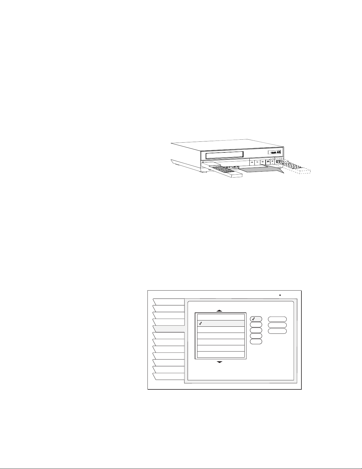
Connect the VCR Control
Cable
(Model HAH-SA only) The DIRECTV® Receiver can control your VCR for
unattended recording, using the VCR Control Cable provided.
1. Plug the VCR control cable into the rear panel
VCR CONTROL jack.
2. Temporarily position the other end over the VCR’s remote control sensor
(normally a small dark plastic window on the VCR front panel).
The remote control sensor may be labeled or identified in your VCR manual.
If it is not identified, scan the front of the VCR with your VCR remote control:
3. Hold the VCR remote control about ½-inch (1.3 cm) from the front left side.
4. Slowly move the remote control to the right as shown in the figure.
5. Repeatedly press the VCR remote control’s power key on and off.
Scanning for the VCR remote control sensor
6. When your VCR responds to your pressing the remote control power, note
the position. Temporarily tape the IR emitter to the position you marked
until you verify that it works properly.
Test the VCR (Record/Stop)
This Record/Stop test verifies the specified brand and code controls your VCR.
1. Turn the VCR power on.
2. Insert a recordable videotape into the VCR.
3. Using the satellite receiver front panel buttons, (don’t use the remote
control)
4. Highlight and
SELECT the VCR tab from the SYSTEM SETUP menu.
SELECT your VCR brand as shown below.
VCR SETUP
Install
Signal
Info
Features
VCR
Prefs
Remote
Test
New Card
Upgrade
Watch TV
Main Menu
Brand TestCode
Aiwa
Akai
Audio Dynamics
Bell & Howell
Broksonic
Canon
Capehart
Select Code
Wed, Oct 30 11:53AM
Record
1
2
3
4
5
Stop
Clear
8
Adding system components
5.
SELECT the highlighted Code menu button.
6.
SELECT the Record menu button under the Tes t column.
7. Verify the VCR is recording.
8.
SELECT the Stop menu button.
Page 17

If either command does not function, try other codes listed for your VCR brand.
If you are unsuccessful after trying all available codes, recheck your VCR
Control Cable connections and IR emitter placement.
9. Remove the temporary mounting tape. Attach the emitter permanently using
the peel-and-stick backing. This will not interfere with normal VCR
operation.
Connecting a home
entertainment system
The A/V receiver must be
turned on in order to send the
video and video signal to your
TV.
You can integrate the DIRECTV® Receiver into your entertainment system to
take advantage of enhanced audio and video capability. Follow these
instructions to connect your DIRECTV Receiver.
• To connect the DIRECTV Receiver to your audio system, use A/V cables to
connect the satellite receiver to the audio receiver’s
AUDIO IN jacks.
• Dolby Digital - With the HAH-SA satellite receiver, you can enjoy
programs that contain a Dolby Digital sound track. We recommend that you
listen in surround sound for maximum enjoyment of these programs. You
can connect the stereo outputs of the HAH-SA to a receiver that contains a
Dolby Surround Pro Logic decoder. This will provide you with three audio
channels in the front and a mono surround channel.
• To take full advantage of Dolby Digital programming, connect the HAH-SA
digital audio output to an external 5.1-channel Dolby Digital decoder or
receiver. This provides you with three front channels, two independent
surround channels, and an LFE (or subwoofer) channel.
1. Connect the satellite antenna RG-6 coaxial cable to the DIRECTV
Receiver’s
2. Connect the DIRECTV Receiver’s
A/V jacks.
SATELLITE IN jack.
A/V jacks to the VCR and A/V receiver’s
3. AUX, optical connection, and digital output connections – If your audio
receiver has optical digital connectors, connect the appropriate type of cable
to the DIRECTV Receiver’s
DIGITAL AUDIO OUT for two-channel digital
stereo. If your A/V receiver is also capable of decoding Dolby Digital, use
this connection in order to listen in full 5.1-channel surround sound. Refer
to page 25 for additional audio information.
4. Connect the VCR’s
A/V OUT jacks to a pair of the A/V receiver’s A/V IN
jacks.
5. Connect the A/V receiver’s
MONITOR OUT jack to the TV’s VIDEO IN
jack.
6. Plug the components into an electrical outlet.
Note: If you have connected a VCR to your entertainment system in a
way that routes the satellite receiver’s signal to your VCR before it reaches
the TV, you may see a distorted picture if you try to record (or view in some
instances) a copy-protected program. A
banner identifies these programs.
Can’t Tape
Adding system components
symbol in the screen
9
Page 18

10
Adding system components
Page 19

Using the remote control 3
This chapter explains how to:
• Use the HRMC-11, HRMC-12, and HRMC-13 remote control functions.
(see page 13)
• Program the remote to work with other system components. (see page 14)
• Install and replace the remote control batteries. (see page 15)
Power
Turns satellite receiver power on/off (standby).
HRMC-13
MENU
POWER
VCR
GUIDE
1-LINE
SELECT
TURBO
SATAUX TV
INFO
Turns selected component power on/off.
Component controls
Selects the component that you want to control.
Buttons illuminate to indicate the component
that the remote control is set to operate.
Select
Press to select an on-screen option,
Press the arrows to move the screen highlight.
Directional arrow buttons
Moves the onscreen menu highlght or cursor.
Channel (CH) up/down
Moves to next or previous channel during viewing.
Display next program guide page (Grid guide only).
VOL CH
CLEAR
PREV
MUTE
CH
1 2 3
4
5
7
8
INPUT
0
6
9
Main menu
View the Main Menu
OneLine Guide
Press to view the
OneLine Guide.
TurboTune
View the TurboTune Guide
Clear
Cancel the on-screen function
and return to previous activity
Previous channel
Toggle between the current channel and
the last channel watched.
Numeric keypad
Reserved for future upgrade
Input
Change video input source
(CATV, terrestrial antenna, or other video device).
VCR control
Performs VCR control functions
Program guide
GUIDE
MENU
1-LINE
SELECT
TURBO
View the list of available programming
INFO
Information
View information about the
currently selected program
HRMC-13 Remote Control Function Quick Reference
Using the remote control
11
Page 20

.
PWR
VCRDVD AUX TV SAT
GUIDE
MENU FAV
INFO
VOL
PROG
1 2
4
7
INPUT
INPUT
REW
REW
REC
REC
SELECT
MUTE
DIRECTOR
SEARCH
5
8
PLAY
PLAY
STOP
STOP
TURBO1-LINE
CLEAR
PREV
CH
VIDEO
AUDIO
3
6
9
0
FF
FF
PAUSE
PAUSE
Power
Turns satellite receiver power on/off (standby).
Turns selected component power on/off.
SAT
Component controls
Selects the component that you want to control.
Buttons illuminate to indicate the component
that the remote control is set to operate.
Receiver control group
Most frequently used functions
are grouped together (see below).
Navigation PADDLE
Moves the oncsreen menu highlght or cursor.
Channel (CH) up/down
P
CH
Moves to next or previous channel during viewing.
A
G
Display next program guide page (Grid guide only).
E
Previous channel
Toggle between the current channel and
the last channel watched.
Director group
One-touch navigation to setup menus for audio, video,
program guide, and WatchWizard searches.
Numeric keypad
Reserved for future upgrade
Input
Change video input source
(CATV, terrestrial antenna, or other video device).
VCR control
Performs VCR control functions
Backlight (HRMC-12 only)
Turn on keypad backlight
Program guide
View the list of available programming
INFO
GUIDE
SELECT
TurboTune
TURBO1-LINE
CLEAR
View the TurboTune Guide
Favorites
View listings of your preferred programming
Clear
Cancel the on-screen function
and return to previous activity
Select
Press to select an on-screen option,
OneLine Guide
Press to view the
OneLine Guide.
Main menu
View the Main Menu
Information
View information
about the currently
selected program
MENU FAV
Press the arrows to move the screen highlight
HRMC-11 and HRMC-12 Remote Control Function Quick Reference
The DIRECTV® Receiver front panel buttons provide the basic controls needed
to access major DIRECTV System features. However, using the remote control
simplifies accessing the basic system functions, enhances your system’s
capabilities, and provides convenient shortcuts to extended features.
Additionally, most remote control buttons can also control other home
entertainment system components.
12
Using the remote control
Page 21

Remote control
functions
Use the directional paddle or directional arrow buttons to move up, down, left,
or right through the on-screen displays. This icon appears throughout this
manual to instruct you to use the paddle or directional arrow buttons to navigate
through on-screen menus and guides.
Pressing the paddle or directional arrow buttons left or right while watching a
program displays the Alternate Audio selection popup menu.
1-LINE
or
SELECT
GUIDE
INFO
CH
CLEAR
1-LINE
Press the
Press the
time (while a program title is highlighted) to display the
Press the
SELECT button to activate or choose a highlighted menu option.
GUIDE button to display the current program guide. Press it a second
Category Filter menu.
INFO button to display a brief description about the program you are
viewing. For more details, press it again to display the Information Banner. The
INFO button provides scheduling information (and pay per view purchase
information) about the program highlighted in the program guide.
See Chapter 4 – Using program guides, on page 17 for more information.
P
A
G
E
Use the
channel or scroll through a page of program guide selections
Press the
CHANNEL (CH) button to move up or down to the next available
CLEAR button to exit from any on-screen guide, remove banners, or
cancel an action.
Press the
onscreen, pressing the
1-LINE button to display the OneLine™ guide. When the OneLine is
1-LINE button again adds another line to the guide, up to
four lines (applies to HRMC-11 and HRMC-12 only). When the OneLine guide
appears, press the paddle or directional arrow buttons up or down to step to
the next higher- or lower-numbered channel.
TURBO
DIRECTOR
SEARCH
or
AUDIO
TURBO
INPUT
SAT
VIDEOPROG
Press the
TURBO button to display the TurboTune™ menu guide (HRMC-11
and HRMC-12 only).
INPUT button allows you to select programming from additional program
The
sources such as a DVD player, VCRs, or a terrestrial TV antenna signal.
Repeatedly press
INPUT to cycle through each available input source in your
system.
Press the
SAT component select button to control the DIRECTV
®
Receiver.
The other component select buttons indicate the devices they control. You can
program the
AUX button to control another digital device such as an audio CD
player.
DIRECTOR buttons provide convenient shortcuts to the Program Director,
The
WatchWiz ard
™, audio, and video adjustment menus (HRMC-11 and HRMC-12
only).
Using the remote control
13
Page 22

Programming the
remote control
You can operate your TV, VCR, SAT, AUX device, or DVD (HRMC-11 and
HRMC-12 only) devices using your remote control. Use the Code Entry or
Code Scanning method to program the remote control. Using the Code entry
method may be quicker, but you’ll need to know the correct manufacturer’s
control codes for each component you want to operate. Code scanning may be
more time-consuming, but you don’t need to know manufacturer’s control
codes.
1. Keep your remote control aimed at the device you want to control during
this process. The remote control will send out the “power” command for the
device being programmed.
2. Press and hold the device key (for example,
3. Press press the
MUTE key for two seconds.
TV)
4. Release both keys.
The device key should light and remain lit. If it doesn’t remain lit, repeat
steps 1 through 4 above.
5. Choose one of the programming methods described below:
Code Entry
Use the REMOTE pane under the System Setup menu tab to program your
HRMC-11, HRMC-12, or HRMC-13 remote control to operate your TV, VCR,
SAT, AUX device, or DVD (HRMC-11 and HRMC-12 only). The AUX menu
button can be used to control a CATV box or other type of device. Use the menu
buttons to choose the desired type of device and display a brand name menu list
from which you can select the manufacturer of your device.
REMOTE
Install
Signal
Info
Features
VCR
Prefs
Remote
Test
New Card
Upgrade
Watch TV
Main Menu
Remote Control Settings
Remote ID Unit 1
TV
AUX
VCR
DVD
Factory Defaults
1. Aim your remote control at the
TV you want to use.
2. Hold down the TV button.
3. Press the MUTE button for one
second.
4. Release both buttons together.
5. The TV button glows and
remains lit. If the button does not
001, 034, 038, 083, 199
Wed, Oct 30 11:53AM
Brand
A Mark
Akai
Amstrad
Anam
AOC
Audiovox
Blaupunkt
Highlight the device you want to
select. Press
SELECT
14
Using the remote control
Device codes appear in the menu pane for the brand selected. Step-by-step
onscreen help guides you through the procedure. Appendix B – Manufacturers
device control codes, on page 41 also provides a complete list of device codes.
Page 23

Code Scanning
To use the Code Scanning method:
P
A
CH
G
E
Changing the Remote ID
1. Repeatedly tap the top part of the
CHANNEL (CH) button.
2. Continue to step through the codes until the component turns off, indicating
you have found the correct component code. If you accidentally pass a code
that responds or realize you may not have been aiming the remote control at
the component, tap the lower part of the
CHANNEL (CH) button to step
backward through the codes.
3. Press the remote control
POWER button to verify the proper code by
turning the device on and off.
4. Press the device button (in this example,
TV) again to lock in the code.
If you are using multiple satellite receivers in the same room, you may want to
change the remote control ID to avoid interference or “cross talk.” The remote
control ID can be a number from “001” to “008”.
If you change remote IDs, set your remote control to that ID number first.
Use this procedure to set the remote control to use a different remote ID:
1. From the
MAIN MENU, highlight the System Setup menu tab. Press
SELECT.
2. Highlight
Remote menu tab to access Remote Control Settings.
3. Highlight the Remote ID menu button.
4. Press and hold the remote control SAT button.
5. Press and release the
6. Release the
SAT button. It should remain lit. If it does not, repeat steps 4-6.
MUTE button.
7. Enter desired number (001 to 008).
8. Press the
9. Point the remote control at the receiver. Press
SAT button to lock in the code.
SELECT.
Installing remote control
batteries
The number to the right of the highlighted Remote ID menu button will change
to the new code. Check that the ID has been successfully set by testing the
remote control to see that it controls that satellite receiver.
To install or replace the remote control batteries:
1. Locate the battery compartment on the back of the remote control.
2. Remove the battery compartment cover.
3. Insert two “AAA” size batteries as shown, observing the correct polarity.
4. Replace the battery compartment cover.
Using the remote control
15
Page 24

16
Using the remote control
Page 25

Using program guides 4
This chapter describes:
• The different program guide styles (this page).
• Common program guide and menu features (see page 19).
™
• How to use the OneLine
• How to set-up and use the TurboTune
• Using DIRECTV INTERACTIVE
• Setting program guide preferences (see page 22)
Guide (see page 20).
™
Guide (see page 20).
™
(see page 21)
Selecting a program
guide style
Cells with arrows indicate the
program started at an earlier time
or continues later than can be
shown in the selected time
period..
Grid guide
Press the remote control
button while the program guide
appears on-screen to display the
Guide Options menu.
GUIDE
Personalize the program guide to show program listings that interest you.
You determine how your choices appear on-screen by your guide selection.
Available guide styles are:
• Grid with Picture-in-Guide and description, or description only
• Logo with Picture-in-Guide and description, or description only
To select a guide style:
1. Press the remote control GUIDE button twice to display the GUIDE
OPTIONS
2. Highlight the
menu.
Options menu tab.
3. Use the paddle or directional arrow buttons to highlight the Guide Style
menu button.
4. Press the
SELECT button on the remote control toggle between Grid and
Logo guide styles.
5. Press the
CLEAR button on the remote control to return to the program you
were viewing.
• Easy to see what programs are available at a particular time.
• Browse up or down one channel at a time with the paddle or directional
arrow buttons when the highlight is in the grid.
• Shows up to 3 days (SD-HBH Model) 7 days (HBH-SA model) or 14 days
(HAH-SA model) of current and upcoming programming,
PROGRAM GUIDE
All Channels
The Weather Channel
None 6:00PM - 7:00PM Weather
Local and national forecast, weekly
planner and weekend outlook;
severe weather focus at 10 minutes
to the hour. Series, Interactive.
Advertising
Highlight
Advertising
Highlight
Today
®
The Weather Channel
INTERACTIVE
Center
DIRECTV Pay Per View Previews
Local Channel Ordering Information
6 PM 6:30
R
R
DIRECTV FREEVIEW DIRECTV
Thu, Feb 7 6:00PM
Picture-in-Guide
An image of the currently
airing program highlighted
in the menu selection
appears here
Weather
Channel...
TM
R
DIRECTV INTERACTIVE
Center
R
FREEVI...
CC
7 PM
TM
ALL DAY
Using program guides
17
Page 26

If program information cannot
entirely fit in the space provided,
an ellipsis (…) indicates that a
portion of the title is not shown.
• Use the remote control CHANNEL(CH) button to scroll through a full page
of guide entries at a time.
• Active ad highlights provide “one-click” access to products and services.
Move the highlight to the right to show future programming. Press the
remote control
INFO key for a full description of the highlighted program.
• Move the highlight into the Channel Tag column (left side of guide) to
temporarily view the current program on that channel in the Picture-inGuide window. Optional Picture-in-Guide feature displays video of the
current program in the upper right corner of the screen.
Press the remote control
INFO
button to view complete program
information.
Logo guide
You can view video (if the Picture-in-Guide is turned off) when using guides
and menus by increasing Translucency using the
VIDEO ADJUSTMENT menu.
• Select your favorite channels, rather than selecting specific programs.
Only current programming can be selected from the Logo Guide.
• The current program title and a description appears above the logo grid as
you highlight each channel.
• Video of the current program appears in the Picture-in-Guide window as
you highlight each channel.
LOGO GUIDE
All Channels
A description of the program currently
airing on the highlighted network
menu appears here, if available.
Title of the program on the network selected in menu
Thu, Feb 7 6:00PM
CC
Picture-in-Guide
An image of the currently
airing program highlighted
in the menu selection
appears here
18
Using program guides
Logo guide with Picture-In-Guide active
Page 27

Program guide and
menu features
The on-screen guides and menus provide a logical and convenient way to access
system features and settings. Every guide and menu contain these elements:
• The guide or menu title
• The day of the week, date, and time appear in the upper right corner
• Menu pane selection tabs
Menu
Tabs
Active
Ta b
Menu Title
VIEW MAIL
Program Guide
Guide Options
Audio & Video
Caller ID
Program Director
WatchWord
Interactive
Purchases
Lock & Limits
View Mail
System Setup
Watch TV
Menu Pane
Read Message
Erase
Message
Second page of message text...
Date Time
Fri, Jun 15 5:24 AM
1 of 3 Page 2
Use the paddle or directional arrow buttons to move the highlight from tabs
into menu panes.
• Below the date and time, small icons indicating the status of the system or
details about the currently highlighted program title may appear. These
icons also appear in the Channel Banner as shown below.
Press the remote control
INFO
button to display a Full banner at
any time.
Wed, Dec 17 2:54PM
$
Rated: None
ALT.
CANT
AUDIO
Other
audio
available
SVCS.
Data
available
TAPE
Taping
not
allowed
CC
DATA
NEW
MAIL
ALL DAY
All Day
Ticket
Letter
Box
format
Icon
Meaning
$
Pay
per
view
Interactive
programming
available
All Channels
6:00AM
100
Movie. Catch previews of DIRECTV Pay Per View movies
Dolby
Digital
audio
to Thu, 6:00AM
DTV:Watch Pay Per View Previews Here!
and events plus the latest DIRECTV FREEVIEW
information. Updated weekly. News.
NEW
CC
MAIL
Closed
caption
available
Unread
mail
Limits
enforced
Limits
override
The Channel Banner appears at the top of the screen when you tune to a channel
or press the
select a Short or Full banner using the
Setup
INFO button on the remote control while viewing video. You can
PREFERENCES menu from the System
tab. The short/full banner feature only affects banners displayed when
changing channels.
Banners disappear from the screen after a few seconds, but you can remove
them from the screen instantly by pressing the
CLEAR button on the remote
control.
Using program guides
19
Page 28

Using the OneLine™
Guide
The OneLine™ Guide appears across the bottom of your screen when you press
the
1-LINE button while watching TV. You will see the channel call sign and
number, titles, and program start and end times as shown below.
100 10:30 11 am 11:30 12:00pm
Watch Pay Per View Previews now!
Using TurboTune
DTV
• Pressing the
1-LINE button while the OneLine guide is on-screen adds an
PROGRAM GUIDE All Channels
additional line to the guide (up to four lines).
• Use the paddle or directional arrow buttons to scroll to the right to see
upcoming program titles.
• Display current or future program information in the Channel Banner by
pressing the remote control
INFO button.
• Use the paddle or directional arrow buttons to move up or down while
using the OneLine Guide to see the next or previous available channel. Press
SELECT to tune to the channel.
• You can also enter a channel number using the numeric keypad to display
the OneLine Guide for that channel. OneLine Guide content varies
according to
• Press the
™
The TurboTune™ feature is a quick access guide to 27 of your favorite channels.
FAV LIS T menu selections and other filters.
CLEAR button on the remote control to instantly remove the guide.
Three groups of nine of your favorite channels are available as Turbo 1, Turbo 2,
and Turbo 3.
Press the
through Turbo1, Turbo 2, and
Turbo 3 program groups when the
TurboTune guide is on-screen.
TURBO
button to cycle
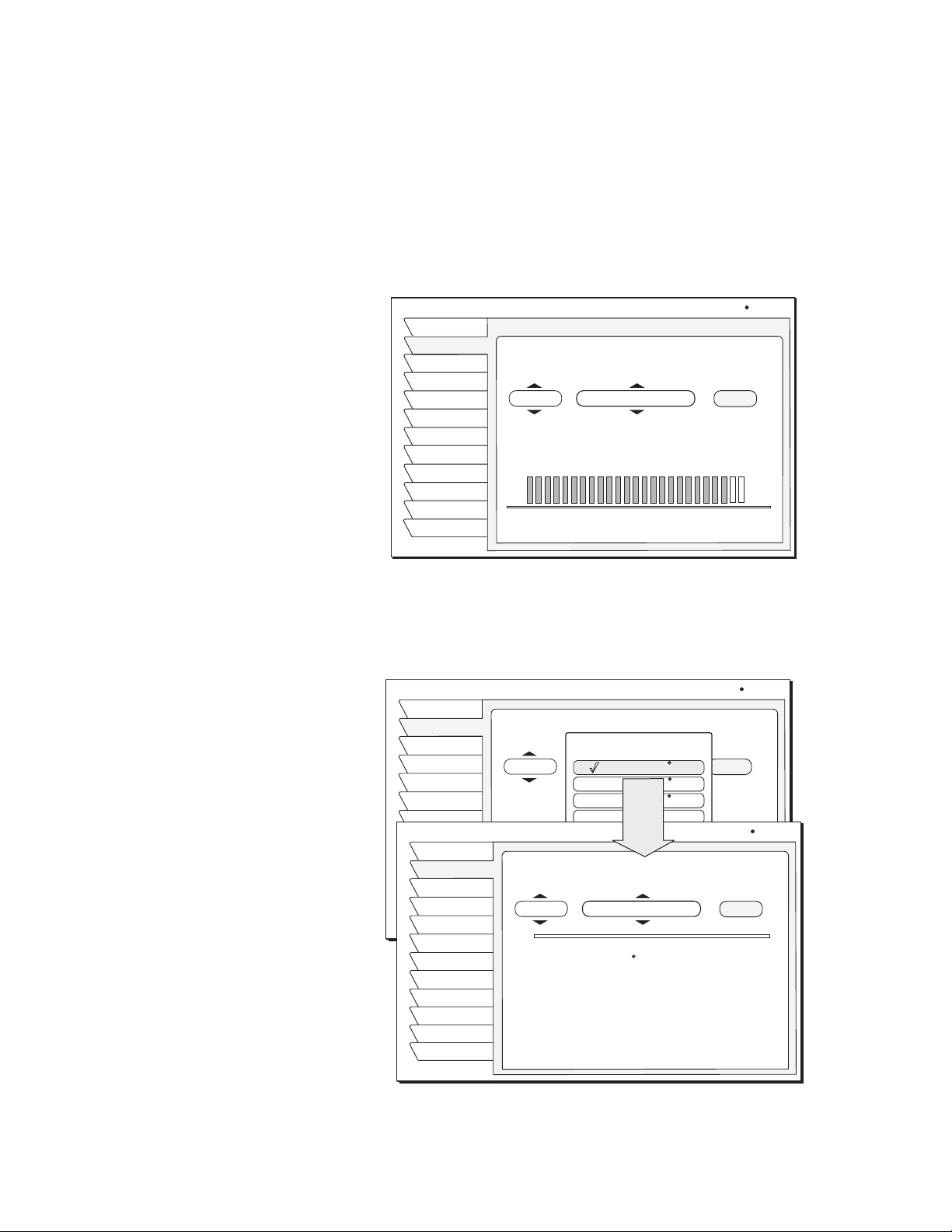
Setting TurboTune
channels:
1. Press the
TURBO button on the remote control to show the TurboTune grid
shown in the figure below.
2. Use the paddle or directional arrow buttons to highlight an unused
position (Add Channel) of the TurboTune grid.
3. Press SELECT to add the channel you are watching to the TurboTune menu.
DIRECTV Pay Per View Prev
Turbo 1Turbo 1 Turbo 2 Turbo 3
Add
Channel
SETUP
1. SELECT Guide Options from the MAIN MENU, then use the Set Turbo
menu tab or press the
Setup pane below the TurboTune Menu.
2. Highlight an unassigned channel box (Add Channel) and press
TURBO button on the remote control then SELECT the
SELECT.
20
Using program guides
Page 29

3. Choose the desired channel in the setup box shown below using
the paddle, directional arrow buttons, or the
CHANNEL(CH) button.
You can also use the numeric remote control buttons to enter specific channel
number.
Renaming TurboTune
groups:
TURBOTUNE SETUP
Theme
Times
Fav List
Fav Setup
Options
Set Turbo
Watch TV
Main Menu
Turbo 1Turbo 1 Turbo 2 Turbo 3
Add
Channel
Channel: DTV
MOVIE SHOWCASE previews whats hot
this week on DIRECTV premium movie
Channels HBO, STARTZ! and SHOWTIME.
500
Add
Channel
Movie.
Tue, Dec 17 6:00 PM
Add
Channel
OK
Cancel
Each nine-channel group can be renamed as anything you choose, using up to
10 letters, numbers, spaces, and punctuation. From the TurboTune grid:
1. Highlight the grid name (Turbo 1, Turbo 2, or Turbo 3) shown above.
2. Press
SELECT.
3. Use the on-screen keyboard to enter the new name.
4. Highlight and
Use the
Cancel or Clear menu buttons to redo the entry or cancel the change.
SELECT the OK menu button.
Using
DIRECTV INTERACTIVE
powered by Wink Communications
Select the DIRECTV INTERACTIVE
menu bar, then follow the
Center
simple directions provided on the
subsequent screens.
DIRECTV INTERACTIVE™ powered by Wink Communications® is a free,
easy-to-use service that allows you to interact with the television shows and
™
advertisements. When the blinking symbol appears on your screen, you
®
know that the program you're watching has been enhanced with
DIRECTV INTERACTIVE Service. Press the
SELECT button on your remote
control to access interactive features.
You can use your remote control to access up-to-the-minute sports scores, news
and weather, get program trivia, respond to offers during commercials, and
purchase products, all while watching TV.
DIRECTV INTERACTIVE
Interact
Watch TV
Main Menu
TM
DIRECTV INTERACTIVE
Check your local weather, see the
latest sports scores, interact with
popular shows and shop from your
couch. It is FREE, easy to use and
lots of fun!
Go to the DIRECTV INTERACTIVE
Center to get started.
DIRECTV INTERACTIVE Center
Wed, Oct 30 2:07PM
TM
Using program guides
21
Page 30

Setting guide
preferences
The GUIDE OPTIONS menu shown below allows you to customize the
appearance and behavior on-screen guides. To set guide preferences:
1. Highlight
press the remote control
2. Highlight the
3. Highlight and
and SELECT the Guide Options tab from the MAIN MENU, or
GUIDE button twice while watching a program.
Options tab
SELECT the menu button for the setting you wish to modify.
GUIDE OPTIONS
Theme
Times
Fav List
Fav Setup
Options
Set Turbo
Watch TV
Main Menu
Guide Style
Picture In Guide
Guide Zoom
Multi-Color
Channel Sort
Filters
Reset Options
Fri, Oct 4 12:25AM
Grid
On
On
On
Numeric
Temporary
22
Using program guides
Page 31

Using the menus 5
This chapter describes:
• How to find the menus you need to perform common tasks (this page).
• How to purchase pay per view events (see page 24).
• Using the Program Director (see page 28).
• How to set and modify preferences (see page 25).
The table below lists the
MAIN MENU tabs, their submenus, and what they do.
Main Menu tab Screens (see page) If you want to:
Program Guide Program Guide • View, and modify the program guide.
Guide Options Theme
Times
Favorites List
Favorites Setup
Set Options
Set Turbo
Audio & Video Audio Adjustment
Video Adjustment
Caller ID*Caller ID
(page 35)
(page 36)
(page 33)
(page 33)
(page 25)
(page 20)
(page 31)
(page 25)
(page 26)
• Filter the program guide.
• Change the period of time shown in the program guide
• Select a specific channel list (Fav. A, Fav. B, Fav. C, Family, and
New Channels) to be an active program guide.
• Create/Edit a channel list (Fav. A, Fav. B, Fav. C, Family, and New
Channels) that contains selected channels.
• Guide Options:
– Guide style (grid or Logo)
– Picture in guide, zoom (on or off)
– Multi-Color guide (on or off)
– Channel Sort (numeric or alpha)
– Filters, (temporary or persistent)
– Reset options to the default selections
• Set and edit TurboTune channels
• Set Default Audio language and Alternate Audio language
• Set left/right audio balance
• Select 4:3 or 16:9 screen ratio
• Center menus on your monitor (up/down and right/left)
• Color scheme, color balance, and on-screen display translucency
• See the names and telephone numbers of recent callers
Program Director Schedule
Watch Wizard Setup
Results
Interactive DIRECTV INTERACTIVE
Purchases Upcoming & Past Purchases
(page 24)
Lock & Limits Lock
Fav S etup
Rating
Limits
View Mail Mail
System Setup Install
Signal
VCR
Prefs
New Card
Upgrade
Features
(page 28)
(page 27)
(page 27)
(page 37)
(page 33)
(page 37)
(page 38)
(page 31)
(page 2)
(page 5)
(page 8)
(page 30)
™
(page 21)
• Automatically tune to programs for viewing or taping
• Search for programming using specific words and other criteria
• Display search results
• Access interactive programming features
• View a list of scheduled pay per view event
• Display recently purchased pay per view events
• Lock and unlock the system
• Set viewing times and maximum viewing hours
• Set maximum program rating allowed for viewing
• Create a program listing containing only selected channels
• Filter programming content in the program guide
• Read messages from DIRECTV
• Determine proper antenna azimuth and elevation setting
• Test signal reception
• Setup VCR for unattended recording
• Prepare a new access card
• Display upgrade status and history
• Adjusting user-selectable system settings
• Display current receiver feature
Using the menus
23
Page 32

Onscreen menu icons
These icons appear in onscreen menus and are used throughout this manual:
Toggle or Step Press SELECT to toggle (switch) a setting from ON to OFF or
step through the available choices each time you press SELECT.
List of Options Menu button will display a list of choices in a pop-up menu when
you press SELECT.
Series of Boxes Multiple screens will appear in a series requesting you to enter
numbers and/or letters for the particular feature when you
press SELECT.
Purchasing pay per
view (PPV) events
If you are not authorized for
purchases using your DIRECTV
Receiver, contact DIRECTV for
assistance.
Cancelling purchases
To purchase a pay per view event:
1. Highlight and
®
2. Press SELECT to display the PROGRAM INFORMATION screen below.
3.
SELECT the Buy menu button.
4. Press
SELECT again to confirm your purchase. You can also cancel the
SELECT the PPV event you wish to purchase.
purchase at this time if you change your mind.
PROGRAM INFORMATION
Program
Watch TV
Main Menu
Buy
$3.99
Program Title
Tue, Dec 17 5:00PM - 7:01PM
Rated:
Program description
Purchase Program
Back Times
Wed, Dec 17 2:54PM
101
You can usually cancel unviewed purchases, however some events cannot be
cancelled. If the Cancel Purchase button appears, you can clear the purchase.
If this button is unavailable, part of the event has probably already been viewed,
and you must accept the purchase.
24
Using the menus
Reviewing past
purchases
To cancel a Pay Per View event:
1. Highlight the event you want to cancel.
SELECT Cancel on the Purchase Confirmation panel.
2.
SELECT the Purchases menu tab to display lists of recently viewed and
advance purchased pay per view events. You can choose
PURCHASES
and PAST PURCHASES. The event channel, title, start date and
UPCOMING
time, and cost is shown for each purchase.
The PAST PURCHASES pane shows recent pay per view events charged to
your account. You cannot remove listed events. The list does not show:
• events purchased, but later canceled.
• purchased, cancelable events to which the DIRECTV Receiver never tuned.
• events ordered by calling DIRECTV.
Page 33

Listing unviewed
A
O
A
O
purchases
The UPCOMING PURCHASES pane displays PPV events you have purchased
but not yet viewed. Events ordered by calling DIRECTV do not appear on this
list. For additional information about a specific event, highlight the event and
press the
INFO key.
Adjusting audio
settings
Setting default and
alternate audio
Press the AUDIO button on your remote control or highlight and SELECT the
Audio & Video tab from the MAIN MENU.
From the
AUDIO ADJUSTMENT menu pane, you can:
• select default audio and alternate audio
®
• enable TruSurround
• enable and configure Dolby Digital output
audio processing
(Model HAH-SA only)
• adjust audio left/right balance
Your DIRECTV® Receiver supports alternate audio services. This icon
ALT.
UDI
appears below the date and time in the Information Banner or program guide to
indicate alternate audio is available for a particular program.
You will hear the Default Audio language all the time if that language is being
transmitted and an alternate language has not been activated. If your selected
default language is not being transmitted for a program, you will hear the
language in which the program is broadcast.
ALT.
If the icon appears below the date and time in the Information Banner or
UDI
program guide, pressing the navigation paddle or directional arrow buttons
left or right (while you are viewing a program) presents you with an alternate
available language option based your Alternate Audio menu selection. Press
SELECT to listen to program in the alternate language on the currently airing
channel. Audio will revert to your selected Default Audio language when you
change the channel.
Occasionally, an audio track may be
offered that is not being broadcast, in
which case the audio will not change
or you will not hear any audio.
Change channels to restore the audio
track to the one specified on the
AUDIO ADJUSTMENT
menu.
To set up your default and alternate audio languages:
1. Press the remote control
AUDIO button to access these services.
2. Highlight the Default Audio (to set your preferred primary language) menu
button or the Alternate Audio menu button (to select your secondary
language preference).
3. Highlight the desired language for the default or alternate language and
press
SELECT.
AUDIO ADJUSTMENT
Audio
Video
Watch TV
Main Menu
Default Audio
Default Audio
English
Spanish
Alternate Audio
French
Audio Balance
German
SRS TruSurround
Italian
Japanese
Dolby Digital
Korean
Chinese
Factory Defaults
Fri, Sep 20 2:15 AM
English
English
Center
On
On
Using the menus
25
Page 34

Using TruSurround
TruSurround technology lets you take advantage of any multichannel format
without having to add extra speakers or equipment. Using two speakers,
TruSurround “virtually” places the individual audio channels where they are
supposed to be, as though you had speakers all around you. To enable
TruSurround, set the SRS TruSurround menu button “On”.
Note: TruSurround and Dolby Digital are mutually exclusive features. TruSurround is
unavailable when the receiver is decoding a Dolby Digital (AC-3) audio track
.
Using Dolby Digital
audio
(Model HAH-SA only) If you want the receiver to automatically decode Dolby
Digital (AC-3) audio when available in selected programming, set the Dolby
Digital menu button “On.” If your A/V receiver is Dolby Digital-capable, set
the Digital Output menu button to “Dolby Digital.” Highlight and
SELECT the
Dolby Digital Options menu button.
AUDIO ADJUSTMENT
Audio
Video
Watch TV
Main Menu
Default Audio
Alternate Audio
Audio Balance
SRS TruSurround
Dolby Digital
Dolby Digital Options
Factory Defaults
Wed, Oct 16 2:15AM
English
English
Center
On
On
Dolby Digital Options
Digital Output
Optimize
Done
Dolby Digital
Stereo
Set the Digital Output menu button for “Dolby Digital” as shown in the figure.
If your A/V receiver cannot decode Dolby Digital audio, use the “PCM”
(two-channel) setting. Use the Optimize “Mono” setting if you connect the
satellite receiver to your TV using coaxial cable without A/V (left/right audio)
cables.
Adjusting video
settings
26
Using the menus
Press the AUDIO button on your remote control or highlight and SELECT the
Audio & Video tab from the MAIN MENU.
From the VIDEO ADJUSTMENT menu pane, you can:
• change the screen aspect ratio - 4:3 or 16:9
• center the on-screen menu
• select a different menu color scheme - Indigo, Ice, Sky, Forest, or Merlot
• adjust the amount of menu translucency - from Solid to 100% Translucent
• adjust image brightness, contrast, and saturation
• enable or disable black level filtering
Page 35

Using WatchWizard
™
WatchWizard™ allows you to search for programs using criteria such as rating,
showtime, language, and category. You can search for a specific word used in
program titles or descriptions.
WatchWizard can perform up to eight separate searches using any combination
of criteria and text.
To access WatchWizard, press the
SEARCH button on the remote control or
SELECT the WatchWizard tab from the MAIN MENU. Define your searches
using the
Highlight and
WATCHWIZARD SETUP pane shown on page 27
SELECT one of the eight search buttons..
WATCHWIZARD SETUP
WWSetup
WWResult
Channels
Watch TV
Main Menu
WatchWizard Program Searches
Search
Empty
Empty
Empty
Empty
Empty
Empty
Empty
Rename Clear Clear All
Wed, Oct. 2 1:45 PM
Results Guide
A search menu appears where you can enter your search criteria as shown
below. Narrow your search results by combining criteria and text entries.
WATCHWIZARD SETUP
WWSetup
WWResult
Channels
Watch TV
Main Menu
WatchWord
Search 1
Showtimes Category
Now
Ratings
All
Language
English
Reset
Wed, Oct. 27 1:11 PM
Movies, Action/Adventure
Director
All
Actor
All
Back
Highlight the
SELECT
Pressing the
WWResult to see a list of programs matching your search criteria.
the Results Guide menu button to view the search results as a guide.
SEARCH button on the remote control when any program guide is
onscreen automatically highlights programs matching your search results.
Pressing the
SEARCH button again highlights the next result based on program
starting time.
Use the on-screen keyboard to enter text (see figure on page 28). Press
SELECT
to enter the letter. Select OK when you are finished entering the desired text.
Using the menus
27
Page 36

You can highlight and
SELECT
the toggle icon on the
default button board to change
it to a standard keyboard
layout if you desire. Highlight
the desired letter using
the paddle or directional
arrow buttons.
WATCHWIZARD SETUP
WWSetup
WWResult
Channels
Watch TV
Main Menu
;
~:
!@# $ &
1 0
2
Q
W E R T YU I O P
A S D F G H J K L Ñ
Z
X C V B N M .,?
--
+
%
^
´
/ =
<
>
( )
*
9876543
Del
WatchWizard Entry
Search for words in the Program Titles
and Descriptions within Guide.
~:
!@# $ &
1 2 3 5
A
K L M N O P Q R S
T U V W X Y Z .,?
;
C4DEF G H I J
B
´
rodeo
--
+
<
>
casino
%
^
*
tropical
7
8 9 0
6
Roberts
Empty
Tue, Oct 15 9:23AM
/ =
( )
Ñ
Del
OK
Salir
Borrar
Using the Channels search
Using the Program
Director
You can also search for DIRECTV® channels showing a specific type of
programming by using the category-based channel search.
You can program up to 32 events in advance for viewing or unattended
recording by selecting
PROGRAM DIRECTOR menu allows you to automatically tune to a program at
Program Director from the MAIN MENU. The
a specific date and time, or tune to a program on a repeating basis. You can:
• schedule programs for viewing (
• schedule programs for taping ( ) (Model
• specify programs to record by title (Model
9)
HAH-SA only)
HAH-SA only)
• select Cancel from the menu if you decide not to schedule anything.
PROGRAM DIRECTOR
Schedule
By Title
Watch TV
Main Menu
Add and Modify Scheduled Events
Chan Start FrequencyLength
Schedule Options
Schedule to View ( )
Schedule to Tape ( )
Cancel
Wed, Oct 2 7:14PM
28
Using the menus
Page 37

Scheduling or editing an
event
There are three ways to schedule a program:
From the program guide:
You can schedule events up to
eleven months in advance.
If you specify a date, use the
month/day format. The year is set
automatically.
1. Highlight an upcoming program in the program guide and press
A
9 will appear next to your selection. Press SELECT again to cycle
SELECT.
through the next available option ( if available).
2. If you choose a scheduling option, the DIRECTV
®
Receiver will turn on
(if necessary) and tune to the specified channel at the chosen date and time.
3. If you chose Schedule to Tape and you have set up your VCR (see page 8),
the DIRECTV Receiver will record the event. For unattended recording:
– Attach the VCR Control Cable and set up your VCR.
– Set your VCR for the correct DIRECTV Receiver output: RF (channel
3/4) or A/V (phono or S-Video).
– Insert a blank videotape and leave the VCR turned on.
Fro m the
1. Highlight an empty slot and press
2.
3. Choose the desired channel from the channel selection pane.
PROGRAM DIRECTOR menu Schedule tab:
SELECT.
SELECT Schedule to View or Schedule to Tape from the Schedule
Options
menu.
SELECT OK.
4. Use the paddle or directional arrow buttons to specify AM or PM (or N
for noon, or M for midnight if you specified 12:00).
5. Use the same procedure to set the program Duration in hours and minutes.
6. Use the paddle or directional arrow buttons to advance to the Frequency
column.
7. Specify when, or how often, the event occurs: Tod ay, Tom or ro w, Every Mon,
Every Tue, Every Wed, Every Thu, Every Fri, Every Sat, Every Sun,
Everyday, Mon-Fri, or “/” (specify a date).
8. After setting the Frequency, use the paddle or directional arrow buttons
to advance.
9. Review your settings and choose OK, or choose Cancel to delete the edits.
To record a program by entering a title:
1. Highlight the
2. Highlight and
By Title tab under the PROGRAM DIRECTOR menu.
SELECT one of the program selection menu buttons.
3. Use the on-screen keyboard to enter the name of the program you want to
record.
4.
SELECT the OK menu button when you are finished.
The receiver will tune to the next and subsequent broadcasts of the specified
program and automatically record it.
Schedule pane displays up to eight events at a time. If more than eight
The
events are already scheduled, use the paddle or directional arrow buttons to
scroll down to view the additional events. Small arrows at the top or bottom of
the list indicate that there are additional events.
To cancel a program scheduled for viewing or taping:
Find the upcoming program in the program guide you wish to cancel and press
SELECT until the check mark (✓) or videotape icon ( ) disappears.
If the program is currently airing, you must delete the event from the
menu pane accessed from the
PROGRAM DIRECTOR.
Using the menus
Schedule
29
Page 38

Adjusting system
settings
Select the System tab from the MAIN MENU to access the system functions
described in this section. Use the
PREFERENCES menu pane (shown in the
figure below) to change the appearance of the on-screen menus and select how
your DIRECTV
®
Receiver operates with other devices. The PREFERENCES
pane also allows you to:
• Set the receiver output channel to channel 3 or 4
• Enable or disable the
INPUT button on your remote control.
• Select English or Spanish language menus.
• Specify your time zone.
• Enable or disable daylight saving time
• Select full or short channel banner style
• Enable or disable Caller ID
Set output channel
Input key enable/disable
Select menu language
PREFERENCES
Install
Signal
Info
Features
VCR
Prefs
Test
Remote
Test
New Card
Upgrade
Watch TV
Main Menu
Preference Settings
Output Channel
Input Key
Menu Language
Time zone
Daylight Saving
Banner Style
Caller ID
Factory Defaults
Fri, Oct 4 1:53PM
3
On
English
Default
Observed
Short
On
Use the Output Channel menu button to toggle between channels 3 and 4,
whichever is unused in your area.
The Input Key menu button allows you to turn the remote control INPUT button
on and off.
The Menu Language button allows you to display on-screen menus in English
(default) or Spanish.
Caller ID enable/disable
Restore factory default
settings
30
Using the menus
Use the Caller ID menu button to turn the Caller ID feature on and off.
Incoming calls will not be displayed on-screen when the Caller ID feature is
disabled.
Note: You must subscribe to Caller ID service from your telephone company to
use this feature.
SELECT the Factory Defaults menu button to restore the PREFERENCES
options to the original factory settings.
Antenna, Signal, and Test functions are described Chapter 1 –
Started
.
Getting
Page 39

Viewing Mail DIRECTV uses the MAIL feature to send you important information, inform you
of special events, and tell you about special offers.When you receive a new
message, a
message. Highlight and
New Mail
icon appears at the top of all menus until you read the
SELECT the View Mail tab from the MAIN MENU.
Message –
VIEW MAIL
Mail
Watch TV
Main Menu
SELECT the Messages button. Use the paddle or directional arrow
Erase
Read Message
Message
Second page of message text...
1 of 3 Page 2
Fri, Jul 6 5:24AM
buttons to navigate though messages.
Page – Use the
CHANNEL(CH) button to cycle through a multi-page message
when the cursor is in the Message area.
Erase – Permanently remove a message. Messages are automatically deleted as
they become outdated or if space is needed for newer incoming messages.
Using Caller ID Your DIRECTV
incoming call. The caller’s name and telephone number appears in a banner
across the lower portion of your screen while you’re watching TV.
*You must subscribe to Caller ID
from your local telephone
company to use this feature.
The Call History pane shows you the name, time, and telephone number of
recent calls on your TV as shown in the figure below. To display the
History
pane, highlight and SELECT the Caller ID tab from the MAIN MENU.
CALLER ID
Callers name
You can also highlight and SELECT a recent call from the Call History pane to
dial the number shown on the screen.
®
Receiver shows you CID information when you receive an
Call
Mon, Feb 3 3:42PM
Caller ID
Watch TV
Main Menu
Date of call
Today
John Customer
2/2/03
Joe Callow
Time the most recent
call was received
How many calls were received
from this number on this date
Call History
10:16 AM (765) 163-7133
4:20 PM
1
2
(405) 163-5256
Callers telephone number
Using the menus
31
Page 40

32
Using the menus
Page 41

Setting favorites and filters 6
This chapter explains:
• How to create a channel list (this page).
• Renaming a channel list (see page 34).
• Using Auto Set, Add All, and Del All functions (see page 34).
• How to filter the program guide (see page 35).
• How to change guide times (see page 36).
Using favorite
channel lists
Creating a channel list
Channel Lists are provided to help you organize the hundreds of available
channels into groupings suitable for your household. Each list can contain as
many or as few channels as you wish. You can customize these groups several
ways. For example, Fa v . A could be Dad’s favorite channels, Fa v. B could be
Mom’s favorites, Fav . C could be the kids’ channels, and Fa mi ly could be all
channels that Mom and Dad have deemed appropriate for the entire family.
1. Press the remote control MENU button.
2. Select the
3. Use the paddle or directional arrow buttons to highlight the
Guide Options or Lock & Limits from the MAIN MENU.
Fav Setup
tab.
4. Press
SELECT to open the FAVORITE LIST SETUP pane shown below.
FAVORITE LIST SETUP
Theme
Times
Fav List
Fav Setup
Options
Set Turbo
Watch TV
Main Menu
Channel
120 WABC
121 WQED
122 ESPN
123 HBOW
Quality entertainment for the whole family, featuring
animated XYZ classics, original series, entertainment
specials, and movies. Included at no additional charge
in DIRECTV TOTAL CHOICE Packages.
List: MYLIST
Fri, Sep 18 6:00 PM
Auto Set
Rename
Add All
Delete All
New Chan26New Channels
The four columns of small boxes on the right hand side of the pane are the Tag
Boxes. The first three columns are the Fa v. A, Fa v. B , and Fa v. C. channel lists.
The farthest right hand column is the Fa m il y list.
Note: If the Family list has not had channels added to it, no channels can be
viewed without first unlocking the receiver. To avoid this inconvenience, create
the Family list before locking the receiver. See Chapter 7 – Using access
controls, on page 37 for additional details about controlling system access.
5. Use the paddle or directional arrow buttons to highlight the tag box that
corresponds to the channel number and list that you wish to create or
change.
6. Press
SELECT to add or remove the check mark, which indicates that the
channel in that row is included in the list shown at the top of the column.
Setting favorites and filters
33
Page 42

7. Scroll up or down to view channels and descriptions. Press SELECT to add
channels to your list.
8. When you have added all of the channels you want to your list, use the
paddle or directional arrow buttons to highlight and
SELECT the Watch TV
tab to resume viewing.
Renaming a channel list:
Once you have created your lists, use the remote control
FAV button to cycle
through them quickly and easily. Each press cycles to next channel list.
You can also select a list by highlighting the
Options
menu..
FAVORITE LIST
Theme
Times
Fav List
Fav Setup
Options
Set Turbo
Watch TV
Main Menu
Select Favorite List to filter Guide
Fav List tab from the Guide
Wed, Jul 18 8:16 PM
All Channels
FAV. A
FAV. B
FAV. C
Family
New Channels
This list has 380 Channels
1. Highlight the Rename button and press SELECT.
A
Rename List menu appears. You can rename the first three lists. You
cannot rename the All and Fa mi ly lists.
2. Highlight the list you wish to rename and press
SELECT. A keyboard panel
appears.
3. Highlight the desired letter using the paddle or directional arrow buttons
and press
SELECT.
4. When finished, Select OK.
Creating an Auto Set list
Adding and removing
channels
34
Setting favorites and filters
1. SELECT the Auto Set button.
2. Highlight and
Once selected, the
SELECT a channel list to be programmed.
Auto Set Progress status panel appears. It may take
several minutes for the receiver to scan through all of the channels and
determine which ones you are authorized to receive. The results of this scan
will be stored in the designated channel list.
Note: Auto Set may exclude some channels such as the Music Choice
channels or include some pay per view channels. This does not mean that
the receiver is faulty. These channels were excluded or included due to the
DIRECTV
®
Receiver’s analysis process. You can manually edit the lists to
correct these oversights.
Selecting the Del All menu button clears all channels from the list you have
chosen. Add All has the opposite effect, creating a list of all the channels
available on the DIRECTV
®
network.
To add or delete individual channels from your favorites lists, move the
highlight to List boxes for the particular channel you wish to add or remove and
Page 43

press SELECT. A checkmark (9) appears in the box if the channel has been
selected or the checkmark disappears to indicate the channel is not selected.
Finding new channels
Filtering the program
guide
Using Theme Filters
Occasionally, new channels are added to the available programming selections.
The number of channels that have been added since you created your channel
list appear in the New Channels window on the
FAVORITE LIST SETUP pane.
These channels appear in their own guide when you select New Channels in the
FAVO R I TE L I ST menu pane.
Press the remote control GUIDE button while a program guide is onscreen or
select the
CATEGORY FILTER menu. The menu provides filtering tools and ways to
GUIDE OPTIONS tab from the MAIN MENU to display the
access other guide styles. By combining each of these filter options, you can
quickly narrow down channels to those that match your viewing interests.
The CATEGORY FILTER menu allows you to filter the guide by program
category groups.
CATEGORY FILTER
Theme
Times
Fav List
Fav Setup
Options
Set Turbo
Watch TV
Main Menu
Select a Category to filter Guide
All
Movies
Sports
Interests
Lifestyles
News
Themes
Wed, Sep 18 4:20PM
The material is a movie, either
theatrical or made-for-TV.
After choosing a category (other than All), the menu is replaced by the
Subcategory menu panel. This menu allows you to further refine a chosen
theme. In addition to All, you can select popular categories that can be quickly
selected using the remote control
GUIDE button.
For example, if you select the Movies category, you can then refine your
selection using a subcategory such as Action/Adventure, Animation,
Biography, Comedy, and others as shown in the figure on page 36.
Setting favorites and filters
35
Page 44

CATEGORY FILTER
Theme
Times
Fav List
Fav Setup
Options
Set Turbo
Watch TV
Main Menu
Select a Category to filter Guide
All
Movies
Sports
Interests
Lifestyles
News
Themes
The material is a movie, either
theatrical or made-for-TV.
A description of the selected category appears here.
Wed, Sep 18 4:20PM
Movies
PREV LEVEL
All
Action/Adventure
Animation
Biography
Comedy
Current Affairs
Content Advisories
After selecting a subcategory, the guide will be further filtered to show only
those channels offering programs of the selected category and subcategory.
In this example, the guide would display channels featuring Action/Adventure
movies.
Selecting guide times
Highlight the Times menu tab. The GUIDE TIMES menu shown below provides
easy access to future programming information. Simply select the day you want
the guide to begin. Use the AM/PM menu button to select the proper time. The
program guide showing the selected time will appear onscreen.
GUIDE TIMES
Theme
Times
Fav List
Fav Setup
Options
Set Turbo
Watch TV
Main Menu
Advance the Program Guide
to the Selected Time
Thursday, September 19
5:00 PM
Th19Fr20Sa21Su22Mo23Tu24We
Th19Fr20Sa21Su22Mo23Tu24We
Th19Fr20Sa21Su22Mo23Tu24We
Navigate by using the arrow keys.
SELECT
Press to choose the time.
Thu, Sep 19 5:15PM
AM / PM
25
25
25
36
Setting favorites and filters
Page 45

Using access controls 7
This chapter explains:
• How to lock and unlock the system.
• How to set maximum rating, spending, and time limits.
Locks & Limits provides settings to help you control the viewing restrictions of
DIRECTV
provide a great degree of control. The DIRECTV
the TV Timer, Rating and Spending limits to be enforced.
®
programming. When accompanied by the channel lists, these limits
®
Receiver must be locked for
Locking & unlocking
the system
How to lock the system
Press Cancel to clear the locking
process.
If you forget your four-digit code,
you must call DIRECTV.
Unlocking the system
The button used to lock the system
is also used to unlock the system.
When you first receive your satellite system, it will be unlocked; (i.e., no limits
or restrictions are in effect). You must lock the system to enforce the limits
(spending, ratings, TV timer, and “Family” favorite list).
Note: Once the DIRECTV Receiver is locked, only existing Family list
channels will be accessible. If the Family list does not contain any channels, no
channels can be viewed without first unlocking the receiver. To avoid this,
verify the contents of the Family list before locking the receiver.
When you SELECT the Lock button, the LOCK SYSTEM pop-up panel appears.
1. Enter a four-digit passcode using the remote control then
2. Enter the code again to confirm, then SELECT OK.
SELECT OK.
Once you select OK, the satellite receiver is locked. You must enter the passcode
to unlock it. A lock symbol icon appears at the top of every menu screen to
remind you that the system is locked.
To remove the lock and its restrictions:
1. Highlight the
2.
SELECT the Unlock menu button.
Locks & Limits tab from the MAIN MENU.
3. Enter the same code you entered to lock the system.
Once the system is unlocked, all limits and restrictions are removed!
Choose Cancel to keep the lock in effect.
Setting ratings limits
Program ratings help you determine if a program’s content is appropriate for a
RATINGS LIMITS
Lock
Fav Setup
Ratings
Limits
Watch TV
Main Menu
Children
General Audience
Dialogue
Sex
Violence
Language
Movies
Not Rated
Sat, Oct 5 4:40PM
Allow All
Allow TV-14
Allow TV-14
Allow TV-14
Allow TV-14
Allow TV-14
Allow PG
Allow All
Using access controls
37
Page 46

particular audience. To select the maximum ratings limits allowed to be viewed,
highlight the
Ratings tab, then SELECT the type programming you wish to
restrict. For example, if you select the Violence menu button, a ratings pop-up
submenu appears as shown in the figure below.
Setting spending and
time limits
RATINGS LIMITS
Highlight and
Lock
Fav Setup
Ratings
Limits
Watch TV
Main Menu
Violence
Parental Guidance Suggested.
Violence
Children
Block All
TV-PG
TV-14
TV-MA
Allow All
Movies
Not Rated
SELECT the highest rating for violent program content you wish
Sat, Oct 5 7:17PM
Allow All
Allow TV-14
Allow TV-14
Allow TV-14
Block All
Allow TV-14
Allow PG
Allow All
to allow. You may choose to Block All or Allow All instead of setting a specific
limit.
Highlight the Limits tab to set the maximum spending limit. You can set the
maximum purchase price on a per-event basis. To change the displayed limit:
1. Highlight the Max Spending button.
2. Press
SELECT to display the SPENDING LIMIT pop-up panel.
Use this menu to set the specific hours and/or maximum hours the satellite
receiver can be used for viewing.
SPENDING/VIEWING LIMITS
Lock
Fav Setup
Ratings
Limits
Watch TV
Main Menu
Max Spending
Monday
Tuesday
Wednesday
Thursday
Friday
Saturday
Sunday
Total time watched today: 1:12
Wed, Jul 18 10:11AM
$5.00
24:00 Hours allowed
24:00 Hours allowed
24:00 Hours allowed
24:00 Hours allowed
24:00 Hours allowed
24:00 Hours allowed
24:00 Hours allowed
1. Use the number buttons on the remote control to set the limit or use the
paddle to increase or decrease each digit.
2. Use the paddle to highlight the digit that you want to change.
3. Highlight OK and press
SELECT to confirm the entered amount.
38
Using access controls
Page 47

Questions & Answers A
Questions? Did we forget to tell you something? We have compiled some the
most common questions and their answers here. We hope they help!
Q I had a signal but now I am getting a message “Searching for satellite
signal. To access related utilities, press
A Rain clouds and snow can affect the satellite signal reception. This loss of
signal is temporary. Also check for new growth on trees and bushes that
could be blocking the signal. One other possibility is that the wind or
someone has moved the satellite dish antenna.
Q Why can’t I control my TV?
A Before you can control your TV, VCR, or any other device besides your
satellite receiver, you must program your remote control to match your
different devices. See Chapter 3 –
for specific instructions. If you have already successfully programmed your
remote control, try pressing the appropriate device key to put your remote in
the proper mode. Then try controlling that device. Also, make sure that the
batteries in the remote control are good.
Q My satellite receiver does not respond when I press keys. What’s wrong?
SELECT
Using the remote control
.” What happened?
in this manual
A Most likely, if the front panel keys work but the remote control doesn’t
work, try pressing the
receiver. If that doesn’t work, press the
try again. If that doesn’t work, or if the front panel buttons don’t work
either, unplug your digital satellite receiver for 30 seconds, then plug it back
in. Your satellite receiver is a computing device. It is susceptible to erratic
changes in power and/or signal, just as any other computer, and these
sudden changes can cause it to become “confused.”
Q Some channels look good, while others freeze or indicate that no signal is
available. What’s wrong?
A The most common causes for this behavior relate to an improperly
grounded satellite cable. Check the cable between your digital satellite
receiver and the satellite dish antenna. Confirm that RG-6 (not RG-59)
cable is used and does not exceed 100 feet in length. Longer cable runs
require amplification. This special amplifier is available from your dealer.
Q I’m getting a message to call some extension. Why?
A There are many different reasons for this. If you want to watch the channel
that is displaying the message, call DIRECTV at 1-800-531-5000.
Q Why don’t I have an on-screen offer to purchase pay per view programs?
A There are three possibilities; your digital satellite receiver must be
connected to a phone line and it is not, or DIRECTV doesn’t realize that
your phone line is connected or has disabled your ability to make on-screen
purchases. Call DIRECTV at 1-800-531-5000 for assistance.
SAT button before trying to control the digital satellite
SAT and MUTE buttons together and
Questions & Answers
39
Page 48

Q Can I receive my local TV programs through my digital satellite receiver?
A There are three ways to receive local programming:
• If you are in an area where local programming is available via satellite and
have the proper satellite dish antenna, contact DIRECTV to arrange for
the necessary subscription package.
• Install a traditional antenna (i.e., roof mounted, attic mounted, rabbit ears).
• Arrange for basic or “lifeline” cable TV service from your local cable
company.
If you select item 1 above, your local programming appears in the program
guide like any other channel. For options 2 or 3, connect the local signal to
the
IN FROM ANTENNA jack on the back of your digital satellite receiver.
Use the
programming provided on the
INPUT key to switch between DIRECTV
OUT TO TV connector.
®
programming and local
Q I don’t see Caller ID information appear on screen when I receive a
telephone call. What could be wrong?
A There are several possible reasons. First, check that the satellite receiver is
connected to an active telephone jack. Verify that the Caller ID feature is
turned on (refer to page 30). Confirm that you subscribe to Caller ID service
from your telephone company. Also check that your antenna is properly
grounded as shown on page iv, as this can affect how the Caller ID feature
works.
Q If I have questions about my satellite system or need to have it serviced, who
should I call?
A For issues regarding your equipment, contact Hughes Consumer Care
Center directly at 1-800-274-8995, or if you prefer, call your dealer first.
They are most familiar with your installation and needs. Also, they are
likely to be local to you.
If you need assistance with your subscription, such as adding channels,
contact DIRECTV at 1-800-531-5000.
Q I think I set an event to record on my VCR, but when I played the tape back
nothing was there. What could be wrong?
A There are several possible reasons for this. First, check that the VCR was
programmed correctly and left turned on and the input matches the output
from your digital satellite receiver. Confirm that you were authorized to tape
the chosen program.
Q Why do I need to connect the satellite receiver to a telephone line?
A The telephone connection is used by the satellite receiver report purchase
activity to DIRECTV.
Q I picked up my telephone and it was making a hissing and squealing sound.
Why?
40
Questions & Answers
A Your digital satellite receiver was reporting any pay per view activity that
may have occurred. This rarely happens and only lasts for a minute or so.
Q What if my question isn’t listed here?
A Call your dealer or Hughes Consumer Care Center at 1-800-274-8995.
We will do our very best to answer your questions.
Page 49

Manufacturers device control codes B
Use these codes to program your remote control to operate your components.
Table 3: VCR brands and remote control codes
BRAND CODE NUMBER BRAND CODE NUMBER BRAND CODE NUMBER
Admiral
Adventura
Aiko
Aiwa
Akai
American
Action
American
High
Ampro
Anam
Asha
Audio
Dynamics
Audiovox
Beaumark
Broksonic
Calix
Canon
Capehart
CCE
Cineral
Citizen
Colt
Craig
Curtis Mathes
Cybernex
Daewoo
Daytron
DBX
Dimensia
Dynatech
Electrohome
Electrophonic
Emerson
Fisher
Fuji
Funai
025 053
034
117
034 101
016 043 046 124 125 146
117
031
072
031
040
012 023 039 043
101
040
025 035 037 044 129 152
101
028 031
108
024 117
117
101 117
024
003 024 101 040 135
031 041 156
040
005 007 010 065 108 110 112 116 117
119
108
012 023 039 043
156
034 053
059 101
101
006 017 025 027 029 031 034 035 036
037 044 046 101 117 129 131 138 152
153 157
003 008 009 010
031
034
Garrard
GE
GO Video
Goldstar/LG
Harley
Davidson
Harman
Kardon
Harwood
Hitachi
Hughes
HQ
Instantreplay
JCL
JCPenney
Jensen
JVC
KEC
Kenwood
KLH
Kodak
Lloyd
Logik
LXI
Magin
Magnasonic
Magnavox
Marantz
Marta
Matsui
Matsushita
MEI
Memorex
MGA
MGN
Technology
Minolta
Mitsubishi
034
031 040 053 063 072 107 109 126 144
147 151 156
040 132 136
001 101 012 114 123
034
012 045
024
001 026 034 063 137 150 156
001
034
031
031
001 012 031 040 066 101 156
043
048 050 043 130 060 012 031 150 055
158
101 117
014 023 034 047 048
024
031 101
034
024
034 003 009 017 101
040
117
067 031 034 041 064 068 154 160
012 023 031 067 069
101
027 030
031
031
003 010 014 025 031 034 040 053 072
101 102 134 139
045 046 059
040
001 156
001 045 046 053 059 061 162
Motorola
MTC
Multitech
NEC
Nikko
Noblex
Nordmende
Olympus
Optimus
Optonica
Orion
Panasonic
Pentax
Philco
Philips
Pilot
Pioneer
Portland
Profitronic
Protec
Quartz
Quasar
Radio Shack
Radix
Randex
RCA
Realistic
Rico
Salora
Samsung
Sanky
Sansui
Sanyo
Scott
031 053
034 040
024 034
012 023 039 043 048
101
040
043
031
053 101
053 054
025
031 066 070 133 160 161
001 031 063 156
025 031 034 067
031 034 054 067 071 101
101
001 021 048
108
040
024
002 014
031 066 070 133 160 161
034 123
101
101
001 031 034 040 041 053 107 109 140
144 147 151 156
003 008 010 014 031 034 040 053 054
101
058 078
014
032 040 102 104 107 109 112 113 115
120 122 125 159
053
022 025 034 043 048 135
003 010 007 014 040 102 134
017 037 044 112 129 131 159
Manufacturers device control codes
41
Page 50

Table 3: VCR brands and remote control codes
BRAND CODE NUMBER BRAND CODE NUMBER BRAND CODE NUMBER
Sears
Sharp
Shintom
Shogun
Signature
Singer
Sony
Soundesign
STS
Sylvania
Symphonic
Tandy
001 003 008 009 010 014 017 031 034
081 101
031 054 053 143
024
040
034
024
003 031 032 034 052 056 057 058 155
034
001
031 034 059 067
034
010 034
Tatung
Teac
Technics
Teknica
Thomas
TMK
Tos hi ba
Tatung
Teac
Totevision
Unitech
Vector
023 039 043
023 034 039 043
031 070
031 019 034 101
034
040
001 008 042 047 059 082 112 131
023 039 043
023 034 039 043
040 101
040
012
Video
Concepts
Videosonic
Wards
Westinghouse
XR-1000
Yam aha
Zenith
012 034 046
040
001 003 017 024 031 034 040 053 054
131
024 025
024 031 034
012 034 039 043
025 034 048 056 058 072 080 101
Table 4: Television brands and remote control codes
BRAND CODE NUMBER BRAND CODE NUMBER BRAND CODE NUMBER
Admiral
Aiko
Akai
Alaron
A Mark
America
Action
Amstrad
Anam
AOC
Audiovox
Baysonic
Bell&Howell
Blaupunkt
Bradford
Brooksonic
Cairn
Candle
Capehart
Carver
CCE
Celebrity
Cetronic
Cineral
Citizen
072 081 096 160 161
103
070 146
028
112 143
043
052
043 054 056 080 112
004 058 070 112
043 076 103 120
043
072
088
043
096
206
002 003 004 070
058
164
001 004 024
001
043
103 120
002 003 004 043 070 101 103
143
Classic
Concerto
Contec
Coronado
Craig
Crosley
Crown
Curtis
CXC
Daewoo
Daytron
Denon
Dumont
Dynasty
Dynatech
Electroband
Electrohome
Emerson
Fisher
Fujitsu
Funal
Futuretech
GE
Gibralter
043
004
043 050 051
143
043 054 191
164
043 143
004 011 070 072 081 101 120 143 164
043
004 016 043 044 076 103 114 120 127
128 136 143 192
004 143
011
004 073
043
062
001
024 076 120 143
004 005 028 043 047 048 050 051
070 076 096 120 143 151 153 154
155 191
007 057
028 198 210 211
028 043 052
043
004 008 009 034 056 070 073 074 081
120 130 145 155 160 165 161 167
004 073
Goldstar/LG
Gradiente
Grunpy
Hall Mark
Harley
Davidson
Harvard
Hitachi
Harman
Infinity
Inteq
JBL
JCB
JCPenney
Jensen
JVC
KEC
Kenwood
Kloss
KMC
KTV
Lodgenet
Loewe
Logik
Luxman
004 106 110 112 119 127 143 193
004 038 106
028 043
004
028
043
004 007 009 010 011 012 023 072 075 143 158
164
164
073
164
001
004 008 009 024 030 065 070 101 143
156 160
013
001 034 038 083 199 208
043
001 070
002 059
143
043 070 143 154
072
209 211
072
004
42
Manufacturers device control codes
Page 51

Table 4: Television brands and remote control codes
BRAND CODE NUMBER BRAND CODE NUMBER BRAND CODE NUMBER
LXI
Magnavox
Majestic
Marantz 070 164
Matsui 164
Matsushita
Megatron
Memorex
Metz
MGA
Midland
Minerva
Minutz
Mitsubishi
Motorola
MTC
Multitech
NAD
NEC
Nikei
Nikko
NTC
Onking
Onwa
Optimus
Optonica
Orion
Panasonic
Philco
007 015 052 081 160 164
003 004 022 059 060 061 063
064 070 094 127 160 164
072
080
-
004 007 028 072 096
088
004 024 024 028 042 070
073
088
008
004 024 028 040 042 081 146
214
081
070 004 062 101
043
015 025
004 016 019 024 040 056 070
130 134
043
103
103
043
043
080
019 081
028 096 201 202 203 204 205
034 056 080 164 212
003 004 024 056 059 060 063
064 070 164
Philips
Pioneer
Portland
Prism
Proscan
Proton
Quasar
Radio Shack
RCA
Realistic
Runco
Sampo
Samsung
Sansei
Sansui
Sanyo
Scotch
Scott
Sears
Seleco
Semivox
Semp
Sharp
Siemens
Signature
Sony
Soundesign
Spectricon
Squareview
164 093 038 005 059 127 070 003 004
213
025 070 004 018 023 190
004 143 065 103
034
160 161 167 145 065
004 058 112 143 171 173
034 056 080 164
004 019 043 127 143
160 161 156 165 065 070 004 023 024
056 074 081 152 167 145
007 019 043 047
073 130
004 070 058 207
101 004 050 089 105 160 127 143 133
215
120
096
007 020 053 057 082
004
004 028 043 048 143
004 007 015 028 030 052 057 082 094
143 160 164 167
200
043
015
004 014 019 022 028 081 143
088
072
001 079 126
003 004 028 043
112
052
SSS
Starlight
Supre Macy
Supreme
Sylvania
Symphonics
Tandy
Tatung
Technics
Technol Ace
Techwood
Teknika
Tel er ent
Ter a
TMK
TNCI
Tos hi ba
Universal
Video
Concepts
Vidikron
Vidtech
Wards
Westinghouse
Yam aha
Yor k
Yupi teru
Zenith
Zonda
004 043
043
002
001
003 044 059 060 063 064 070 127 160 164
194 052
081
056 062
034 080
028
004
002 003 004 024 028 043 072 101 103 143 164
072
173
004
073
015 030 007 040 062 101
008 009
146
164
004
004 008 009 019 028 060 061 063 064 072 074
143 164 165
120 076
004 070
004
043
011 072 073 095 096 103
112
Table 5: AUX audio brands and remote control codes
AUX CODE NUMBER AUX CODE NUMBER AUX CODE NUMBER
Adcom
AMC
Arcam
Audio File
Audio Techinica
Aiwa
Akal
Anam
146 149 227 244
083 084
100
093 098
221
111 114 117 156 170 199 203
219 231 241 254
181 233
180
Bose
B & K
Carver
Clarion
Denon
Englightene
d Audio
Fisher
Fosgate
064 137 219
150 152
013 098 107 126 129 160 163 220 245
249
151 169
101 133 191 202 208 246 247
078 153
107 129 157 163 176
228 248
GE
Harmon
Haitai
Hitachi
JCPenney
Jensen
Jerrold
JVC
123 216
073 195 248 249
119
088
109 154 178
099
141
112 198 252
Manufacturers device control codes
43
Page 52

Table 5: AUX audio brands and remote control codes
AUX CODE NUMBER AUX CODE NUMBER AUX CODE NUMBER
Kenwood
Krell
Lexicon
Luxman
LXI
Magnavox
Marantz
McIntosh
Mondial
MCS
Mitsubishi
Meridian
NAD
Nakamichi
096 104 119 125 148 151 163
171 173 242
223
215 250
066 120 205 229
123 177
126 162 185 186 224 228
074 105 126 128 139 155 162
186 232
251
069 225
178
253
013 067
128
072 212 234 235
Niles
Onkyo
Optimus
Panasonic
Parasound
Philips
Pioneer
Quasar
RCA
Realistic
Rotel
Sansui
Sanyo
Samsung
236
094 115 116 209 211 255
121 125 140 181
131 144 187 200
085 086 090
126 136 186 197
081 093 138 165 189 195 230 243
131 187
109 166 213
103 122 123 124 172 174 177 179 180
204 218 239
075 126 139 196 197 214
129 157
068
Scott
Sharp
Sherwood
Sony
Soundstrea
Starcom
Symphonic
Teac
Technics
Tos hi ba
Wards
Yam aha
Zenith
180 190
096 125 151 161 169 182 193
089 127
097 117 147 183 188 192 200 237 238 253
197
141
124
062 102 159 180
131 165 184 187 200 202 208
175
163
092 120 125 166 169 216 240
061 222
Table 6: AUX-CATV brands and remote control codes
CATV CODE NUMBER CATV CODE NUMBER CATV CODE NUMBER
Hamlin
Jerrold/G.I
Oak
015 017 022
010 021 025
008 016 023
Pioneer
Scientific Atlanta
TOCOM
007 026 027
002 006 013
003
Zenith
004
Table 7: DVD player brands and remote control codes
BRAND CODE NUMBERS BRAND CODE NUMBERS BRAND CODE NUMBERS
Alpine
Apex Digital
Arcam
Cyberhome
Daewoo
Denon
GE
Goldstar/ LG
Harmon Kardon
Hitachi
Hiteker
JVC
009
075 076
065
087
087
030 226
035 036
028 041
217
011
076
031
Kenwood
Magnavox
Marantz
McIntosh
Mitsubishi
NAD
Onkyo
Optimus
Panasonic
Philips
Pioneer
Proceed
070
008 038 042
006 007
071
032
077
207
034
003 039
006 007 038 042 063
005 010 034
002
Proscan
RCA
Samsung
Sharp
Sony
Technics
Theta Digital
Tos hi ba
Yam aha
Zenith
035 036
035 036
029 040 095
004
037 080
003
034
001 038 082 091 206
039 079
028 041
Table 8: DVD-Laser Disc Player brands and remote control codes
BRAND CODE NUMBER BRAND CODE NUMBER BRAND CODE NUMBER
California Audio
Denon
Fisher
Kenwood
Magnavox
Mitsubishi
047
043 044
047
060
048 057
057
NAD
Panasonic
Philips
Pioneer
Quasar
RCA
057
047 051 054
048
055 057
047
046
Sanyo
Sharp
Sony
Technics
Tos hi ba
Yam aha
052
060
050 053
047 051 054
060
045 059
44
Manufacturers device control codes
Page 53

A
A/V receiver, connecting 9
Advance select 28
Aligning the antenna 4
Alternate audio 25
Antenna
alignment values 4
cable, connecting 2
pointing 4
terrestrial 7
Audio
balance 25
AUX audio brands and control codes 43
Azimuth angle, determining 4
B
Batteries, installiing 15
C
Caller ID service 31
Caller ID, disable 30
Can’t Tape message 9
Cancel purchase 24
CATV brands and remote control codes 44
Changing menu language 30
Channel banner
location 19
removing from screen 19
CLEAR button 13
Codes, device control 41
Controls
device 14, 41
front panel 4
VCR, testing 8
D
Default audio 25
Delete event, preselected 29
Device control codes 41
DIRECTOR buttons 13
Dish antenna pointing 4
Dolby
digital connection 9
Pro Logic 9
DVD player remote control codes 44
E
Edit preselected program 29
Elevation angle, determining 4
English language menus 30
Entertainment system, connecting 9
F
Factory settings, restore 30
Front panel controls 4
G
Guide
features 19
grid style 17
logo style 18
selecting style 17
styles 17
GUIDE button 13
H
History, purchase 24
I
Icons
interactive features 21
menu 24
multiple box 24
new mail 31
on-screen display 24
option list 24
taping 28
toggle 24
viewing 28
ID, receiver 15
Info Banner, using 19
INFO button 13
INPUT button 13
Input key enable 30
J
Joystick
functions 11, 12
icon 13
L
Language, menu 30
Locate satellite 4
M
Mail
Erase 31
message 31
viewing 31
Menu
features 19
function overview 23
icons 24
language 30
tabs 19
Multiple box icon 24
N
New mail icon 31
O
On-screen menu language 30
Options list icon 24
Ordering events via phone 24
Output channel, setting 30
P
Past purchases pane 24
Pay per view
history 24
purchase 24
upcoming events 25
Phone jack connection 3
Picture-In-Guide
options 17
Preferences, system 30
Program guide
features 19
styles 17
Purchase Pay Per View event 24
Purchases not listed 24
R
Rear panel
connections 2
phone jack connector 3
Recording
unattended 28
VCR setup 29
Remote control
batteries 15
changing ID 15
manufacturers device codes 41
models 11
programming 14
quick reference 11, 12
sensor, VCR 8
TV codes 42
Replacing batteries 15
Restore factory settings 30
S
SAT button 13
Scanning remote control codes 11
Schedule programs 28
Search for words 27
Signal indication 5
Spanish language menus 30
Surround sound, Dolby 9
S-Video connection 3
System menu functions 30
System Setup screen 4
T
Tabs, menu 19
Tag boxes 33
Telephone connection 3
Testing
results 5, 6
satellite signal 5
Transponder
signal strength 5
testing 5
TurboTune, assigning channels 20
TV connection types 3
TV remote control codes 42
U
Unattended recording 29
Unviewed purchases 24
Upcoming purchases menu 25
V
VCR
Brands 41
connecting 7
control cable 8
control codes 41
remote control sensor 8
testing 8
W
WatchWord entries 27
Z
ZIP code antenna alignment 4
45
Page 54

Limited Warranty
Hughes Network Systems (HNS) provides the following limited
equipment warranty on this equipment.
This limited warranty is in lieu of all other warranties, whether express,
implied, or statutory, including, without limitation, the implied warranties
of merchantability and fitness for a particular purpose. HNS shall not be
liable for damages in excess of the purchase price of the product less
reasonable amount for use and wear, or for any incidental, special,
punitive, or consequential damages of any nature whatsoever, or for any
delays, loss of use, time, profits, revenue or savings, any commercial loss,
inconvenience, damage to buyer's or to other person's property, arising
from the use or inability to use the product, or otherwise for any failure to
perform.
Provisions
®
Your Hughes manufactured DIRECTV
and Remote Control are warranted against defects in materials and
workmanship for parts and labor.
Par t
Warranty
Per iod
HAH-SA
Satellite
Receiver
1 year parts,
90 days
HBH-SA,
SD-HBH
Satellite
Receiver
1 year parts,
90 days
labor
Receiver, Satellite dish Antenna,
HRMC-11,
HRMC-12,
HRMC-13
Remote
Control
90 days
parts
labor
HANT-XX
Dish and
LNB(s)
1 year
parts
HNS neither assumes nor authorizes any customer care center or any other
person or entity to assume any other obligation or liability beyond that
which is provided for in this limited warranty. No oral or written
information or advice given by HNS, its dealers, distributors, agents or
employees, shall create a warranty or in any way increase the scope of this
warranty.
Some states do not allow the exclusion or limitation of incidental or
consequential damages, or limitations of implied warranties, so the above
limitations or exclusions may not apply to Purchaser.
This Limited Warranty gives specific legal rights to Purchaser, and
Purchaser also may have other rights which may vary from state to state.
This limited warranty does not cover:
• a unit that has been modified
• damage from misuse, negligence, or accident
• any installation, or damages caused by installation
• shipments to HNS that are damaged in transit
• removal and reinstallation of equipment for repair
• loss of programming
• cost of shipping to HNS
• batteries or cables after installation
• acts of God
This limited warranty is not transferable and is valid only in the United
States.
If you have any questions or encounter any problems, you may contact
your authorized HNS dealer or call our Customer Care Center, at
1-800-274-8995. To ensure prompt and efficient service, please have your
Return Procedures
If your equipment requires repair or replacement, you can:
• contact your authorized HNS dealer or call our Customer Care Center
to find the authorized service center nearest you.
Packing Instructions for Equipment to be Returned
1. Call the Customer Care Center. The Customer Care technician will
give you an RMA (Return Merchandise Authorization) and a mailing
address for returning your unit.
2. If you are returning the digital satellite receiver, please keep your
access card and return only the digital satellite receiver.
3. Pack the unit in the original box and packing material, if possible, or in
other packaging that provides adequate protection for shipping.
Include your name and address, the model number, the serial number,
and a copy of the bill of sale.
Service
model and serial numbers handy. Space to note these numbers is provided
inside the front cover of this manual. In the event of repair or replacement,
you will need these numbers, along with your bill of sale.
OR
• choose the “replace after receipt” option, whereby you must ship HNS
your defective equipment and, once your unit is received, a new or
refurbished unit (at the sole discretion of HNS) will be shipped to you.
4. Write: "Attention: RMA #" (the number given to you by the Customer
Care technician) on the return shipping label.
5. Insure the shipment for the full replacement value.
Page 55

HUGHES WARRANTY REGISTRATION FORM
1034354-0001 Rev A
HUGHES WARRANTY REGISTRATION
A Few Minutes of Your Time Can Help Shape Our Next Generation of Products
You may REGISTER ONLINE at:
Name
Address
City, State, ZIP
Phone (Day)
E-mail Address
Receiver Unit Serial Number (Located on back of receiver)
Place of Purchase
City/State
Date of Purchase
WHAT FACTORS WERE MOST IMPORTANT IN
YOUR DECISION TO PURCHASE A HUGHES
DIRECTV SYSTEM? Please rank the 4 most important
factors from 1 to 4 (1 being the most important):
Quality Price Features
Quality Price Features
Warranty Ease of use Options
Other (please specify)
Phone (Evening)
Date of Installation
www.hns-usa.com/warranty
or complete this form and mail it.
WHAT OTHER BRANDS DID
YOU CONSIDER? (Check all
that apply).
RCA Zenith
Samsung Phillips
Dish Panasonic
Sony Other
WHICH DIRECTV SYSTEM DID YOU PURCHASE?
®
Place a check ( ) for your system. Check all that apply.
SD-HBH/18
Basic Satellite Receiver
HBH-SA/18
Director Pack
HAH-SA/18
Executive Director Pack
Upon receipt of this coupon, HUGHES will enter your information into our customer
response database for fast, accurate service. If you have any questions about your
warranty, please call 1-800-274-8995.
EXCLUDING YOUR DIRECTV SYSTEM, WHAT WERE THE LAST TWO HOME
ELECTRONICS ITEMS YOU PURCHASED?
1. 2.
Do you have a PC at Home? Y N ...AOL at Home? Y N ...a Home Office? Y N
ARE YOU INTERESTED IN MORE INFORMATION ON OUR DIRECWAY BROADBAND
INTERNET SERVICES FOR THE HOME OR OFFICE?
Yes, please send me more information
on DIRECWAY for my home.
(Please enter the last two (2) digits of the model number)
90 days labor, 1 year parts
90 days labor, 1 year parts
90 days labor, 1 year parts
90 days labor, 1 year parts
®
Yes, please have a sales representative
call me about more information on
DIRECWAY for my office.
Mailing Instructions:
- Complete the above registration form
- Tear off back page of manual
- Fold completed registration page and place in an envelope
- Place stamp on envelope and mail registration to:
Hughes Network Systems
11717 Exploration Lane
Germantown, MD. 20876-9972
Attn: Sales Support & Services
Page 56

1034354-0001 Rev. A
 Loading...