

Page 1

Installation and Troubleshooting Guidelines
Page 2

What is D2 Advantage™ Lite?
D2 Advantage Lite (D2 Lite) is a compact, centralized SWiM
distribution system designed to service small MDU buildings
that are 20 units or less. It eliminates the need to install
individual dishes while providing the full range of DIRECTV
services; including over 190 full-time HD channels, multi-room
viewing capabilities, DIRECTV On Demand, MediaShare, local
channels and international programming.
Page 3

Advantages of D2 Lite
A simple, centralized distribution system
Enhance building appearance without the clutter of multiple satellite dishes
Only one dish required per building
Residents only require the installation of a set-top box
Efficient and cost effective installation
No need to access individual units when installing a centralized distribution system
Installation is simplified by utilizing existing technology and components
Reduces overall equipment and labor costs vs. traditional MDU and Dish on Balcony
System is powered from each activated unit, eliminating the cost and need for external
power outlets
Multiple programming packages and agreements
Residents are eligible for nationally offered rates
Residents are billed directly for their programming packages, equipment and services
Page 4

D2 Lite Components
The D2 Lite enclosure is a self-contained unit that houses the SWiM distribution
parts required to successfully install a customer. The enclosure utilizes common
components that are already deployed throughout the DIRECTV network.
Slimline KaKu ODU
SL5 LNB
World Direct International ODU
Page 5

D2 Lite Components Continued
SWiM16 Module
Band Stop Filter
MDU version
PI-29z Power Inserter
Page 6

D2 Lite Enclosures
There are two (2) versions the D2 Lite enclosure
The key change is the removal of the Band Stop Filters and assorted connections located in
the enclosure
The V2 enclosures require that a Band Stop Filter be installed on each APMT FEED as the
unit homerun is installed and activated
Failure to install the Band Stop Filters will cause service issues with existing installed
customers and constitute a failed installation at inspection requiring a truck roll to resolve
Version 1:
Band Stop Filters
Installed
Version 2:
Band Stop Filters
Not Installed
Page 7

D2 Lite System Components V1
D2 Lite Enclosure V1
Holland HRD2 Splitters
Band Stop Filters
SWiM16 Module(s)
Green Label SWiM Splitters
Mini RG6 Coax Cabling
Page 8

D2 Lite System Components V2
D2 Lite Enclosure V2
SWiM16 Module(s)
Mini RG6 Coax Cabling
Holland HRD2 Splitters
Green Label SWiM Splitters
Page 9

D2 Lite SWiM Module Ports Assignments
APMT FEED ports 1, 2, 3, 4 are fed from SWiM module #1 (bottom SWiM module)
APMT FEED ports 5, 6, 7, 8 are fed from SWiM module #2 (top SWiM module)
D2 Lite (V1 & V2) can accommodate up to 2 SWiM16 modules, for a total of 32 SWiM
tuners, in a single enclosure. The enclosure is shipped with one SWiM16 module fully
installed and is pre-wired for one additional SWiM16 module. There are a total of 8
output ports available for use. The ports are labeled APMT FEED 1,2,3,4,5,6,7,8
The ports with a “ * ” next to them are wired to the SWiM splitters installed in the enclosure and
will have a signal level approximately 4.5dBm lower than the other ports due to the loss of the
SWiM splitter. These ports should be connected to the units with the shortest homerun lengths.
Page 10

D2 Lite Site Qualification
When arriving at a property that may qualify for a
D2 Lite installation there are a few simple questions
to ask before proceeding with any work on the
property
Is the building between 2 and 20 units in size?
Do I have landlord permission?
Is there line of site for an ODU?
Is there already a D2 Lite enclosure installed?
If a D2 Lite enclosure is already installed, the property does not
have to be re-qualified and the customer installation can be
completed
Is there a suitable location to install a D2 Lite enclosure?
Page 11

Site Survey
Location of ODU
Installed in a location that is safely accessible by technicians
Located on a structurally sound portion of the roof top or wall
Provide proper line of sight free of trees, buildings or other obstructions
Slimline Ka/Ku optimum line of sight provides for a 40°window
10°left of the 99°orbital slot
10°right of the 119°orbital slot
World Direct International ODU (when applicable)
Ensure there is adequate space and proper line of sight to install the ODU
Locating a complaint ground source
Local fire/electrical code compliant
NEC compliant
A proper and thoroughly executed site survey is the foundation of a successful and hassle free
installation. Identifying obstacles and safety concerns upfront will ensure the installation goes
smoothly. Items to pay attention to during the survey are, but not limited to:
Page 12

Site Survey Continued
Location D2 Lite Enclosure
Safely accessible to technicians after initial installation
Centrally located to all the units being serviced by the system
Located in area where the enclosure can installed
Horizontally on a wall surface
Properly installed on a NPRM
Out of direct sunlight (when possible)
Secure location
Cannot be easily tampered with
Out of direct line/access of high traffic areas
Cable Path from ODU to D2 Lite Enclosure
Shortest possible distance
Should not exceed
100’ RG6
150’ RG11
Cable Path from D2 Lite Enclosure to each unit
Shortest possible distance
Should not exceed
150’ RG6
200’ RG11
Page 13

Property Concerns
Discuss the installation procedure with the property owner
Ensure the property owner agrees with:
ODU placement
Cable routing from ODU to D2 Lite enclosure
D2 Lite enclosure placement
Cable routing from D2 Lite enclosure to customer units
Provide detailed timeline for completion of the installation
Provide regular updates on the progress of the installation
Page 14

ODU Installation
Follows current DIRECTV approved installation methods
Refer to the Standard Professional Installation Guidelines (SPIG) for
more information
Available on the DWS
Visit http://satinstallinstalltraining.com for additional information
An AIM is required for the proper installation and alignment
of the ODU(s)
Mount as inconspicuously as possible
Avoid the front side(street facing) of the building
Unless other locations present safety hazards to persons, equipment or property
Line of sight cannot be obtained elsewhere
SL5S and SL3S LNBs are not authorized
and will NOT work with the D2 Lite system
Page 15

Grounding and Bonding
Follows current DIRECTV approved installation methods
Refer to the Standard Professional Installation Guidelines (SPIG) for more information
Available on the DWS
Visit http://satinstallinstalltraining.com for additional information
Must adhere to all NEC, state and local codes
Whichever more stringent
Use building “house” ground whenever possible
Use a ground block to bond the ODU and D2 Lite enclosure to the
building ground
Ground block must be installed after the ODU and before the D2 Lite
enclosure
Should be located where the best access to a suitable ground location is
Do NOT use an ODU attachment, adjustment screw or bolt as the ground
and/or bond point
Maintain proper bend radius at all times
Follows RG6 bend radius rules
2.75” radius (5.5” diameter)
Page 16

Cable Routing: ODU to D2 Lite Enclosure
RG6
Solid copper core
Copper clad steel (CCS) is not acceptable
Will not exceed 100’ in length
Maintain proper bend radius of 2.75” (5.5” diameter)
RG11
Copper Clad Steel (CCS) can be used if DIRECTV approved
Will not exceed 150’ in length
Maintain proper bend radius of 4.75” (9.5” diameter)
Plenum, Riser and Flooded cable will be used when
site conditions require it
All cabling from the ODU(s) to the D2 Lite
enclosure will be DIRECTV approved
Page 17

Cable Routing: ODU to D2 Lite Enclosure Continued
Cabling will be installed
Most direct route available
Professionally
Properly attached to the building
Loose cabling should be tied together
Typically there will be 4-6 cables pulled depending on the number of
ODUs
Cables will be neatly bundled together
Zip ties should NOT be evenly spaced along the cable route
Maintain proper bend radius for the cable type installed
RG6 2.75” (5.5” diameter)
RG11 4.75” (9.5” diameter)
Cable lengths not to exceed
100’ RG6
150’ RG11
Page 18

Cable Routing: ODU to D2 Lite Enclosure Continued
Outdoor connections
Approved connectors
Approved weather boots and seals
Will be tightened to 30”lbs.
Connect cabling to ODU(s)
Slimline SL5 LNB requires 4 coax connections
World Direct LNB requires 1 coax connection
Service loop will be installed at each ODU
Maintain proper bend radius for cable type being used
Weather boots and seals will be installed as required
Page 19
D2 Lite Enclosure Installation
Enclosure Placement
Safely accessible to technicians after initial installation
Located in area where the enclosure can installed
Horizontally on a wall surface
Properly installed on a NPRM
Out of direct sunlight (when possible)
Secure location
Cannot be easily tampered with
Out of direct line/access of high traffic areas
When using RG6
Within 150’ of farthest unit
Within 100’ of ODU
When using RG11
Within 200’ of farthest unit
Within 150’ of ODU
If using a mix of RG6 and RG11 follow
the distance rules for each cable type
Page 20

D2 Lite Enclosure Installation Continued
Mounting Options
Wall Mount
Backplane is designed to be installed on 16” O.C. studs
Mounted to the wall with 4 lag bolts
DIRECTV logo facing outward and right side up
SL5 FEED / World Direct / APMT FEED ports facing to the RIGHT
Page 21

D2 Lite Enclosure Installation Continued
Mounting Options Continued
Concrete Block
Can be mounted on standard 8”x8”x16” concrete blocks using
block clips when installed on a NPRM
DIRECTV logo facing upward
SL5 FEED / World Direct / APMT FEED ports facing towards the
center of the NPRM mount (towards the ODU mast)
This will ensure that the cabling is not accidentally “bumped” into when others
are on the rooftop
Page 22

D2 Lite Enclosure Installation Continued
Service Loop at the enclosure
Allows for easy removal/replacement of the front plate
assembly when adding an additional SWiM-16 module
RG6
24” minimum diameter loop
RG11
Depending on the type of RG11 used the diameter of the loop may
exceed 24”
If a spare cable is pulled: terminate the cable with the
proper connector and properly weather seal the connector
Page 23
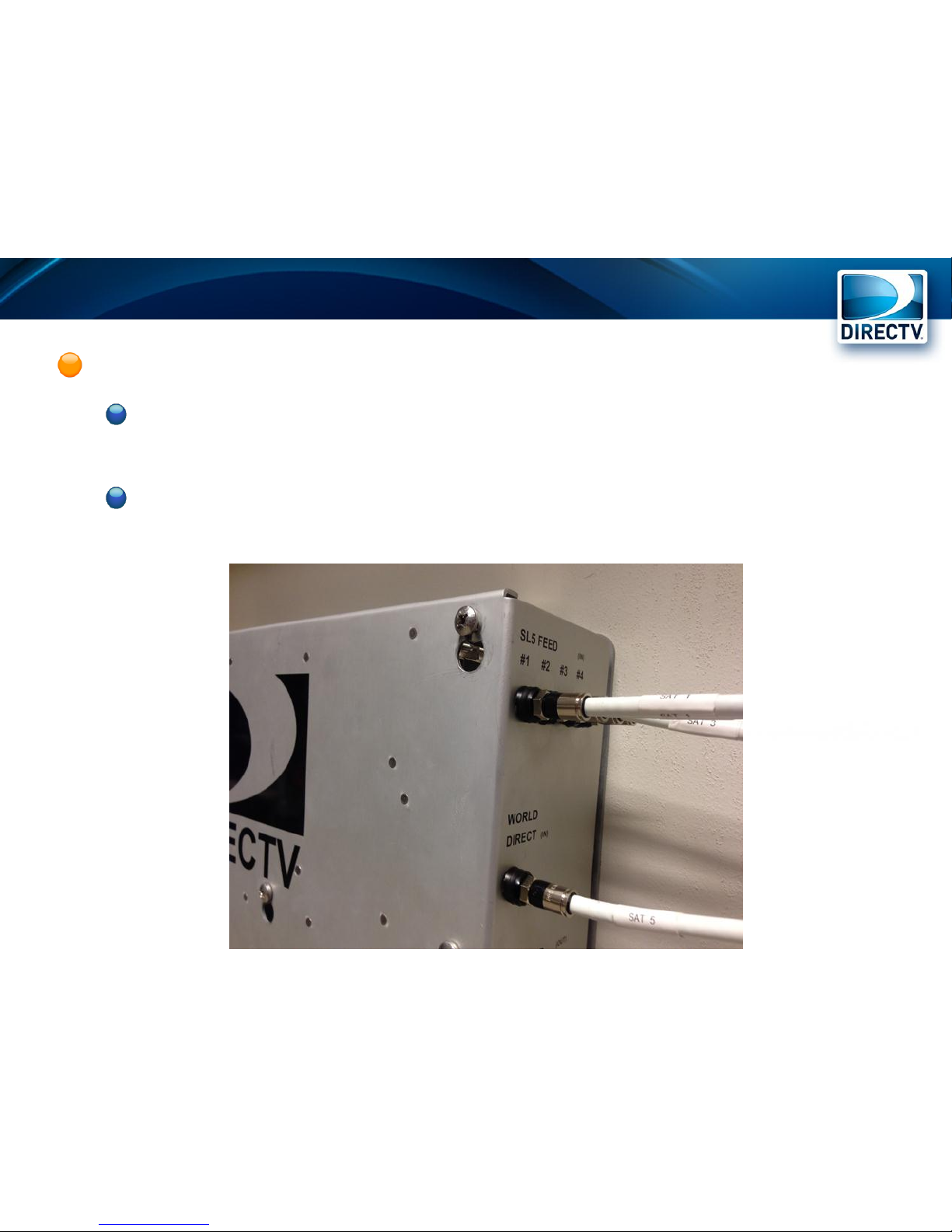
D2 Lite Enclosure Installation Continued
Connect from ODU(s) to enclosure
Slimline SL5 LNB coax cables are connected to the 4 SL5
FEED (IN) inputs
World Direct LNB coax cable is connected to the single
WORLD DIRECT (IN) input
Page 24
Installing in the Unit
Follows current DIRECTV approved residential
installation methods
Refer to the Standard Professional Installation Guidelines
(SPIG) for further information
Visit http://satinstalltraining.com for additional
information
Each unit will have a dedicated homerun to the
D2 Lite enclosure
D2 Lite is NOT intended to be used with shared services
(i.e. cable internet)
29V 1.4A being passed on the homerun line
If shared services are provided over coax the installation
operator is solely responsible for those shared services
Page 25
Installing in the Unit Continued
Homeruns should not exceed maximum cable
distance
RG6 should not exceed 150’
RG11 should not exceed 200’
Line amplifiers are NOT approved and will not be used
New homerun cabling should be installed
In the most direct route available between the enclosure
and the unit
Professionally
Properly attached to the building (where/when applicable)
Loose cabling should be tied together
Multiple homerun cables may be installed along the same cable path
Cables should be neatly bundled together
Zip ties should NOT be evenly spaced along the cable route
Maintain proper bend radius of the cable type installed
Page 26

Installing in the Unit Continued
Existing homerun cables may be used if
They are in good condition
RG6 or RG11 cable
RG59 should not be utilized
There are no splices/barrels existing in the cable run
Splices/barrels do not have to be installed to complete the
homerun cabling
Page 27

Installing in the Unit Continued
After the homerun cabling is in place,
before beginning the equipment
installation in the unit
Connect the homerun to the D2 Lite
enclosure
Use one of the available APMT FEED (OUT) ports
Ports 1, 2, 3, 4 are connected to SWiM16 #1
Ports 5, 6, 7, 8 are connected to SWiM16 #2
(when installed)
REMEMBER: the ports with the “*” have a
signal level 4.5dBm lower than the other
ports and should be connected to the
units with the shortest homerun lengths
All homeruns should be tagged at the D2
Lite enclosure to ensure easy
unit/homerun identification in the future
Page 28

Installing in the Unit Continued
The unit equipment install follows standard DIRECTV
installation practices
A PI-29 Power Inserter must be installed in every unit
The PI-29 provides the required voltage to the D2 Lite enclosure to power the
SWiM16 module(s)
2 and 4 way splitters may be installed in the unit
Properly terminate any open (unused) ports on the splitters
SWiM tuner count, for any single unit, cannot exceed 8 tuners
Any compatible SWiM receiver/device can be installed in the unit
All DIRECTV programming, services and national offers are available
to the customer
Note: Due to the unique design of the Holland splitters in the D2 Lite
enclosure up to 8 PI-29 power inserters can be connected to the D2 Lite
enclosure without causing an “overvoltage” or “power overload”
situation.
Page 29

D2 Lite Enclosure Testing
SWiM #1
In the unit
Run EIV+ at the SIGNAL TO IRD port on the power inserter
If EIV+ fails troubleshoot issue to resolution
At the D2 Lite enclosure
Run EIV+ at APMT FEEDs 2,3,4 (assumes APMT FEED 1 is connected to the homerun
and power inserter)
If EIV+ fails at any port, replace D2 Lite enclosure
DO NOT ATTEMPT TO REPLACE ANY COMPONENTS IN THE D2 Lite enclosure
SWiM #2 (if installed)
Same as SWiM #1 using APMT FEEDs 5,6,7,8
The D2 Lite enclosure needs be tested after it is installed and prior to
activating the first customer on each SWiM module. Testing should
take place after the homerun wiring is completed and the power
inserter is installed and powered on. These steps can also be used to
troubleshoot the D2 Lite system.
Page 30

ODU Removal
The removal of existing ODUs is a requirement of installing
D2 Lite
ODUs will be removed as customers are installed onto the
D2 Lite system
Removal of existing ODUs consists of:
Removing the LNB and LNB support arm
Removing the reflector
Removing the mount support arm
If a NPRM removal of the NPRM mount
ALWAYS LEAVE THE ODU FOOT AND MONOPOLE
FEET IN PLACE!!!!!
Removing the ODU foot and monopole feet can result in damage to
roof material and cause the area to leak
Proper disposal of all ODU materials
Subject to local laws and ordinances
Page 31

DIRECTV D2 Lite Inspections
Compliance inspections will be conducted on a
minimum of 25% of all D2 Lite installations.
Inspections are conducted by the Field Operations team
and local market QA inspectors.
Notification of the inspection will sent at least three (3)
business days in advance
The installation team is highly encouraged to attend the
inspection
Upon completion of the inspection the installation
team will be notified of the inspection results within
three (3) business days
Discrepancies found during the inspection are expected
to be resolved within five (5) days of notification
Page 32

DIRECTV D2 Lite Inspections Continued
Items of interest during the inspection, but not
limited to:
Proper installation of the ODU(s)
Proper grounding/bonding of the ODU and system
Proper installation of the D2 Lite enclosure
Proper service loop(s) installed at the D2 Lite enclosure
Cabling from the ODU to the D2 Lite enclosure
Homerun cabling: cabling from the D2 Lite enclosure to
the unit(s)
EIV+ tests will be run on an open port of the D2 Lite
enclosure when possible
At no time during the inspection will an active
customer be taken out of service
Page 33

D2 Lite Installation Diagrams V1 – 1 Receiver
Page 34

D2 Lite Installation Diagrams V1 – 2 Receivers
Page 35

D2 Lite Installation Diagrams V2 – 1 Receiver
Page 36
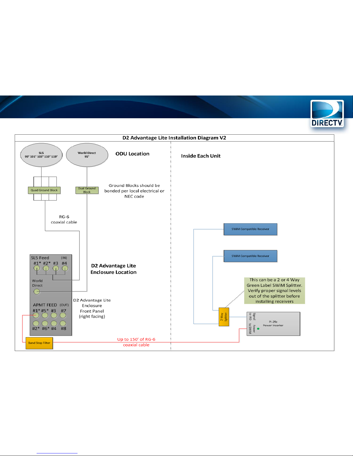
D2 Lite Installation Diagrams V2 – 2 Receivers
Page 37
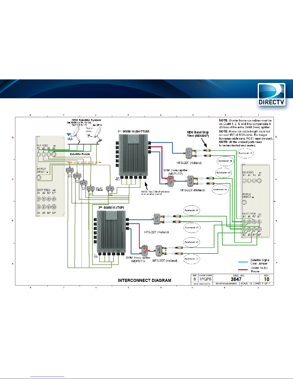
D2 Lite Electrical Interconnect Diagram V1
Page 38
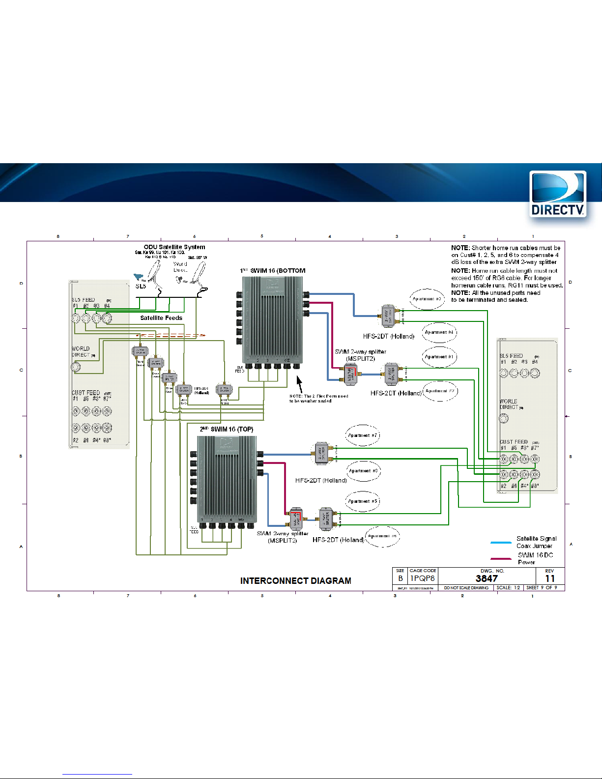
D2 Lite Electrical Interconnect Diagram V2
Page 39

References
Standard Professional Installation Guidelines (SPIG)
Available on the Dealer Website
http://satinstalltraining.com
Username: revolution
Password: training
DWS – Dealer Website
Distributor
Page 40

Q & A
Page 41

 Loading...