

Direct IP Network Camera Operation Manual

Network Camera
i
WARNING
RISK OF ELECTRIC SHOCK
DO NOT OPEN
WARNING: TO REDUCE THE RISK OF ELECTRIC SHOCK,
DO NOT REMOVE COVER (OR BACK).
NO USER-SERVICEABLE PARTS INSIDE.
REFER SERVICING TO QUALIFIED
SERVICE PERSONNEL.
COMPLIANCE NOTICE OF FCC:
THIS EQUIPMENT HAS BEEN TESTED AND FOUND TO COMPLY WITH THE LIMITS FOR A CLASS
A DIGITAL DEVICE, PURSUANT TO PART 15 OF THE FCC RULES. THESE LIMITS ARE DESIGNED
TO PROVIDE REASONABLE PROTECTION AGAINST HARMFUL INTERFERENCE WHEN THE
EQUIPMENT IS OPERATED IN A COMMERCIAL ENVIRONMENT. THIS EQUIPMENT GENERATES,
USES, AND CAN RADIATE RADIO FREQUENCY ENERGY AND IF NOT INSTALLED AND USED IN
ACCORDANCE WITH THE INSTRUCTION MANUAL, MAY CAUSE HARMFUL INTERFERENCE TO
RADIO COMMUNICATIONS. OPERATION OF THIS EQUIPMENT IN A RESIDENTIAL AREA IS
LIKELY TO CAUSE HARMFUL INTERFERENCE, IN WHICH CASE USERS WILL BE REQUIRED TO
CORRECT THE INTERFERENCE AT THEIR OWN EXPENSE.
WARNING: CHANGES OR MODIFICATIONS NOT EXPRESSLY APPROVED BY THE PARTY
RESPONSIBLE FOR COMPLIANCE COULD VOID THE USER’S AUTHORITY TO OPERATE THE
EQUIPMENT.
THIS CLASS OF DIGITAL APPARATUS MEETS ALL REQUIREMENTS OF THE CANADIAN
INTERFERENCE-CAUSING EQUIPMENT REGULATIONS.
The information in this manual is believed to be accurate as of the date of publication. We are not responsible for any
problems resulting from the use thereof. The information contained herein is subject to change without notice.
Revisions or new editions to this publication may be issued to incorporate such changes.
The software included in this product contains some Open Sources. You may obtain the complete
corresponding source code from us. See the Open Source Guide on the software CD (OpenSourceGuide\
OpenSourceGuide.pdf) or as a printed document included along with the User's Manual.
WEEE (Waste Electrical & Electronic Equipment)
Correct Disposal of This Product
(Applicable in the European Union and other European countries with separate collection systems)
This marking shown on the product or its literature, indicates that it should not be disposed with other household
wastes at the end of its working life. To prevent possible harm to the environment or human health from uncontrolled
waste disposal, please separate this from other types of wastes and recycle it responsibly to promote the sustainable
reuse of material resources.
Household users should contact either the retailer where they purchased this product, or their local government
office, for details of where and how they can take this item for environmentally safe recycling.
Business users should contact their supplier and check the terms and conditions of the purchase contract. This
product should not be mixed with other commercial wastes for disposal.

Operation Manual
ii
Important Safeguards
1. Read Instructions
All the safety and operating instructions should be read
before the appliance is operated.
2. Retain Instructions
The safety and operating instructions should be retained for
future reference.
3. Cleaning
Unplug this equipment from the wall outlet before cleaning
it. Do not use liquid aerosol cleaners. Use a damp soft cloth
for cleaning.
4. Attachments
Never add any attachments and/or equipment without the
approval of the manufacturer as such additions may result in
the risk of fire, electric shock or other personal injury.
5. Water and/or Moisture
Do not use this equipment near water or in contact with water.
6. Placing and Accessories
Do not place this equipment on an wall or ceiling that is not
strong enough to sustain the camera. The equipment may
fall, causing serious injury to a child or adult, and serious
damage to the equipment. Wall or shelf mounting should
follow the manufacturer's instructions, and should use a
mounting kit approved by the manufacturer.
This equipment and cart combination should be moved with
care. Quick stops, excessive force, and uneven surfaces
may cause the equipment and cart combination to overturn.
Do not place this equipment in an enclosed space. Sufficient
ventilation is required to prevent an increase in ambient
temperature which can cause malfunction or the risk of fire.
7. Power Sources
This equipment should be operated only from the type of
power source indicated on the marking label. If you are not
sure of the type of power, please consult your equipment
dealer or local power company.
8. Power Cord
Operator or installer must remove power and TNT connections
before handling the equipment.
9. Lightning
For added protection for this equipment during a lightning
storm, or when it is left unattended and unused for long
periods of time, unplug it from the wall outlet and disconnect
the antenna or cable system. This will prevent damage to
the equipment due to lightning and power-line surges. If
thunder or lightning is common where the equipment is
installed, use a surge protection device.
10. Overloading
Do not overload wall outlets and extension cords as this can
result in the risk of fire or electric shock.
11. Objects and Liquids
Never push objects of any kind through openings of this
equipment as they may touch dangerous voltage points or
short out parts that could result in a fire or electric shock.
Never spill liquid of any kind on the equipment.
12. Servicing
Do not attempt to service this equipment yourself. Refer all
servicing to qualified service personnel.
13. Damage requiring Service
Unplug this equipment from the wall outlet and refer
servicing to qualified service personnel under the following
conditions:
A. When the power-supply cord or the plug has been
damaged.
B. If liquid is spilled, or objects have hit the equipment.
C. If the equipment has been exposed to rain or water.
D. If the equipment does not operate normally by following
the operating instructions, adjust only those controls that
are covered by the operating instructions as an improper
adjustment of other controls may result in damage and
will often require extensive work by a qualified technician
to restore the equipment to its normal operation.
E. If the equipment has been dropped, or the cabinet damaged.
F. When the equipment exhibits a distinct change in
performance — this indicates a need for service.
14. Replacement Parts
When replacement parts are required, be sure the service
technician has used replacement parts specified by the
manufacturer or that have the same characteristics as the
original part. Unauthorized substitutions may result in fire,
electric shock or other hazards.
15. Safety Check
Upon completion of any service or repairs to this equipment,
ask the service technician to perform safety checks to determine
that the equipment is in proper operating condition.
16. Field Installation
This installation should be made by a qualified service person
and should conform to all local codes.
17. Correct Batteries
Warning: Risk of explosion if battery is replaced by an incorrect
type. Dispose of used batteries according to the instructions.
18. Tmra
A manufacturer’s maximum recommended ambient temperature
(Tmra) for the equipment must be specified so that the customer
and installer may determine a suitable maximum operating
environment for the equipment.

Network Camera
iii
Table of Contents
Chapter 1 — Introduction ............................................................................. 1
In This Manual .......................................................................................... 1
Features ................................................................................................... 1
Typical Applications ................................................................................. 2
With DirectIP
TM
NVR .......................................................................... 2
With Non-DirectIP
TM
NVR or Without NVR ......................................... 3
Chapter 2 — Installation............................................................................... 5
Package Contents .................................................................................... 5
Dimensions .............................................................................................. 5
Illustrated Parts List .................................................................................. 6
Indoor and Outdoor ............................................................................ 6
Flushed .............................................................................................. 7
Cable ........................................................................................................ 8
Factory Reset ........................................................................................... 9
Mounting ................................................................................................ 10
Chapter 3 — Remote Setup ....................................................................... 13
Camera Protocol .................................................................................... 13
Quick Setup ............................................................................................ 14
System ................................................................................................... 15
General ............................................................................................ 15
Date/Time ......................................................................................... 16
User/Group ....................................................................................... 17
Network .................................................................................................. 18
IP Address ........................................................................................ 18
FEN .................................................................................................. 19
Port/QoS .......................................................................................... 20
Bandwidth Control ............................................................................ 22
Security ............................................................................................ 23
IEEE 802.1X ..................................................................................... 24
Video ...................................................................................................... 25
Camera ............................................................................................ 25
Streaming ......................................................................................... 29
Webcasting ...................................................................................... 31
MAT .................................................................................................. 32
Privacy Masking ............................................................................... 33
PTZ .................................................................................................. 34
Audio ...................................................................................................... 41
Input/Output ..................................................................................... 42
Event Action ........................................................................................... 42

Operation Manual
iv
Alarm Out ......................................................................................... 43
Email ................................................................................................ 44
Remote Callback .............................................................................. 45
Audio Alarm ...................................................................................... 46
FTP Upload ...................................................................................... 47
Record .............................................................................................. 48
Event ...................................................................................................... 51
Alarm In ............................................................................................ 51
Motion Detection .............................................................................. 53
Trip-Zone .......................................................................................... 54
Audio Detection ................................................................................ 55
Tampering ........................................................................................ 57
System Event ................................................................................... 58
Chapter 4 — WebGuard ............................................................................ 59
Web Monitoring Mode ............................................................................ 61
Web Search Mode ................................................................................. 63
Appendix .................................................................................................... 65
Connector Pin Outs ................................................................................ 65
Troubleshooting ..................................................................................... 65
Map of Screens (Remote Setup) ............................................................ 66
Specifications ......................................................................................... 67
Index .......................................................................................................... 69

Network Camera
1
Chapter 1 — Introduction
In This Manual
This manual is intended for users of the network camera and includes instructions for using and
managing the camera on the network.
Features
This network camera compresses live video and transmits the video over Ethernet connections.
The camera can be accessed, configured and managed by using the INIT (Integrated Network
Installation Tool) program. It has a built-in web server, WebGuard, allowing you to monitor live
video and search recorded video remotely using a web browser. The remote programs provided
with the camera also allow remote management, monitoring, searching and recording. This camera
offers the following features:
Multistream for live monitoring and recording
H.264 and M-JPEG compression algorithm
Four levels of video compression and various video compression resolutions
Two-way audio communication
Pre- and post-event buffering and video stream buffering to enhance reliability of network recording
Remote monitoring via web browser or remote software
Automatic HTML code generation for webcasting on a user’s website
Up to 10 simultaneous connections to the camera for remote monitoring
Enhanced security using IP address filtering, HTTPS, SSL and IEEE 802.1X functions and
password protected multiple user levels
Network bandwidth limit and MAT functions to use network bandwidth efficiently
Convenient network connection using the UPnP (Universal Plug and Play) function and built-in
mDNS (Multicast DNS) protocol
Support of the ONVIF protocol (Core specification version 2.2.0)
Support of the DirectIP
TM
protocol
Digital WDR (Wide Dynamic Range) to adjust the image display in high contrast conditions
Slow shutter to reduce the minimum illumination requirements
Day and night functionality with the built-in IR-cut filter changer
Convenient firmware upgrades via the network connection
Firmware duplication and autorecovery functions to enhance system stability
Management of multiple cameras via Ethernet connections
Event detection functions: alarm-in, motion, trip-zone, audio, tampering
Micro SD memory recording to provide redundancy in case of network disconnection
Power sources: 12 VDC, 24 VAC, PoE (Power over Ethernet)
NTSC or PAL programmable video output
Optical zoom functionality with an optical zoom lens
Micro stepping motor for controlling a Pan/Tilt
Built-in heater allowing operation in a sub-zero temperature (only for heater supported model)
Operation Manual
2
IP66-level for water resistant protection and dustproof against rain and dust (not supported for
the flushed model)
NOTES:
In this manual, a “remote system” refers to a PC that the remote program (iNEX Basic or
WebGuard) is running.
Remote monitoring and recording through multistream are available by using the iNEX Basic
program provided with the camera.
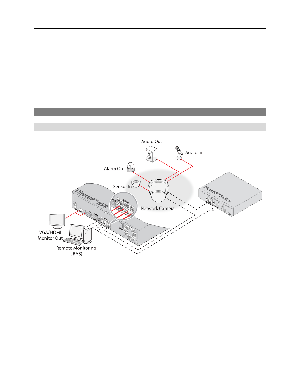
Typical Applications
With DirectIPTM NVR
NOTE: See the NVR operation manual for explanation about setting up the camera.
Network Camera
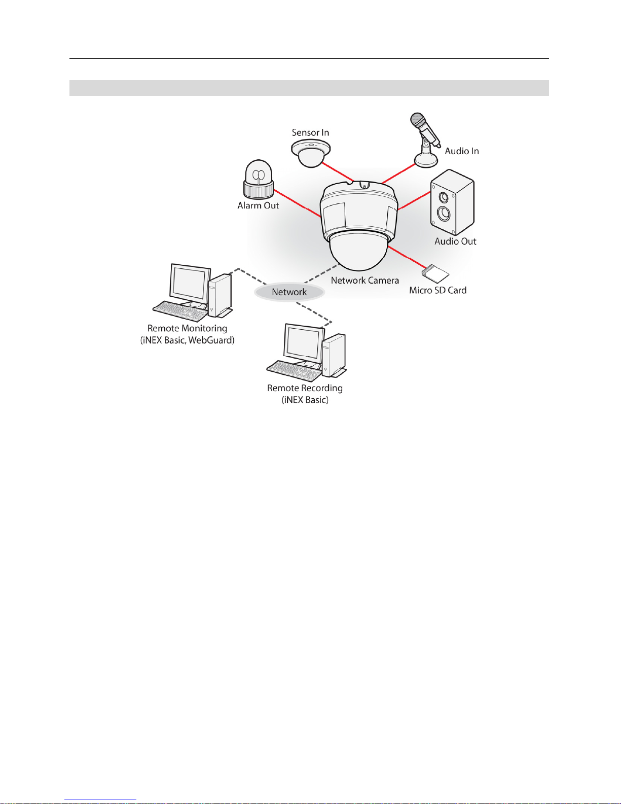
3
With Non-DirectIPTM NVR or Without NVR

Operation Manual
4
Network Camera
5
Chapter 2 — Installation
Package Contents
Network Camera
Installation CD (INIT/iNEX Basic software and operation manual)
Quick Guide
Mount Kits
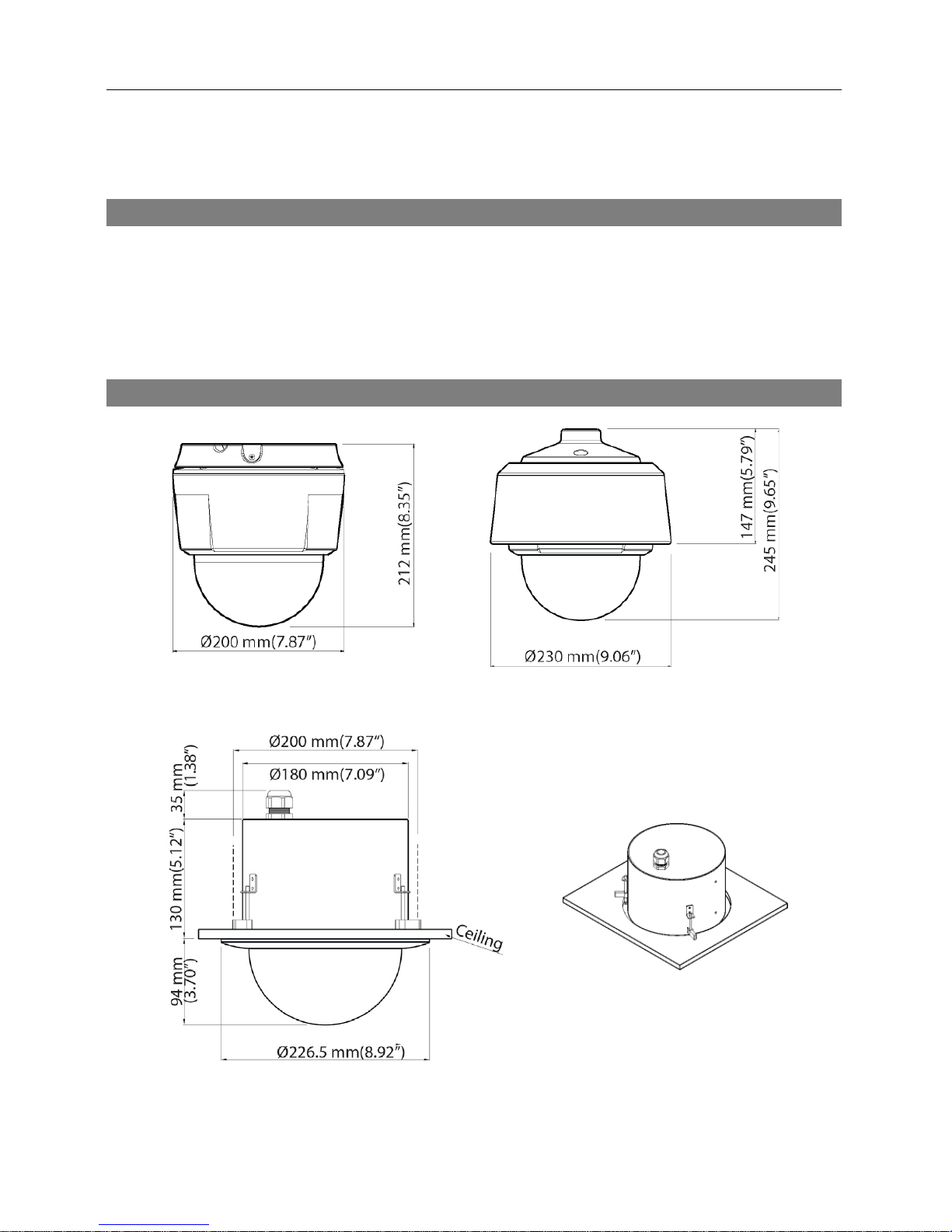
Dimensions
Indoor Outdoor
Flushed
Operation Manual
6
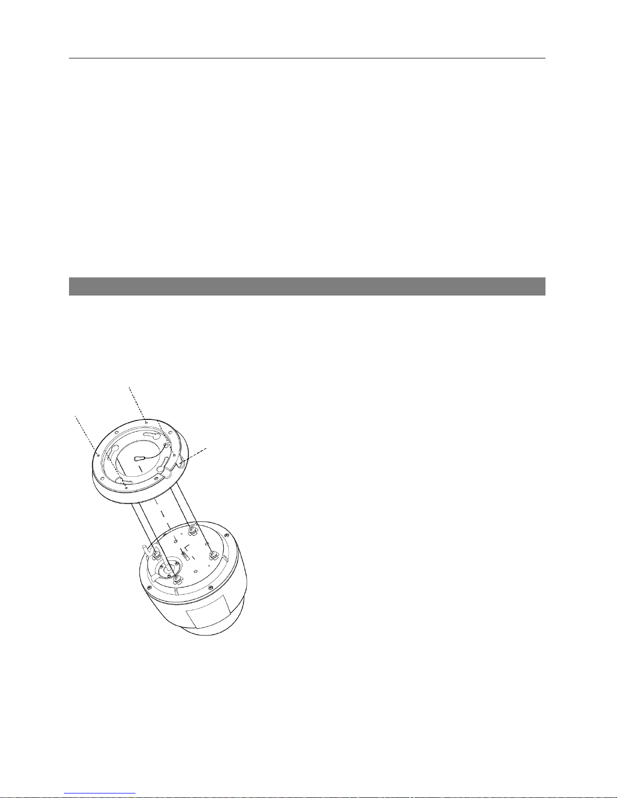
Illustrated Parts List
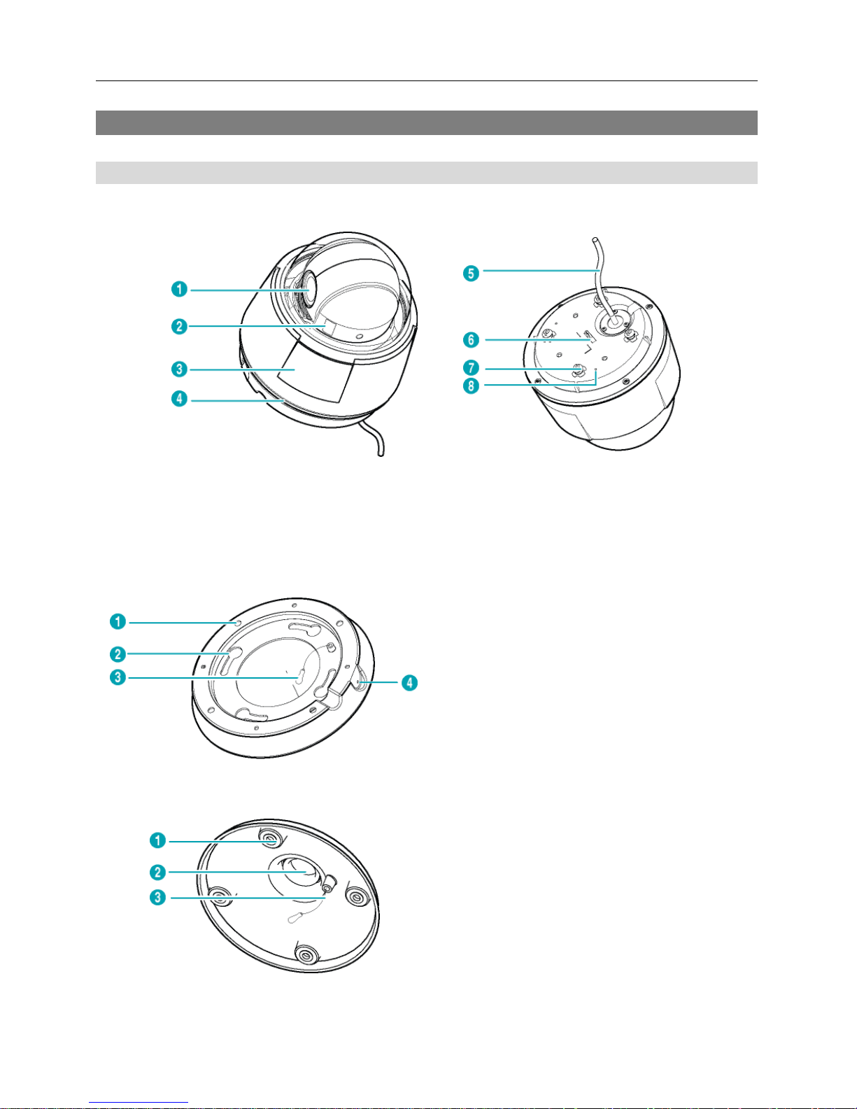
Indoor and Outdoor
< Body>< Bod
y –
Bottom Side View >
① Lens ② Micro SD Memory Card Slot ③ Dome Cover
④ Waterproof Sealing (black rubber) ⑤ Cable ⑥ Safety Wire Ring
⑦ Indoor Bracket Setscrew ⑧ Sun Shield Fastening Screw Hole
< Indoor Bracket >
① Wall/Ceiling Mounting Hole
② Indoor Bracket Setscrew Hole
③ Safety Wire
④ Indoor Bracket Fastening Screw Hole
< Outdoor Bracket* >
① Sun Shield Setscrew Hole
② Pipe Fastening Hole
③ Safety Wire
Network Camera
7
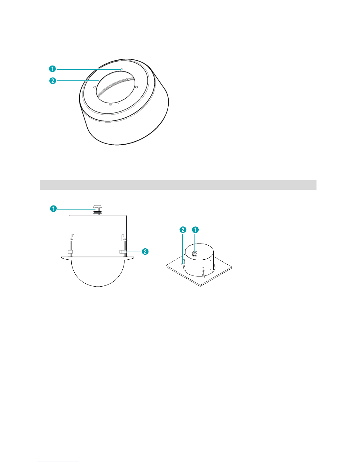
< Outdoor Sun Shield* >
① Outdoor Bracket Setscrew Hole
② Sun Shield Fastening Screw Hole
* The outdoor bracket and sun shield are purchased separately. Ask your dealer or distributor
about purchasing it.
Flushed
< Housing >
① Cable Grand
② Mounting Clamp
Lens: Optical zoom lens is installed.
Dome Cover: It protects the inner parts of the camera.
Waterproof Sealing: It resists the ingress of water.
Micro SD Memory Card Slot: Insert a micro SD memory card (SLC (Single Level Cell) or
MLC (Multi Level Cell) types of SanDisk or Transcend brands recommended). It is required
that you remove the dome cover to remove or insert a SD memory card. Make sure that the
waterproof sealing is joined properly when reconnecting the dome cover; otherwise, the IP66
level is not guaranteed.
Indoor Bracket Setscrew, Indoor Bracket Setscrew Hole: When installing an indoor camera,
it connects the body to the indoor bracket.
Indoor Bracket Fastening Setscrew, Indoor Bracket Fastening Setscrew Hole: When
installing an indoor camera, it fastens the body to the indoor bracket.
Safety Wire, Safety Wire Ring: Allows you to connect the body to a bracket or a bracket to
the body. It prevents the body or a bracket from falling when you separate the body from a
bracket or a bracket from the body.
Operation Manual
8
Cable Assembly: See below.
Wall/Ceiling Mounting Holes: Allows you to screw the camera to the wall or ceiling.
Sun Shield Setscrew Hole, Outdoor Bracket Setscrew Hole: When installing an outdoor
camera, it connects the outdoor bracket to the sun shield.
Sun Shield Fastening Screw Hole: When installing an outdoor camera, it fastens the sun
shield to the camera body by using the sun shield crew provided with the camera.
Outdoor Bracket Fastening Setscrew, Outdoor Bracket Fastening Setscrew Hole: When
installing an outdoor camera, it fastens the sun shield to the outdoor bracket.
Pipe Fastening Hole: When installing an outdoor camera, it fastens the pipe, which the cable
assembly goes through, to the outdoor bracket.
Cable Grand: Allows you to feed wires and cables for connection to power, devices, and
Ethernet.
Mounting Clamp: Allows you to fasten the camera to the ceiling.
CAUTIONS:
Make sure that the waterproof sealing is screwed to the dome cover tightly when
reconnecting the dome cover after removing it to remove or insert a SD memory
card or perform a factory reset. If the waterproof sealing is not joined to the dome
cover properly, the IP66 level is not guaranteed. Ask your dealer or distributor
for details.
Do NOT remove the SD memory card while the unit is operating; otherwise, the
system might not operate properly and recorded data saved on it might be damaged.
SD memory cards are expendable supplies. After a certain use in time, partial
memory sectors can be damaged and recording may not be available or data will
be lost. Check the SD memory card periodically and replace it with a new one
if necessary.
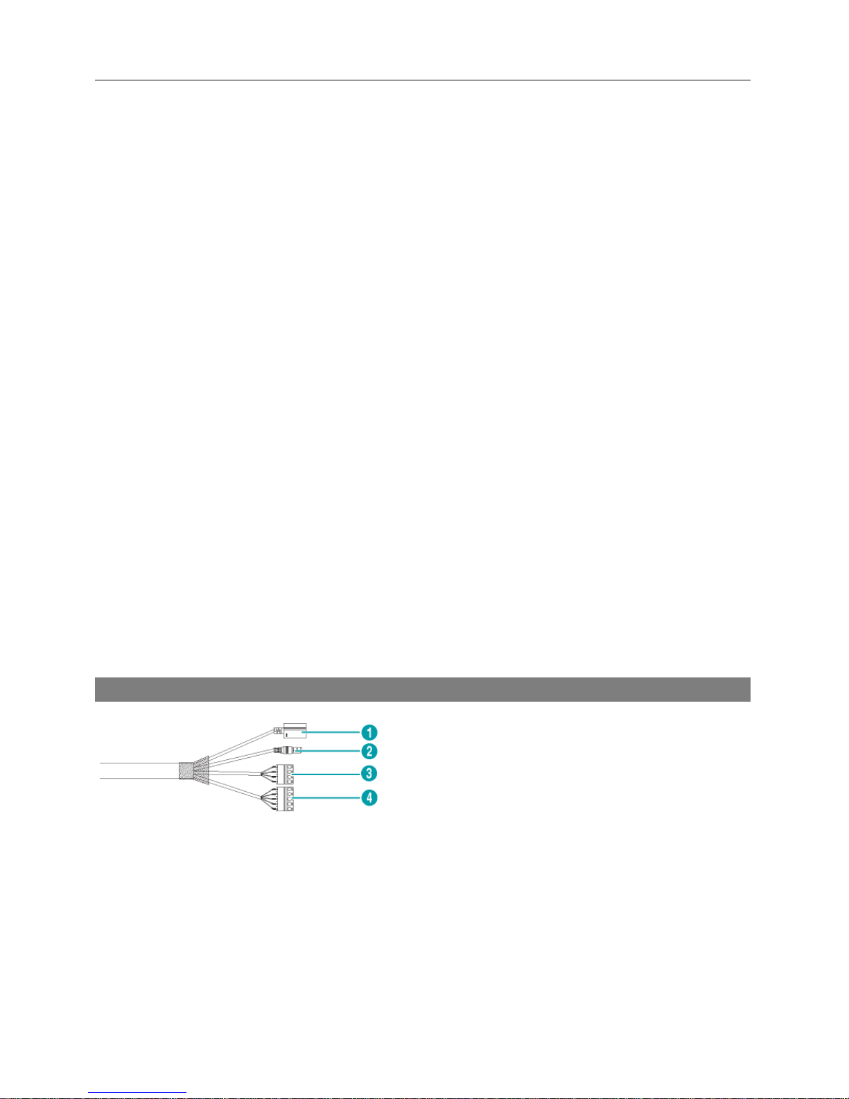
Cable
① Network Port
② Power
③ Alarm In/Out
④ Audio In/Out, Video Out
Network Port: Connect a Cat5 cable with an RJ-45 connector. You can change the settings,
manage the camera, upgrade the software or monitor video remotely via the network connection.
Refer to the INIT User’s Manual for details about network connection setup. When using a PoE
switch, the camera can be supplied with power over Ethernet cable (Refer to the PoE switch
manufacturer’s manual for details).
Power: Connect the power adapter.
Alarm In/Out

Network Camera
9
− ALI: Connect an alarm-in device. Mechanical or electrical switches can be wired to the IN
and GND (Ground) connectors. The voltage range is from 0V to 5V. When the electrical
switch is wired, the threshold voltage for NC (Normally Closed) is above 4.3V and for NO
(Normally Open) is below 0.3V, and it should be stable at least 0.5 seconds to be detected.
− NO: Connect an alarm-out device to the NO (Normally Open) and COM (Common) connectors.
NO is a relay output which sinks 0.3A @ 125 VAC and 1A @ 30 VDC.
Audio In/Out
− L_I: Connect to an audio source (Line-in).
− L_O: Connect to an amplifier (Line-out). The camera does not have amplified audio output,
so you will need a speaker with an amplifier.
Video Out
− V_O, GND: Connect two wires from the cable to the camera and the other connector from
the cable to a monitor. This is intended for video preview while adjusting the camera. Configure
the video signal (NTSC or PAL) for video output in Remote Setup (Video – Camera menu >
Miscellaneous tab).
NOTE: Camera and audio surveillance may be prohibited by laws that vary by region. Check
the laws in your area before using this product for surveillance purposes.
CAUTIONS:
The camera restarts after the power adaptor is disconnected from the camera
when switching the power source from 12 VDC to PoE.
The network connector is not designed to be connected directly with cable or
wire intended for outdoor use.
WARNING: ROUTE POWER CORDS SO THAT THEY ARE NOT A TRIPPING HAZARD.
MAKE CERTAIN THE POWER CORD WILL NOT BE PINCHED OR ABRADED BY
FURNITURE. DO NOT INSTALL POWER CORDS UNDER RUGS OR CARPET. USE
THE POWER CORD THAT HAS A GROUNDING PIN. IF YOUR POWER OUTLET DOES
NOT HAVE A GROUNDING PIN RECEPTACLE, DO NOT MODIFY THE PLUG. DO NOT
OVERLOAD THE CIRCUIT BY PLUGGING TOO MANY DEVICES INTO ONE CIRCUIT.
Factory Reset
This will only be used on the rare occasions that you want to return all the settings to the original
factory settings.
NOTE: The factory reset switch is inside of the camera. Ask your dealer or distributor for details.
CAUTION: When performing a Factory Reset, you will lose any settings you have
saved.
Operation Manual
10
Cut off the power from the camera → Remove the dome cover and poke a straightened paperclip
into the factory reset switch hole. → Turn on the power while holding the reset switch → Release
the switch in about 5 seconds after the power is applied → The camera resets to factory defaults
and restarts after completing the factory reset → Reconnect the dome cover.
CAUTION: Make sure that the waterproof sealing is joined properly when reconnecting
the dome cover; otherwise, the IP66 level is not guaranteed.
You can perform a factory reset while the camera is turned on by pressing the factory reset switch
and releasing the reset switch. A factory reset also can be performed remotely by running the INIT
program. The camera restarts after completing the factory reset. Refer to the INIT User’s Manual
for details on remote factory resetting.
Mounting
WARNING: You might need to reinforce the wall or ceiling. If the wall or ceiling is
not strong enough to support the camera, the camera might fall damaging the camera
or causing injuries.
< Indoor >
1. Screw the indoor bracket to the wall or ceiling by using
the mounting screws provided with the camera.
2. Hook the safety wire of the bracket on the safety wire
ring of the camera body.
3. Connect the external devices, network and power adapter.
4. Connect the camera body to the indoor bracket. Fix the
bracket setscrew of the camera body up to the bracket
setscrew hole and turn the camera body 25 degrees
clockwise.
5. Fasten the camera body to the bracket by tightening a
screw provided with the camera to the bracket fastening
screw hole of the bracket.
6. Apply power.
Network Camera
11
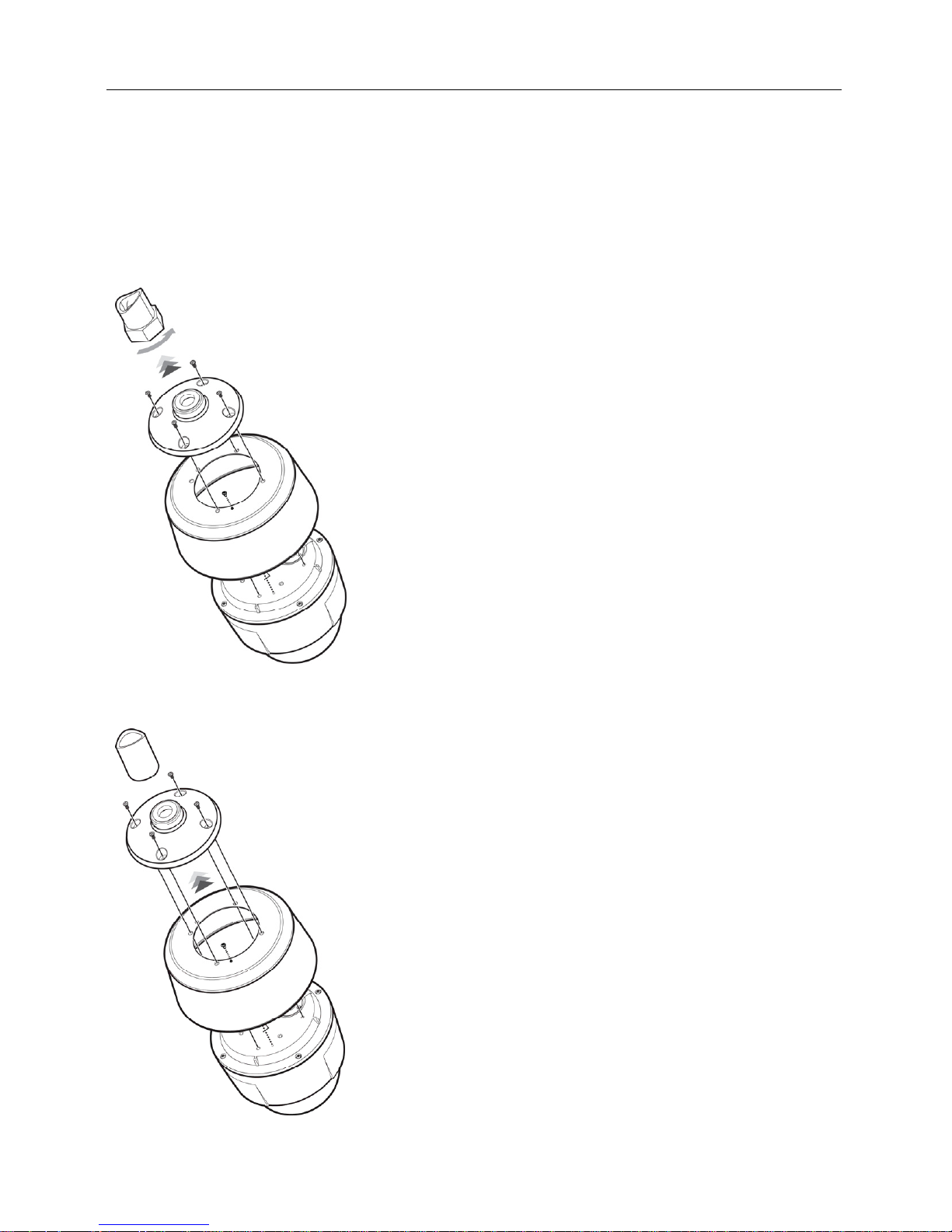
< Outdoor >
1. Remove the indoor bracket setscrew from the camera body.
2. Screw the sun shield to the camera body by using the sun shield setscrew provided with the
camera.
In case that a universal nut is attached to a pipe, connect the sun shield and outdoor bracket
first, then connect it to the pipe as follows:
3. Hook the safety wire of the outdoor bracket on the safety
wire ring of the camera body.
4. Screw the outdoor bracket to the sun shield by using the
setscrews provided with the camera.
5. Connect the cable from the camera to the pipe.
6. Connect the camera to the pipe by turning the universal nut.
7. Connect the external devices, network and power adapter.
8. Apply power.
CAUTION: Do not turn the camera but turn the
universal nut when connecting the camera to the
pipe, otherwise, the cable will be twisted.
In case that a universal nut is not attached to a pipe, connect the outdoor bracket to the pipe
first, then connect the sun shield to the outdoor bracket as follows:
3. Screw the outdoor bracket to the pipe by turning the outdoor
bracket.
4. Hook the safety wire of the outdoor bracket on the safety
wire ring of the camera body.
5. Connect the cable from the camera to the pipe.
6. Screw the sun shield to the outdoor bracket by using the
setscrews provided with the camera.
7. Connect the external devices, network and power adapter.
8. Apply power.
Operation Manual
12
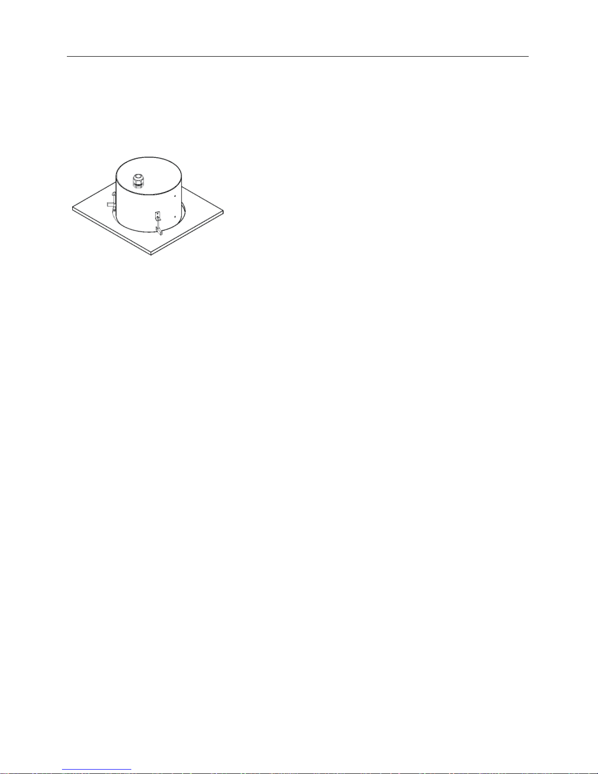
< Flushed >
The camera is mounted in the housing.
1. Remove the ceiling tile from the ceiling. Draw circle
whose diameter is 200 mm on the tile. Cut the circle
out of the ceiling tile.
2. Connect the external devices, network and power adapter.
3. Remove the housing dome cover from the housing can
by turning the housing dome cover counterclockwise.
4. Insert the housing into the ceiling and turn the screws
of three clamps clockwise. The clamps are laid over
the ceiling tile and the housing is held in the ceiling.
5. Connect the housing dome cover to the housing can
by turning the housing dome cover clockwise.
6. Apply power.
NOTE: The ceiling tile cannot be thicker than 1.3” (35mm).
Network Camera
13
Chapter 3 — Remote Setup
Remote Setup allows you to change all settings of a camera.
Camera Protocol
The camera supports DirectIP
TM
and Open protocols.
DirectIP
TM
Protocol:
− It enables connection to the camera without the need to configure network settings of the
camera by using with a DirectIP
TM
NVR.
− It allows you to change all settings of the camera directly from the DirectIP
TM
NVR, without
the need for a PC. See the NVR User’s Manual for details.
iNEX Protocol:
− It enables connection to the camera over the network from software installed on a PC or a
separate NVR if network settings of the camera are configured correctly.
− It is ideal when a DirectIP
TM
NVR is not available.
NOTE: Illustrations and descriptions in this manual refer to the Open protocol.
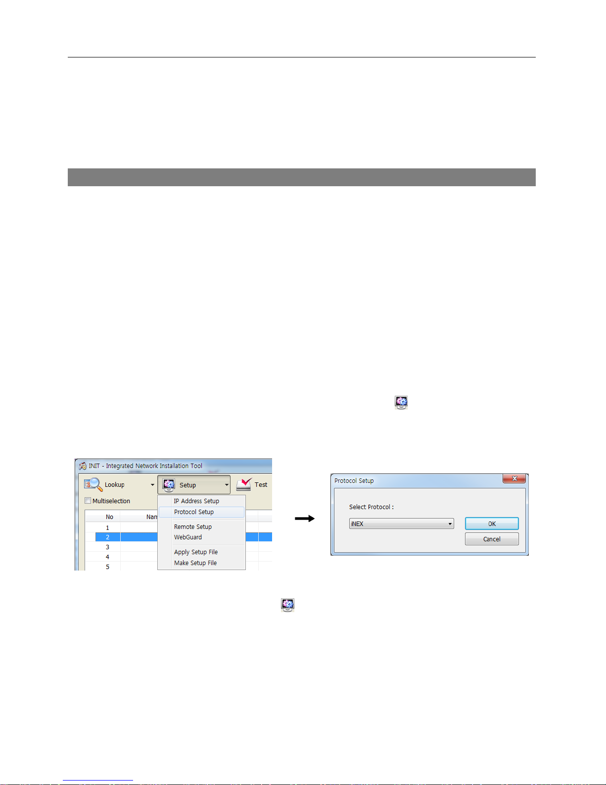
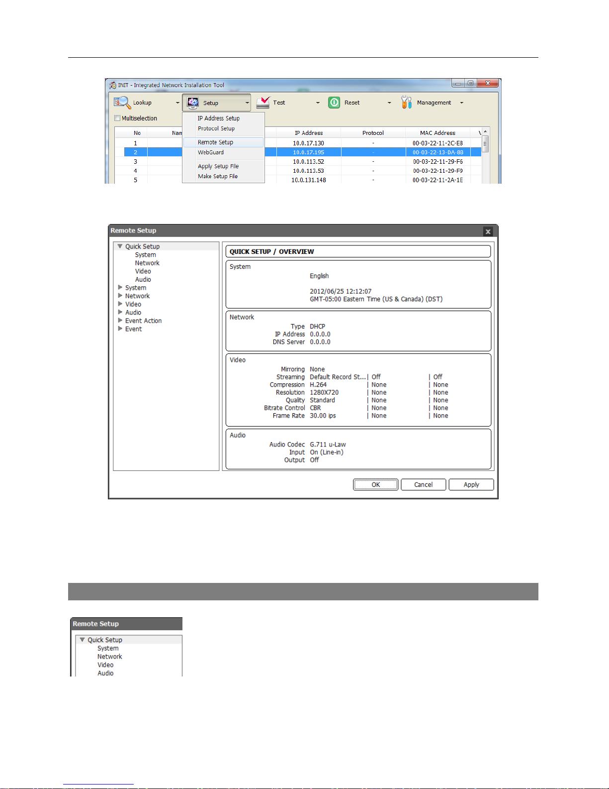
1. Run the INIT program, select a camera and click the Setup icon
on the Main screen.
2. Select Protocol Setup from the Setup menu and the Protocol Setup screen appears. You
can also display the Protocol Setup screen by selecting a camera, clicking the right mouse
button and selecting Protocol Setup on the Main screen.
3. Select iNEX.
4. Select a camera and click the Setup icon
on the Main screen → Select Remote Setup
from the Setup menu and the Remote Setup screen appears. You can also display the Remote
Setup screen by selecting a camera, clicking the right mouse button and selecting Remote
Setup on the Main screen.
Operation Manual
14
NOTE: You can also change the settings by using remote programs.
Clicking a menu on the left side of the Remote Setup screen displays the current settings for that
menu on the right side of the screen. Clicking a submenu under each menu allows you to change
the settings. Clicking the OK button closes the Remote Setup screen and applies the changes.
Quick Setup
The Quick Setup allows you to change a camera’s basic system, network,
video and audio settings.
Network Camera
15
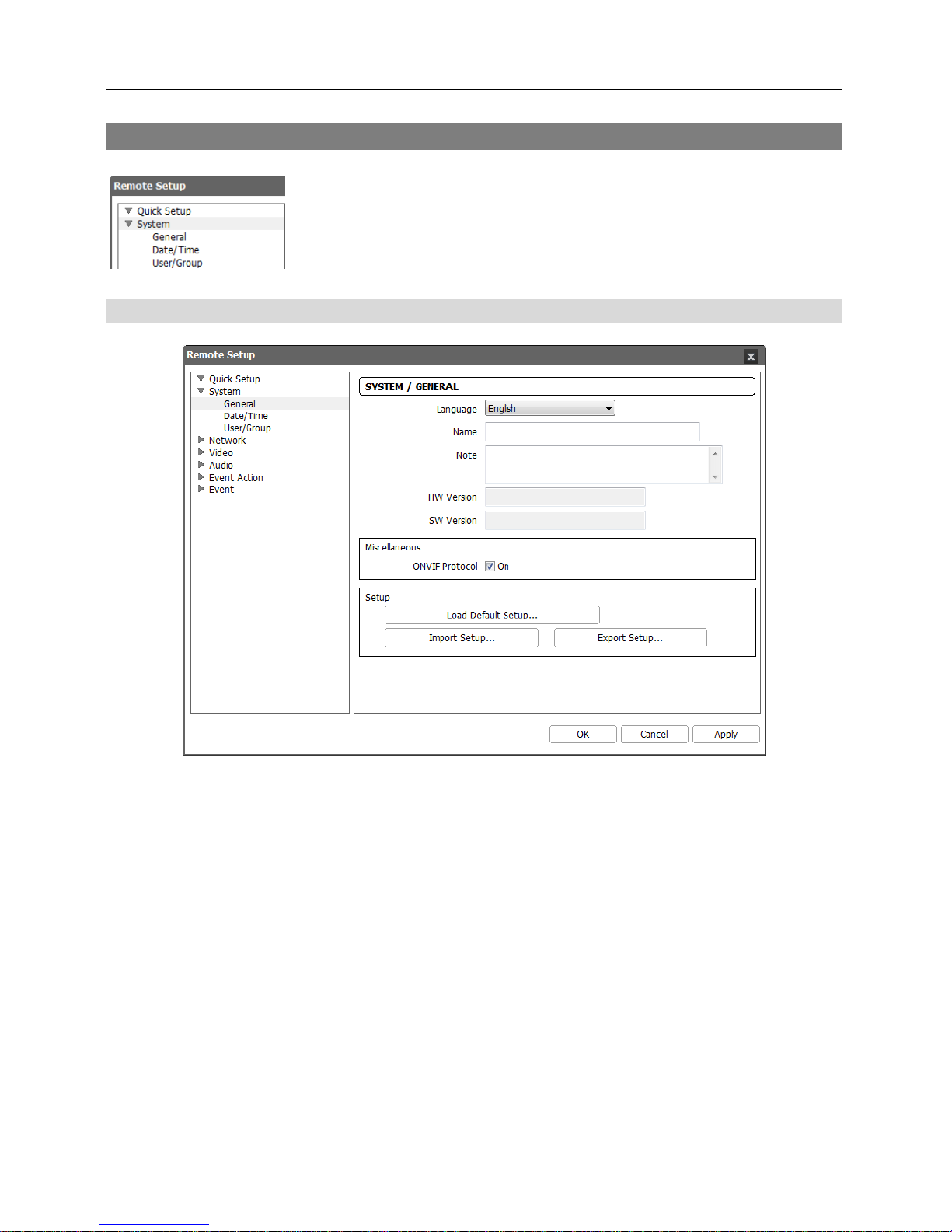
System
You can change a camera’s system information, import or export all
settings, and add users or groups.
General
Language: Choose the language to be used during remote setup.
Name: Enter the camera name (up to 31 characters including spaces).
Note: Enter additional information about the camera.
HW Version, SW Version: These fields display the camera’s hardware and software versions.
Miscellaneous:
− ONVIF Protocol: Check the box to enable the ONVIF protocol. The ONVIF protocol is available
only for users belonging to the default user groups (Administrator, Operator, User).
Setup:
− Load Default Setup…: Click to return all settings except date/time to the original factory
settings. You can select whether or not network settings will be included when the setup is
applied. Refer to the Network setup for details of the network settings.
− Import Setup…: Click to apply the settings saved as a .dat file format to the camera. A setup
screen appears allowing you to select the setup file. You can select whether or not to include
network settings (except FEN setting) when the setup is applied. Refer to the Network
setup for details of the network settings.
Operation Manual
16
− Export Setup…: Click to save the current camera settings as a .dat file format. A setup screen
appears allowing you to name the setup file.
NOTES:
The Load Default Setup and Import Setup functions are permitted only to the users in the
Administrator group.
Do NOT check the Include Network Setup box when the network settings of the setup file are
used in another camera. Otherwise, the connection to the camera might not be made properly.
If the IP address, admin port number or SSL settings are changed during Setup, Remote Setup
closes after saving the changes.
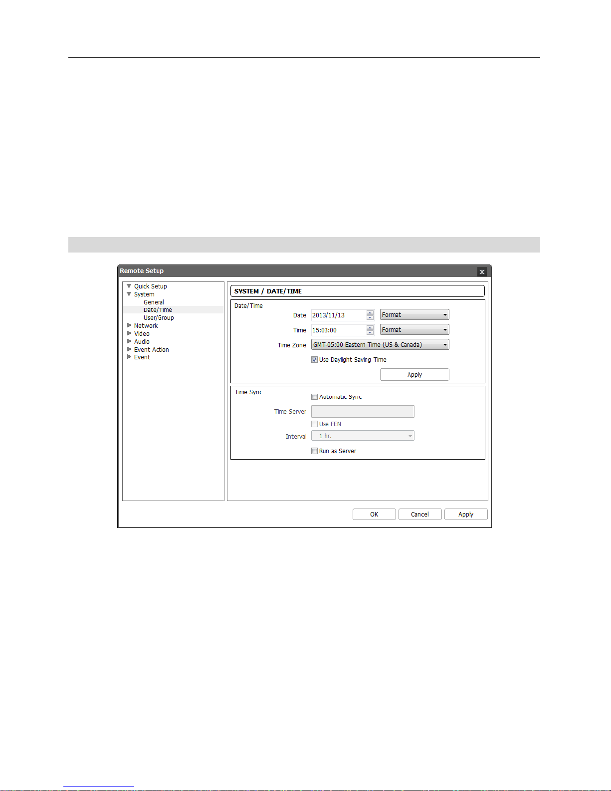
Date/Time
Date/Time: Change the system date/time, date/time format and time zone. Turn daylight-saving
time on or off by checking the box. Clicking the Apply button applies the changes immediately.
Time Sync
− Automatic Sync: Check the box to automatically synchronize the time with a time server. Enter
the IP address or the domain name of the time server and set the time interval for synchronization.
If the time server uses the FEN function, selecting the Use FEN box allows you to enter the
name instead of the IP address or the domain name of the time server.
− Run as Server: Check the box to run the camera as a time server.
NOTE: If you want to use a domain name instead of the IP address of the time server, the DNS
server must be set up properly when setting Network – IP Address setup. If you want to use a
name instead of the IP address or the domain name of the time server, the FEN function must
be set up properly when setting the Network – FEN setup.
Network Camera
17
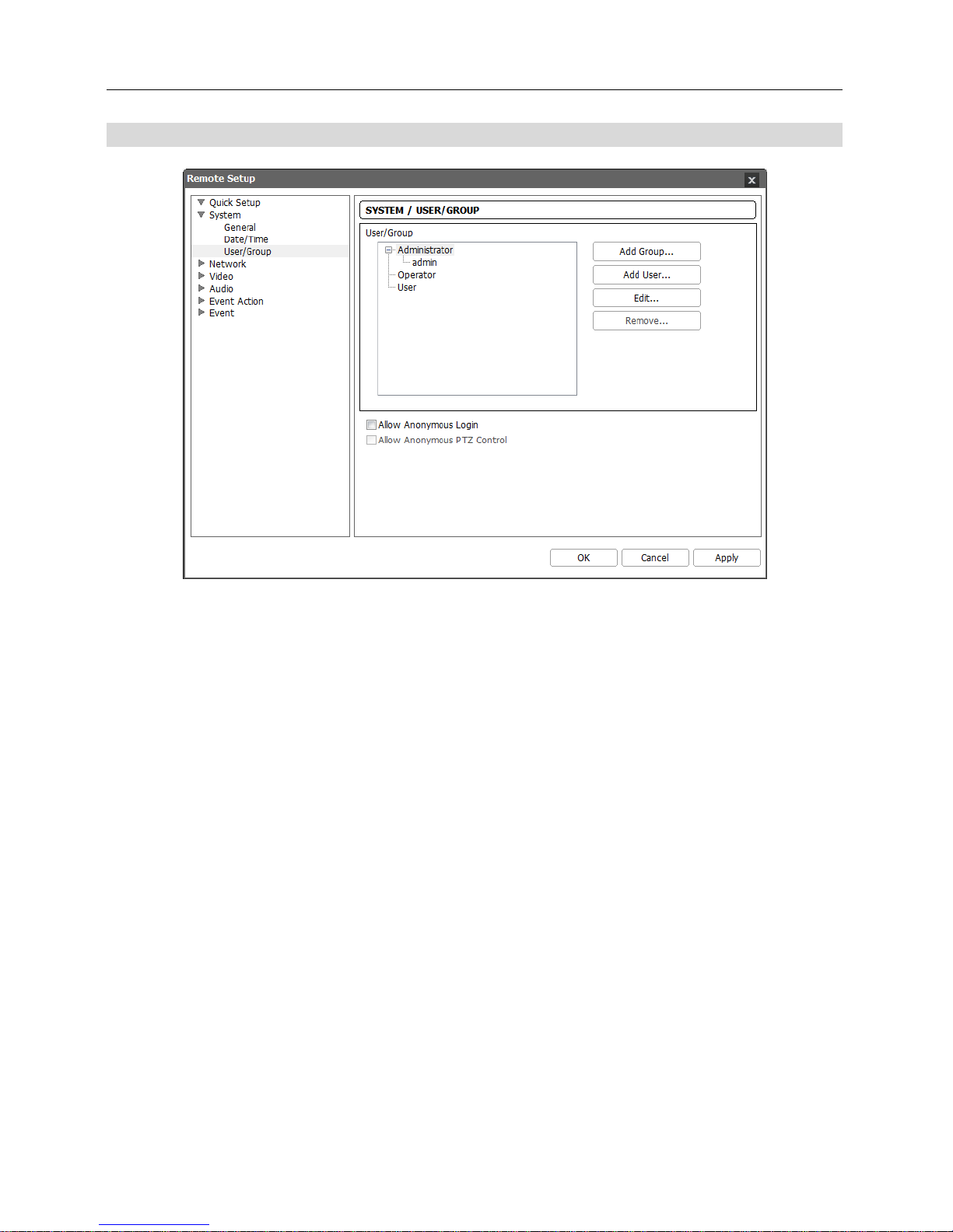
User/Group
User/Group: Click the buttons to change the settings for a group or a user allowed controlling
the camera remotely.
− Add Group: Click to add a group. Enter the group name and set authority levels for the group
to control the camera remotely.
− Add User: Click to add a user. Enter the user name and select the group that the user will
belong to. Enter the password to be assigned to the user.
− Edit: Select a group and click the button to change authority levels assigned to the group, or
select a user and click the button to change the user’s password.
− Remove: Select a group or user and click the button to delete the group or user.
Allow Anonymous Login: Check the box to use the webcasting feature. Refer to the Video –
Webcasting setup for details.
Allow Anonymous PTZ Control: Check the box to allow remote control of a PTZ on a website
by using the webcasting feature.
NOTES:
Only users belonging to the Administrator group can make User/Group changes.
There is no default password for the admin user in the Administrator group.
The default groups (Administrator, Operator, User) cannot be edited or deleted. The same
authority levels are assigned to the user groups in the ONVIF protocol.
The authority levels that can be assigned are:
– Upgrade: The user can upgrade the software.
– Setup: The user can set up the system.
– Color Control: The user can control brightness, contrast, hue and saturation for cameras.
– PTZ Control: The user can control pan, tilt and zoom of the camera.
 Loading...