

Directions VTU010 Setup Manual

VTU010 Setup
Guide
© 2011 ... Directions Ltd
Vehicle Tracking quick start guide2
Dear Customer,
Thank you for purchasing VTU10 Tracking Unit…
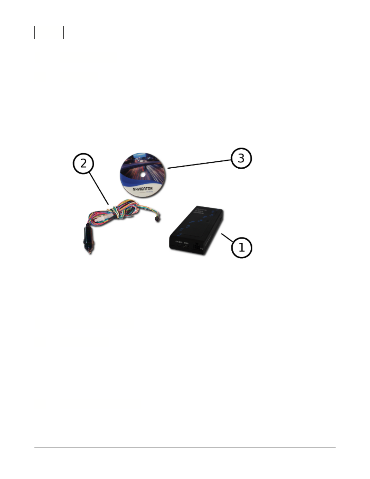
What is included in the pack:
1.
VTU10 unit
2.
Power lead
3.
VT Software CD
We recommend that electrical installation is performed by qualified persons.
Electrical installation must be performed carefully after checking the input voltage. All electric wires must be
properly insulated
. All unused wires must also be properly insulated and if no future use is
foreseen
then they
can be cut shorter. Secure the lead and leftover wires so that they are not loose, but take care not to damage
the insulation.
Do not place the battery the wrong way round.
Before you start with hardware installation, you will need to insert a SIM card first.
If this has been done by
your supplier, please skip this chapter.
1 Introduction
1.1 Welcome
2 Before you start
2.1 Precautions
2.2 Inserting a SIM card
© 2011 ... Directions Ltd
Before you start 3
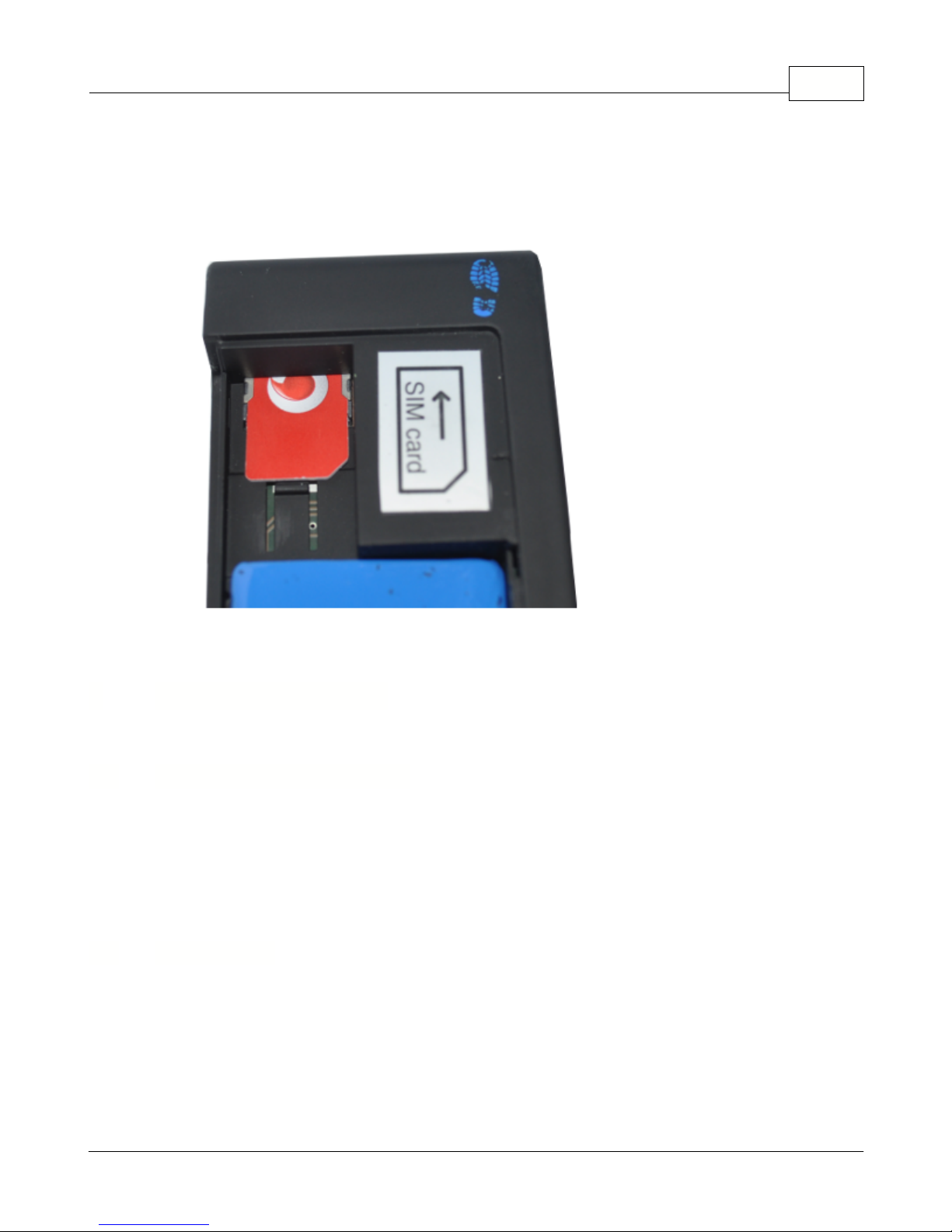
1)
Inserting the SIM card
a)make sure that the unit is disconnected from the electrical supply
b)
make sure that the PIN number is either disabled or set to 0000. This is most easily done using a mobile
phone.
c)insert your SIM as per picture below
There are two ways to connect the unit
Make sure the vehicle is turned off.
Push the cigarette lighter plug in to your vehicle's cigarette lighter socket. If your vehicle has a 12V power supply
(usually found in the boot) use that instead. Please remember that cigarette lighter sockets usually switch off
when the ignition is off cutting the electrical supply to the tracking unit. It can take several minutes to start
receiving GPS signal when ignition is turned back on, so you may loose the start of your journey.
We recommend that electrical installation is performed by a qualified auto-electrical engineer.
Electrical installation must be performed carefully after checking the input voltage. All
electric wires must be properly insulated. All unused wires must also be properly insulated
and if no future use is foreseen then they can be cut shorter. Secure the lead and leftover wires
so that they are not loose, but take care not to damage the insulation.
3 Connecting the unit
3.1 Cigarette lighter adaptor
3.2 Connection
© 2011 ... Directions Ltd
Vehicle Tracking quick start guide4
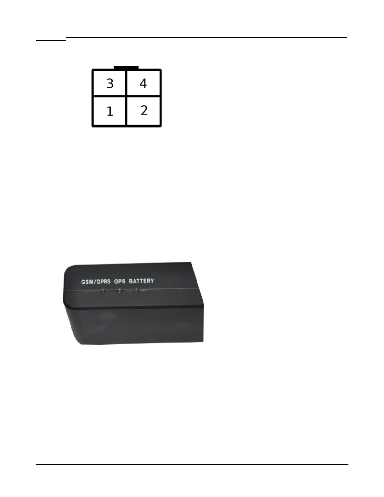
MOLEX 4 Connector
Overview of the power connector:
pin
colour
description
1
yellow
Binary input
22blue
ground – car chassis
3
red
+12V (if not using relay then input voltage can be between +8 and 26)
4
white
Binary input
1
The VTU009 comes with four LED indicators.
1. Red - battery status.
the led flashes more quickly as the battery discharges.
2. Green - GPS status
constantly on when GPS has fix
flashes when GPS has no fix
off when GPS is switched off in sleep mode
3. Yellow - GSM/GPRS status
off when the modem is turned off (e.g. sleep mode)
flashes quickly when not connected to a GSM network (once every 1 second)
flashes slowly when connected to a GSM network (once every 3 seconds)
on when connected to GPRS network
3.3 LED's
© 2011 ... Directions Ltd

4 Setting up a tracking unit
Use the MapExplorer to change the settings on the unit - including recording intervals, power saving
and GPRS parameters. Map Explorer can communicate with a tracking unit in three different ways –
serial cable (COM), GSM (modem), GPRS (TCP/IP). You can also change many settings without using
Map Explorer by sending SMS messages.
A) S
etting by SMS
GPRS communication can be changed be SMS:
Setapn apn username password
Note that all commands are case sensitive and the first character must be in upper case.
If your operator does not use username and password verification then send the word
null
.
For example for Orange send and SMS to the phone number for the SIM in the tracker:
Set_apn orangeinternet null null
Note:
Verify your APN settings with your provider as they vary between operators and even different contract
types.
Other SMS commands:
SMS Text
Action
Locate
- returns and SMS with the current location of the tracker in Lat/Long
Info- returns information about the tracker including serial number, firmware version and
status
Endgprs
- permanently disconnects the GPRS connection
G
prs- one time GPRS connection that updates all the history on the server and then
disconnects - useful for minimising charges when in roaming mode
G
prs
1 - allows GPRS roaming
G
prs
0 - prohibits GPRS roaming
Out1on
-
activate output
1
Out1off
- deactivate output
1
Reset
-
reset unit
SMS commands are case sensitive.
If the tracking unit is currently communicating over GPRS it may take longer to receive an SMS reply.
B) Communication over cable
In the MapExplorer menu select
Tracking/Communication device/COM Port
. The baud rate is typically
9600baud/s. This speed can be set in
Tools/Settings/Tracking/COM
.
To set the unit right click on the vehicle in the list and select unit settings.
C) Communication over GSM data
For this to work your computer must be connected to a GSM or analogue modem which does not
come as part of the package and must be obtained separately. In the MapExplorer menu select
Tracking/Communication device/Modem
. In order to connect successfully you must enter a valid GSM
data number in the vehicle properties.
To set the unit right click on the vehicle in the list and select unit
settings.
D) Communicating over GPRS (TCP/IP)
If you have not already done so then enable GPRS communication on the unit using the SMS
command above or by setting it over cable first. APN settings cannot be changed over
GPRS.
To set the unit right click on the vehicle in the list and select unit settings. In the
GPRS Access
Setting up a tracking unit 5
© 2011 ... Directions Ltd
Vehicle Tracking quick start guide6
Point
section fill in the APN details for you operator and then tick the
GPRS enabled
check box in the
Sending data packets to GPRS Server
section.
Now click
Send settings
.
Warning!
Sending GPRS data when abroad (roaming) can be expensive.
To learn more about how to use the MapExplorer software read the manual on the DVD. It can be
found in the
/manuals/Map Explorer
folder.
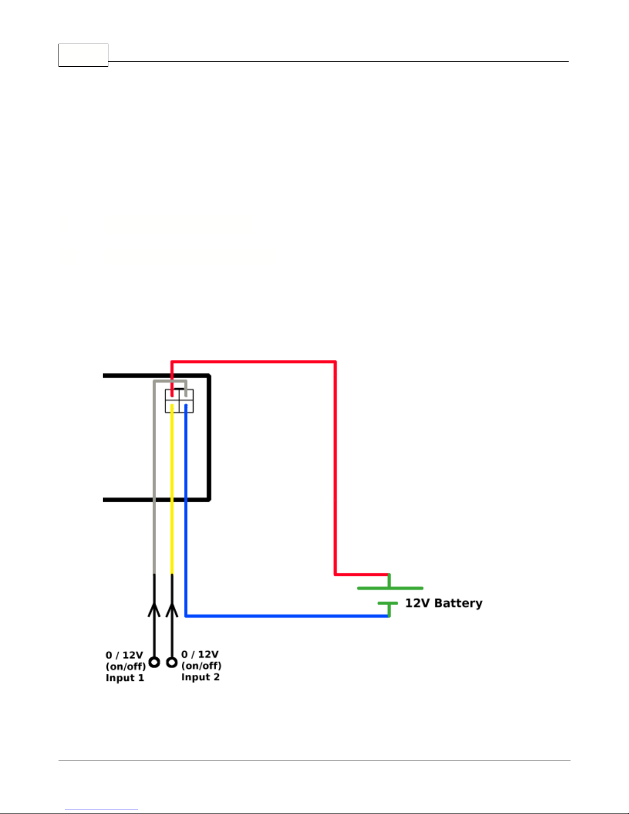
Connect binary inputs according to the scheme:
5 Inputs and Outputs
5.1 Connecting binary inputs
© 2011 ... Directions Ltd
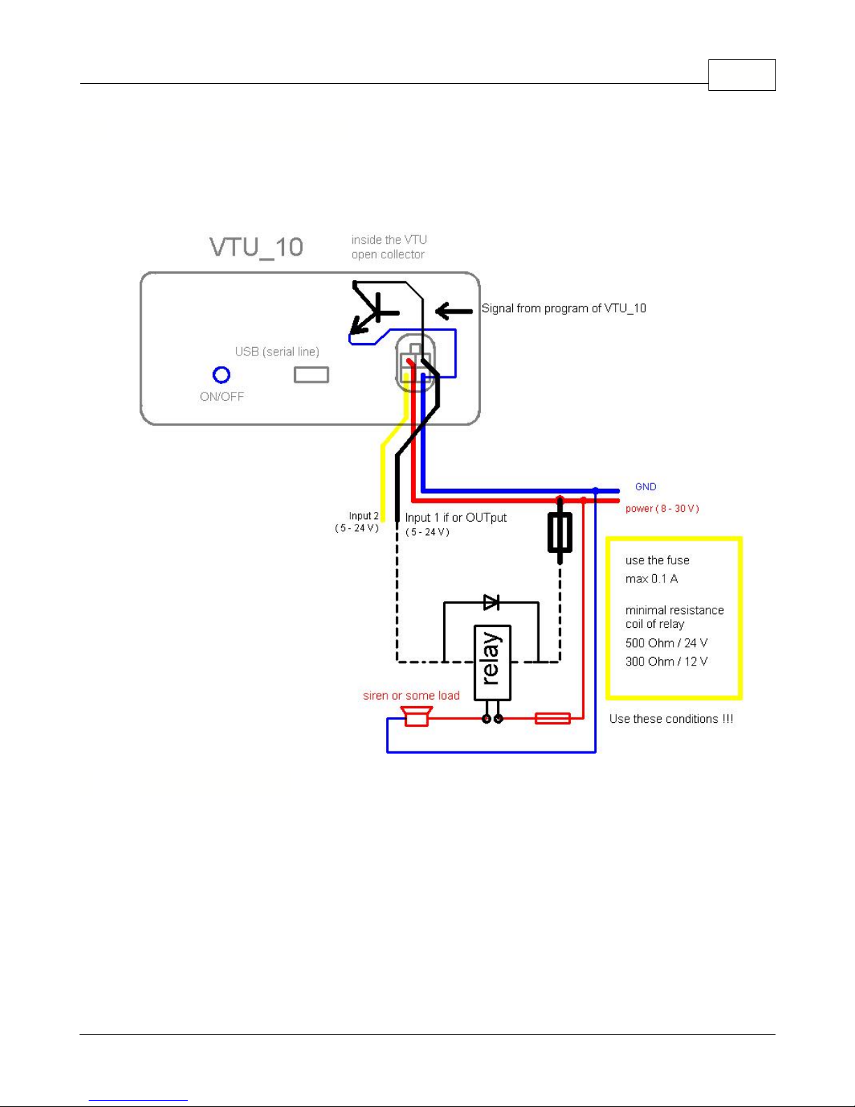
5.2 Connecting the output
Input 1 also doubles up as an output.
Warning: Only use this output with a relay, never direct to a load!!
Specifications
:
Power
DC 8 to 26 V
Power consumption (average)
125 mA / 12V
Power consumption in sleep-mode
20 mA / 12V
Motion sensor
Flash memory
100,000 positions,
GSM specifications:
GSM dual band modem
900/1800 MHz
GSM Circuit Switched Data
up to 14.4 kbps
Inputs and Outputs 7
6 Specifications
© 2011 ... Directions Ltd

Vehicle Tracking quick start guide8
Antenna Type
Built in tri band antenna
GPS specifications:
Channels
50 parallel
Digital input (protected) / Digital output (1A)
2
Dimension
123 x 50 x 20 mm
Operating Temperature
-20 to +65o C
Operation Humidity
95%,NO Condensing
Run SETUP.EXE from the installation CD and follow the on-screen instructions.
After enetering your serial number select to install MapExplorer.
The default language is selected according to settings in Windows (Start/Settings/Control
Panel/Regional and language options). You can change the language in Navigator in Settings.
Currently available languages are English, Czech, German and Italian.
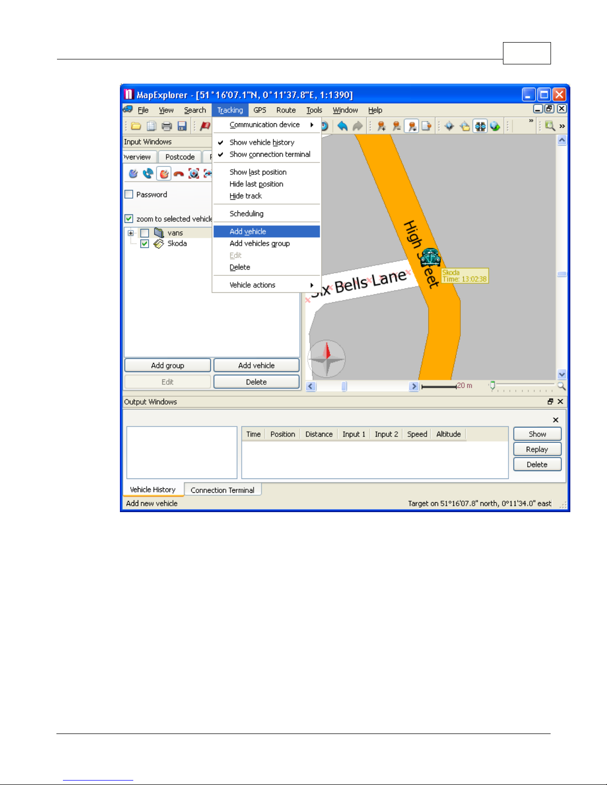
From the menu select
Tracking / Add vehicle or Add group
. Alternatively, you can right click on a
group in the list and select
Vehicles / Edit /Add vehicle
to add a vehicle into that group.
7 Software Installation
7.1 Adding a new Vehicle or Group
© 2011 ... Directions Ltd
Software Installation 9
You can also manage your vehicles using the buttons located at the bottom of the
Vehicles
tab.
When you add a new vehicle will see the
Vehicle properties
dialog:
© 2011 ... Directions Ltd
 Loading...