

Direct Healthcare Services Dyna-Form Air Pro-Plus User Manual

User Manual
DIRECTHEALTHCARESERVICES.CO.UK
DIRECTHEALTHCARESERVICES.CO.UK
2
DYNA-FORM AIR PRO-PLUS
The Dyna-Form Air Pro-Plus is a pressure relieving mattress suitable for use with patients at VERY HIGH RISK
of pressure ulcer damage.
Offering high levels of patient comfort, this mattress is particularly beneficial for use within the patient’s home or acute care
environment. A higher maximum weight capacity, up to 28 stone / 180kg, allows the product to meet the modern challenges
of those heavier clients. All component parts are interchangeable and replaceable, maximising product life and reducing
environmental impact.

DIRECTHEALTHCARESERVICES.CO.UK
USER MANUAL
3
Before operating this medical equipment, it is important to read this manual and understand the operating instructions and safety
precautions. Failure to do so could result in patient injury and/or damage to the product.
If you have any questions, please see contact information on cover.
1. Safety Precautions ............................................................................................................................................................4
2. Product Overview .............................................................................................................................................................5
Installation .......................................................................................................................................................................6
Unpacking & Inspection ....................................................................................................................................................6
3. Operation .........................................................................................................................................................................7
Control Unit Panel .............................................................................................................................................................7
Audible Warning Functions ................................................................................................................................................8
Mattress Function ............................................................................................................................................................8
Removal & Transport Function .........................................................................................................................................10
4. Troubleshooting .............................................................................................................................................................11
5. Cleaning ........................................................................................................................................................................13
6. Maintenance ..................................................................................................................................................................15
7. Warranty Information .......................................................................................................................................................16
8. Technical Specifications ..................................................................................................................................................18
Contents
Important Notice
NO SMOKING
DO NOT USE
PHENOL
DO NOT DRY CLEAN
TYPE BF
APPLIED PART
DO NOT DISPOSE OF
WITH HOUSEHOLD WASTE.
PLEASE REFER TO DHS WEBSITE
CAUTION
TEMPERATURE
LIMITATION
Dyna-Form Air Pro-Plus
This box contains an assembled mattress
system containing a:
A. Dyna-Form Air Pro-Plus Alternating Mattress
Replacement System
B. Digital Control Unit
C. Power Cord
D. Carry Bag
E. Instructions for Use
A
B
C D E

DIRECTHEALTHCARESERVICES.CO.UK
4
DYNA-FORM AIR PRO-PLUS
1. Safety Precautions
In General
Do not use this equipment in the presence of flammable anaesthetics. Explosions could result. In line with MDA/2013/073 the
manufacturer warns against the dangers of smoking in bed.
Bed frames used with the systems can vary greatly depending on the specific health care setting (i.e. hospitals, nursing homes, home
care, etc). It is the responsibility of the caregiver to take the necessary precautions to ensure the safety of the patient. This includes, but
is not limited to, the appropriate use of side rails to prevent falls and/or patient entrapment.
Minimize articles between the system surface and patient, and secure bed sheets loosely so as not to affect the alternating cell
movement.
The manufacturer does not require such preventive inspections by other persons.
The user must check that the equipment functions safely and see that it is in proper working condition before being used.
No special skills or training of the operator is required, there is no restriction on location or environment.
Significant risks of reciprocal interference may be posed by the presence of the system during specific investigations or treatments.
Potential electromagnetic or other interference between the system and other device may occur. If interference is suspected, move
equipment from sensitive devices or contact the manufacturer.
Preventive inspection and calibration is not required.
Do not modify this equipment without authorization of the manufacturer.
Manufacturer will provide circuit diagrams, component part lists, descriptions to assist to service personnel in parts repair.
The mattress is treated as the applied part.
Unplug the control unit from the mains power supply to disconnect the power.
Control Unit
The control unit is tested and approved according to ISO-EN 60601-1 rev.2 & EMC
Only plug into a grounded power receptacle and use the power cord supplied with the system.
Exposure of the electronic Control Unit to any liquid while it is plugged in could result in a severe electrical hazard.
Only use fuses that have the same specified rating. Using fuses with higher ratings could result in damage and/or injury.
(See Technical Specifications on cover).
The electronic Control Unit is a precision electronic product. Use care when handling or transporting. Dropping or other sudden
impacts may result in damage to the unit.
Do not open the Control Unit – risk of electrical shock. Do not attempt to repair or service the Control Unit. Repairs and service
should be conducted by an authorised local distributor. (See contact information on cover). If the Control Unit is not functioning properly,
or has been damaged, unplug the unit and take it out of service immediately. (See contact information on cover for repair and service
information).
Do not place any objects or items, such as blankets, on or over the Control Unit.
The power cord to the Control Unit should be positioned to avoid a tripping hazard and/or damage to the cord. It is recommended to
place the cord under the bed frame and attach it to an electrical outlet by the head of the bed.
Do not position the system so that it is difficult to operate the disconnection device.

DIRECTHEALTHCARESERVICES.CO.UK
USER MANUAL
5
2. Product Overview
Alternating Mattress system (see cover)
Dyna-Form Air Pro-Plus is an Alternating Mattress Replacement System providing pressure application and release to patients with,
or vulnerable to, pressure ulcers. It is designed to replace an existing mattress and can be used on both standard and profiling bed
frames.
Mattress
This system includes a static head cell(s) to provide static “pillow” support for optimum user comfort, while air pressure in the other
cells is alternated over a 10 minute cycle. This provides regular periods of pressure reduction to aid blood and lymphatic flow to
vulnerable tissue.
Control unit
The Control unit provides the air supply to the Mattress.
• It is controlled via a touch panel with integrated digital display. The Audible Warning sounds when pressure fails or power is
interrupted. Audible Warning Mute silences the Audible Warning for maximum of 20 minutes – the Audible Warning resumes if
cause of failure is not resolved. The Audible Warning will sound for up to two hours following an interruption to power.
• The Control Unit includes a back up power battery for the Audible Warning. This battery is continuously re-charged and will last
the lifetime of the product.
• Buttons on the control panel adjust the three comfort level settings.
• The Warning LED indicator and Audible Warning Mute completes the profile.
The visible and audible warning functions have a number of indicators depending on the cause of the failure.
The mains supply to the Control Unit can be easily disconnected and is designed to detach if tugged too firmly - protecting the
internal wiring of the unit. Should this occur, the alternation sequence is suspended and the Mattress cells remain inflated and/or
deflated based on the current cycle. The Power Down Audible Warning will sound.

DIRECTHEALTHCARESERVICES.CO.UK
6
DYNA-FORM AIR PRO-PLUS
Installation
Unpacking & Inspection
It is recommended that all packing materials and instructions be kept in the carry bag provided in the event the product has to be
shipped to Direct Healthcare or an authorised local Direct Healthcare distributor. Please see contact information on back cover.
Carefully remove the Control Unit, Mattress Replacement and accessories from the boxes. Inspect all items for any damage that may
have occurred during shipping. Any damage or missing components should be reported to Direct Healthcare or an authorised local Direct
Healthcare distributor as soon as possible. Please see contact information on back cover.

DIRECTHEALTHCARESERVICES.CO.UK
USER MANUAL
7
3. Operation
Control Unit Panel (see front cover)
A Power Button
Turns system power on and off by pressing the Power button for at least two seconds.
B Warning LED *A,B & C
One of *these red light flashes, and an audible warning sounds, to alert when Control Unit or Mattress Replacement pressure fails.
The warning has three different signals to indicate the cause of the failure (see over).
The Audible Warning also sounds when power is switched off – press Audible Warning Mute to silence.
C Audible Warning Mute Button
Silences the audible warning (on / off ). Audible warning will resume after 20 minutes if cause of failure not resolved.
D Pressure Buttons (Soft, Medium & Firm)
Press buttons to increase or decrease pressure setting. The Soft, Medium & Firm settings allow comfort to the user, without clinical
compromise. The green LEDs illuminate to indicate which of the three settings is operational.
E Dynamic Function Button
Press Dynamic Mode for alternative cells cyclically inflating and deflating.
Static Mode will automatically revert to Alternation Mode after one hour for patient safety.
Upon power up, the system automatically reverts back to the dynamic mode operating at the previous pressure setting for
patient safety.
Static Mode will automatically revert to Alternation Mode after one hour for patient safety.
F Static Function Button
Press to facilitate static mode for clinical procedure / patient transfer purposes. After 20 minutes, the system automatically reverts
back to the previous pressure setting for patient safety.
Press Static Mode for all cells to be fully inflated with no dynamic alternation.
Static Mode will automatically revert to Alternation Mode after one hour for patient safety.
G Control Unit Lock / Unlock Button
Press for at least two seconds to lock the Control Unit settings – a beep sounds and the amber LED illuminates to indicate system is
locked. When locked, only the Audible Warning Mute and Lock / Unlock buttons remain operational.
Press again for at least two seconds to unlock (beep sounds and amber LED turns off ).
The Control Unit will automatically unlock in the event of a power failure.
DIRECTHEALTHCARESERVICES.CO.UK
8
DYNA-FORM AIR PRO-PLUS
Operation
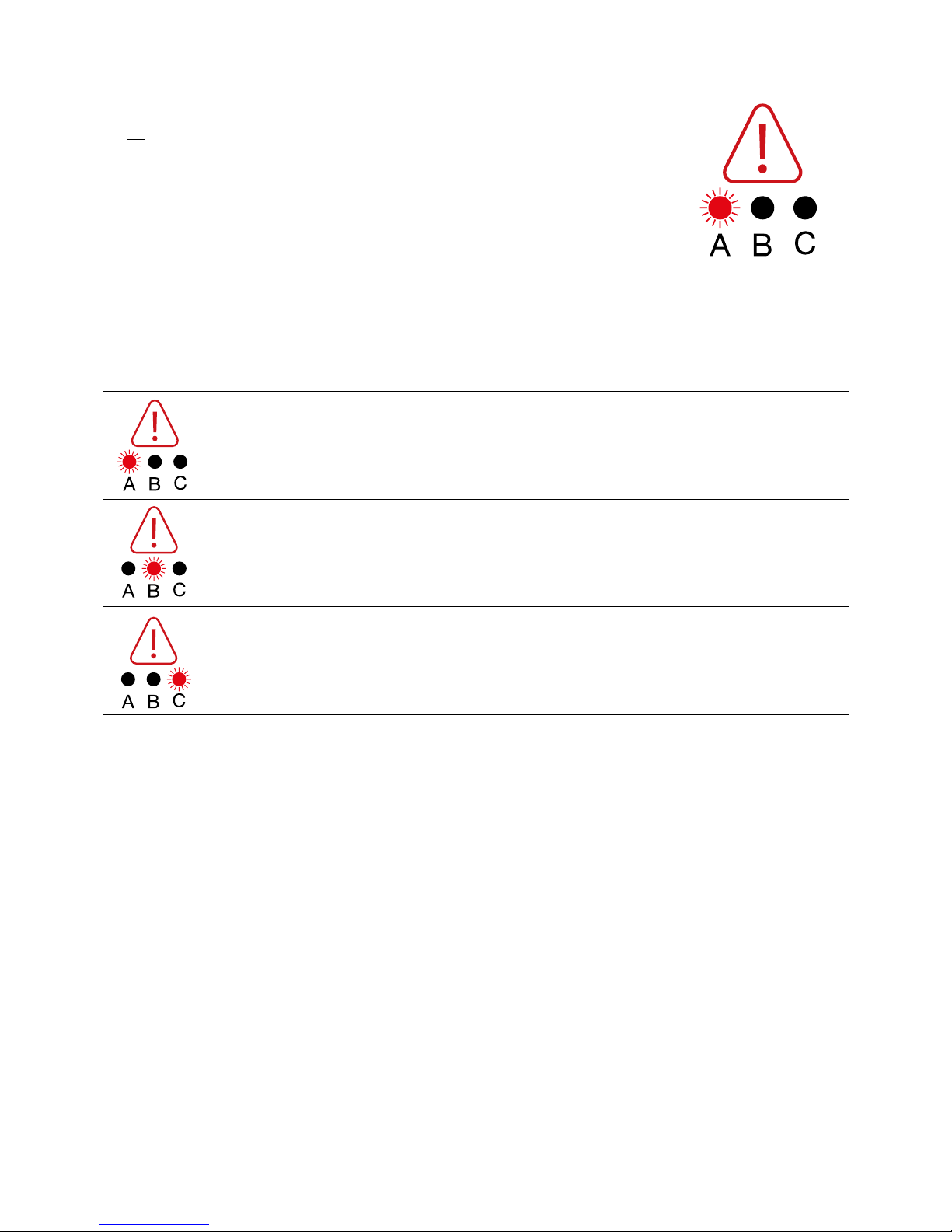
Warning Function
The red Warning LED (A,B or C) flashes, and an audible alert sounds, to indicate the control unit or
mattress pressure has failed. The LED will remain illuminated until appropriate pressure is restored.
The audible warning can be silenced by pressing the Audible Warning Mute button.
The system has three different warning signals, identified by illumination sequences.
The signals and corresponding Pressure Setting LED displays are illustrated below.
High pressure
The system cannot reach the set pressure within 8 minutes.
The system pressure is too high.
Low pressure
The system cannot reach the set pressure within 8 minutes.
The system pressure is too low.
Mains Failure Power unit has no power feed.
Display Warning Signal
 Loading...