

Page 1
DIGITAL OEM INTEGRATION
tm
INSTALLATION
GUIDE
CANBUS DOORLOCK AND
IMMOBILIZER INTERFACE*
*RFLOOP may be required
DLPK
Rev: 20091001
Update Alert: Firmware updates are posted to the web on a
regular basis. We recommend you check for firmware and/or
install guide updates prior to installation of this product.
www.xpresskit.com
© 2009 Directed Electronics. All rights reserved.
Page 2

Page 3
DLPK
CANBUS DOORLOCK AND IMMOBILIZER INTERFACE*
*RFLOOP may be required
Rev: 20090626
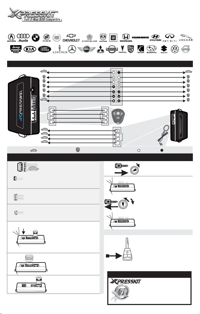
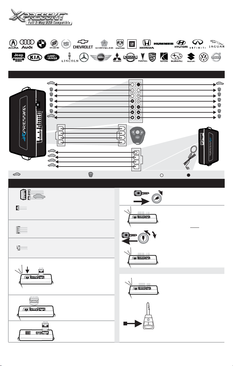
WIRING / CONNECTION GUIDE
Relay NC
Output 3
Tach
button
Programming
Front of the module
START HERE:
1
1.A
Connector 1 (White):
Determine the type of installation:
INSTALLATION WITH OR WITHOUT D2D (See P.6)
1.B
Connector 2 (White):
Make the connections associated with the vehicle in
the VEHICLE FIT GUIDE (P.2-5)
Connector 3 (White, located at the back of the
1.C
module):
Make the connections associated with the vehicle in
the VEHICLE FIT GUIDE (P.2-5)
2
3
2
4
(-) While running (status)
Aux. 1
Lock
Input +12V
Relay Out NO
(CAN High) Data
(CAN Low) Data
(CAN SW) Data
Connect wire to vehicle
Make the connections of the DLPK
to the vehicle:
Press
while inserting the main wires
harness ( ) into the DLPK
module.
1
The LED will illuminate to indicate
you are in programming mode,
release the programming button.
Connect
CONN. 2
()
WARNING: Connector 2 can be
easily plugged in backwards.
Connect
3
CONN. 3
()
Slide door left White/Violet
conn.
D2D Cable
Connect to
Remote starter
conn.
1
INSTALLATION AND PROGRAMMING INSTRUCTIONS
the programming switch
CONN 1
the other connectors
the other connectors
Trunk Output White/Red
2
Connect wire to Remote-Starter/Alarm
Orange
Violet/White
Blue/White
Light Green
Pink
Brown
Orange/Green
Orange/Brown
Light Green
11
44
5
6
*
Chrysler/Dodge/Jeep models
7
The module is now
ready for use.
P. 1
See wiring schematic configuration
81
Yellow
White/Black
~
Grey
~
Green
Violet/Black
Blue
Red/White
14
7
WARNING: Connector 2 can be easily
plugged in backwards.
1
conn.
3
Optional
conn.
Transponder
Bypass Connector
4
()RFLoop Series
OFF
IGN
START
Once the LED starts to flash rapidly
turn the key to the .
GMC
( vehicle : Start the vehicle)
GM
OFF
The LED will turn off to indicate the
IGN
module has been programmed.
START
The module is now ready for use.
(*Chrysler, Dodge, Jeep models
continue with step 7)
The LED will flash until you
the OEM remote lock button
If the vehicle is not equiped with the
OEM remote: press on the
UNLOCK
LOCK
programming button of the module.
PANIC
The LED will turn off to indicate the
module has been programmed.
Relay COM
Future Use
Output 2
Output 1
Aux. 2
Unlock
Trunk
4
Turn the key to the
Back of the module
INPUTOUTPUT
."ON" position
OFF position
press
TECHNICAL SUPPORT / INFORMATION
web resources:
www.xpresskit.com
www.xpressvip.com
www.directechs.com
.
Page 4
DLPK
CANBUS DOORLOCK AND IMMOBILIZER INTERFACE*
*RFLOOP may be required
CÂBLAGE / GUIDE DE CONNECTION
Relay NF
Sortie 3
Tach
(-) Masse d’activation (status)
button
Programming
Front of the module
Branchement du filage au véhicule.
COMMENCEZ ICI:
1
1.A
Connecteur 1 (Blanc):
Déterminez le type d’installation:
INSTALLATION AVEC OU SANS D2D: (P.:6)
1.B
Connecteur 2 (Blanc):
Déterminez le type de branchement selon votre
véhicule (Voir GUIDE DES VOITURES, P.2-5)
Connecteur 3 (Blanc, situé au dos du module):
1.C
Déterminez le type de branchement selon votre
véhicule (Voir GUIDE DES VOITURES, P.2-5)
2
3
2
4
Aux. 1
Verrouillage
Entrée +12V
Relay Out NO
(CAN High) Data
(CAN Low) Data
(CAN SW) Data
conn.
2
Câble D2D
Brancher au
Démarreur à
conn.
1
Distance
Branchement du filage au
démarreur à distance / alarme.
INSTRUCTION D’INSTALLATION ET DE PROGRAMMATION
Effectuez les connexions du DLPK
au véhicule:
Maintenez le bouton de
programmation enfoncé
insérant le dans le
DLPK. La DEL s’allume pour
1
indiquer le début de la
programmation,
bouton de programmation.
3
connecteur 1
relâchez le
Branchez
CONN. 2
()
ATTENTION: Ne pas brancher le
connecteur à l’envers.
Branchez
()
CONN. 3
le connecteur 2.
le connecteur 3.
Orange
Blanc/Rouge
Violet/Blanc
Bleu/Blanc
Blanc/Violet
Vert Pâle
Rose
Orange/Vert
Orange/Brun
Light Green
en
Voir SCHÉMA DE BRANCHEMENT
81
Jaune
Blanc/Noir
~
Gris
~
Vert
Violet/Noir
Bleu
Rouge/Blanc
14
7
ATTENTION: Ne pas brancher le connecteur
11
44
Brun
5
6
*
Chrysler/Dodge/Jeep
7
à l’envers.
1
4
OFF
LOCK
conn.
3
Connecteur pour
contournement
de transpondeur
()RFLoop Series
OFF
IGN
START
Lorsque la DEL clignote
rapidement,
position OFF.
(Sauf véhicules : Démarrez le
véhicule.)
GM
IGN
START
La DEL s’éteint pour indiquer que
le module est programmé.
(*Sauf pour les véhicules
Chrysler, Dodge, Jeep,
poursuivre à l’étape 7.)
La DEL clignotera jusqu’à ce que
vous pressiez le bouton
Verrouillage (Lock) de la
télécommande d’origine du
véhicule.
Si le véhicule n'est pas équipé de
la télécommande d'origine:
appuyez sur le bouton de
programmation du module.
UNLOCK
La DEL s’éteint pour indiquer
PANIC
que le module est programmé.
Relay COM
Future Option
Déverrouillage
Optionel
conn.
4
Tournez la clé en
position ignition.
tournez la clé en
Sortie 2
Sortie 1
Aux. 2
Valise
Vue de dos du module
ENTRÉESORTIE
GMC
P. 2
Page 5
DLPK
CANBUS DOORLOCK AND IMMOBILIZER INTERFACE*
*RFLOOP may be required
Yellow: Jaune
Pink: Rose
White:Blanc
Purple: Mauve
Red: Rouge
Tan: Beige
Brake Signal
See www.xpresskit.ccom for installation / Voir www.xpresskit.com pour les schémas d'installationschematic
See www.xpresskit.ccom for installation / Voir www.xpresskit.com pour les schémas d'installationschematic
See www.xpresskit.ccom for installation / Voir www.xpresskit.com pour les schémas d'installationschematic
CAN High: Orange/Green CAN Low: Green
KIBMW
KIBMW
If push to start see:
Si push to start voir:
Gray: Gris
Lt: Pâle
Orange:
Orange
Black: Noir
Blue: Bleu
Brown: Brun
Green: Vert
Use the PKUCG2X or RFLCHGM
Utiliser le PKUCG2X ou RFLCHGM
VEHICLE FIT GUIDE / GUIDE DES VEHICULES
Additionnal
Parts
Required
RFLUB
A5 - S5
RFLUB
: IK = Intelli-Key
:( ).Window roll down Ouverture des fenêtres
:()Wiring schematic configuration Schema de branchement
: See KIBMW Installation schematic. (Voir Schema d'installation du KIBMW)
-
Q5
S6
RFLUB
Not
RFLCHGM
Not Required
Required
Not
Required
Traverse
RFLCHGM
*
**
***
: Installation schematic coming soon. (Schema d'installation à venir)
****
*****
P. 3
Page 6
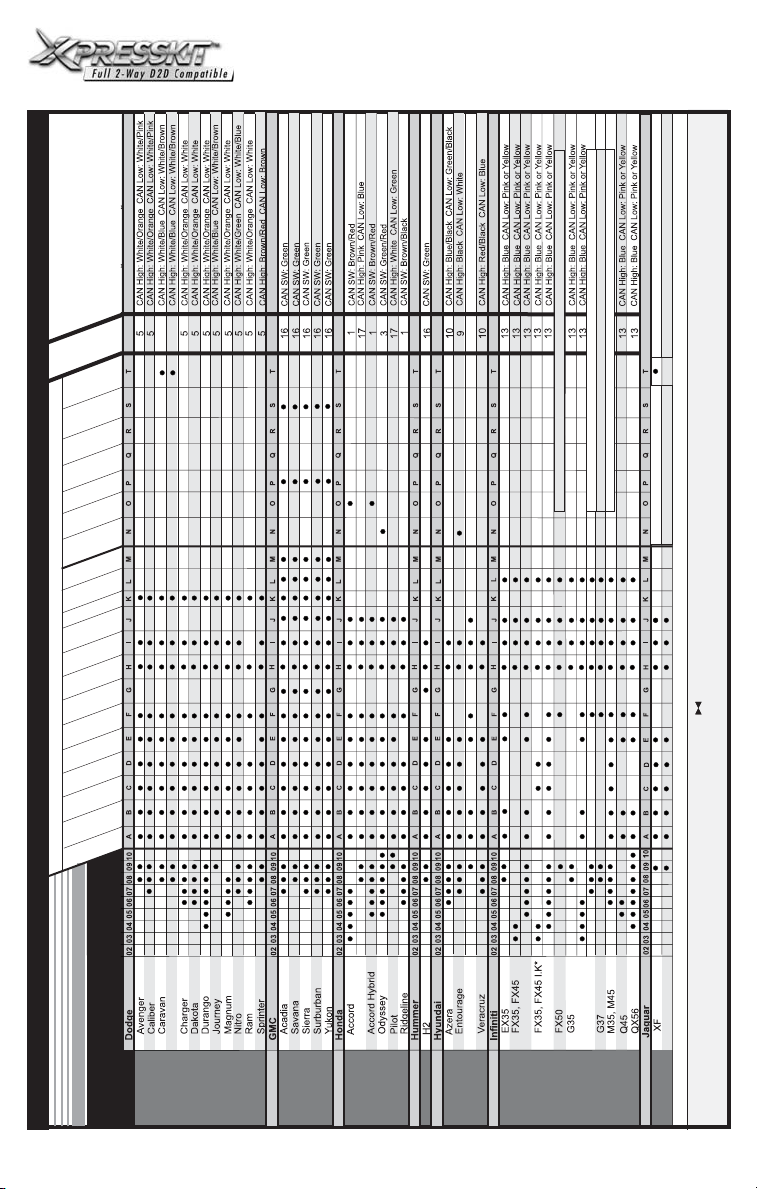
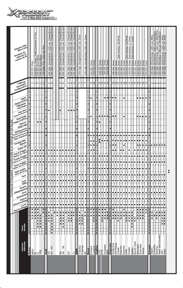
Vehicles Data
Wire Color
Données du
véhicule et
couleur de fil
DLPK
CANBUS DOORLOCK AND IMMOBILIZER INTERFACE*
*RFLOOP may be required
Yellow: Jaune
Pink: Rose
White:Blanc
Purple: Mauve
Red: Rouge
Tan: Beige
23
***Wiring
Schematic
Configuration
Brake Signal
Signale de frein
Hatch
Hayon arrière
**Windows
Roll Down
Gas door
Capuchon Essence
Heat Seats
Sièges chaufants
Defrost
Dégivrage
Sliding doors
Portes coullissantes
PK3,
Passlock
Transponder
Bypass
Radio Off
Hood trigger
Status du capot
Trunk trigger
Status de la valise
Door trigger
Status des portes
Start enable
Active démarrage
Tach
Trunk
Valise
Disarm
Désarmement
Arm
Fonctionnal if equipped | Fonctionnelle si le véhicule en est équipé.
Armement
Unlock
Déverrouillage
Lock
Verrouillage
23
CAN High: Brown CAN Low: White
22
See www.xpresskit.com for installation / Voir www. pour les schémas d'installationschematic xpresskit.com
See www.xpresskit.com for installation / Voir www. pour les schémas d'installationschematic xpresskit.com
xpresskit.com
Voir www. pour les schéma d'installation
See www.xpresskit.com for installation / Voir www. pour les schémas d'installationschematic xpresskit.com
See www.xpresskit.com for installation / Voir www. pour les schémas d'installationschematic xpresskit.com
DLPK Firmware version 12.17 & +
xpresskit.com
Gray: Gris
Lt: Pâle
Orange:
Orange
Voir www. pour les schéma d'installation
Black: Noir
Blue: Bleu
Brown: Brun
Green: Vert
DLPK Firmware version 14.00 & +
Use the PKUCG2X or RFLCHGM
Utiliser le PKUCG2X ou RFLCHGM
Years
Années
Vehicles
VEHICLE FIT GUIDE / GUIDE DES VOITURES
VEHICLE FIT GUIDE / GUIDE DES VEHICULES
Véhicules
Parts
Required
Additionnal
Challenger
RFLCHGM
Not
Required
RFLUB
RFLUB
Genesis
RFLKIA2
Not
Required
: IK = Intelli-Key
:( ).Window roll down Ouverture des fenêtres
:()Wiring schematic configuration Schema de branchement
: See KIBMW Installation schematic. (Voir Schema d'installation du KIBMW)
XK
*
**
***
Not Required
P. 4
: Installation schematic coming soon. (Schema d'installation à venir)
****
*****
Page 7

DLPK
CANBUS DOORLOCK AND IMMOBILIZER INTERFACE*
CAN High: White/Green CAN Low: White/Blue
23
23
schematic
*RFLOOP may be required
schematic
schematic
schematic
schematic
xpresskit.com xpresskit.com
Raider
See www. for installation / Voir www. pour les schéma d'installation
Cube
If remote starter see KILRV
If push to start see KIBMW
xpresskit.com xpresskit.com
See www. for installation / Voir www. pour les schéma d'installation
xpresskit.com xpresskit.com
See www. for installation / Voir www. pour les schéma d'installation
xpresskit.com xpresskit.com
See www. for installation / Voir www. pour les schéma d'installation
xpresskit.com xpresskit.com
See www. for installation / Voir www. pour les schéma d'installation
370Z
VEHICLE FIT GUIDE / GUIDE DES VOITURES
Parts
Required
Additionnal
RFLCHGM
RFLUB
RFLKIA2
RFLUB
RFLUB
RFLUB
RFLMIT3
Not
Required
P. 5
Page 8

DLPK
CANBUS DOORLOCK AND IMMOBILIZER INTERFACE*
CAN High: Blue CAN Low: Pink or Yellow
13
*RFLOOP may be required
CAN High: White/Blue CAN Low White/Brown
CAN High: White/Blue CAN Low: White/Brown
23
23
CAN High: White CAN Low: Green
CAN High: White CAN Low: Green
CAN High: Gray/Orange CAN Low: Purple/Orange
CAN High: Gray/Orange CAN Low: Purple/Orange
CAN High: Gray/Orange CAN Low: Purple/Orange
CAN High: White CAN Low: Green
7
7
8
For remote car starter see: KILRV
For remote car starter see: KILRV
For remote car starter see: KILRV
CAN High: Gray/Orange CAN Low: Purple/Orange
CAN High: White CAN Low: Green
7
For remote car starter see: KILRV
CAN High: White CAN Low: Green
7
Fonctionnal if equipped
G5 - Pursuit
VEHICLE FIT GUIDE / GUIDE DES VÉHICULES
Fonctionnelle si le véhicule en est équipé.
Not
Parts
Required
Additionnal
Required
RFLCHGM
Not Required
RFLUB
RFLUB
Not
Required
RFLUB
Equator
RFLUB
Not Required
GTI
RFLUB
Routan
Routan
S80
RFLUB
V50
V70
Use the PKUCG2X or RFLCHGM | Utiliser le PKUCG2X ou RFLCHGM
XC60
XC70
XC90
P. 6
Page 9

DLPK
CANBUS DOORLOCK AND IMMOBILIZER INTERFACE*
*RFLOOP may be required
INSTALLATION WITH D2D
/ INSTALLATION AVEC D2D
Starter or alarm
Démarreur ou alarme
button
Programming
2
1
Port
D2D
INSTALLATION WITHOUT D2D /
INSTALLATION SANS D2D
Cut off one plug of the D2D
connector, connect the blue wire to
+12V and the black wire to ground.
Coupez les 4 fils à l’extrémité de l’un
des deux connecteurs D2D.
Connectez le fil bleu au 12V et le fil
noir à la masse du véhicule.
button
Programming
Starter or alarm
Démarreur ou alarme
2
1
without
sans
D2D
D2D
Black
Blue +12V
WIRING SCHEMATIC CONFIGURATION / SCHÉMA DE BRANCHEMENT
Configuration 1
N.C.
Trunk Trigger
Tach
(-) While running (status)
Defrost
Lock
Ignition
21 20 19 18 17 16 15 14 13 12 11 10
9 8 7 6 5 3 2 14
Fuse Panel
Panneau à fusibles
Wires located in driver kick panel, PIN-4, bottom row of 21-pin
GREEN plug. (See colors wires on the VEHICLE FIT GUIDE
p.2-5)
Fils situés dans le panneau latéral du côté chauffeur, PIN-4,
dernier rang du connecteur vert de 21 PINS. (Voir la couleur
des fils dans le GUIDE DES VEHICULES p.2-5)
Orange
White/Red
Violet/White
Blue/White
White/Violet
Light Green
Pink
81
Yellow
White/Black
~
Grey
~
Green
Violet/Black
Blue
Red/white
14
7
N.C.
N.C.
N.C.
(CAN SW) Data
N.C.
N.C.
Hood Trigger
Door Trigger
N.C.
Unlock
Brown
Orange/Green
Orange/Brown
Lt. Green
Trunk
Configuration 2
1
4
N.C.
Trunk Trigger
Tach
(-) While running (status)
N.C.
Lock
Ignition
Twisted Pair Wires in driver kick panel or at steering column
(See wires colors VEHICLE FIT GUIDE P.2-5)
Paire de fils torsadés situés dans le panneau latéral du côté
chauffeur ou à la colonne de direction (Voir le GUIDE DES
VÉHICULES, pour la couleur des fils. P.2-5).
Orange
White/Red
Violet/White
Blue/white
White/Violet
Light Green
Pink
(CAN High) Data
(CAN Low) Data
81
Yellow
White/Black
~
Grey
~
Green
Violet/Black
Blue
Red/White
14
7
N.C.
N.C.
Orange/Green
Orange/Brown
N.C.
N.C.
Hood Trigger
Door Trigger
N.C.
Unlock
N.C.
Brown
Lt. Green
1
4
Connect: Branchez:
81
Orange
White/Red
Violet/White
Blue/White
White/violet
Lt. Green
Pink
Connect: Branchez:
Orange
White/Red
Violet/White
Blue/White
White/Violet
Lt. Green
14
Pink
Yellow
White/Black
Grey
Green
Violet/Black
Blue
Red/White
7
81
Yellow
White/Black
Grey
Green
Violet/Black
Blue
Red/White
14
7
D2D (1 way)
Brown
Orange/Green
Orange/Brown
Light Green
D2D (2 way)
Brown
Orange/Green
Orange/Brown
Light Green
Connect: Branchez:
81
Orange
White/Red
1
4
violet/White
Blue/White
White/Violet
Lt. Green
Pink
Connect: Branchez:
Orange
White/red
1
4
Violet/White
Blue/White
White/Violet
Lt. Green
Pink
14
7
81
Yellow
White/Black
Grey
Green
Violet/Black
Blue
Red/White
14
7
Yellow
White/Black
Grey
Green
Violet/Black
Blue
Red/White
D2D (1 way)
Brown
Orange/Green
Orange/Brown
Light Green
D2D (2 way)
Brown
Orange/Green
Orange/Brown
Light Green
1
4
1
4
P. 7
Page 10

DLPK
CANBUS DOORLOCK AND IMMOBILIZER INTERFACE*
WIRING SCHEMATIC CONFIGURATION / SCHÉMA DE BRANCHEMENT
Configuration 3
N.C. N.C.
Trunk Trigger
Tach
(-) While running (status)
Slide Door Left
Lock
White/Red
Violet/white
Blue/White
White/Violet
Light Green
Ignition
21 20 19 18 17 16 15 14 13 12 11 10
9 8 7 6 5 3 2 14
Fuse Panel
Panneau à fusibles
Wires located in driver kick panel, PIN-4, bottom row of 21-pin GREEN plug. (See colors wires on the VEHICLE FIT
GUIDE p.2-5)
Fils situés dans le panneau latéral du côté chauffeur, PIN-4, dernier rang de la connecteur vert de 21 PINS.(Voir la
couleur des fils dans le GUIDE DES VÉHICULES p.2-5)
Connect: Branchez:
81
Orange
White/Red
Violet/White
Blue/White
White/Violet
Lt. Green
Pink
14
Yellow
White/Black
Grey
Green
Violet/Black
Blue
Red/White
7
D2D (1 way)
Brown
Orange/Green
Orange/Brown
Light Green
Configuration 4
N.C. N.C.
Trunk Trigger
Tach
(-) While running (status)
Gas Door
Lock
Orange
White/Red
Violet/White
Blue/White
White/Violet
Light Green
Ignition
Twisted Pair Wires in driver kick panel or at steering column (See wires colors VEHICLE FIT GUIDE P.2-5)
Paire de fils torsadés situés dans le panneau latéral du côté chauffeur ou à la colonne de direction (Voir le GUIDE
DES VÉHICULES, pour la couleur des fils. P.2-5).
8 1
Orange
~
Pink
14
(CAN SW) Data
1
Violet/White
White/Violet
4
4
1
8
~
~
Pink
14
7
(CAN High) Data
(CAN Low) Data
Yellow
White/Black
~
Grey
Green
Violet/Black
Blue
Red/White
7
7
N.C.
N.C.
Orange/Green
N.C.
Orange/Brown
Connect: Branchez:
8 1
Orange
White/Red
Blue/White
Lt. Green
Pink
14
Yellow
White/Black
Grey
Green
Violet/Black
Blue
Red/White
N.C.
N.C.
Orange/Green
Orange/Brown
*RFLOOP may be required
N.C.
Hood Trigger
Door Trigger
Slide Door Right
Unlock
Trunk
N.C.
1
4
Orange/Green
Orange/Brown
Light Green
Brown
Lt. Green
Yellow
White/Black
Grey
Green
Violet/Black
Blue
Red/White
7
Hood Trigger
Door Trigger
N.C.
Unlock
Trunk
Brown
Lt. Green
D2D (2 way)
Brown
1
4
1
4
Connect: Branchez:
8
Orange
White/Red
Violet/White
Blue/White
White/Violet
Lt. Green
Pink
14
1
Yellow
White/Black
Grey
Green
Violet/Black
Blue
Red/White
7
D2D (1 way)
Brown
Orange/Green
Orange/Brown
Light Green
Connect: Branchez:
1
8
Orange
White/Red
1
4
Violet/White
Blue/White
White/Violet
Lt. Green
Pink
14
Yellow
White/Black
Grey
Green
violet/Black
Blue
Red/White
7
D2D (2 way)
Brown
Orange/Green
Orange/Brown
Light Green
1
4
P. 8
Page 11

DLPK
CANBUS DOORLOCK AND IMMOBILIZER INTERFACE*
WIRING SCHEMATIC CONFIGURATION / SCHÉMA DE BRANCHEMENT
Configuration 5
N.C.
Trunk Trigger
Tach
(-) While running (status)
N.C.
Lock
Orange
White/Red
Violet/White
Blue/White
White/Violet
Light Green
Ignition
OR
1
2 3 4 5 6 7 8
Twisted Pair Wires located at transponder connector
CAN HIGH PIN 6, CAN LOW PIN 7
(See colors wires on the VEHICLE FIT GUIDE p.2-5)
Paire de fils torsadés situés au connecteur du transpondeur.
CAN HIGH PIN 6, CAN LOW PIN 7
(Voir la couleur des fils dans le GUIDE DES VÉHICULES p.2-5)
Connect: Branchez:
81
Orange
White/Red
Violet/White
Blue/white
White/Violet
Lt. Green
Pink
14
Yellow
White/Black
Grey
Green
Violet/Black
Blue
Red/White
7
123456
D2D (1 way)
Brown
Orange/Green
Orange/Brown
Light Green
(CAN High) Data
(CAN Low) Data
OR
1
4
Pink
CAN HIGHPIN 5,CAN LOWPIN 6
(See colorswires onVEHICLE FITGUIDE p.2-5)
Paire defils torsadéssitués aucontecteur d’ignition.
CAN HIGHPIN 5,CAN LOWPIN 6
Yellow
White/Black
~
Grey
~
Green
Violet/Black
Blue
Red/White
14
7
N.C.
N.C.
Orange/Green
Orange/Brown
TwistedPair Wireslocated atthe ignitionconnector
(Voircouleur desfils dansle GUIDEDES VÉHICULESp.2-5)
Connect: Branchez:
8
Orange
White/Red
Violet/White
Blue/white
White/Violet
Lt. Green
Pink
14
*RFLOOP may be required
N.C.
N.C.
N.C.
Door Trigger
N.C.
Unlock
Trunk
Brown
Light Green
1
Yellow
White/Black
Grey
Green
Violet/Black
Blue
Red/White
7
Orange/Green
Orange/Brown
1
4
D2D (2 way)
Brown
Light Green
1
4
Configuration 6
N.C.
Trunk Trigger
Tach
(-) While running (status)
N.C.
Lock
Ignition
TOUAREG & CAYENNE:
Always connect the Pink
ignition wire to the vehicle.
Toujours brancher le fil
Rose ignition au véhicule.
Twisted Pair Wires in driver kick panel (See wires colors VEHICLE FIT GUIDE P.2-5)
Paire de fils torsadés situés dans le panneau latéral du côté chauffeur. (Voir le GUIDE DES VÉHICULES, pour la
couleur des fils. P.2-5)
Connect: Branchez:
81
Orange
White/Red
Violet/White
Blue/white
White/Violet
Lt. Green
Pink
14
Yellow
White/Black
Grey
Green
Violet/Black
Blue
Red/White
7
White/Red
Violet/White
White/Violet
Light Green
D2D (1 way)
Brown
Orange/Green
Orange/Brown
Light Green
Orange
Blue/white
Pink
1
4
1
8
Yellow
White/Black
~
Grey
~
Green
Violet/Black
Blue
Red/White
14
7
N.C.
(CAN High) Data
(CAN Low) Data
N.C.
Connect: Branchez:
81
Orange
White/Red
Violet/White
Blue/white
White/Violet
Lt. Green
Pink
14
N.C.
N.C.
Hood Trigger
Door Trigger
N.C.
Orange/Green
Orange/Brown
Light Green
Yellow
White/Black
Grey
Green
Violet/Black
Blue
Red/White
7
Unlock
Trunk
Brown
1
4
D2D (2 way)
Brown
Orange/Green
Orange/Brown
Light Green
1
4
P. 9
Page 12

CANBUS DOORLOCK AND IMMOBILIZER INTERFACE*
*RFLOOP may be required
WIRING SCHEMATIC CONFIGURATION / SCHÉMA DE BRANCHEMENT
Configuration 7
N.C.
Trunk Trigger
Tach
(-) While running (status)
N.C.
Lock
Key Sense
3
2005 +
11
2004 - : Twisted Pair Wires located in the driver kick panel
(See colors wires on the VEHICLE FIT GUIDE p.2-5)
Paire de fils torsadés situés dans le panneau latéral du
côté chauffeur. (Voir la couleur des fils dans le GUIDE
DES VEHICULES p.2-5)
Connect: Branchez:
8
Orange
White/Red
Violet/White
Blue/white
White/Violet
Lt. Green
Pink
14
Connect: Branchez:
81
Orange
White/Red
Violet/White
Blue/white
White/Violet
Lt. Green
Pink
14
Configuration 9
N.C.
Trunk Trigger
N.C.
(-)While running (status)
Sliding Door Left
Lock
Ignition
Twisted Pair Wires coming from the door, located in the
driver kick panel. (See colors wires on the VEHICLE FIT
GUIDE p.2-5)
Paire de fils torsadés provenant de la porte, située dans
le panneau latéral de la porte du côté chauffeur. (Voir la
couleur des fils dans le GUIDE DES VEHICULES p.2-5)
Connect: Branchez:
8
Orange
White/Red
Violet/White
Blue/white
White/Violet
Lt. Green
Pink
14
Connect: Branchez:
8
Orange
White/Red
Violet/White
Blue/white
White/Violet
Lt. Green
Pink
14
Orange
White/Red
Violet/White
Blue/White
White/Violet
Light Green
Pink
(CAN High) Data
(CAN Low) Data
1
Yellow
White/Black
Grey
Green
Violet/Black
Blue
Red/White
7
Yellow
White/Black
Grey
Green
Violet/Black
Blue
Red/White
7
Orange
White/Red
Violet/White
Blue/White
White/Violet
Light Green
Pink
(CAN High) Data
(CAN Low) Data
1
Yellow
White/Black
Grey
Green
Violet/Black
Blue
Red/White
7
1
Yellow
White/Black
Grey
Green
Violet/Black
Blue
Red/White
7
81
~
~
14
7
N.C.
N.C.
Orange/Green
Orange/Brown
Light Green
Orange/Green
Light Green
81
Yellow
White/Black
~
Grey
~
Green
Violet/Black
Blue
Red/White
14
7
N.C.
N.C.
Orange/Green
Orange/Brown
Orange/Green
Orange/Brown
Light Green
Yellow
White/Black
Grey
Green
Violet/Black
Blue
Red/White
Orange/Brown
Light Green
Orange/Green
Orange/Brown
D2D (1 way)
Brown
D2D (2 way)
Brown
Orange/Green
Orange/Brown
D2D (1 way)
Brown
D2D (2 way)
Brown
N.C.
N.C.
N.C.
Door Trigger
N.C.
Unlock
Trunk
Brown
Light Green
1
4
1
4
N.C.
N.C.
N.C.
Door Trigger
Sliding Door Right
Unlock
Brown
Light Green
1
4
1
4
Trunk
Configuration 8
N.C.
Trunk Trigger
Tach
(-)While running (status)
N.C.
Lock
Key Sense
1
4
1
4
3
2005 +
11
2004 - : Twisted Pair Wires located in the driver kick
panel (See colors wires on the VEHICLE FIT GUIDE
p.2-5)
Paire de fils torsadés situés dans le panneau latéral du
côté chauffeur. (Voir la couleur des fils dans le GUIDE
DES VEHICULES p.2-5)
Connect: Branchez:
Orange
White/Red
Violet/White
Blue/white
White/Violet
Lt. Green
Pink
Connect: Branchez:
Orange
White/Red
Violet/White
Blue/white
White/Violet
Lt. Green
Pink
Configuration 10
N.C.
Trunk Trigger
N.C.
(-)While running (status)
N.C.
Lock
Ignition
Twisted Pair Wires coming from the door, located in the
driver kick panel (See colors wires on the VEHICLE FIT
GUIDE p.2-5)
Paire de fils torsadés provenant de la porte, située dans le
panneau latéral côté conducteur.(Voir la couleur des fils
dans le GUIDE DES VEHICULES p.2-5)
Connect: Branchez:
81
Orange
White/Red
Violet/White
Blue/white
White/Violet
Lt. Green
Pink
14
Connect: Branchez:
81
Orange
White/Red
Violet/White
Blue/white
White/Violet
Lt. Green
Pink
14
Orange
White/Red
Violet/White
Blue/White
White/Violet
Light Green
Pink
1
8
Yellow
White/Black
Grey
Green
Violet/Black
Blue
Red/White
14
7
1
8
Yellow
White/Black
Grey
Green
Violet/Black
Blue
Red/White
14
7
Orange
White/Red
Violet/White
Blue/White
White/Violet
Light Green
Pink
(CAN High) Data
(CAN Low) Data
Yellow
White/Black
Grey
Green
Violet/Black
Blue
Red/White
7
Yellow
White/Black
Grey
Green
Violet/Black
Blue
Red/White
7
8
1
~
~
Red/White
14
7
N.C.
(CAN High) Data
(CAN Low) Data
N.C.
81
Yellow
White/Black
~
Grey
~
Green
Violet/Black
Blue
Red/White
14
7
N.C.
N.C.
Orange/Green
Orange/Brown
Orange/Green
Orange/Brown
Yellow
White/Black
Grey
Green
Violet/Black
Blue
D2D (1 way)
Orange/Green
Orange/Brown
Light Green
D2D (2 way)
Orange/Green
Orange/Brown
Light Green
Orange/Green
Orange/Brown
D2D (1 way)
Brown
Light Green
D2D (2 way)
Brown
Light Green
DLPK
N.C.
N.C.
Hood Trigger
Door Trigger
N.C.
Unlock
Trunk
Brown
Orange/Green
Orange/Brown
Light Green
1
Brown
4
1
Brown
4
N.C.
N.C.
N.C.
Door Trigger
N.C.
Unlock
Trunk
Brown
Light Green
1
4
1
4
P.10
1
1
4
1
4
Page 13

CANBUS DOORLOCK AND IMMOBILIZER INTERFACE*
*RFLOOP may be required
WIRING SCHEMATIC CONFIGURATION / SCHÉMA DE BRANCHEMENT
Configuration 11
N.C.
Trunk Trigger
Tach
(-)While running (status)
N.C.
Lock
Ignition
Twisted Pair Wires located under
the glove compartment at the
BCM. (See colors wires on the
VEHICLE FIT GUIDE p.2-5)
Paire de fils torsadés situés sous
le coffre à gant au BCM. (Voir la
couleur des fils dans le GUIDE
DES VÉHICULES p.2-5)
Violet/White
White/Violet
Violet/White
White/Violet
Configuration 13
White/Red
Violet/White
White/Violet
Light Green
Connect: Branchez:
81
Orange
White/Red
Blue/white
Lt. Green
Pink
14
Connect: Branchez:
81
Orange
White/Red
1
Blue/white
Lt. Green
Pink
4
14
To control de OEMAlarm on vehicle vehicles)
following wires to the empty pins on the BCM.
Pour contrôler l'alarme d'origine des véhicules
ajoutez des fils dans les espaces vides du BCM.
Vehicle security light
Lumière de sécurité du véhicule
LED
Driver door pin
Tach
(-)While running (status)
N.C.
Lock
Ignition
1
Brown
Orange/Green
Orange/Brown
Light Green
Orange
White/Red
Violet/White
Blue/White
White/Violet
Light Green
(CAN High) Data
(CAN Low) Data
Orange
Blue/White
Pink
Yellow
White/Black
Grey
Green
Violet/Black
Blue
Red/White
7
Yellow
White/Black
Grey
Green
Violet/Black
Blue
Red/White
7
Pink
N.C.
N.C.
81
~
~
14
7
(CAN High) Data
(CAN Low) Data
Orange/Green
Orange/Brown
Orange/Green
Orange/Brown
81
Yellow
White/Black
~
Grey
~
Green
Violet/Black
Blue
Red/White
14
7
Yellow
White/Black
Grey
Green
Violet/Black
Blue
Red/White
N.C.
N.C.
D2D (1 way)
Brown
Light Green
D2D (2 way)
Brown
Light Green
Door+Trunk Trigger
N.C.
N.C.
N.C.
Door Trigger
N.C.
Unlock
Trunk
Brown
Orange/Green
Orange/Brown
Light Green
1
4
(NON INTELLI-KEY
N.C.
Hood Trigger*
N.C.
Configuration 12
N.C.
N.C.
Tach
(-)While running (status)
N.C.
Lock
Ignition
1
4
6
14
White/Red
Violet/White
Blue/white
White/Violet
Lt. Green
White/Red
Violet/White
1
Blue/white
White/Violet
Lt. Green
4
add the
NON ÉQUIPÉS DE L'INTELLI-KEY
* Only if the vehicle
is equipped with
a hood pin.
* Seulement si le
Unlock
Trunk
véhicule est
équipé de la
pin de capot.
81
Orange
White/Red
Violet/White
Blue/White
White/Violet
Light Green
(CAN High) Data
(CAN Low) Data
Connect: Branchez:
81
Orange
Pink
14
Connect: Branchez:
81
Orange
Pink
14
UNLOCK
LOCK
20 1817 15 14 13 121619
40 39 3837 36 35 34 33 32 31 30 29 28 27 26 25 24 23 22
Yellow
White/Black
~
Grey
~
Green
Violet/Black
Blue
Red/White
Pink
14
7
N.C.
N.C.
4
4
Yellow
White/Black
Grey
Green
Orange/Green
Violet/Black
Orange/Brown
Blue
Red/White
7
Yellow
White/Black
Grey
Green
Violet/Black
Blue
Red/White
7
Light Green
D2D (2 way)
Orange/Green
Orange/Brown
Light Green
Front view of the BCM connector
located on the driver kick panel or
above the accelerationpedal. For the
Versa vehicle: Connector located
behind theglove compartiment.
Vue de face de laprise du BCM situé
dans le panneau latéral côté
conducteur ou au-dessus de la
pédale d'accélération. Pour les
véhicules Versa: Connecteur situé
derrière lecoffre àgant.
11 109876543 21
DLPK
N.C.
N.C.
N.C.
Door + Trunk Trigger
N.C.
Unlock
Trunk
Brown
Orange/Green
Orange/Brown
Light Green
D2D (1 way)
Brown
1
Brown
4
1
4
21
Connect: Branchez:
Orange
White/Red
Violet/White
Blue/white
White/Violet
Lt. Green
Pink
14
81
Yellow
White/Black
Grey
Green
Violet/Black
Blue
7
Red/White
7
1
Brown
Orange/Green
Orange/Brown
Light Green
D2D (2 way)
Brown
Orange/Green
Orange/Brown
Light Green
OR / OU
N.C.
(CAN High) Data
(CAN Low) Data
N.C.
1
4
Connect: Branchez:
8 1
Orange
White/Red
Violet/White
Blue/white
White/Violet
Lt. Green
Pink
14
7
6
14
Yellow
White/Black
Grey
Green
Violet/Black
Blue
Red/White
7
D2D (1 way)
Brown
Orange/Green
Orange/Brown
Light Green
1
4
P.11
Page 14

CANBUS DOORLOCK AND IMMOBILIZER INTERFACE*
*RFLOOP may be required
WIRING SCHEMATIC CONFIGURATION / SCHÉMA DE BRANCHEMENT
Configuration 14
Green/Purple - Vert/Mauve
Driver door pin
Pin porte chauffeur
Trunk Trigger
Tach
(-)While running (status)
Lock
Ignition
White/Red
Violet/White
White/Violet
Light Green
Orange
Blue/White
Pink
3
Connect: Branchez:
81
Orange
Pink
14
11
Yellow
White/Black
Grey
Green
Violet/Black
Blue
Red/White
7
D2D (1 way)
Brown
Orange/Green
Orange/Brown
Light Green
At SJB Connector pin 11
Located in driver kick panel
1
8
Yellow
White/Black
~
Grey
~
Green
Violet/Black
Blue
Red/White
14
7
N.C.
N.C.
Door Trigger
N.C.N.C.
Unlock
Trunk
White/Red
Violet/White
Blue/white
White/Violet
Lt. Green
N.C.
(CAN High) Data
(CAN Low) Data
N.C.
Connect: Branchez:
81
Orange
White/Red
Violet/White
1
Blue/white
White/Violet
Lt. Green
Pink
4
14
7
DLPK
Brown
Orange/Green
Orange/Brown
Light Green
4
D2D (2 way)
Yellow
White/Black
Grey
Green
Violet/Black
Orange/Green
Blue
Orange/Brown
Red/White
Light Green
Brown
1
1
4
Configuration 15
Remote-Starter / Démarreur à distance
WARNING:
of the remote starter must be connected at
the ignition barrel.
ATTENTION:
d'accessoire du démarreur à distance doivent
être connectés au barillet d'ignition.
All Ignition and accessory wires
Les fils d'ignition et
Ignition connector
Connecteur d'ignition
Transponder connector
Connecteur du transpondeur
IGNITION
8
~
Pink
14
N.C.
N.C.
D2D (1 way)
Brown
Orange/Green
Orange/Brown
Light Green
D2D (2 way)
Brown
Orange/Green
Orange/Brown
Light Green
White/Black
White/Black
White/Black
White/Black
White/Black
White/Black
White/Black
White
White/Black
1
~
7
Yellow
White/Black
Grey
Green
Violet/Black
Blue
Red/White
R Code
N.C.
Data (Keyless)
Door Trigger
Sliding Door Right
Unlock
Trunk
1
1
Tan white or light Green.
Beige blanc ou Vert pâle
4
1
Connection needed for vehicles 2006 and older. ( for vehicles 2007 and
newer.) Effectuez ce branchement pour les véhicules 2006 et moins. (sur véhicules
2007 et plus branchement )
4
V DATA
White Brown Yellow
White
White
White
White
White
White
White/Black
White
18
C2
72
Wire colors / Couleur(s) des fils
ACCESSORY
Brown
Brown
Brown
Brown
Brown
Brown
Brown
Brown
ACCESSORY
V DATA
(-) While
running
(status)
V REFERENCE
Connection for Transponder bypass./
Connexion pour le contournement transpondeur.
For OEM door lock control and trunk release
Pour contrôle du verrouillage des portes et valise.
Pin 12
1
55
C2
BCM
C1
Not requiered
non requis
IGNITION
Yellow
Pink
Yellow
Pink
Yellow
Yellow
Pink
Yellow
CAN SW
Green Tan/White
Green
Green
Green
Green
Green
Green
Green
Green
86
87
87a
30
C3
85
Located on the
right side of the
center console.
Situé du côté
droit de la
console centrale.
DATA KEYLESS
Tan/White
Lt Green
Tan/White
Lt Green
Tan/White
Tan/White
Lt Green
Tan/White
R. Code
Trunk Trigger
Tach
(-)While running (status)
Sliding Door Left
Lock
Accessory
1
Brown
Orange/Green
Orange/Brown
Light Green
4
Connect: Branchez:
81
Orange
White/Red
Violet/White
Blue/white
White/Violet
Lt. Green
Pink
14
Connect: Branchez:
81
Orange
White/Red
Violet/White
Blue/white
White/Violet
Lt. Green
Pink
14
Vehicles
Véhicules
Chevrolet
Cobalt
HHR
Malibu
Pontiac
G5
G6
Pursuit
Solstice
Saturn
Aura
Sky
White: Blanc Black: Noir Blue: Bleu Brown: Brun Green: Vert Gray: Gris Lt: Pâle Orange: Orange Pink: Rose Purple: Mauve Red: Rouge Tan: Beige Yellow: Jaune
Yellow
White/Black
Grey
Green
Violet/Black
Blue
Red/White
7
Yellow
White/Black
Grey
Green
Violet/Black
Blue
Red/White
7
Orange
White/Red
Violet/White
Blue/White
White/Violet
Light Green
V REF
(CAN SW) Data
V REFERENCE
Red/White
Rouge/Blanc
P.12
Page 15

DLPK
CANBUS DOORLOCK AND IMMOBILIZER INTERFACE*
WIRING SCHEMATIC CONFIGURATION / SCHÉMA DE BRANCHEMENT
Configuration 15
Configuration 16
Remote-Starter / Démarreur à distance
WARNING:
remote starter must be connected at the ignition barrel.
ATTENTION:
démarreur à distance doivent être connectés au barillet
d'ignition.
All Ignition and accessory wires of the
Les fils d'ignition et d'accessoire du
Connection for Transponder bypass. / Connexion pour le contournement transpondeur.
Ignition connector
Connecteur d'ignition
*RFLOOP may be required
Trunk Trigger
Tach
(-)While running (status)
Gate Open
Lock
Accessory
1
Brown
Orange/Green
Orange/Brown
Light Green
4
Connect: Branchez:
81
Orange
White/Red
Violet/White
Blue/white
White/Violet
Lt. Green
Pink
14
Vehicles
Véhicules
Buick
Enclave
Lucerne
Cadillac
CTS
DTS
Escalade
SRX
STS
Chevrolet
Avalanche
CK Pickup
Equinox
Express
Impala
Monte Carlo
Silverado
Suburban
Tahoe
Traverse
GMC
Acadia
Savana
Sierra
Suburban
Yukon
Hummer
H2
Saturn
Outlook
Vue
Pontiac
G8
Torrent
Suzuki
XL7
8
1
~
~
Pink
14
V REF
N.C.
N.C.
(CAN SW) Data
D2D (1 way)
Brown
Orange/Green
Orange/Brown
Light Green
Yellow
White/Black
Grey
Green
Violet/Black
Blue
Red/White
7
V DATA
Pink/Black
Pink/Black
Pink/Black Yellow
Pink/Black
Pink/Black
Pink/Black
White/Black
Pink/Black
Pink/Black
Pink/Black
R Code
Hood Trigger**
Door/Trunk Trigger
Heat Seats
Trunk/Hatch window
Connect: Branchez:
Orange
White/Red
Violet/White
1
Blue/white
White/Violet
Lt. Green
Pink
4
Wire colors / Couleur(s) des fils
White
White
White
White
White
White Brown
Pink
White
White
White
White
Pink/Black
White/Black
White/Black Yellow Pink
White
White
White
OrangeN.C.
White/Red
Violet/White
Blue/White
White/Violet
Light Green
Yellow
White/Black
Grey
Green
Violet/Black
Blue
Red/White
7
V REFERENCE
White/Black
White/Black
White/Black
White/Black
White
White/Black
White
White
White/Black
White
White/Black
White/Black
White
White
White
White/Black
White/Black
White
White
White
White
White/Black
White
White
White/Black
White/Black
White/Black Brown
Unlock
81
Yellow
White/Black
Grey
Green
Violet/Black
Blue
Red/White
14
7
ACCESSORY
IGNITION
ACCESSORY
Transponder connector
V DATA
V REFERENCE
** Only if the vehicle is equipped with a hood pin.
** Seulement si le véhicule est équipé d’un interrupteur de capot.
D2D (2 way)
1
Brown
Orange/Green
Orange/Brown
Brown
Brown
Brown
Brown
Yellow
Brown
Yellow
Brown
Brown
Brown
Yellow
Yellow
Yellow
Brown
Brown
Yellow
Yellow
Yellow
Yellow
Yellow
Brown
Brown
Brown
Light Green
4
IGNITION
Pink
Pink
Pink
Pink
Pink
Pink
Pink
Pink
Pink
Pink
Pink
Pink
Pink
Pink
Pink
Pink
Pink
Pink
Pink
Pink
Pink
Pink
Pink
Pink
Pink
Pink
Connecteur du transpondeur
WARNING:
disconnected, once reconnected the
vehicle need to be started with the key.
ATTENTION:
est débranché: une fois le module
rebranché, démarrez le véhicule avec
la clé.
CAN SW
Green
Green
Green
Green
Green
Green
Green
Green
Green
Green
Green
Green
Green
Green
Green
Green
Green
Green
Green
Green
Green
Green
Green
Green
Green
Green
Green
Green
Brown
Brun
or
Yellow
Jaune
Every time the DLPK is
Chaque fois que le DLPK
DATA KEYLESS
N.A.
N.A.
N.A.
N.A.
N.A.
N.A.
N.A.
N.A.
N.A.
N.A.
N.A.
N.A.
N.A.
N.A.
N.A.
N.A.
N.A.
N.A.
N.A.
N.A.
N.A.
N.A.
N.A.
N.A.
N.A.
N.A.
N.A.
N.A.
Green
Vert
P.13
Page 16

DLPK
CANBUS DOORLOCK AND IMMOBILIZER INTERFACE*
WIRING SCHEMATIC CONFIGURATION / SCHÉMA DE BRANCHEMENT
Configuration 15
Configuration 17
Orange
White/Red
Violet/White
Blue/White
White/Violet
Light Green
Brown
Orange/Green
Orange/Brown
Light Green
Pink
12 567
34
Blue
Pink
N.C.
Trunk Trigger
Tach
(-)While running (status)
N.C.
Lock
Ignition
Wires located at steering column immobilizer
control unit
Fils situés à la colonne de direction au module
de contrôle de la clé à puce
(CAN High) Data
(CAN Low) Data
N.C.
N.C.
*RFLOOP may be required
81
Yellow
White/Black
14
~
1
4
~
Grey
Green
Violet/Black
Blue
Red/White
7
Hood Trigger
Door Trigger
N.C.
N.C.
N.C.
Unlock
Trunk
Connect: Branchez:
81
Orange
White/Red
Violet/White
Blue/white
White/Violet
Lt. Green
Pink
Configuration 15Configuration 18
Twisted Pair Wires located at
steering column or near cluster
(See colors wires on the
VEHICLE FIT GUIDE p.2-5)
Paire de fils torsadés situés
dans le harnais de la colonne
de direction ou sous le tableau
de bord. (Voir la couleur des fils
dans le GUIDE DES
VÉHICULES p.2-5)
Connect: Branchez:
Orange
White/Red
Violet/White
Blue/white
White/Violet
Lt. Green
Pink
14
81
Yellow
White/Black
Grey
Green
Violet/Black
Blue
Red/White
14
7
Yellow
White/Black
Grey
Green
Violet/Black
Blue
Red/White
7
D2D (1 way)
Brown
Orange/Green
Orange/Brown
Light Green
N.C.
Trunk Trigger
Tach
(-)While running (status)
N.C.
Lock
Ignition
D2D (1 way)
Brown
Orange/Green
Orange/Brown
Light Green
1
4
Violet/White
1
White/Violet
4
Orange
White/Red
Violet/White
Blue/White
White/Violet
Light Green
Pink
White/Red
Violet/White
Blue/white
White/Violet
Lt. Green
Connect: Branchez:
81
Orange
White/Red
Blue/white
Lt. Green
Pink
14
81
Yellow
White/Black
~
Grey
~
Green
Violet/Black
Blue
Red/White
14
7
(CAN High) Data
(CAN Low) Data
Connect: Branchez:
81
Orange
Pink
14
Yellow
White/Black
Grey
Green
Violet/Black
Blue
Red/White
7
Yellow
White/Black
Grey
Green
Violet/Black
Blue
Red/White
7
N.C.
N.C.
Orange/Green
Orange/Brown
Light Green
Door Trigger
N.C.
Orange/Green
Orange/Brown
Light Green
D2D (2 way)
Brown
Orange/Green
Orange/Brown
Light Green
D2D (2 way)
Brown
N.C.
N.C.
N.C.
Unlock
Trunk
Brown
1
4
1
4
1
4
P.14
Page 17

DLPK
CANBUS DOORLOCK AND IMMOBILIZER INTERFACE*
WIRING SCHEMATIC CONFIGURATION / SCHÉMA DE BRANCHEMENT
Configuration 19
Connect: Branchez:
Orange
White/Red
Violet/White
Blue/white
White/Violet
Lt. Green
Pink
Trunk Trigger
Tach output
(-)While running (status)
Lock
Ignition
1
81
Yellow
White/Black
Grey
Green
Violet/Black
Blue
Red/White
14
7
N.C.
D2D (1 way)
Orange/Green
Orange/Brown
Light Green
Orange
White/Red
Violet/White
Blue/White
White/Violet
Light Green
Pink
Brown
81
~
~
14
7
Brown
Orange/Green
1
Orange/Brown
Light Green
4
White/Red
Violet/White
1
White/Violet
4
Yellow
White/Black
Grey
Green
Violet/Black
Blue
Red/White
Connect: Branchez:
81
Orange
Blue/white
Lt. Green
Pink
14
Door Trigger
(CAN High) Data
(CAN Low) Data
1
N.C.
Yellow
White/Black
Grey
Green
Violet/Black
Blue
Red/White
7
Unlock
Trunk
Data
Data
N.C.
N.C.
D2D (2 way)
Brown
Orange/Green
Orange/Brown
Light Green
*RFLOOP may be required
BCM located directly below
the steering column.
BCM situés directement
1
sous la colonne de direction.
BCM
3 or 4 connectors
3 à 4 connecteurs
4
PIN 27
PIN 24
PIN 26
PIN 1
PIN 9
Vehicles
Véhicules
Subaru
Impreza Pink Light Green/Red Yellow/Green
Forester
Legacy
Outback
Tribeca
Configuration 15Configuration 20
N.C.
Trunk Trigger
Tach
(-)While running (status)
N.C.
Lock
Accessory
1
Brown
Orange/Green
Orange/Brown
Light Green
4
CAN HIGH CAN LOW Data BCMPIN PIN PIN
Pink
Pink
Pink
Pink
REMOTE STARTER
DÉMARREUR À DISTANCE
La sortieStart dudémarreur à distancen’est pasrequise pour cevéhicule.
81
Orange
White/Red
Violet/White
Blue/White
White/Violet
Light Green
(CAN High) Data
(CAN Low) Data
CAN SW
Pink
14
~
Yellow
White/Black
~
Grey
Green
Violet/Black
Blue
Red/White
7
Wire Color / Couleur(s) des fils
1
Blue
1
Violet
27
Violet
27
Violet
27
The remotestarters startoutput is notrequired.
Make 10 loops with a 22 to 26 gauge wire
around the factory key.
Faire 10 tours autour de la clé d’origine avec
un fil de calibre 22 à 26.
N.C.
N.C.
Door Trigger
Window roll down
Unlock
N.C.
OBDII pin 6
OBDII pin 14
OBDII pin 1
1 6
14
Connect: Branchez:
Orange
White/Red
Violet/White
Blue/white
White/Violet
Lt. Green
Pink
1
81
14
7
Yellow
White/Black
Grey
Green
Violet/Black
Blue
Red/White
D2D (1 way)
Brown
Orange/Green
Orange/Brown
Light Green
1
4
White/Red
Violet/White
Blue/white
White/Violet
Lt. Green
Connect: Branchez:
1
81
Orange
Pink
14
Yellow
White/Black
Grey
Green
Violet/Black
Blue
Red/White
7
D2D (2 way)
Brown
Orange/Green
Orange/Brown
Light Green
1
4
9
9
26
26
26
Grey/Red
Yellow/Green
Yellow/Green
Yellow/Green
Ignition
Accessory
Brown/Green
Remove the plastic cover of the
1
Ignition barrel
Retirez le couvert de plastique
du barillet d’ignition.
Wrap the wire around the inside
2
of the plastic ring 4 times.
Faire a 4 tours à l ’intérieur de
l’anneau de plastique avec le fil.
24
24
9
9
9
Black
Ignition barrel
Barillet d’ignition.
P.15
Page 18

CANBUS DOORLOCK AND IMMOBILIZER INTERFACE*
*RFLOOP may be required
WIRING SCHEMATIC CONFIGURATION / SCHÉMA DE BRANCHEMENT
Configuration 15Configuration 21
N.C.
Trunk Trigger
Tach
(-)While running (status)
Lock
Ignition
3
11
Configuration 15
Configuration 22
Trunk Trigger
Tach
(-)While running (status)
Lock
Ignition
Twisted Pair Wires in driver kick
panel (See wires colors VEHICLE
FIT GUIDE P.2-3)
Paire de fils torsadés situés dans le
panneau latéral du côté chauffeur.
(Voir le GUIDE DES VÉHICULES,
pour la couleur des fils. P.2-3)
Violet/White
White/Violet
Light Green
N.C.
Violet/White
N.C.
White/Violet
Orange
White/Red
Blue/White
Pink
(CAN High) Data
(CAN Low) Data
Orange
White/Red
Blue/White
Light Green
Pink
1
8
Yellow
White/Black
~
Grey
~
Green
Violet/Black
Blue
Red/White
14
7
N.C.
N.C.
1
8
Yellow
White/Black
Grey
~
Green
Violet/Black
Blue
Red/White
14
7
*Functional only when the vehicle is running.
*Fonctionne seulement lorsque le véhicule
est en fonction.
(CAN High) Data
(CAN Low) Data
N.C.
N.C.
N.C.
N.C.
N.C.
Door Trigger
N.C.N.C.
Orange/Green
Orange/Brown
Light Green
N.C.
N.C.
Hood Trigger
Door Trigger
N.C.
Unlock
Trunk
Brown
Unlock
Trunk*
Brown
Orange/Green
Orange/Brown
Light Green
1
4
1
4
White/Red
Violet/White
Blue/white
White/Violet
White/Red
Violet/White
Blue/white
White/Violet
Violet/White
White/Violet
Violet/White
White/Violet
Connect: Branchez:
1
81
Orange
Lt. Green
Pink
14
Connect: Branchez:
1
81
Orange
Lt. Green
Pink
14
Connect: Branchez:
881
Orange
White/Red
Blue/white
Lt. Green
Pink
14
Connect: Branchez:
881
Orange
White/Red
Blue/white
Lt. Green
Pink
14
Yellow
White/Black
Grey
Green
Violet/Black
Blue
Red/White
7
Yellow
White/Black
Grey
Green
Violet/Black
Blue
Red/White
7
1
Yellow
White/Black
Grey
Green
Violet/Black
Blue
Red/White
7
1
Yellow
White/Black
Grey
Green
Violet/Black
Blue
Red/White
7
DLPK
D2D (2 way)
Brown
Orange/Green
Orange/Brown
Light Green
D2D (1 way)
Brown
Orange/Green
Orange/Brown
Light Green
D2D (2 way)
Brown
Orange/Green
Orange/Brown
Light Green
D2D (1 way)
Brown
Orange/Green
Orange/Brown
Light Green
1
4
1
4
1
4
1
4
Configuration 15
Configuration 23
N.C.
Trunk Trigger
Tach
(-)While running (status)
N.C.
Lock
Ignition
1
2 3 4 5 6 7 8
Orange
White/Red
Violet/White
Blue/White
White/Violet
Light Green
OR
123456
Twisted Pair Wires located at steering column or near
cluster (See colors wires on the VEHICLE FIT GUIDE p.2-5)
Paire de fils torsadés situés dans le harnais de la colonne de
direction ou sous le tableau de bord. (Voir la couleur des fils
dans le GUIDE DES VÉHICULES p.2-5)
1
8
Yellow
White/Black
Grey
~
Green
Violet/Black
Blue
Pink
Red/White
14
7
Must be fused 5Amp brake power
Installez un fusible 5Amp à la source
de courant des freins.
12v
12v
(CAN High) Data
(CAN Low) Data
N.C.
Connect: Branchez:
1
Brake OUT
N.C.
Hood Trigger
Door Trigger
N.C.
Unlock
Trunk
Orange/Green
Orange/Brown
Light Green
Brown
1
4
White/Red
Violet/White
Blue/white
White/Violet
Lt. Green
White/Red
Violet/White
Blue/white
White/Violet
Lt. Green
1
Orange
Orange
Yellow
White/Black
Grey
Green
Violet/Black
Blue
Red/White
Pink
14
7
Connect: Branchez:
1
1
Yellow
White/Black
Grey
Green
Violet/Black
Blue
Red/White
Pink
14
7
OR
Twisted Pair Wires located at the ignition connector (See
colors wires on VEHICLE FIT GUIDE p.2-5) Paire de fils
torsadés situésau contecteur d’ignition. (Voircouleur desfils
dans leGUIDE DESVÉHICULES p.2-5)
D2D (2 way)
Brown
Orange/Green
Orange/Brown
Light Green
D2D (1 way)
Brown
Orange/Green
Orange/Brown
Light Green
1
4
1
4
P.16
Page 19

Page 20

DLPK
CANBUS DOORLOCK AND IMMOBILIZER INTERFACE*
LIMITED ONE-YEAR CONSUMER WARRANTY
For a period of ONE YEAR from the date of purchase of a Directed Electronics remote start or security
product, Directed Electronics. (“DIRECTED”) promises to the original purchaser, to repair or replace
with a comparable reconditioned piece, the security or remote start accessory piece (hereinafter the
“Part”), which proves to be defective in workmanship or material under normal use, provided the
following conditions are met: the Part was purchased from an authorized DIRECTED dealer; and the
Part is returned to DIRECTED, postage prepaid, along with a clear, legible copy of the receipt or bill of
sale bearing the following information: consumer’s name, address, telephone number, the authorized
licensed dealer’s name and complete product and Part description.
This warranty is nontransferable and is automatically void if the Part has been modified or used in a
manner contrary to its intendedpurpose or the Part has been damaged by accident, unreasonable use,
neglect, improper service, installation or other causes not arising out of defect in materials or
construction.
TO THE MAXIMUM EXTENT ALLOWED BY LAW, ALL WARRANTIES, INCLUDING BUT NOT
LIMITED TO EXPRESS WARRANTY, IMPLIED WARRANTY, WARRANTY OF MERCHANTABILITY,
FITNESS FOR PARTICULAR PURPOSE AND WARRANTY OF NON INFRINGEMENT OF
INTELLECTUAL PROPERTY, ARE EXPRESSLYEXCLUDED; ANDDIRECTED NEITHERASSUMES
NOR AUTHORIZES ANY PERSON OR ENTITY TO ASSUME FOR IT ANY DUTY, OBLIGATION OR
LIABILITY IN CONNECTION WITH ITS PRODUCTS. DIRECTED HEREBY DISCLAIMS AND HAS
ABSOLUTELY NO LIABILITY FORANY ANDALL ACTS OF THIRD PARTIES INCLUDING DEALERS
OR INSTALLERS. IN THE EVENT OF A CLAIM OR A DISPUTE INVOLVING DIRECTED OR ITS
SUBSIDIARY, THE PROPER VENUE SHALL BE SAN DIEGO COUNTY IN THE STATE OF
CALIFORNIA. CALIFORNIA STATE LAWS AND APPLICABLE FEDERAL LAWS SHALL APPLY AND
GOVERN THE DISPUTE. THE MAXIMUM RECOVERY UNDER ANY CLAIM AGAINST DIRECTED
SHALL BE STRICTLY LIMITED TO THE AUTHORIZED DIRECTED DEALER’S PURCHASE PRICE
OF THE PART. DIRECTED SHALL NOT BE RESPONSIBLE FOR ANY DAMAGES WHATSOEVER,
INCLUDING BUT NOT LIMITED TO, ANY CONSEQUENTIAL DAMAGES, INCIDENTAL DAMAGES,
DAMAGES FOR THE LOSS OF TIME, LOSS OF EARNINGS, COMMERCIAL LOSS, LOSS OF
ECONOMIC OPPORTUNITY AND THE LIKE. NOTWITHSTANDING THE ABOVE, THE
MANUFACTURER DOES OFFER A LIMITED WARRANTY TO REPLACE OR REPAIR AT
DIRECTED’S OPTION THEPARTAS DESCRIBEDABOVE.
*RFLOOP may be required
Some states do not allow limitations on how long an implied warranty will last or the exclusion or
limitation of incidental or consequential damages. This warranty gives you specific legal rights and
you may also have other rights that vary from State to State. DIRECTED does not and has not
authorized any person or entity to create for it any other obligation, promise, duty or obligation in
connection with this Part.920-0007 07-06
This Interface kit / Data Bus Interface part has been tested on the listed vehicles. Other vehicles will be
added to the select vehicle list upon completion of compatibility testing. Visit website for latest vehicle
application guide. : Underno circumstancesshall the manufacturer or the distributors ofthe
DISCLAIMER
bypass kit / data bus interface part(s) be held liable for any consequential damages sustained in
connection with the part(s) installation.The manufacturer and it’s distributorswill not, nor will theyauthorize
any representative or any other individual to assume obligation or liability in relation to the interface kit /
data businterface part(s) other than its replacement.
N.B.:Under nocircumstances shall the manufacturer
and distributors of this product be liable for consequential damages sustained in connection with this
product and neither assumes nor authorizes any representative or other person to assume for it any
obligation or liabilityother thanthe replacement of this product only.
PROTECTED BYU.S. PATENTS:
6,756,885 B1; 6,756,886B2; 6,771,167 B1; 6,812,829B1; 6,924,750 B1; 7,010,402 B1; 7,015,830B1; 7,031,826 B1; 7,046,126B1; 7,061,137 B1; 7,068,153 B1; 7,205,679 B1;
C
DN.PATENT: EUROPEAN PATENT:PAT.PENDING:
2,320,248; 2,414,991; 2,415,011;2,415,023; 2,415,027; 2,415,038; 2,415,041; 2,420,947; 2,426,670; 2,454,089 1,053,128
MADE INCANADA2,291,306;
5,719,551; 6,011,460 B1 *;6,243,004B1; 6,249,216 B1; 6,275,147B1; 6,297,731 B1; 6,346,876B1; 6,392,534 B1; 6,529,124B2; 6 ,696,927 B2;
 Loading...