

Page 1

11
© 2005 Directed Electronics, all rights reserved
N9405T 11-05
IInnttrroodduuccttiioonn
Congratulations on your purchase of the 9405T
back up sensor, designed to aid operation when
backing up your vehicle. Simple to operate and
use, the 9405T back up sensor notifies you with a
series of beeps, voice announcements, and incorporates an LED display to notify you when the
rear of your vehicle approaches an object or
obstruction.
Before using the 9405T back up sensor, be sure to
practice and test the product in order to familiarize yourself with the display, beep indicators, and
detection zones as they vary by vehicle.
WWaarrnniinngg::
Improper use of the back up
sensor could result in injury or death!
This back up sensor is strictly a drive
assist device. It is not a substitute of
driver's responsibilities when backing up
the vehicle. Please drive carefully and follow all local
and federal laws when backing up your vehicle.
Directed Electronics does not guarantee or assume any
liability for injuries or damage that occur while backing
your vehicle. This product should not be considered a
safety device for any purpose. Proper driving skills,
including slowing down, using your mirrors, and having
another person as a visual assist are all proper precautions to be taken in order to safely back your vehicle.
NNoottee::
Changes or modifications to this unit not
expressly approved by the party responsible for compliance will void the user's authority to operate the
equipment. Any change(s) to the equipment will void
FCC compliance.
NNoottee::
This equipment has been tested and found to
comply with the limits for a Class B digital device, pursuant to part 15 of the FCC Rules. These limits are
designed to provide reasonable protection against
harmful interference in a residential installation. This
equipment generates, uses and can radiate radio frequency energy and, if not installed and used in
accordance with the instructions, may cause harmful
interference to radio communications. However, there
is no guarantee that interference will not occur in a par-
ticular installation. If this equipment does cause
harmful interference to radio or television reception,
which can be determined by turning the equipment off
and on, the user is encouraged to try to correct the
interference by one or more of the following measures:
--Re-orient or relocate the receiving antenna.
--Increase the separation between the equipment and
the receiver.
--Connect the equipment into an outlet on a circuit
different from that to which the receiver is connected.
--Consult the dealer or an experienced radio/TV technician for help.
1. Detection distance: 1~ 8.4 feet
2. Wireless from ECU to Digital Matrix LED
Display
3. Self-test function activated by reverse gear
4. 3–Color matrix LED dashboard display shows
the object's location
5. Anti-false alert technology
6. All weather design (water resistant)
7. Volume switch (low/medium/high)
Operating Voltage: 9V to 16V
Display current required: less than 200mA
Buzzer: 70–90dB
Temperature: -40° to 176° F (-40° to +80° C)
■ ECU (Electronic Control Unit)
■ Digital Matrix LED Display
■ 4–ultrasonic sensors
■ 4–ultrasonic sensor connecting cables
■ 3–sheet metal screws
■ 18.5mm hole saw
WWhhaatt iiss IInncclluuddeedd
SSppeecciiffiiccaattiioonnss
FFeeaattuurreess
9405T Back Up
Sensor
Page 2
22
© 2005 Directed Electronics, all rights reserved
N9405T 11-05
TToooollss RReeqquuiirreedd
■ Tape measure
■ Electric Drill
■ Digital Multi-Meter
■ Wire stripper
■ Electrical tape
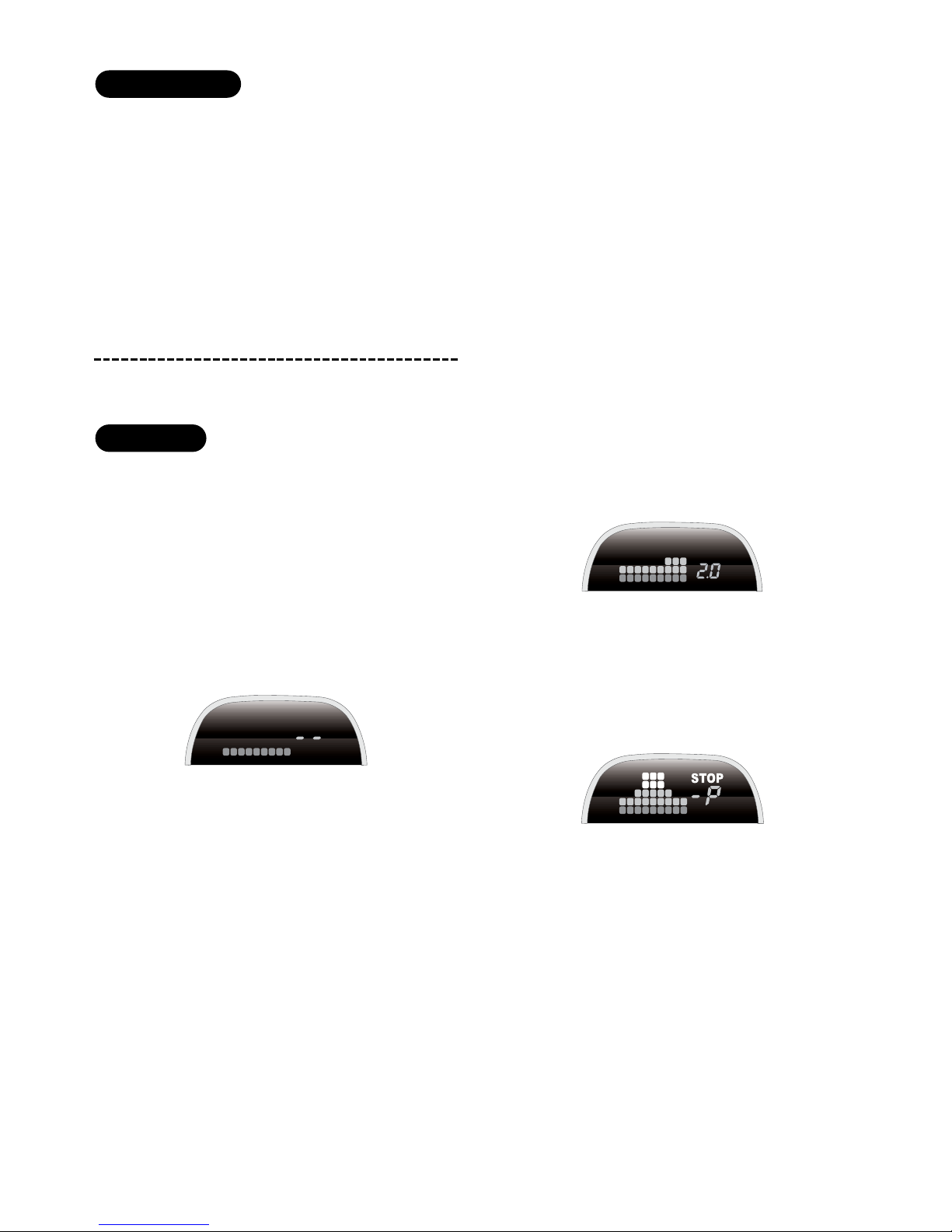
OOppeerraattiioonn
The following illustrations show the general reac-
tion of the backup system sensing and display
The system will first test all the sensors when the
reversing gear is engaged (see
Self-Test
Function
), and then the system starts sensing
objects to the rear of your vehicle.
a. The object distance is—greater than 8.5Ft:
Zone 1 Green LED of display will flash.
b. The object distance is—8.4–1Ft:
The display will show the distance by the
digital number displayed and show the
object's location in the Matrix LED Display.
c When the object distance is—less than 1Ft:
"-P" will be displayed and "Stop" will flash.
IInnttrroodduuccttiioonn
TToooollss RReeqquuiirreedd
Page 3
33
© 2005 Directed Electronics, all rights reserved
N9405T 11-05
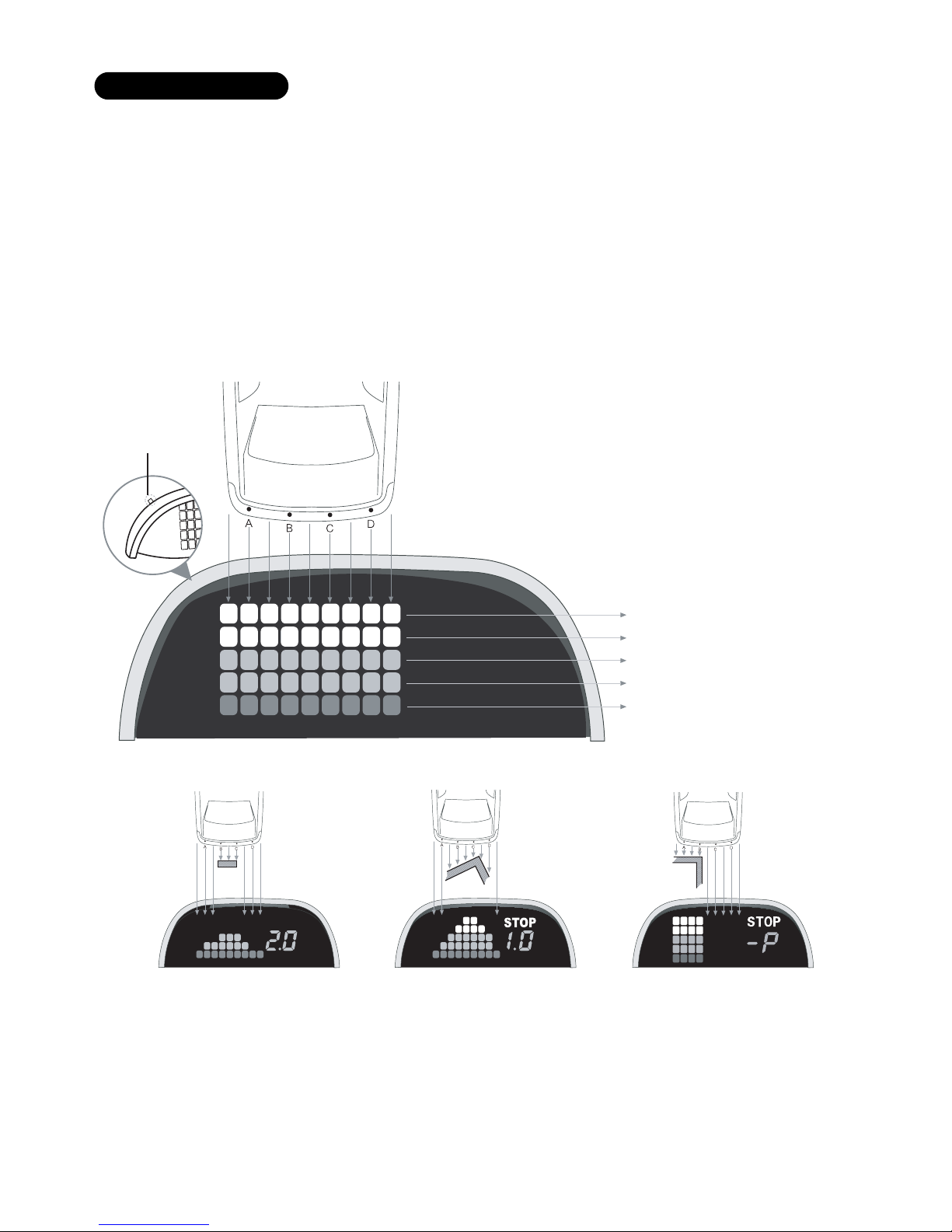
The illustrations below show the LED display
when detecting different shaped objects.
The volume switch located at the top left of the
display has three settings. This switch has the
following options.
z Beeps only, low volume
zz Beeps with voice, low volume
zzz Beeps with voice, high volume
DDiiggiittaall MMaattrriixx LLEEDD DDiissppllaayy
Volume switch
1Ft, Zone 5 (Red LED)
1.0–1.9Ft, Zone 4 (Red LED)
2.0–2.8Ft, Zone 3 (Orange LED)
2.9–4.8Ft, Zone 2 (Orange LED)
4.9–8.4Ft, Zone 1 (Green LED)
Page 4

44
© 2005 Directed Electronics, all rights reserved
N9405T 11-05
As your vehicle backs up towards an object, the
beep warning will first be none when the object
is beyond 8.4 feet away. Then, it will start
beeping at short intervals. As you get closer to
the object the beeps will lengthen until it
becomes a constant tone. Stop the vehicle, you
are now at less than 1 foot from the object. If the
volume switch is on a voice support position, the
distance and stop command will also be
announced as you back up.
DDiiggiittaall MMaattrriixx NNuummeerriicc DDiissppllaayy
NNOOTTEE::
Initially the system will beep when the vehicle is
put into reverse.
Audio warning Distance on display LED matrix display
1.0 ft
1.0~2.8 ft
-P
Zone 5
Zone 4Zone 5
Zone 2Zone 3
2.9~4.8 ft
4.9~8.4 ft
8.4ft~1.0 ft
The digital number
on display will show
every 0.1M change
of distance
Zone 1
Page 5

55
© 2005 Directed Electronics, all rights reserved
N9405T 11-05
Detection errors may occur due to the following
cases:
Smooth sloping surface
Smooth round object
Items absorbing sound, e.g. cotton
1. Heavy rain or snow, a contaminated or
damaged sensor(s) could result in detection
errors.
2. Check to ensure the system is in order before
use.
3. Clean sensors of any mud or debris.
Immediately replace any damaged sensor
when detected by the system.
4. Do not paint over the sensors as this will
affect the systems performance and accuracy.
5. Heavy smoke or vapor from exhaust, due to a
cold start or a poorly running engine can also
result is a false reading.
The back-up system only activates when the
vehicle is placed in reverse gear. When placed in
reverse gear the system first does a diagnostic
check to ensure the system is fully functional and
reports any sensor malfunctions within the back-
up system.
If all the sensors are normal, the system will beep
once and the LED display will flash once.
If there is any malfunction with the sensors, the
system will beep 3-times to indicate that one or
more sensors have problems. The flashing red
LED(s) will indicate which sensor(s) is malfunc-
tioning.
SSeellff--TTeesstt FFuunnccttiioonnFFaallssee RReeaaddiinnggss
The flashing LED indicates the problem sensor
The total number of the problem sensors
Sensor A has problem (E1: 1 problem sensor)
Sensor A,D have problem (E2: 2 problem sensors)
Page 6

1. Verify that the size of the supplied hole saw
is compatible to the diameter of the sensor
before drilling your bumper. Use a scrap piece
of wood for this test.
NNoottee::
Before drilling any holes in the vehicle ensure
that the the area behind is clear of any electrical,
hydraulic, or support members, etc.
2. Install the sensor vertically, the "up" arrow
must be pointing up.
3. Each sensor is numbered, ensure that they are
installed as shown on the illustration.0
SSeennssoorr IInnssttaallllaattiioonn
66
© 2005 Directed Electronics, all rights reserved
N9405T 11-05
IInnssttaallllaattiioonn
NNoottee::
Before installing system let the
components of the exhaust system cool
down. This will make the installation safer
and preclude heat damage to the back up
sensor wiring or components.
The following illustration shows the general loca-
tion of the components of the back up system.
IInnssttaallllaattiioonn DDiiaaggrraamm
Display
Sensors
ECM
Connect to
reversing light(+)
Connect to
ignition wire (+)
1 foot 8 inches
~2 feet 3
inches
0.3L 0.4L 0.3L
5~8 inches 5~8 inches
Page 7

77
© 2005 Directed Electronics, all rights reserved
N9405T 11-05
EExxaammppllee SSeennssoorr PPllaacceemmeenntt CCaallccuullaattiioonn::
1. Measure the mounting distance between the
proposed locations for sensor A and sensor D.
For this example (not to be used for your
vehicle) let’s say that measures 48”.
2. Then 0.3L is 0.3 X 48” = 14.4”
and 0.4L is 0.4 X 48” = 19.2”
3. Hence, the distance that sensor B is from
sensor A is 14.4 inches, and the distance that
sendor C is from sensor D is 14.4 inches. The
distance between sensor B and C will be
19.2”.
NNOOTTEE::
These distances are approximate as mounting
locations have to be selected based on clearance behind
the bumper and any obstructions or bumper curvatures
on the surface of the bumper.
4. Drill the holes in the bumper as indicated in
the diagrams above and install the sensors.
Sensors A and D should
NNOOTT
be mounted on
the curve of the bumper.
NNoottee::
Before drilling any holes ensure the the area
behind is clear of any electrical, hydraulic, or support
members, etc.
NNoottee::
Wiring is shown and described is for a positive
reverse indicator system.
The ECU is water resistant, however, it is recom-
mended that the module be mounted in the trunk
compartment or for a truck in as much of a pro-
tected area as possible.
1. Use the 3-sheet metal screws to mount the
module.
2. Connect the white wire to reversing light(+)
EECCUU IInnssttaallllaattiioonn
1. Verify that the size of the
supplied hole saw (18.5mm)
is compatible to the diameter
of the sensor by first drilling
a test hole in a scrap piece of
wood.
sensor A
sensor B
sensor C
sensor D
ECU
white
black
GND
Mount ECU in trunk
or
for a truck in as much
of a protected
area as possible
reversing lingt(+)
UP
UP
2. Install the sensor vertically,
the "up" sign must be on
upside.
Connect the white wire
to reversing light(+)
Page 8

1. Each of the four sensor interconnecting
cables are numbered to match with the
number on the sensor cable.
2. To ensure a water resistant connection at the
sensors, the connectors should be seated so
that the O-ring on the connector is snug
against the collar of the jack before tighten-
ing the connector.
3. Run the sensor interconnecting cables up into
the trunk (or to the location of the ECU for a
truck) and connect to the ECU module. Ensure
that you connect the correct numbered sensor
lead to match the connector jack on the ECU
module (see illustration).
4. Connect the White wire to the reverse indica-
tor wire (refer to previous illustration).
5. Connect the Black wire to the vehicle’s
chassis (refer to previous illustration).
NNoottee::
Discuss with the vehicle owner the placement of
the display.
1. Connect the White wire to the (+) ignition
wire.
2. Connect the Black wire to the vehicle’s
chassis.
3. Clean the area of the dashboard where the
display is going to be mounted.
4. Remove the 3M sticker off the bottom of the
display.
5. Mount the display on the dashboard by firmly
pressing down on the display.
Use the following illustration to test and verify
the operation of the backup system.
WWaarrnniinngg::
Do not stand behind a moving
vehicle death or injury could occur. Prior
to testing, set the parking brake On,
ignition key On (not start), step foot on
brake and shift the vehicle into reverse.
AAfftteerr IInnssttaallllaattiioonn TTeesstt
DDiiggiittaall MMaattrriixx LLEEDD DDiissppllaayy
SSeennssoorr ttoo EECCUU ccaabblliinngg
88
© 2005 Directed Electronics, all rights reserved
N9405T 11-05
Black
White
Ground
Ignition
Input (+)
Page 9

99
© 2005 Directed Electronics, all rights reserved
N9405T 11-05
Ensure that the engine is not running while proceeding
with the following tests.
Test the system operation with a piece of wood
(8 inches wide x 3 feet, 3 inches high) after the
installation. Start with the wood more than 8.4
feet away from the vehicle. Then move the wood
closer to the vehicle and ensure that both the
audible, LED, and distance indicators display cor-
rectly.
No beep at power up or no LEDs flashing
1. Is power wire connected to ECU correctly?
2. Verify (+)12V at ECU when vehicle is in
reverse.
3. Verify the ground connection
4. Have you connected to the correct reversing
indicator wire?
5. Do you have a minimum of (+)12V and ground
at the display?
False warning tone or false LED flashing
1. Is the sensor mounted too low or pointing to
the ground?
Sensors do not detect any objects
1. Is the vehicle’s exhaust smoking? Correct or
allow it to clear before proceeding with
testing.
2. Are sensors properly plugged into the correct
sockets?
If the problem persists, please follow these steps:
1. For consumers: Contact your dealer
2. For Installer or dealer:
a. Replace the ECU and re-check the system.
b. Test the sensors with a known operative
ECU and retest using the flat wooden
board.
c. Plug the known operative sensors into the
ECU and re-check.
d. Contact Directed tech support.
TTrroouubblleesshhoooottiinngg
8.4Ft
 Loading...