

Page 1

NOTE: This product is intended for installation by a professional installer only!
Any attempt to install this product by any person other than a trained professional
may result in severe damage to a vehicle’s electrical system and components.
PPrrooSSeeccuurriittyy
Model S660
installation guide
Page 2

22
Page 3

33
ttaabbllee ooff ccoonntteennttss
wwaarrnniinngg!! ssaaffeettyy ffiirrsstt .. .. .. .. .. .. .. .. .. .. .. .. .. .. .. .. .. .. .. .. .. .. .. .. 44
iinnssttaallllaattiioonn ppooiinnttss ttoo rreemmeemmbbeerr .. .. .. .. .. .. .. .. .. .. .. .. .. .. .. .. 44
before beginning the installation . . . . . . . . . . . . 4
after the installation . . . . . . . . . . . . . . . . . . . . . 4
ddeecciiddiinngg oonn ccoommppoonneenntt llooccaattiioonnss .. .. .. .. .. .. .. .. .. .. .. .. .. .. .. 55
locations for the siren . . . . . . . . . . . . . . . . . . . . 5
locations for the control module . . . . . . . . . . . . . 5
locations for stinger doubleguard shock sensor . . . 6
locations for valet/program switch . . . . . . . . . . . 7
locations for the status LED . . . . . . . . . . . . . . . . 7
locations for the optional starter kill relay . . . . . . 8
ffiinnddiinngg tthhee wwiirreess yyoouu nneeeedd .. .. .. .. .. .. .. .. .. .. .. .. .. .. .. .. .. .. .. .. 88
obtaining constant 12V . . . . . . . . . . . . . . . . . . . 8
finding the 12V switched ignition wire. . . . . . . . . 9
finding the starter wire . . . . . . . . . . . . . . . . . . . 9
finding a (+) parking light wire . . . . . . . . . . . . . 10
finding the door pin switch circuit. . . . . . . . . . . 11
mmaakkiinngg yyoouurr wwiirriinngg ccoonnnneeccttiioonnss .. .. .. .. .. .. .. .. .. .. .. .. .. .. .. 1122
pprriimmaarryy hhaarrnneessss ((HH11)),, 1122--ppiinn ccoonnnneeccttoorr .. .. .. .. .. .. .. .. .. .. 1133
aauuxxiilliiaarryy hhaarrnneessss ((HH22)),, 66--ppiinn ccoonnnneeccttoorr .. .. .. .. .. .. .. .. .. .. 1133
ddoooorr lloocckk hhaarrnneessss,, 33--ppiinn ccoonnnneeccttoorr .. .. .. .. .. .. .. .. .. .. .. .. .. 1144
rriibbbboonn hhaarrnneessss,, wwiirriinngg ddiiaaggrraamm .. .. .. .. .. .. .. .. .. .. .. .. .. .. .. .. 1144
pprriimmaarryy hhaarrnneessss ((HH11)) wwiirree ccoonnnneeccttiioonn gguuiiddee .. .. .. .. .. .. .. 1155
sseeccoonnddaarryy hhaarrnneessss ((HH22)) wwiirree ccoonnnneeccttiioonn gguuiiddee .. .. .. .. .. 2200
pplluugg--iinn LLEEDD aanndd vvaalleett//pprrooggrraamm sswwiittcchh .. .. .. .. .. .. .. .. .. .. .. 2222
pprrooggrraammmmeerr iinntteerrffaaccee,, 33--ppiinn bbllaacckk pplluugg .. .. .. .. .. .. .. .. .. .. 2222
sshhoocckk sseennssoorr hhaarrnneessss,, 44--ppiinn ccoonnnneeccttoorr .. .. .. .. .. .. .. .. .. .. .. 2233
pprrooggrraammmmiinngg jjuummppeerrss .. .. .. .. .. .. .. .. .. .. .. .. .. .. .. .. .. .. .. .. .. .. 2244
light flash (+)/(-) . . . . . . . . . . . . . . . . . . . . . . 24
ttrraannssmmiitttteerr//rreecceeiivveerr lleeaarrnn rroouuttiinnee™™ .. .. .. .. .. .. .. .. .. .. .. .. .. 2244
ttrraannssmmiitttteerr ccoonnffiigguurraattiioonnss .. .. .. .. .. .. .. .. .. .. .. .. .. .. .. .. .. .. .. 2266
standard configuration . . . . . . . . . . . . . . . . . . . 26
mmuullttii--lleevveell sseeccuurriittyy aarrmmiinngg .. .. .. .. .. .. .. .. .. .. .. .. .. .. .. .. .. .. .. 2288
ssyysstteemm ffeeaattuurreess lleeaarrnn rroouuttiinnee .. .. .. .. .. .. .. .. .. .. .. .. .. .. .. .. .. 2288
ffeeaattuurree mmeennuuss.. .. .. .. .. .. .. .. .. .. .. .. .. .. .. .. .. .. .. .. .. .. .. .. .. .. .. .. 3300
menu #1 - basic features . . . . . . . . . . . . . . . . . 30
menu #2 - advanced features . . . . . . . . . . . . . . 31
ffeeaattuurree ddeessccrriippttiioonnss.. .. .. .. .. .. .. .. .. .. .. .. .. .. .. .. .. .. .. .. .. .. .. .. 3311
menu #1 - basic features . . . . . . . . . . . . . . . . . 31
menu #2 - advanced features . . . . . . . . . . . . . . 33
nnuuiissaannccee pprreevveennttiioonn cciirrccuuiittrryy™™ .. ..
.. .. .. .. .. .. .. .. .. .. .. .. .. .. 3355
vvaalleett mmooddee .. .. .. .. .. .. .. .. .. .. .. .. .. .. .. .. .. .. .. .. .. .. .. .. .. .. .. .. .. .
. 3355
ttaabbllee ooff zzoonneess.. .. .. .. .. .. .. .. .. .. .. .. .. .. .. .. .. .. .. .. .. .. .. .. .. .. .. .. 3366
lloonngg tteerrmm eevveenntt hhiissttoorryy .. .. .. .. .. .. .. .. .. .. .. .. .. .. .. .. .. .. .. .. .. 3366
ttrroouubblleesshhoooottiinngg .. .. .. .. .. .. .. .. .. .. .. .. .. .. .. .. .. .. .. .. .. .. .. .. .. .. 3377
alarm troubleshooting . . . . . . . . . . . . . . . . . . . 37
wwiirriinngg qquuiicckk rreeffeerreennccee gguuiiddee .. .. .. .. .. .. .. .. .. .. .. .. .. .. .. .. .. .. 3388
Page 4

44
wwaarrnniinngg!! ssaaffeettyy ffiirrsstt
The following safety warnings must be observed at all times:
■ Due to the complexity of this system, installation of this product must only be performed by an authorized
Ungo dealer.
iinnssttaallllaattiioonn ppooiinnttss ttoo rreemmeemmbbeerr
■ Please read this entire installation guide before beginning the installation. The installation of this remote
start system requires interfacing with many of the vehicle’s systems. Many new vehicles use low-voltage or
multiplexed systems that can be damaged by low resistance testing devices, such as test lights and logic
probes (computer safe test lights). Test all circuits with a high quality digital multi-meter before making con-
nections.
■ Do not disconnect the battery if the vehicle has an anti-theft-coded radio. If equipped with an air bag, avoid
disconnecting the battery if possible. Many airbag systems will display a diagnostic code through their
warning lights after they lose power. Disconnecting the battery requires this code to be erased, which can
require a trip to the dealer.
■ Check with the customer on status LED location.
■ Remove the domelight fuse. This prevents accidentally draining the battery.
■ Roll down a window to avoid being locked out of the car.
■ Test all functions. The “Using Your System” section of the Owner's Guide is very helpful when testing.
■ When testing, don’t forget that this system is equipped with Nuisance Prevention Circuitry™(NPC™). NPC can
bypass trigger zones, making them appear to stop working. See the
Nuisance Prevention Circuitry
section.
■ Review and complete the
Safety Check
section of this guide prior to the vehicle reassembly.
aafftteerr tthhee iinnssttaallllaattiioonn
bbeeffoorree bbeeggiinnnniinngg tthhee iinnssttaallllaattiioonn
Page 5
55
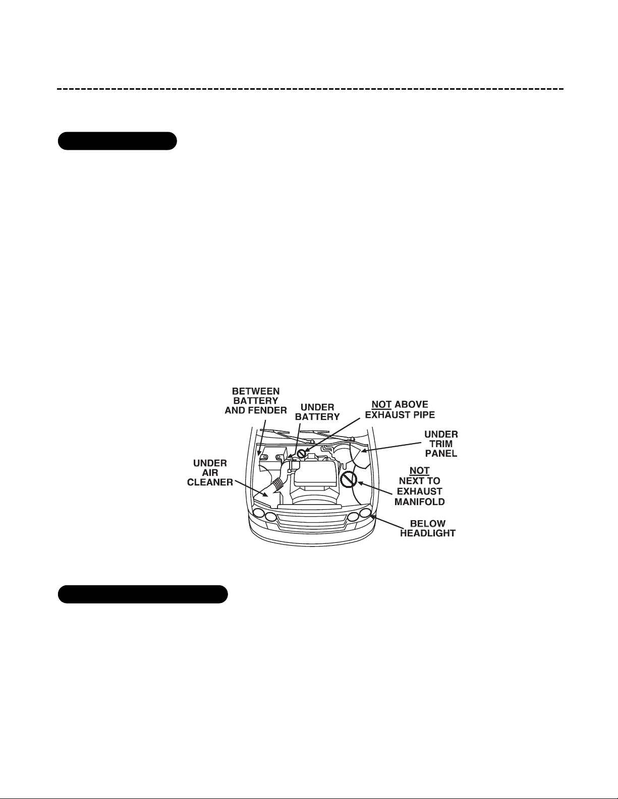
ddeecciiddiinngg oonn ccoommppoonneenntt llooccaattiioonnss
SSoommee tthhiinnggss ttoo rreemmeemmbbeerr aabboouutt mmoouunnttiinngg tthhee ssiirreenn::
■ Keep it away from heat sources, such as radiators, exhaust manifolds, turbochargers, and heat shields.
■ Mount it where a thief cannot easily disconnect it, whether the hood is open or shut. Both the siren and its
wires should be difficult to find. This usually involves disguising the wire to look like a factory harness.
■ We recommend against grounding the siren to its mounting screws. Instead, we recommend running both the
red and black wires into the passenger compartment and grounding to one common point for all devices.
After all, both wires are the same length and come already bonded together. Whenever possible, conceal your
wires in the factory harnesses or in the same style loom as the factory.
■ When possible, place the siren on the same side of the vehicle as the control module, where its wires will
reach the control module’s wires without extending them. Always run the wires through the center of a
grommet, never through bare metal!
■ Point the siren down so water does not collect in it.
SSoommee tthhiinnggss ttoo rreemmeemmbbeerr aabboouutt wwhheerree tto
o mmoouunntt tthhee ccoonnttrrooll mmoodduullee::
■ Never put the control module in the engine compartment!
■ The first step in hot-wiring a vehicle is removing the driver's side under-dash panel to access the starter and
ignition wires. If the control module is placed just behind the driver's side dash it can easily be disconnected.
■ When mounting the control module, try to find a secure location that will not require you to extend the harnesses’
wires (they are 1.5 meters long). Keep it away from the heater core (or any other heat sources) and any obvious leaks.
llooccaattiioonnss ffoorr tthhee ccoonnttrrooll mmoodduullee
llooccaattiioonnss ffoorr tthhee ssiirreenn
Page 6
66
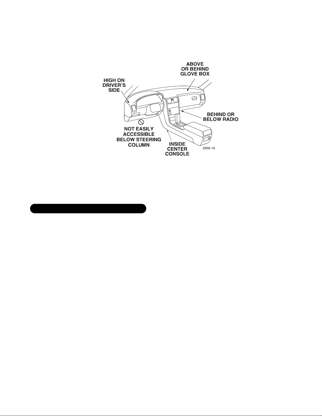
■ The higher the control module is in the vehicle, the better the transmitter range will be. If you put the
control module under a seat or inside a metal dashboard, range will diminish.
Some good control module locations: above the glove box, inside the center console, above the under-dash fuse
box, above the radio, etc.
SSoommee tthhiinnggss ttoo rreemmeemmbbeerr aabboouutt wwhheerree ttoo mmoouunntt tthhee sshhoocckk sseennssoorr::
■ Never put the Stinger
®
in the engine compartment!
■ Find a spot close to the control module so that the wires do not need to be extended. Keep it away from the
heater core (or any other heat sources) and any obvious leaks.
HHooww tthhee SSttiinnggeerr
®®
iiss mmoouunntteedd iiss tthhee mmoosstt iimmppoorrttaanntt ffaaccttoorr iinn iittss ppeerrffoorrmmaannccee.. WWee rreeccoommmmeenndd ttwwoo mmeetthhooddss::
■ Using double-sided tape or hook-and-loop fastener to mount to a trim panel or an air duct, or
■ Wire-tying to a wire harness.
If mounting the sensor where it cannot be easily reached for adjustment, hook-and-loop fastening tape (such as
Velcro) is recommended for ease of removal for future adjustments.
NNOOTTEE::
In many vehicles, tying the sensor to a steering column or screwing it to metal will result
in poor sensitivity, especially at the rear of the vehicle.
llooccaattiioonnss ffoorr ssttiinnggeerr ddoouubblleegguuaarrdd sshhoocckk sseennssoorr
Page 7
77
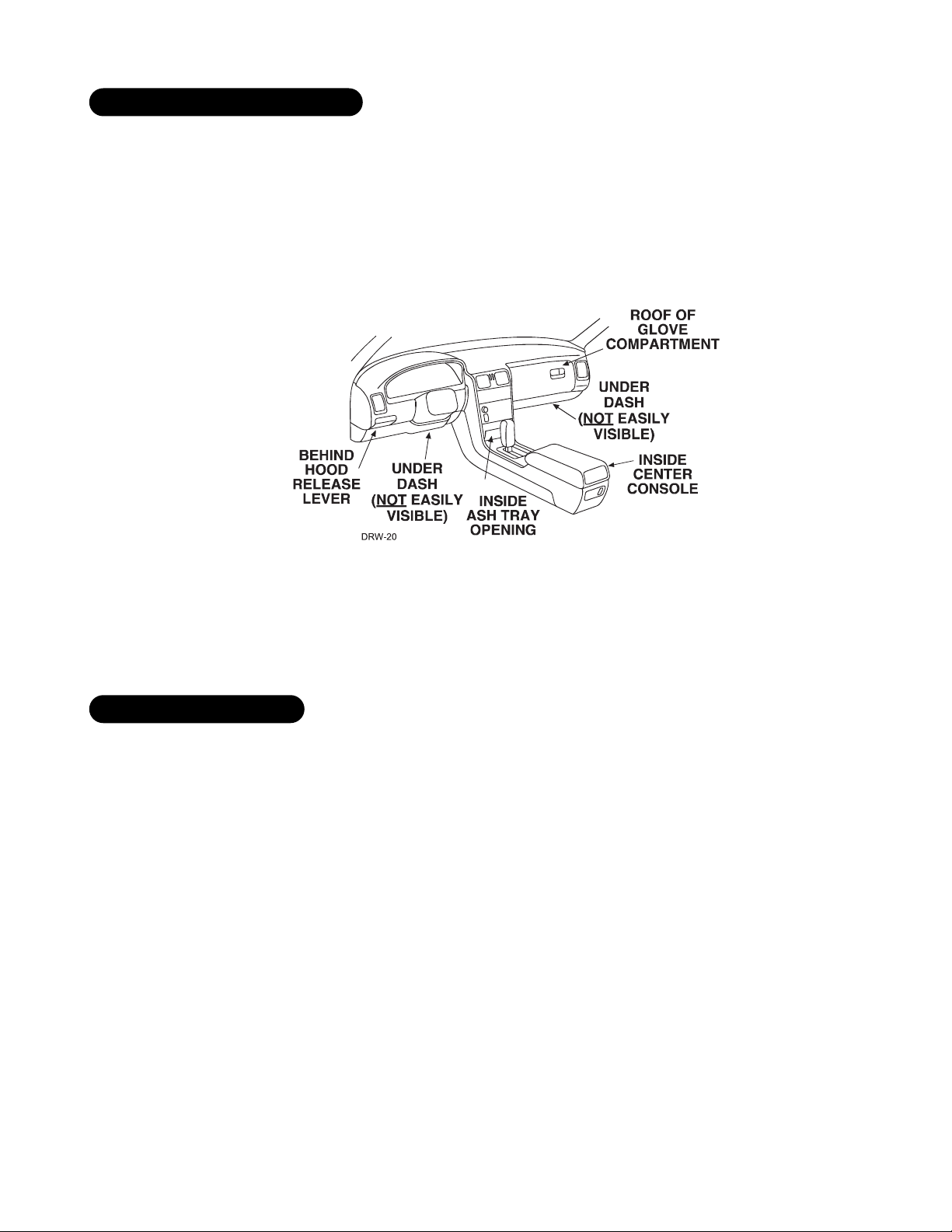
IIMMPPOORRTTAANNTT!!
When the vehicle is delivered, please show the user where this switch is located
and how to disarm the system with it.
Ensure that the location you pick for the switch has sufficient clearance to the rear. The switch should be well
hidden. It should be placed so passengers or stored items (such as in a glove box or center console) cannot acci-
dentally hit it. The switch fits into a
9
/32-inch hole.
This system has Remote Valet. The user can enter and exit Valet® Mode without having to reach the
Valet®/Program switch. This feature was introduced so that switch location was less critical in day-to-day use.
As long as the Valet®/Program switch can be reached to disarm without a transmitter, easy access is not important.
TThhiinnggss ttoo rreemmeemmbbeerr wwhheenn ppoossiittiioonniinngg tthhee SSttaattuuss LLEEDD::
■ It should be visible from both sides and the rear of the vehicle, if possible.
■ It needs at least
1
/2-inch clearance to the rear.
■ It is easiest to remove a small panel, such as a switch blank or a dash bezel, before drilling a
9
/32-inch hole.
■ Use quick-disconnects near the LED wires if the panel is removable. This lets mechanics or other installers
remove the panel without cutting the wires.
llooccaattiioonnss ffoorr tthhee ssttaattuuss LLEEDD
llooccaattiioonnss ffoorr vvaalleett//pprrooggrraamm sswwiittcchh
Page 8
88
If optional starter kill relay or its connections are immediately visible upon removal of the under-dash panel,
they can easily be bypassed. Always make the relay and its connections difficult to discern from the factory
wiring! Exposed yellow butt connectors do not look like factory parts, and will not fool anyone! For this reason,
routing the optional starter kill wires away from the steering column is recommended.
ffiinnddiinngg tthhee wwiirreess yyoouu nneeeedd
Now that you have decided where each component will be located, you’re going to find the wires in the car that
the security system will be connected to.
IIMMPPOORRTTAANNTT!!
Do not use a 12V test light or logic probe (computer safe test light) to find these
wires! Use a digital multimeter for all testing.
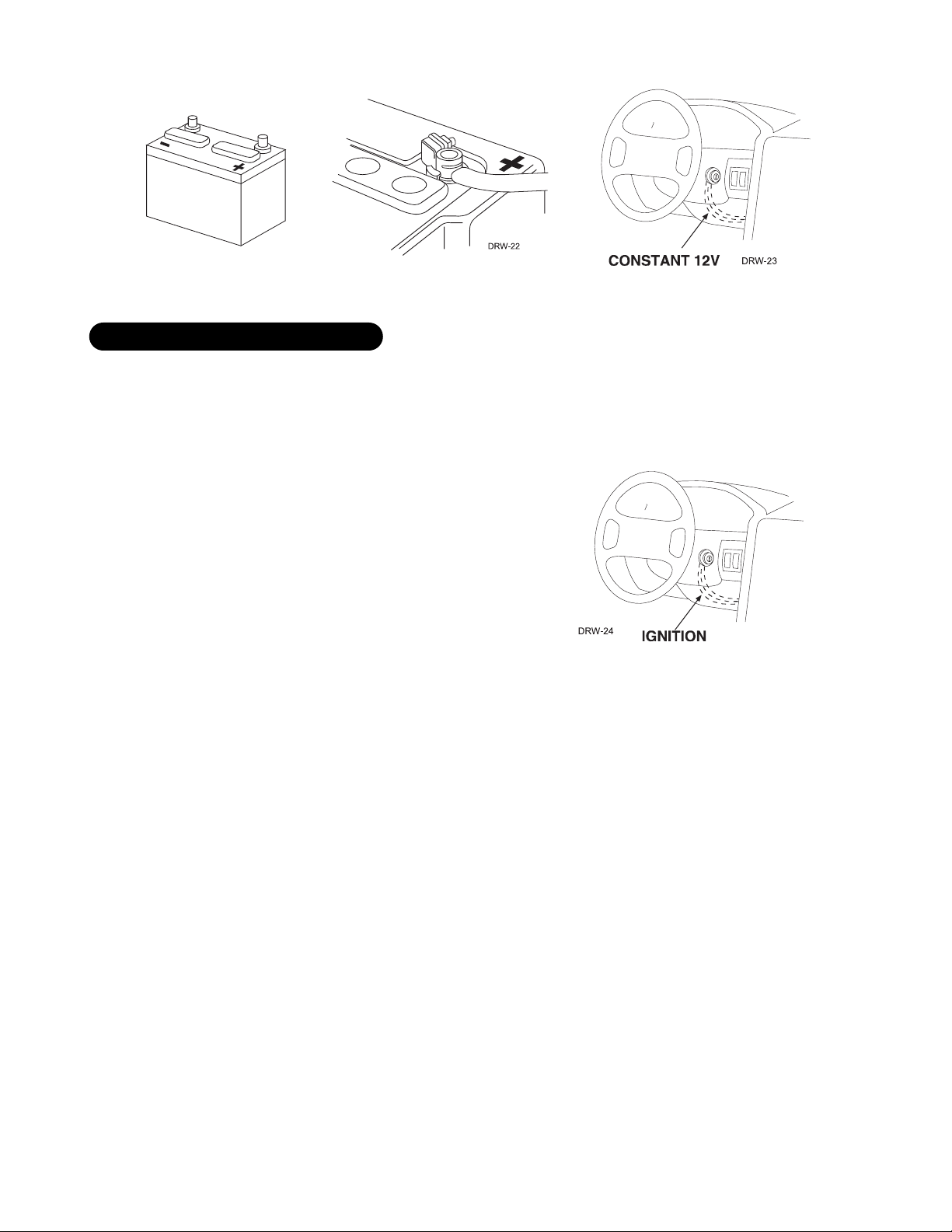
We recommend two possible sources for 12V constant: the (+) terminal of the battery, or the constant supply to
the ignition switch. Always install a fuse within 12 inches of this connection. If the fuse also will be powering
other circuits, such as door locks, a power window module, a Nite-Lite® headlight control system, etc., fuse
accordingly.
IIMMPPOORRTTAANNTT!!
Do not remove the fuse holder on the red wire. It ensures that the control module
has its own fuse, of the proper value, regardless of how many accessories are added to the main
power feed.
oobbttaaiinniinngg ccoonnssttaanntt 1122VV
llooccaattiioonnss ffoorr tthhee ooppttiioonnaall ssttaarrtteerr kkiillll rreellaayy
Page 9
99
The ignition wire is powered when the key is in the run or start position. This is because the ignition wire powers
the ignition system (spark plugs, coil) as well as the fuel delivery system (fuel pump, fuel injection computer).
Accessory wires lose power when the key is in the start position to make more current available to the starter motor.
HHooww ttoo ffiinndd ((++))1122VV iiggnniittiioonn wwiitthh yyoouurr mmuullttiimmeetteerr::
1. Set to DCV or DC voltage (12V or 20V is fine).
2. Attach the (-) probe of the meter to chassis ground.
3. Probe the wire you suspect of being the ignition wire. The
steering column harness or ignition switch harness is an excel-
lent place to find this wire.
4. Turn the ignition key switch to the run position. If your meter
reads (+)12V, go to the next step. If it doesn’t, probe another
wire.
5. Now turn the key to the start position. The meter display should stay steady, not dropping by more than a
few tenths of a volt. If it drops close to or all the way to zero, go back to Step 3. If it stays steady at (+)12V,
you have found an ignition wire.
ffiinnddiinngg tthhee 1122VV sswwiittcchheedd iiggnniittiioonn wwiirree
Page 10
1100
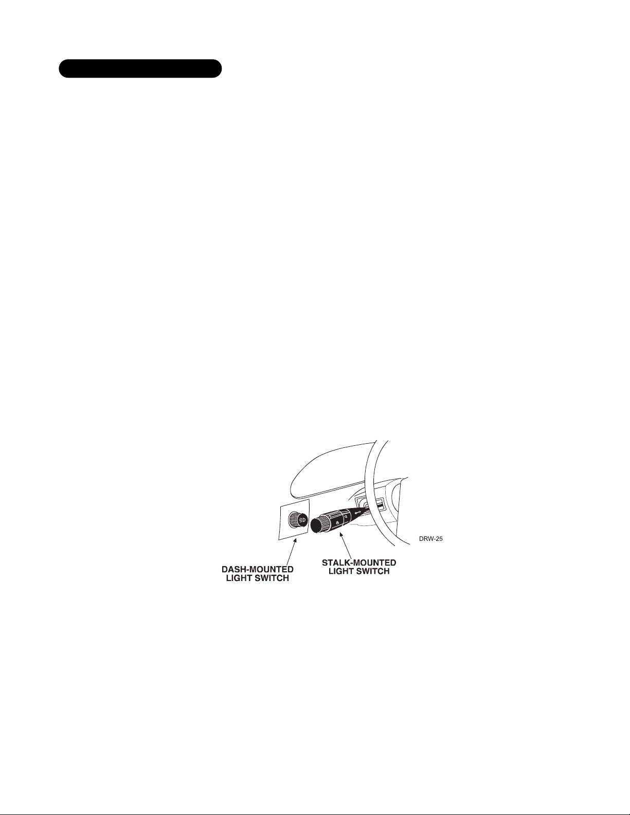
The (+) parking light wire is often found near the switch. Many cars have the switch built into the turn signal
lever, and in these cars the parking light wire can be found in the steering column. The same wire is often avail-
able in the kick panel or running board.
NNOOTTEE::
Many Toyotas, as well as many other Asian vehicles, send a (-) signal from the switch to
a relay. The relay then sends (+)12V to the bulbs. Whenever you have difficulty finding a (+)
parking light wire near the switch, simply test the wires at any switch or control panel which is
lit by the instrument panel lighting. Remember, you need a (+) parking light wire that does not
vary with the dimmer setting.
HHooww ttoo ffiinndd aa ((++)) ppaarrkkiinngg lliigghhtt ffllaasshh wwiirree wwiitthh yyoouurr mmuullttiimmeetteerr::
1. Set to DCV or DC voltage (12V or 20V is fine).
2. Attach the (-) probe of the meter to chassis ground.
3. Probe the wire you suspect of being the parking light wire. Usually, the area near the headlight/parking light
switch is an excellent area to start, as is the kick panel.
4. Turn on the parking lights. If your meter shows (+)12V, turn off the parking lights and make sure it goes back
to zero.
5. If it does return to zero, turn the parking lights back on and, using the dash light dimmer control, turn the
brightness of the dash lights up and down. If the meter changes more than a volt when using the dimmer,
look for another wire. If it stays relatively close to (+)12V, you have found your parking light wire.
ffiinnddiinngg aa ((++)) ppaarrkkiinngg lliigghhtt wwiirree
Page 11

1111
TThhee bbeesstt ppllaacceess ttoo ffiinndd tthhee ddoooorr sswwiittcchh wwiirree aarree::
■ At the pin switch: When testing at the pin switch, check the wire to ensure that it “sees” all the doors. Often,
the passenger switch will cover all the doors even if the driver’s switch will not.
■ At the dome light: This may not be your best choice if the vehicle has delayed domelight supervision, but it
will work in many Hondas, or any vehicle with completely diode-isolated pin switches.
Once you have determined the wire color, the easiest place to connect to the wire is often at the kick panel, at
the windshield pillar, or in the running board. When an easy location is not available, running a wire to the dome-
light itself is often the best solution.
HHooww ttoo ffiinndd aa ddoooorr ppiinn sswwiittcchh ttrriiggggeerr wwiirree
wwiitthh yyoouurr mmuullttiimmeetteerr::
1. Set to DCV or DC voltage (12V or 20V is fine).
2. In most Fords, fasten the (-) probe of the meter to chassis ground. In most other cars, fasten the (+) probe
of your meter to (+)12V constant.
3. Probe the wire you suspect of being the door trigger wire. If the meter reads (+)12V when any door
is opened, you have found a trigger wire.
NNOOTTEE::
Make sure the wire you use “sees” all the doors! Some newer GM vehicles lack standardtype pin switches. The dome light in these vehicles is turned on when the door handle is lifted.
These usually have a blue/white or white wire coming out of the door into the kick panel which
will provide a (-) trigger for all doors. Some GM vehicles (some Cavaliers, Grand Ams, etc.) have
a yellow wire coming out of the door which provides a (+) door trigger.
ffiinnddiinngg tthhee ddoooorr ppiinn sswwiittcchh cciirrccuuiitt
Page 12

1122
mmaakkiinngg yyoouurr wwiirriinngg ccoonnnneeccttiioonnss
Before making your connections, plan how your wires will be routed through the vehicle. For instance, the red
12V constant input and the orange ground-when-armed output (for the optional starter kill relay) will often be
routed together to the ignition switch harness. In order to keep the wiring neat and make it harder to find, you
may wish to wrap these wires together in electrical tape or conceal them in tubing similar to what the manu-
facturer used.
There are two acceptable ways of making a wire connection - solder connections and crimp connectors. When
properly performed, either type of connection is reliable and trouble-free. Regardless of whether you solder your
connections or you use mechanical-type crimp-on connections, ensure that all connections are mechanically
sound and that they are insulated.
Cheap electrical tape, especially when poorly applied, is not a reliable insulator. It often falls off in hot weather.
Use good-quality electrical tape or heat shrink.
■ Never twist-and-tape the wires together without soldering.
■ Never use “fuse taps”, as they can damage fuse box terminals.
If you use tapping connectors such as 3M T-Taps (not to be confused with Scotch-Locks), avoid using them in
higher-current applications (constant 12V, ground, etc.). Some tapping connectors are inferior in quality and
should be avoided.
Page 13

1133
pprriimmaarryy hhaarrnneessss ((HH11)),, 1122--ppiinn ccoonnnneeccttoorr
______
______
______
______
______
______
______
______
______
______
______
______
aauuxxiilliiaarryy hhaarrnneessss ((HH22)),, 66--ppiinn ccoonnnneeccttoorr
______
______
______
______
______
______
LLIIGGHHTT BBLLUUEE ((--)) SSEECCOONNDD UUNNLLOOCCKK OOUUTTPPUUTT
WWHHIITTEE//BBLLAACCKK NNOOTT UUSSEEDD
VVIIOOLLEETT//BBLLAACCKK ((--)) CCHHAANNNNEELL 55 OOUUTTPPUUTT
GGRREEEENN//WWHHIITTEE ((--)) PPRROOGGRRAAMMMMAABBLLEE CCHHAANNNNEELL 44 OOUUTTPPUUTT
GGRRAAYY//BBLLAACCKK ((--)) FFAACCTTOORRYY RREEAARRMM
LLIIGGHHTT GGRREEEENN//BBLLAACCKK ((--)) FFAACCTTOORRYY DDIISSAARRMM
HH22//11
HH22//22
HH22//33
HH22//44
HH22//55
HH22//66
RREEDD//WWHHIITTEE ((--)) 220000 mmAA CCHHAANNNNEELL 22 VVAALLIIDDIITTYY OOUUTTPPUUTT
RREEDD ((++)) CCOONNSSTTAANNTT PPOOWWEERR IINNPPUUTT
BBRROOWWNN ((++)) SSIIRREENN OOUUTTPPUUTT
EEMMPPTTYY NNOOTT UUSSEEDD
BBLLAACCKK ((--)) CCHHAASSSSIISS GGRROOUUNNDD IINNPPUUTT
VVIIOOLLEETT ((++)) DDOOOORR TTRRIIGGGGEERR IINNPPUUTT,, ZZOONNEE 33
BBLLUUEE ((--)) MMUULLTTIIPPLLEEXXEEDD IINNPPUUTT,, ZZOONNEE 44
GGRREEEENN ((--)) DDOOOORR TTRRIIGGGGEERR IINNPPUUTT,, ZZOONNEE 33
BBLLAACCKK//WWHHIITTEE ((--)) 220000 mmAA DDOOMMEELLIIGGHHTT SSUUPPEERRVVIISSIIOONN OOUUTTPPUUTT
WWHHIITTEE//BBLLUUEE NNOOTT UUSSEEDD
WWHHIITTEE ((++))//((--)) SSEELLEECCTTAABBLLEE LLIIGGHHTT FFLLAASSHH OOUUTTPPUUTT
OORRAANNGGEE ((--)) 550000 mmAA AARRMMEEDD OOUUTTPPUUTT
HH11//11
HH11//22
HH11//33
HH11//44
HH11//55
HH11//66
HH11//77
HH11//88
HH11//99
HH11//1100
HH11//1111
HH11//1122
Page 14

1144
ddoooorr lloocckk hhaarrnneessss,, 33--ppiinn ccoonnnneeccttoorr
______
______
______
rriibbbboonn hhaarrnneessss,, wwiirriinngg ddiiaaggrraamm
______
______
______
______
______
______
______
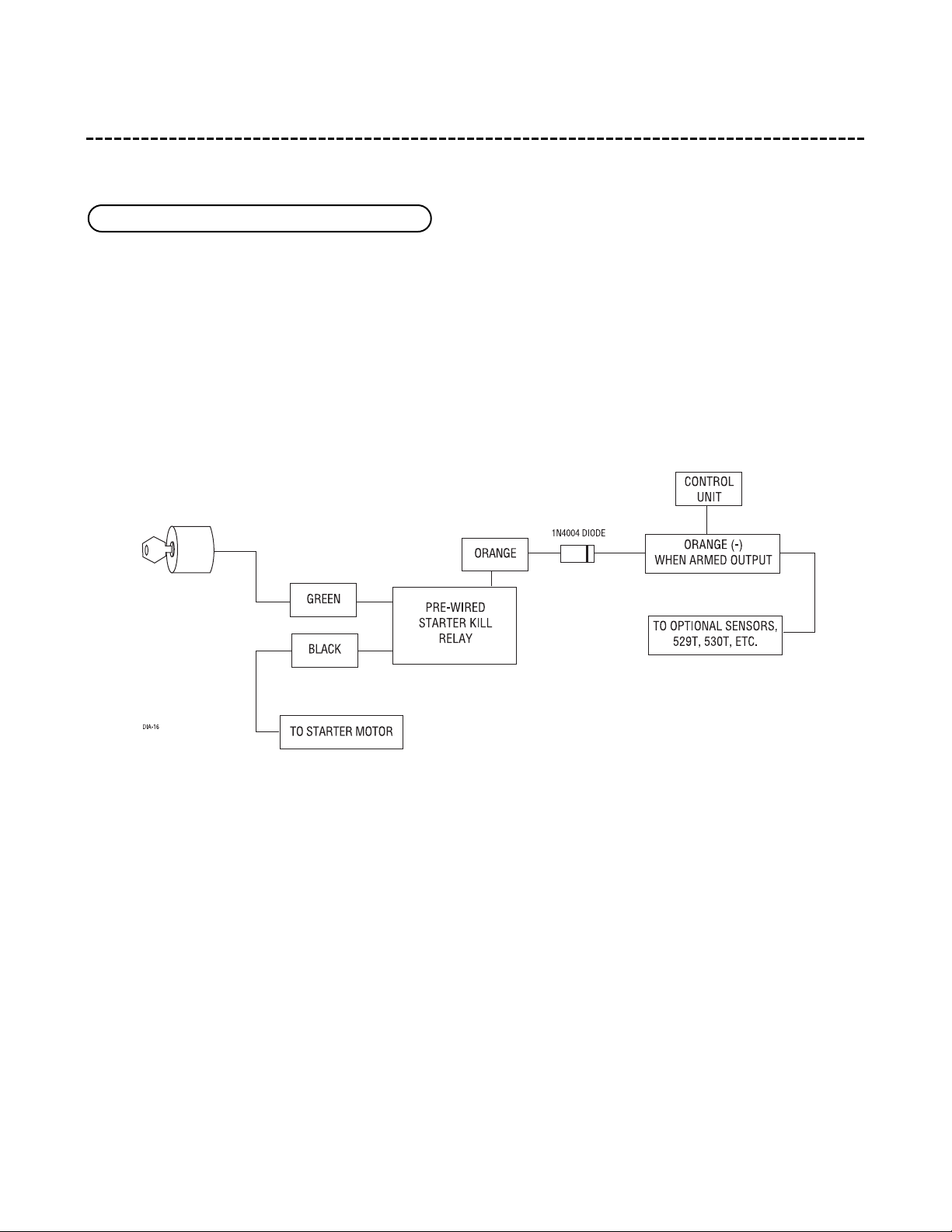
Connect this wire to the (+) 12 volt ignition wire. This wire is pre-wired to the starter kill relay and must show
(+) 12 volts with the key in the RUN position and during cranking. Take care that this wire cannot be shorted
to the chassis at any point.
YYEELLLLOOWW ((++)) iiggnniittiioonn iinnppuutt
YYEELLLLOOWW ((++)) IIGGNNIITTIIOONN IINNPPUUTT TTOO AALLAARRMM
11
22
33
44
55
66
77
BBLLUUEE ((++)) LLOOCCKK ((--)) UUNNLLOOCCKK OOUUTTPPUUTT
EEMMPPTTYY NNOOTT UUSSEEDD
GGRREEEENN ((--)) LLOOCCKK ((++)) UUNNLLOOCCKK OOUUTTPPUUTT
11
22
33
Page 15
1155
pprriimmaarryy hhaarrnneessss ((HH11)) wwiirree ccoonnnneeccttiioonn gguuiiddee
This wire supplies a (-) ground as long as the system is armed. This output ceases as soon as the system is dis-
armed. The orange wire is pre-wired to control the starter kill relay. It can supply up to 500mA of current.
NNOOTTEE::
If using the H1/1 Orange wire to activate an add-on accessory such as windo automation, pager or voice module, a 1-amp diode must be installed to ensure proper operation. Insert
the diode as shown in the following diagram.
IIMMPPOORRTTAANNTT!!
Never interrupt any wire other than the starter wire.
HH11//11 OORRAANNGGEE ((--)) ggrroouunndd--wwhheenn--aarrmmeedd oouuttppuutt
Page 16

1166
As shipped, this wire should be connected to the (+) parking light wire. If the light flash polarity jumper under
the sliding door is moved to the opposite position (see
Internal Programming Jumper
section of this guide), this
wire supplies a (-) 200 mA output. This is suitable for driving (-) light control wires in Toyota, Lexus, BMW, some
Mitsubishi, some Mazda, and other model cars.
((++)) PPoossiittiivvee LLiigghhtt FFllaasshh OOuuttppuutt
((--)) LLiigghhtt FFllaasshh OOuuttppuutt
NNOOTTEE::
For parking light circuits that draw 10 amps or more, the internal jumper must be
switched to a (-) light flash output. (See the Internal Programming Jumper section of this
guide.)
PP//NN 88661177
or a standard automotive SPDT relay must be used on the H1/2 light flash
output harness wire.
HH11//22 WWHHIITTEE ((++//--)) sseelleeccttaabbllee lliigghhtt ffllaasshh oouuttppuutt
Page 17

1177
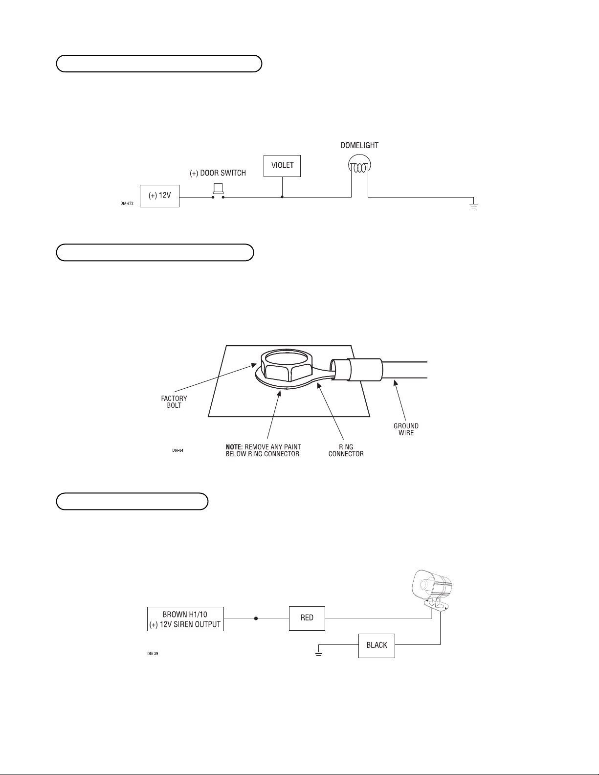
Connect this wire to the optional domelight supervision relay as shown below:
IIMMPPOORRTTAANNTT!!
This output is only intended to drive a relay. It cannot be connected directly to
the domelight circuit, as the output cannot support the current draw of one or more light bulbs.
Most vehicles use negative door trigger circuits. Connect the green wire to a wire which shows ground when any
door is opened. In vehicles with factory delays on the domelight circuit, there is usually a wire that is unaf-
fected by the delay circuitry. This wire will report Zone 3.
Inputs shorter than 0.8 seconds will trigger the Warn Away response, while inputs longer than 0.8 seconds will
trigger the full alarm sequence. If installing an optional Directed Electronics dual stage sensor, connect both
the blue and the green wires of the optional sensor to this input. This wire will report Zone 4.
HH11//66 BBLLUUEE ((--)) mmuullttiipplleexx iinnppuutt,, zzoonnee 44
HH11//55 GGRREEEENN ((--)) ddoooorr ttrriiggggeerr iinnppuutt,, zzoonnee 33
HH11//44 BBLLAACCKK//WWHHIITTEE ((--)) 220000 mmAA ddoommeelliigghhtt ssuuppeerrvviissiioonn oouuttppuutt
Page 18
1188
This wire is used in vehicles that have a positive (+) switched dome light circuit. Connect the violet wire to a
wire that shows (+)12V when any door is opened, and ground when the door is closed. This wire will report Zone 3.
Remove any paint and connect this wire to bare metal, preferably with a factory bolt rather than your own screw.
(Screws tend to either strip or loosen with time.) We recommend grounding all your components, including the
siren, to the same point in the vehicle.
Connect this to the red wire of the siren. Connect the black wire of the siren to (-) chassis ground, preferably at
the same point you connected the control module’s black ground wire.
HH11//1100 BBRROOWWNN ((++)) ssiirreenn oouuttppuutt
HH11//88 BBLLAACCKK ((--)) cchhaassssiiss ggrroouunndd ccoonnnneeccttiioonn
HH11//77 VVIIOOLLEETT ((++)) ddoooorr ttrriiggggeerr iinnppuutt,, zzoonnee 33
Page 19

1199
Before connecting this wire, remove the supplied fuse. Connect to the battery positive terminal or the constant
12V supply to the ignition switch.
NNOOTTEE::
Always use a fuse within 12 inches of the point you obtain (+)12V. Do not use the 15A
fuse in the harness for this purpose. This fuse protects the module itself.
When the system receives the code controlling Channel 2, for longer than 1.5 seconds, the red/white wire will
supply an output as long as the transmission continues. This is often used to operate a trunk/hatch release or
other relay-driven function.
IIMMPPOORRTTAANNTT!!
Never use this wire to drive anything but a relay or a low-current input! The transistorized output can only supply 200 mA of current. Connecting directly to a solenoid, motor,
or other high-current device will cause it to fail.
HH11//1122 RREEDD//WWHHIITTEE cchhaannnneell 22,, 220000mmAA ((--)) oouuttppuutt
HH11//1111 RREEDD ((++))1122VV ccoonnssttaanntt ppoowweerr iinnppuutt
Page 20

2200
sseeccoonnddaarryy hhaarrnneessss ((HH22)) wwiirree ccoonnnneeccttiioonn gguuiiddee
This wire sends a negative pulse every time the remote start is activated or the doors are unlocked. This can be
used to pulse the disarm wire of the vehicle's factory anti-theft device. Use a relay to send a (-) or (+) pulse to
the disarm wire as shown in the following diagrams.
RReellaayy ffoorr NNeeggaattiivvee ((--)) DDiissaarrmm WWiirree RReellaayy ffoorr PPoossiittiivvee ((++)) DDiissaarrmm WWiirree
This wire sends a negative pulse every time the remote start shuts down or the doors are locked. This can be
used to pulse the arm wire of the vehicle's factory anti-theft device. Use a relay to send a (-) or (+) pulse to the
arm wire.
This wire provides 200 mA programmable output. (See
Feature Descriptions
section of this guide.)
IIMMPPOORRTTAANNTT!!
Never use this wire to drive anything but a relay or a low-current input! This transistorized output can only supply 200 mA, and connecting directly to a solenoid, motor, or other
high-current device will cause the module to fail.
HH22//44 VVIIOOLLEETT//BBLLAACCKK cchhaannnneell 55 oouuttppuutt
HH22//33 GGRREEEENN//WWHHIITTEE 220000 mmAA ((--)) pprrooggrraammmmaabbllee cchhaannnneell 44 oouuttppuutt
HH22//22 GGRRAAYY//BBLLAACCKK ffaaccttoorryy aallaarrmm rreeaarrmm
HH22//11 LLIIGGHHTT GGRREEEENN//BBLLAACCKK ((--)) ffaaccttoorryy ddiissaarrmm oouuttppuutt
Page 21

2211
Connect this wire to the wire in the vehicle that sends the signal to turn on the WAIT-TO-START bulb in the dash-
board. In most diesels the wire is negative (ground turns on the bulb) and the GRAY/BLACK wire can be directly
connected to the wire in the vehicle. If the vehicle uses a positive wire (12V to turn on the bulb) a relay must
be used to change the polarity. (See
Finding the Wires You Need
section of this guide.) Here are some common
colors of this wire:
■ Chevrolet and GMC trucks - Light blue or dark blue
■ Ford Trucks - Black/pink
■ Dodge Ram Trucks - Orange/black or black/orange
NNOOTTEE!!
A 1-amp diode must be installed in line on the factory wire between the wait-to-start
indicator and the ECM. (See the following diagram for details.)
This wire provides a second unlock output for progressive locks. Refer to document 1041—
Door Locking System
Wiring Guide
for specific applications.
HH22//66 LLIIGGHHTT BBLLUUEE ((--)) 220000mmAA 22nndd uunnlloocckk oouuttppuutt
HH22//55 WWHHIITTEE//BBLLAACCKK ((--)) ddiieesseell wwaaiitt--ttoo--ssttaarrtt bbuullbb iinnppuutt
Page 22

2222
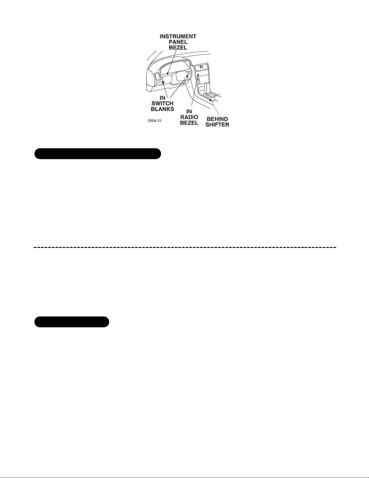
pplluugg--iinn LLEEDD aanndd vvaalleett//pprrooggrraamm sswwiittcchh
These plug into the module. The Status LED plugs into the small two-pin socket, while the Valet® /Program
Switch should be plugged into the larger blue two-pin connector. The Status LED fits into a
9
/32-inch hole.
SSttaattuuss LLEEDD VVaalleett®®//PPrrooggrraamm SSwwiittcchh
pprrooggrraammmmeerr iinntteerrffaaccee,, 33--ppiinn bbllaacckk pplluugg
The black 3-pin port is provided for programming of the unit. The unit can also be programmed using the
ProSecurity Programmer. When using the ProSecurity Programmer, it is possible to configure any and all of the
programmable functions as well as lock the Transmitter/Receiver and System Features Learn Routines so that
unauthorized users cannot change the configuration or program transmitters to the unit.
When the learn routines have previously been programmed using the ProSecurity Programmer, they may
have been locked. Before proceeding with reprogramming the learn routines, they must be unlocked with
the ProSecurity Programmer - this cannot be done manually with the Valet switch.
DIA-41
Page 23

2233
sshhoocckk sseennssoorr hhaarrnneessss,, 44--ppiinn ccoonnnneeccttoorr
Inputs shorter than 0.8 seconds will trigger the Warn Away® response, while inputs longer than 0.8 seconds will
trigger full alarm sequence and report Zone Two. If installing an optional Directed Electronics dual stage sensor,
connect to the green wire as shown below. The diagram below eliminates the need for diodes to isolate the
sensors.
DDiiaaggrraamm ffoorr aaddddiinngg ooppttiioonnaall DDiirreecctteedd EElleeccttrroonniiccss dduuaall ssttaaggee sseennssoorr ttoo ggrreeeenn wwiirree ((ZZoonnee 22))::
Inputs shorter than 0.8 seconds will trigger the Warn Away® response, while inputs longer than 0.8 seconds will
trigger full alarm sequence and will also report Zone Two.
Do not use these for anything besides the plug-in shock sensor.
RREEDD aanndd BBLLAACCKK:: RREEDD iiss ((++))1122VV ccoonnssttaanntt,, BBLLAACCKK iiss ((--)) ggrroouunndd
BBLLUUEE ((--)) mmuullttiipplleexx iinnppuutt,, zzoonnee 22
GGRREEEENN ((--)) mmuullttiipplleexx iinnppuutt,, zzoonnee 22
Page 24

2244
pprrooggrraammmmiinngg jjuummppeerrss
This jumper is used to determine the light flash output. In the (+) position, the on-board relay is enabled and
the unit will output (+)12V on the WHITE wire, H1/2. In the (-) position, the on-board relay is disabled. The
WHITE wire, H1/2, will supply a 200 mA (-) output suitable for driving factory parking light relays.
K
NNOOTTEE::
For parking light circuits that draw 10 amps or more, the internal jumper must be
switched to a (-) light flash output.
PP//NN 88661177
or a standard automotive SPDT relay must be used
on the H1/2 light flash output harness wire.
ttrraannssmmiitttteerr//rreecceeiivveerr lleeaarrnn rroouuttiinnee
™™
The system comes with transmitters that have been taught to the receiver. The receiver can store up to 4 dif-
ferent transmitter codes in memory. Use the following learn routine to add transmitters to the system or to
change button assignments if desired.
The learn routine may be locked if previously programmed using the Bitwriter. If the horn generates one long
honk when attempting to program the unit, the learn routine is locked and must be unlocked using the
Bitwriter™ before proceeding.
lliigghhtt ffllaasshh ((++))//((--))
Page 25

2255
The Valet/Program switch, plugged into the blue port, is used for programming. There is a basic sequence of
steps to remember whenever programming this unit: Door, Key, Choose, Transmit and Release.
1.
OOppeenn aa ddoooorr..
(The GREEN wire, H1/5, or the VIOLET, H1/7 must be connected.)
2.
KKeeyy..
Turn the ignition to the ON position.
3.
CChhoooossee..
Within 10 seconds, press and release the Program switch the number of times cor-
responding to the desired channel listed below. Once you have selected the channel, press
the switch once more and
HHOOLLDD
it. The LED will flash and the horn will honk (if con-
nected) to confirm the selected channel. Do not release the Program switch.
4.
TTrraannssmmiitt..
While
HHOOLLDDIINNGG
the Valet/Program switch, press the button on the transmitter
that you would like to control the selected receiver channel. The unit will chirp to confirm
that the code has been successfully programmed. It is not possible to teach a transmit-
ter button to the system more than once.
5.
RReelleeaassee..
Once the code is learned, the Valet/Program switch can be released.
You can advance from programming one channel to another by releasing the Valet/Program switch and tapping
it to advance channels and then
HHOOLLDDIINNGG
it. For instance: You have programmed Channel 1 and you want to
CCHHAANNNNEELL NNUUMMBBEERR FFUUNNCCTTIIOONN WWIIRREE CCOOLLOORR
1 Auto Learn Standard Configuration**(default)
2 Arm only
3 Disarm only
4 Silent Mode™/Remote Valet®/Trunk Release RED/WHITE
5 No function
6 Channel 4 VIOLET/BLACK
7 Channel 5 WHITE/BLACK
8 No function
9 No function
10 Arm/Disarm/Panic
11 Panic only
12 Delete all transmitters
**NNOOTTEE::
For Auto Learn Configurations, see Transmitter Configurations section of this
guide.
Page 26

2266
program Channel 2. Release the Valet/Program switch. Press it one time and release it to advance from Channel
1 to Channel 2. Now, press and
HHOOLLDD
the Valet/Program switch. The LED will flash two times and the horn will
honk twice (if connected). As before, do not release it.
If you want to program Channel 3 after programming Channel 1, release the Valet/Program switch, press it twice
and release it to advance to Channel 3. Then press it once more and
HHOOLLDD
it. The horn will honk three times (if
connected) and the LED will flash three times to confirm it is ready to receive the code from the transmitter.
LLeeaarrnn RRoouuttiinnee wwiillll bbee eexxiitteedd iiff::
■ Door is closed.
■ Ignition is turned off.
■ Program switch is pressed too many times.
■ More than 15 seconds between steps.
ttrraannssmmiitttteerr ccoonnffiigguurraattiioonnss
The transmitters can be programmed with the standard or single button arm/disarm configurations by using the
Auto Learn functions in the Transmitter/Receiver Learn Routine.
A remote that uses the standard configuration operates similarly to many factory keyless entry remotes. A standard configuration transmitter allows arming, disarming, and Panic Mode activation with separate buttons. When
programmed for standard configuration, the transmitter buttons are assigned to the following functions:
.....................................operates...........................Arm/Lock,
Panic ON/Panic OFF
....................................operates...........................Disarm/Unlock/
panic off
.....................................operates...........................Channel 2—trunk
release
and .......................operate............................No function
and .......................operate............................Channel 4
bbuuttttoonn ccoonnffiigguurraattiioonn
ssttaannddaarrdd ccoonnffiigguurraattiioonn
Page 27
2277
and ......................operate............................Channel 5
operates Remote extended functions/LCD backlight
and operates Battery Saver Mode
and operate Beep/Vibrate Notification
and operate Time/Alarm Display
The standard configuration for both of the above transmitters also allow the user to utilize Multi-Level Security
Arming (described in the following section).
LLCCDD 22--wwaayy -- oonnllyy -- ccoonnffiigguurraattiioonn
Page 28

2288
mmuullttii--lleevveell sseeccuurriittyy aarrmmiinngg
Multi-Level Security Arming is a feature that allows the user to select which of the system's inputs or sensors
will be active and which will be bypassed when the system is armed. (See
Table of Zones
section of this guide.)
Multi-Level Security Arming can only be accessed from a standard configuration transmitter. Pressing the arm
button of the standard configuration transmitter again within five seconds of arming the system will activate
the Multi-Level Security feature. Each time the arm button is pressed again, a different security level is selected.
The different levels of security are selected as follows:
■ Pressing one time: The siren chirps once. The system is armed.
■ Pressing a second time within five seconds: The siren chirps twice followed by a long chirp. Zone
Two is now bypassed.
■ Pressing a third time within five seconds: The siren chirps three times followed by a long chirp. Zone
Four is now bypassed.
■ Pressing a fourth time within five seconds: The siren chirps four times followed by a long chirp.
Zones Two and Four are now bypassed.
■ Pressing a fifth time within five seconds: The siren chirps five times followed by a long chirp. All
input zones, except the ignition, are now bypassed.
ssyysstteemm ffeeaattuurreess lleeaarrnn rroouuttiinnee
The System Features Learn Routine™ dictates how the unit operates. Due to the number of features, the
features have been divided into three menus. It is possible to access and change any of the feature set-
tings using the Valet®/Program switch. However, this process can be greatly simplified by using the ProSecurity
Programmer. Any of the settings can be changed and then assigned to one of up to four transmitters, a feature
called Owner Recognition. Each time that particular transmitter is used to disarm the system, the assigned
feature settings will be recalled. Owner Recognition is only possible when programming the unit via the
ProSecurity Programmer.
The learn routine may be locked if previously programmed using the ProSecurity Programmer. If the horn
generates one long honk when attempting to program the unit, the learn routine is locked and must be
unlocked using the ProSecurity Programmer before proceeding.
Page 29
2299
TToo pprrooggrraamm tthhee ffeeaattuurreess uussiinngg tthhee VVaalleett sswwiittcchh::
1.
OOppeenn aa ddoooorr..
(The GREEN wire, H1/5, or the VIOLET, H1/7 must be connected.)
2.
KKeeyy..
Turn the ignition on and then back off.
3.
SSeelleecctt MMeennuu..
Press and
HHOOLLDD
the Valet®/Program switch. When the LED flashes once and
the siren chirps, Menu One has been selected. Continue to hold the switch until the LED
flashes twice and the siren chirps twice, Menu Two has now been selected. Continue to
hold the switch until the LED flashes three times and the siren chirps three times, Menu
Three has now been selected. Release the switch after the Menu choice has been selected.
4.
CChhoooossee.
.
Within 10 seconds, press and release the Valet®/Program switch the number of
times corresponding to the feature number you want to program and then press and hold
the switch. (See
Feature Menus
.)
After a second, the LED will flash to indicate which feature you have accessed. For example, in Menu Two, groups
of eight flashes would indicate access to the activation pulse setting (Feature 2-8). The horn will also honk
eight times (if connected).
5.
TTrraannssmmiitt..
The transmitter is used to select the desired setting. Pressing will change
the feature to the LED ON setting (or will flash once for features with more than 2 set-
tings). The sire will chirp once (if connected). Pressing will change the setting to
the LED OFF setting (or will flash two or more times for features with more than 2 set-
tings).
6.
RReelleeaassee..
The Valet®/Program switch can now be released.
You can advance from feature to feature by pressing and releasing the Valet®/Program switch the number of
times necessary to get from the feature you just programmed to the feature you wish to access. For example, in
Menu One, if you just programmed Feature 1-2 and you next want to program Feature 1-3 to off, release the
Valet/Program switch. Press and release it once to advance from Feature 1-2 to Feature 1-3. Then press it once
more and
HHOOLLDD
it. The LED will flash in groups of 3 and the horn will honk 3 times (if connected) to confirm
that you have accessed Feature 1-3.
Page 30

3300
The learn routine will be exited if:
■ The door is closed.
■ The ignition is turned on.
■ The Valet/Program switch is pressed too many times.
■ More than 15 seconds elapses between programming steps.
One siren wail sound indicates that the Learn Routine has been exited.
ffeeaattuurree mmeennuuss
The default settings are indicated in
bboolldd
type. Features that have additional settings that can be programmed
using the Bitwriter are indicated with an asterisk (*).
FFEEAATTUURREE NNUUMMBBEERR OONNEE--CCHHIIRRPP SSEETTTTIINNGG ((DDEEFFAAUULLTT)) TTWWOO--CCHHIIRRPP SSEETTTTIINNGG
1-1
AAccttiivvee aarrmmiinngg
Passive arming
1-2
AArrmm//ddiissaarrmm cchhiirrppss oonn
Arm/disarm chirps off
1-3
IIggnniittiioonn lloocckk OONN**
Ignition lock OFF*
1-4
IIggnniittiioonn uunnlloocckk OONN
Ignition unlock OFF
1-5
AAccttiivvee lloocckkiinngg oonnllyy
Passive locking
1-6
PPaanniicc wwiitthh iiggnniittiioonn oonn
No panic with ignition on
1-7
00..88 sseeccoonndd ddoooorr lloocckk ppuullsseess
3.5 second door lock pulses
1-8
FFoorrcceedd ppaassssiivvee aarrmmiinngg oonn
Forced passive arming off
1-9 Automatic engine disable on
AAuuttoommaattiicc eennggiinnee ddiissaabbllee ooffff
1-10
AArrmmeedd WWhheenn DDrriivviinngg ((AAWWDD)) oonn
AWD off
1-11
CCooddee HHooppppiinngg oonn
Code Hopping off
mmeennuu ##11 -- bbaassiicc ffeeaattuurreess
Page 31
3311
ffeeaattuurree ddeessccrriippttiioonnss
The features of the system are described below. Features that have additional settings that can be selected only
when programming with the ProSecurity Programmer are indicated by the following icon:
11--11 AACCTTIIVVEE//PPAASSSSIIVVEE AARRMMIINNGG::
When active arming is selected, the system will only arm when the transmitter is
used. When set to passive, the system will arm automatically 30 seconds after the last door is closed. To alert
the consumer of passive arming, the siren will chirp 20 seconds after the door is closed. This provides the con-
sumer with an audible warning prior to the system actually arming. At the 30 second mark, the system will arm,
but the siren will not chirp.
11--22 CCHHIIRRPPSS OONN//OOFFFF::
This feature controls the chirps that confirm the arming and disarming of the system.
11--33 IIGGNNIITTIIOONN CCOONNTTRROOLLLLEEDD DDOOOORR LLOOCCKKSS OONN//OOFFFF::
When turned on, the doors will lock three seconds after the
ignition is turned on and unlock when the ignition is turned off. There are separate steps for ignition lock and
ignition unlock. They can be programmed on or off independently.
mmeennuu ##11 -- bbaassiicc ffeeaattuurreess
FFEEAATTUURREE NNUUMMBBEERR OONNEE--CCHHIIRRPP SSEETTTTIINNGG ((DDEEFFAAUULLTT)) TTWWOO--CCHHIIRRPP SSEETTTTIINNGG
2-1
SSiirreenn oouuttppuutt ccoonnssttaanntt
Siren output pulsed
2-2
3300 sseeccoonndd ssiirreenn dduurraattiioonn**
60 second siren duration*
2-3
NNuuiissaannccee PPrreevveennttiioonn CCiirrccuuiittrryy oonn
Nuisance Prevention Circuitry OFF
2-4
PPrrooggrreessssiivvee ddoooorr ttrriiggggeerr
Instant door trigger
2-5
DDiissaarrmm ffrroomm VVaalleett,, 11 ppuullssee
Disarm from Valet, 2-5 pulses
2-6
DDoooorr sseennssoorr bbyyppaassss cchhiirrpp oonn
Door sensor bypass chirp OFF
2-7
IIggnniittiioonn ccoonnttrroolllleedd ddoommeelliigghhtt oonn
Ignition controlled domelight OFF
2-8
SSiinnggllee uunnlloocckk ppuullssee
Double unlock pulse
2-9
FFaaccttoorryy ddiissaarrmm wwiitthh CChhaannnneell TTwwoo oonn
Factory disarm with Channel Two OFF
2-10
CChhaannnneell FFoouurr vvaalliiddiittyy
Channel Four: latched/latched, reset
with ignition/30-sec. timed/60-sec.
timed/90-sec. timed
2-11
CChhaannnneell 55 VVaalliiddiittyy
Channel Five: latched/latched, reset
with ignition/30-sec. timed/60-sec.
timed/90-sec. timed
mmeennuu ##22 -- aaddvvaanncceedd ffeeaattuurreess
Page 32

3322
11--44 IIGGNNIITTIIOONN CCOONNTTRROOLLLLEEDD UUNNLLOOCCKK::
When turned ON the doors will unlock when the ignition is turned OFF.
11--55 AACCTTIIVVEE//PPAASSSSIIVVEE LLOOCCKKIINNGG::
If passive arming is selected in Feature 1-1, then the system can be programmed
to either lock the doors when passive arming occurs, or only lock the doors when the system is armed via the
transmitter. Active locking means the system will not lock the doors when it passively arms. Passive locking
means that the system will lock the doors when it passively arms.
NNOOTTEE::
Remember, when passive arming is selected, the unit will chirp 20 seconds after the last
door is closed. The system does not actually arm or lock the doors until 30 seconds after the
door has been closed.
11--66 PPAANNIICC WWIITTHH IIGGNNIITTIIOONN OONN::
This feature controls whether or not the panic mode is available with the igni-
tion on. In some states, there are laws prohibiting a siren sounding in a moving vehicle. This feature makes the
system compliant with these regulations.
11--77 DDOOOORR LLOOCCKK PPUULLSSEE DDUURRAATTIIOONN::
Some European vehicles, such as Mercedes-Benz and Audi, require longer lock
and unlock pulses to operate the vacuum pump. Programming the system to provide 3.5 second pulses, will
accommodate the door lock interface in these vehicles. The default setting is 0.8 second door lock pulses. Some
modification to the door lock harness (H2) is also necessary. (See
(+/-) Door Lock Outputs Harness (H4)
section,
"Type E - Mercedes-Benz and Audi -1985 and Newer" diagram.)
11--88 FFOORRCCEEDD PPAASSSSIIVVEE AARRMMIINNGG OONN//OOFFFF::
To use this feature, passive arming must be selected in Feature 1-1. When
turned on, forced passive arming will ensure that the system will passively arm, even if a zone is left open or
invalid. Forced passive arming occurs one hour after the ignition is turned off.
11--99 AAUUTTOOMMAATTIICC EENNGGIINNEE DDIISSAABBLLEE ((AAEEDD)) OONN//OOFFFF
: AED is a full-time, passive starter disable that works independ-
ently of the security system. When turned on, the orange, ground-when-armed output (H1/1) will activate 30
seconds after the ignition is turned off. The LED will flash at half its normal rate when the ignition is turned off
to indicate that AED is active and will interrupt the starter in 30 seconds. AED does not occur in Valet® mode
and can be bypassed using the emergency override procedure. The transmitter can be used to disarm AED,
however, the system must be armed and then disarmed, using the transmitter, to disarm AED.
11--1100 AARRMMEEDD WWHHIILLEE D
DRRIIVVIINNGG ((AAWWDD)) OONN//OOFFFF::
In the default setting (Armed While Driving), the system can be
armed with the ignition on. When armed, the ground-when-armed is not active and the sensors are bypassed.
The door triggers will remain active.
11--1111 CCOODDEE HHOOPPPPIINNGG™™ OONN//OOFFFF::
The system uses a mathematical formula to change its code each time the trans-
mitter and receiver communicate. This makes the group of bits or "word" from the transmitter very long. The
longer the word is, the easier it is to block its transmission to the unit. Disabling the Code Hopping™ feature
lets the receiver ignore the Code Hopping™ part of the transmitted word. As a result, the unit may have better
range with Code Hopping™ off.
Page 33

3333
22--11 SSIIRREENN OOUUTTPPUUTT CCOONNSSTTAANNTT//PPUULLSSEEDD::
The system can be programmed to output pulses instead of a continuous
output when the system is triggered. This is useful to honk the factory horn in applications where a siren is
undesirable. Remember that the unit is only capable of supplying 1 amp of current. A relay will be required to
interface with most factory horn systems.
22--22 SSIIRREENN DDUURRAATTIIOONN 3300//6600 SSEECCOONNDDSS::
It is possible to program the unit to sound for 30 or 60 seconds
during the triggered sequence. Some states have laws regulating how long a security system can sound.
When using the ProSecurity Programmer, the siren can be programmed to sound for any length of time from 1
second to 180 seconds. Use the right and left arrows or the plus (+) and minus (-) keys on the keyboard to
change the siren duration in 1 second intervals. Holding down the key will rapidly increase or decrease the setting.
22--33 NNUUIISSAANNCCEE PPRREEVVEENNTTIIOONN CCIIR
RCCUUIITTRRYY™™ ((NNPPCC™™)) OONN//OOFFFF::
NPC™ stops repeated triggering of the same zone. If
one zone is triggered three times in one hour, that zone is bypassed for one hour, starting from the time of the
third trigger. During that hour, if the system sees a trigger on that zone again, the system resets the one hour
timer. If one hour passes and the zone has not triggered again, the zone is activated and can trigger the system
again. NPC™ only monitors sensor inputs, and does not bypass the door trigger or the ignition trigger at any
time. If NPC™ is turned off, the system will respond to repeated triggers on the sensor inputs and will do so
indefinitely. Some states have laws regulating how many times a security system can trigger before it is con-
sidered a nuisance and the vehicle is towed away.
22--44 PPRROOGGRREESSSSIIVVEE DDOOOORR TTRRIIGGGGEERR OONN//OOFFFF::
The system responds to a door trigger input with a progressive
response. When the door is opened with the system armed, the siren will chirp 10 times prior to the full trig-
gered sequence. The door trigger is still treated as an instant trigger and closing the door quickly will not
prevent full triggered sequence from occurring. If the progressive door trigger is programmed off, the full siren
output will occur the moment the door is opened.
22--55 VVAALLEETT PPUULLSSEE CCOOUUNNTT 11 TTOO 55 PPUULLSSEESS:
:
The system can be programmed to count the number of presses of the
valet switch before disarming the security system. The factory default setting is one pulse. The unit can also be
set for two to five pulses.
Ghost Switch option: For added security, the GRAY wire on the two-pin Valet®/Program plug can be connected
to any switch in the vehicle that provides a negative (-) momentary pulse.
22--66 DDOOOORR SSEENNSSOORR BBYYPPAASSSS CCHHIIRRPP OONN//OOFFFF::
This feature controls the error chirp that is generated if the system
is armed with the door trigger active. This is useful in vehicles that have a long dome light delay after the door
has been closed. If the system is armed before the dome light has turned off, the security system will generate
the door trigger error chirp. If this error chirp is not desired, use this feature to disable the door open error
chirp. If the bypass chirp is turned off, no bypass chirp will be generated, even if a door is accidentally left
open.
mmeennuu ##22 -- aaddvvaanncceedd ffeeaattuurreess
Page 34

3344
22--77 IIGGNNIITTIIOONN CCOONNTTRROOLLLLEEDD DDOOMMEE LLIIGGHHTT SSUUPPEERRVVIISSIIOONN OONN//OOFFFF::
If turned on, the system will turn on the dome
light for 60 seconds when the ignition is turned off. The optional dome light supervision feature must be
installed as described in the Wire Connection Guide.
22--88 DDOOUUBBLLEE PPUULLSSEE UUNNLLOOCCKK OONN//OOFFFF::
Some vehicles require two pulses on a single wire to unlock the doors. When
the double pulse unlock feature is turned on, the BLUE wire will supply two negative pulses instead of a single
pulse. At the same time, the GREEN wire will supply two positive pulses instead of a single pulse. This makes it
possible to directly interface with double pulse vehicles without any extra parts.
22--99 FFAACCTTOOR
RYY AALLAARRMM DDIISSAARRMM WWIITTHH CCHHAANNNNEELL 22::
In the default setting the factory alarm disarm output will disarm
the factory alarm system any time the button(s) controlling Channel Two is pressed.
22--1100 CCHHAANNNNEELL 44 VVAALLIIDDIITTYY//LLAATTCCHHEEDD//LLAATTCCHHEEDD RREESSEETT WWIITTHH IIGGNNIITTIIOONN//3300 SSEECCO
ONNDD TTIIMMEEDD//9900 SSEECCOONNDD TTIIMMEEDD
OOUUTTPPUUTT::
This wire provides a (-) 200mA output whenever the transmitter button(s) controlling Channel 4 is
pressed. This output can be programmed to provide the following types of outputs (see also the
Feature Menus
section):
■
VVaalliiddiittyy::
Output that will send a signal as long as the transmission is received.
■
LLaattcchheedd::
Output that will send a signal when the Channel 4 button(s) is pressed and will continue until the
same button(s) is pressed again.
■
LLaattcchheedd,, rreesseett wwiitthh iiggnniittiioonn::
Similar to the latched output, this type of output turns on the first time the
Channel 4 button(s) is pressed and turns off the next time the same button is pressed. This type of output
additionally stops and resets whenever the ignition is turned on and then off.
■
3300--sseeccoonndd ttiimmeedd::
Output that will send a continuous signal for 30 seconds.
■
9900--sseeccoonndd ttiimmeedd::
Output that will send a continuous signal for 90 seconds.
22--1
111 CCHHAANNNNEELL 55 VVAALLIIDDIITTYY//LLAATTCCHHEEDD//LLAATTCCHHEEDD RREESSEETT WWIITTHH IIGGNNIITTIIOONN//3300 SSEECCOONNDD TTIIMMEEDD//9900 SSEECCOONNDD TTIIMMEEDD
OOUUTTPPUUTT::
Channel Four can be programmed for these output configurations. The unit is set to the default valid-
ity output. To change the configuration, use the two-chirp setting to toggle through the different configurations.
Refer to channel 4 feature 2-10 for additional detail.
Page 35

3355
nnuuiissaannccee pprreevveennttiioonn cciirrccuuiittrryy
™™
NPC™ requires that you change the way you test the system as NPC™ will bypass an input zone for 60 minutes.
If the system “sees” the same zone trigger three times AND the triggers are spaced less than an hour apart, the
system will bypass that input zone for 60 minutes. If that zone does not attempt to trigger the system during
the 60-minute bypass period, the zone’s monitoring will begin again at the end of the hour. If it does attempt
to trigger while bypassed, the 60-minute bypass starts over again.
Disarming and rearming the system does not reset NPC™. The only way to reset NPC™ is for the 60 minutes to
pass, without a trigger, or for the ignition to be turned on. This allows the system to be repeatedly triggered,
disarmed and rearmed, and still allow NPC™ to bypass a faulty zone.
When disarming the system, 5 chirps indicate NPC is activated. The LED will report the zone that has been
bypassed. (See
Diagnostics
section of this guide.)
vvaalleett mmooddee
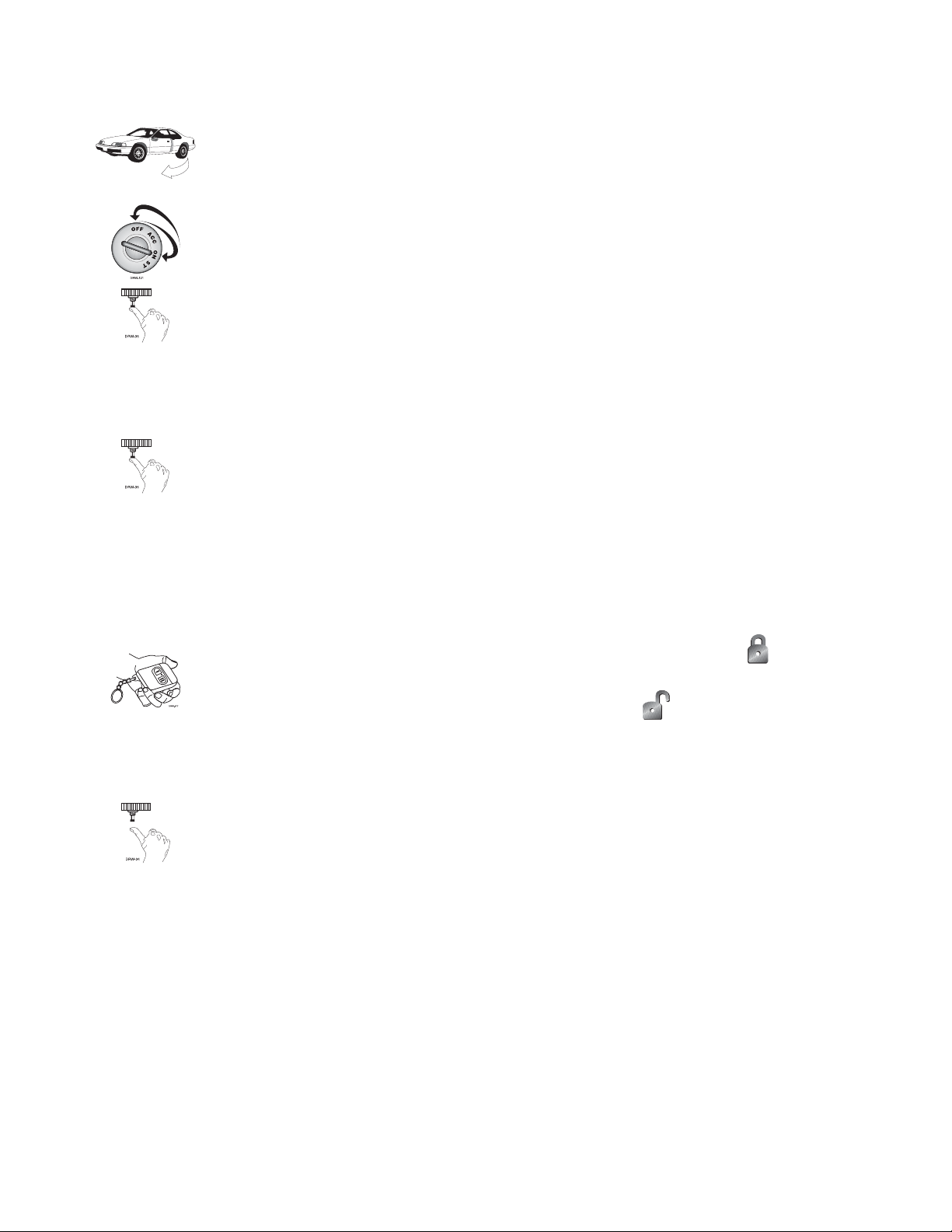
TToo eenntteerr oorr eexxiitt vvaalleett mmooddee wwiitthh tthhee vvaalleett//pprrooggrraamm sswwiittcchh::
1. Turn the ignition key on and then off.
2. At anytime during the next 10 seconds, press and release the Valet® switch. Now the
Status LED will light constantly if you have entered Valet® Mode, and go out if you have
exited Valet® Mode.
TToo eenntteerr oorr eexxiitt vvaalleett mmooddee wwiitthh tthhee ttr
raannssmmiitttteerr::
To enter or exit Valet® Mode with a transmitter:
1. Open any door.
2. Press on the transmitter.
3. Press .
4. Press again. You have now entered or exited Valet Mode (verify by checking your status LED).
Page 36

3366
ttaabbllee ooff zzoonneess
When using the Diagnostic functions, use the Table of Zones to see which input has triggered the system. It is
also helpful in deciding which input to use when connecting optional sensors and switches.
NNOOTTEE
: The Warn Away® response does not report on the LED.
lloonngg tteerrmm eevveenntt hhiissttoorryy
The system stores the last two full triggers in memory. These are not erasable. Each time the unit sees a full
trigger, the older of the two triggers in memory will be replaced by the new trigger. To access long term event
history:
1. With the ignition off, press and
HHOOLLDD
the Valet®/Program switch.
2. Turn on the ignition.
3. Release the Valet®/Program switch.
4. Press and release the Valet®/Program switch within 5 seconds. The LED will flash in groups
indicating the last two zones that triggered the unit for one minute or until the ignition
is turned off.
NNOOTTEE::
The Warn Away triggers are not stored to memory and will not be reported.
ZZOONNEE NNOO.. TTRRIIGGGGEERR TTYYPPEE IINNPPUUTT DDEESSCCRRIIPPTTIIOONN
1 Multiplexed Input BLUE (H1/6)
2 Multiplexed Shock Sensor Input Mux BLUE wire.
3 Door Trigger GREEN (H1/5) and VIOLET (H1/7).
4 Multiplexed Shock Sensor Mux GREEN wire
5 Ignition Yellow ribbon harness wire
Page 37

3377
ttrroouubblleesshhoooottiinngg
■
SShhoocckk sseennssoorr ddooeessnn''tt ttrriiggggeerr tthhee aallaarrmm::
Has the NPC™ system been triggered? If so, you will hear 5 chirps when disarming. To check this, turn the igni-
tion key on and off to clear the NPC™'s memory, and then retest the shock sensor. For a detailed description of
NPC™, see
Nuisance Prevention Circuitry
section of this guide.
■
DDoooorr iinnppuutt ddooeess nnoott iimmmmeeddiiaatteellyy ttrriiggggeerr ffuullll aallaarrmm.. IInnsstteeaadd,, cchhiirrppss aarree hheeaarrdd ffoorr tthhee ffiirrsstt 33 sseecco
onnddss::
That's how the progressive two-stage door input works! This is a feature of this system. This is an instant trigger,
remember, since even if the door is instantly closed again, the progression from chirps to constant siren will continue.
■
CClloossiinngg tthhee ddoooorr ttrriiggggeerrss tthhee ssyysstteemm,, bbuutt ooppeenniinngg tthhee ddoooorr ddooeess nnoott::
Have you correctly identified the type of door switch system? This happens often when the wrong door input
has been used. (See
Door Lock Harness Wire Connection Guide
section of this guide.)
■
SSyysstteemm wwiillll nnoott ppaassssiivveellyy aarrmm uunnttiill iitt iiss rreemmootteellyy aarrmmeedd aanndd tthheenn ddiissaarrmmeedd::
Are the door inputs connected? Is the H1/6 blue wire connected to the door trigger wire in the vehicle? Either
the H1/5 green or the H1/7 violet should be used instead. (See wiring diagrams.)
■
DDoooorr iinnppuutt ddooeess nnoot
t rreessppoonndd wwiitthh tthhee pprrooggrreessssiivvee ttrriiggggeerr,, bbuutt wwiitthh iimmmmeeddiiaattee ffuullll aallaarrmm::
Does the Status LED indicate that the trigger was caused by the shock sensor? (See
Diagnostics
section of this
guide.) The shock sensor, if set to extreme sensitivity, may be detecting the door unlatching before the door
switch sends its signal. Reducing the sensitivity can solve this problem.
■
TThhee VVaalleett®®//PPrrooggrraamm sswwiittcchh ddooeessnn''tt wwoorrkk..
Is it plugged into the correct socket? See
Plug-In LED and Valet®/Program Switch
section of this guide.
■
SSttaattuuss LLEEDD ddooeessnn''tt wwoorrkk..
You've probably guessed already, but here goes: Is it plugged in? (See
Plug-In LED and Valet®/Program Switch
section of this guide.) Is the LED plugged into the correct socket?
■
DDoooorr lloocckkss ooppeerraattee bbaacckkwwaarrddss..
This unit has easily-reversed lock/unlock outputs. Recheck wire connections to see if you have reversed these.
aallaarrmm ttrroouubblleesshhoooottiinngg
Page 38

3388
wwiirriinngg qquuiicckk rreeffeerreennccee gguuiiddee
YELLOW (+) ignition input
Empty
Valet/Program
button
LED
data port
LIGHT-GREEN/BLACK (-) factory alarm disarm
GRAY/BLACK No function
GREEN/WHITE (-) factory alarm rearm
VIOLET/BLACK (-) 200mA channel 4 output
GREEN (-) lock (+) unlock
WHITE/BLACK (-) 200mA channel 5 output
BLUE (+) unlock (-) lock
LIGHT BLUE (-) 2nd unlock output
+-
563/564
polarity
Jumper
light flash
RED 12V constant input
RED/WHITE (-) 200mA channel 2 validity output
BLACK (-) ground input
BROWN (+) siren output
BLUE (-) trunk trigger input
GREEN (-) door trigger input
VIOLET (+) door trigger input
WHITE/BLUE No function
WHITE (+/-) parking light output
BLACK/WHITE (-) 200mA domelight output
ProSecurity Programmer
ORANGE ground when armed output
Shock sensor port
Transceiver
Page 39

3399
Page 40

Get Started
Get Protected
Ungo Pro Security
661 W. Redondo Beach Blvd.
Gardena, Ca. 90247
800-GO-CLARION
© 2005 Directed Electronics, Inc. - All rights reserved NS660 02-05
 Loading...