

Page 1

Model 24921
Installation Guide
© 2010 Directed Electronics, Vista, CA
N24921 2010-08
Page 2

Bitwriter®, Code Hopping™, Doubleguard®, ESP™, FailSafe®, Ghost Switch™, Learn Routine™, Nite-Lite®, Nuisance
Prevention® Circuitry, Revenger®, Silent Mode™, Soft Chirp®,
Stinger®, Valet®, Vehicle Recovery System®, VRS®, and
Warn Away® are all Trademarks or Registered Trademarks of
Directed Electronics.
Page 3

Contents
Important information ...................................................................................................................... 4
Installation tools ............................................................................................................................. 4
Installation overview ........................................................................................................................ 5
Wiring schematic ............................................................................................................................ 6
Wiring connections ......................................................................................................................... 7
Main harness (H1), 9-pin connector ............................................................................................. 7
Heavy gauge relay harness, (H2) 6-pin connector ......................................................................... 7
Auxiliary harness (H3), 5-pin connector ....................................................................................... 7
Control button (valet switch), 2-pin connector ................................................................................ 7
Main harness (H1) connections ......................................................................................................... 8
Factory alarm disarm ................................................................................................................. 8
Ground wire ............................................................................................................................. 9
Parking light flash ...................................................................................................................... 9
Heavy gauge relay harness (H2) ..................................................................................................... 10
Testing for Ignition Wires .......................................................................................................... 10
Accessory and starter Wires ..................................................................................................... 11
Additional heavy gauge harness wire description ....................................................................... 13
Auxiliary harness (H3) ................................................................................................................... 14
Tachometer wire connections .................................................................................................... 14
Safety Shutdown Wires ............................................................................................................ 15
Mounting the antenna .................................................................................................................... 16
Installation points ......................................................................................................................... 17
Engine/voltage monitoring ...................................................................................................... 17
Virtual tach ............................................................................................................................. 17
Tach learning .......................................................................................................................... 17
Reset and deletion ......................................................................................................................... 18
Neutral safety switch interface ........................................................................................................ 18
Testing the neutral safety switch ................................................................................................. 18
Remote start shutdown diagnostics .................................................................................................. 19
Programming system features .......................................................................................................... 19
Feature menu ................................................................................................................................ 20
Remote control programming .......................................................................................................... 21
Troubleshooting: Remote start ......................................................................................................... 22
Warning! Safety first ..................................................................................................................... 26
Safety check ................................................................................................................................. 27
Page 4

Important information
Government Regulations and Safety information
Read the Government Regulations and Warning! Safety First sections of this manual
prior to operating this system.
Warning!
erty damage and may also result in the illegal use of the system beyond its intended
purpose.
Failure to heed this information can result in death, personal injury or prop-
Guide Translations
If you want a Spanish or French version of the Installation/Owners Guide, please download it from www.readyremote.com
and click on On-Line Tech Support.
Estimado Cliente:
Si buscas los guías de instalación/del usario, por favor de bajar lo del Soporte Técnico en-línea en el sitio www.readyremote.
com
Cher consommateur:
Si vous désirez une version française ou espagnole du guide d’utilisateur ou d’installation, veuillez s.v.p. le télécharger à
l’adresse suivante: www.readyremote.com en appuyant sur l’icône <<On-line Tech Support>>.
Installation tools
• Digital Multi-Meter
• Drill
• 1/4 Drill Bit (for hood pin switch)
• Screwdrivers (Phillips and Flathead)
• Wire Stripper
• Solder Iron
• Electrical Tape
• Pliers
• Crimping Tool
• Safety Glasses
Note: The installation tools listed above may be optional. The required tools will vary
4
© 2010 Directed Electronics. All rights reserved.
Page 5

Installation overview
Be sure to read this section thoroughly and view the Do-It-Yourself Installation DVD video that came with your
system in its entirety before starting the installation. Pay special attention to all warnings to prevent personal
injury or damage to your vehicle.
Register at www.readyremote.com to gain access to our vehicle database where you can get specific installation information for your vehicle. If needed, additional hardware to support the features you want, is identified.
Ensure you have or can borrow items listed in the Tools required section of this guide.
If you find that this installation is too difficult to perform, please visit the Professional Installer Network section of the www.readyremote.com web site or visit www.proinstall.com to contact one of our 7,000 autho-
rized retailers to have the product professionally installed.
• Verify that the transmission is set to park and that the parking brake is set before beginning installation.
• On vehicles with air bags or supplemental restraint systems (SRS) you may notice a bright yellow tube
with small wires in it, marked SRS, underneath the steering column near the key cylinder. DO NOT tam-
per or unplug these for any reason to prevent costly damages to your vehicle or personal injury. Tamper-
ing may cause unintended deployment of airbags.
• This system is intended for automatic, fuel-injected vehicles only. Installation in any other vehicle is con-
trary to its intended use.
Warning!
injury, or both.
Failure to properly install this product may result in costly damages, personal
© 2010 Directed Electronics. All rights reserved.
5
Page 6
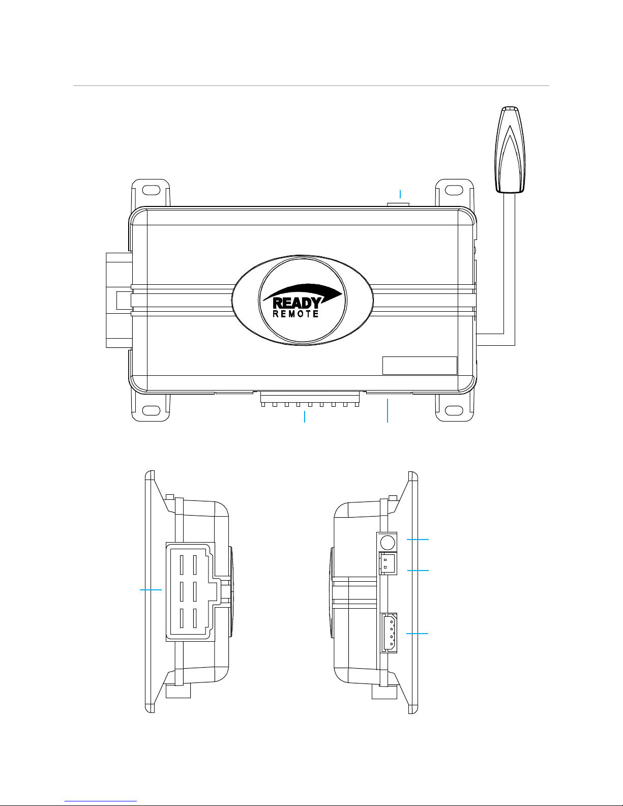
Wiring schematic
Primary Harness
Control Button
(Valet Switch)
Door Lock/unlock
Harness
Side View
Auxiliary Harness
Antenna
LED
Top View
Side View
Antenna
Parking Light
Jumper
Antenna
Parking Light
Jumper
Top View
H2
Heavy
Gauge
Relay
Side View
H1
H3
LED (Programming
indicator)
Control Button
(Valet Switch)
Antenna
6
© 2010 Directed Electronics. All rights reserved.
Page 7
Wiring connections
Main harness (H1), 9-pin connector
LIGHT GREEN BLACK (-) 200mA FACTORY ALARM DISARM
H1/1
GREEN/WHITE (-) 200mA FACTORY ALARM REARM
H1/2
EMPTY NOT USED
H1/3
WHITE/BLUE (-) ACTIVATION INPUT
H1/4
EMPTY NOT USED
H1/5
EMPTY NOT USED
H1/6
EMPTY NOT USED
H1/7
BLACK GROUND
H1/8
WHITE (+/-) LIGHT FLASH OUTPUT
H1/9
Heavy gauge relay harness, (H2) 6-pin connector
PINK OUTPUT TO PRIMARY IGNITION CIRCUIT, 30A (+)
H2/1
PURPLE OUTPUT TO STARTER CIRCUIT, 30A (+)
H2/2
ORANGE OUTPUT TO ACCESSORY CIRCUIT, 30A (+)
H2/3
RED (+) 30A HIGH CURRENT 12V INPUT
H2/4
PINK/WHITE PROGRAMMABLE OUTPUT, 2ND IGNITION/ACCESSORY CIRCUIT 30A
H2/5
RED (+) 30A HIGH CURRENT 12V INPUT
H2/6
Auxiliary harness (H3), 5-pin connector
H3/1 BLACK/WHITE (-) NEUTRAL SAFETY SWITCH INPUT
H3/2 VIOLET/WHITE TACHOMETER INPUT WIRE
H3/3 BROWN (+) BRAKE SHUTDOWN INPUT WIRE
H3/4 GRAY (-) HOOD PIN SWITCH SHUTDOWN WIRE
H3/5 BLUE/WHITE (-) 200 mA 2ND STATUS/REAR DEFOGGER
Control button (valet switch), 2-pin connector
BLACK INPUT
1
GREY OUTPUT
2
© 2010 Directed Electronics. All rights reserved.
7
Page 8
Main harness (H1) connections
Factory alarm disarm
LIGHT GREEN BLACK (-) 200mA FACTORY ALARM DISARM
H1/1
Since many newer vehicles come equipped with a factory alarm, it is necessary to disarm it when unlocking
the doors or during remote start. Do not mistake a factory alarm with an immobilizer system. They each
require different disarm operations.
Locate the factory alarm disarm wire following instructions available on www.readyremote.com. Once
the suspect wire is located, place the multi-meter's red lead to a (+)12 volt constant source and secure it.
Put the multi-meter in the DC position. Then probe the suspect wire with the black lead of your meter. While
probing the wire, place the key in the driver's door cylinder. Turn it to the unlock position and hold it when
testing for the disarm wire. The multimeter should read 12V and will go back to 0V when the key is released.
When the correct wire has been found, solder the LIGHT GREEN/BLACK wire of the 9-pin harness to the
wire that you determined to be the factory alarm disarm wire. After this wire has been connected, wrap the
connection with electrical tape.
Some vehicles use a (+) trigger factory alarm system. Use the website resource to determine if your vehicle has
a (+) trigger. If your vehicle has such a system, call 1-800-477-1382 for live technical assistance,
as special wiring and an additional relay is required.
GREEN/WHITE (-) 200mA FACTORY ALARM REARM
H1/2
This wire sends a negative pulse every time the remote start shuts down or the doors are locked. This can be
used to pulse the arm wire of the vehicle’s factory anti-theft device.
EMPTY NOT USED
H1/3
WHITE/BLUE (-) ACTIVATION INPUT
H1/4
This wire allows you to activate the Ready Remote via a pre-existing alarm or keyless-entry system. Two (-)
pulses to this wire will activate remote start.
EMPTY NOT USED
H1/5
EMPTY NOT USED
H1/6
EMPTY NOT USED
H1/7
8
© 2010 Directed Electronics. All rights reserved.
Page 9

Ground wire
BLACK GROUND
H1/8
The BLACK wire connects to the pin next to the light flash jumper fuse. First strip back a ¾-inch section of the
insulation off the BLACK wire and crimp a ring terminal (not provided) to that wire. Locate a clean, paint-free
metal surface in the drivers kick panel (DO NOT GROUND ON DASH). Using a self-tapping screw, drill the
screw with the ring terminal to the kick panel. Once screwed down, pull on the wire to ensure a good connection.
Parking light flash
WHITE (+/-) LIGHT FLASH OUTPUT
H1/9
There are several different types of parking light circuits. The following description is for a standard positivetriggered parking light circuit only. If the web vehicle information suggests a (-) parking light circuit, the fuse
jumper (on the side of the module) must be moved to the opposite position.
Using the web information on the vehicle, locate the suspected wire. Connect the black multimeter lead to
ground in the kick panel. Probe the suspected wire with the red lead of your meter. With the switch in the off
position the multimeter should read 0 volts. While watching the multimeter, turn your headlight switch to the
parking light position. The multimeter should read 12 volts.
While testing the suspected wire, run the dash dimmer light control up and down. The voltage should NOT
vary. If the voltage does vary, then this is the wrong wire. Continue probing to find the correct wire.
Once you have identified the correct wire, solder the small ORANGE wire of the 6-pin harness to it and wrap
the connection with electrical tape. If your light circuit tests the opposite position, you most likely have a (-)
parking light circuit.
© 2010 Directed Electronics. All rights reserved.
9
Page 10

Heavy gauge relay harness (H2)
Testing for Ignition Wires
PINK OUTPUT TO PRIMARY IGNITION CIRCUIT, 30A (+)
H2/1
With the multimeter lead still connected in the kick panel, locate the suspected ignition wire. It will test differently than constant 12 volts. Place the red lead of the multimeter on the suspected wire. With the key in the
off position the multimeter will read 0. Turn the key to the on position and the multimeter will read 12 volts.
Now, watching your multimeter, turn the key to the crank position. If the 12 volts stays on, then you have found
your ignition wire. If the wire tests correctly, solder the PINK heavy gauge wire to it and wrap the connection
with electrical tape.
If the vehicle requires more than one ignition as per the information found at www.readyremote.com,
follow the same test procedure and solder the PINK/WHITE (H2/5) heavy gauge wire to it then wrap the
connection with electrical tape. If your vehicle has only one ignition wire, secure the PINK/WHITE wire and
dress it out of the way.
If your vehicle requires more than two ignitions, an additional relay (not provided) is required. Refer to the
diagram below.
PINK/WHITE (+) OUTPUT
TO 2nd IGNITION
+12 VDC CONSTANT (FUSED 20A)
TO 2nd IGNITION
+12 VDC CONSTANT (FUSED 20A)
86
86
87
85
87A
30
TO 2
87
85
87A
30
TO 3rd IGNITION
2nd IGNITION RELAY
(NOT PROVIDED)
GROUND
nd
IGNITION
3rd IGNITION RELAY
(NOT PROVIDED)
GROUND
10
© 2010 Directed Electronics. All rights reserved.
Page 11

Accessory and starter Wires
PURPLE OUTPUT TO STARTER CIRCUIT, 30A (+)
H2/2
ORANGE OUTPUT TO ACCESSORY CIRCUIT, 30A (+)
H2/3
The starter and accessory wires will be located in the same harness as the ignition and constant power.
To find the accessory wire, leave the multimeter’s black lead connected to ground. Take the red lead and
probe the wire suspected to be the accessory wire. With the key off, your multimeter should read 0 volts.
Turn the key to the on position The multimeter should read 12 volts. Now turn the key to the crank position.
If you have the correct accessory wire, the multimeter will read 0 volts while the starter is cranking, and 12
volts once the key returns to the on position. If the wire tests correctly, strip some insulation off and solder the
ORANGE heavy gauge wire and wrap it with electrical tape.
If your vehicle requires more than one accessory and the PINK/WHITE wire is not being used for 2nd ignition,
you can program the PINK/WHITE to be a 2nd accessory output. This setting may be found in the Feature
Menu, Feature # 6.
If the PINK/WHITE wire is being used for Ignition 2, an additional relay (not provided) is required for a 2nd
accessory. Refer to the diagram below.
ORANGE (+) 30A OUTPUT TO
ACCESSORY CIRCUIT
+12 VDC CONSTANT (FUSED 20A)
86
30
+12 VDC CONSTANT (FUSED 20A)
86
30
1st ACCESSORY RELAY
(NOT PROVIDED)
87
GROUND
85
87A
TO ACCESSORY
2nd ACCESSORY RELAY
(NOT PROVIDED)
87
GROUND
85
87A
TO 2nd ACCESSORY
© 2010 Directed Electronics. All rights reserved.
11
Page 12

Now that the accessories have been located, find the suspected starter wire according to the web information. Leave the black lead of your tester on ground and place the red lead of your multimeter on this wire.
The multimeter should read 0 volts in all key positions except the crank position. In the crank position your
multimeter should read 12 volts, and will go to 0 volts when the starter disengages.
Many Nissan and Toyota vehicles have two starter wires. A relay and/or resistor (not provided) is required
to hook up the additional starter wire. Refer to the diagram below.
+12 VDC CONSTANT (FUSED 20A)
STARTER RELAY
(NOT PROVIDED)
PURPLE (+) OUTPUT
TO STARTER
TO STARTER
+12 VDC CONSTANT (FUSED 20A)
87
86
87A
30
87
86
87A
30
GROUND
85
TO STARTER
2nd STARTER RELAY
(NOT PROVIDED)
GROUND
85
TO 2nd STARTER
Important! Always check www.readyremote.com
for information on your vehicle for warnings regarding
the starter wire and engine lights. Some vehicles will trip
a check engine light if the starter wire is cut.
Once you locate the starter wire, cut the wire in half (check the web information before cutting) and try to
start the vehicle. If the vehicle does not start, the correct wire has been identified. Reconnect both ends of
the starter wire while soldering the thick PURPLE H2/2 wire of the heavy gauge wires to it and wrap the connection with electrical tape.
Ignition Output wire
The PINK wire should be the ONLY ignition output to an existing aftermarket alarm system. This wire will
prevent the host system from sensing that the ignition is on during remote start operation.
12
© 2010 Directed Electronics. All rights reserved.
Page 13

Additional heavy gauge harness wire description
RED (+) 30A HIGH CURRENT 12V INPUT
H2/4
RED (+) 30A HIGH CURRENT 12V INPUT
H2/6
Constant Power and Ignition Wires
Almost all your power and ignition wires can be found behind the key cylinder under the lower driver's side
dash panel. Using the appropriate hand tools, remove the lower dash panel taking care not to break any
parts. If the panel does not come off easily, check for any additional screws you may have missed.
Once the lower dash panel has been removed, locate the ignition harness at the back of the key cylinder. This
is usually a group of heavy gauge wires (approximate 14ga.).
Place the black lead of the LED tester to a clean metal surface in the kick panel area and secure it. Probe one
of the thicker gauge wires. The ignition wire colors of your specific vehicle can be obtained at
www.readyremote.com.
Important: More problems are attributed to poor ground connections
than any other cause. Take extra care to ensure the ground is a
clean metal-to-metal contact and secure.
Testing for Constant Power Wires
Warning! Before making any connection to constant battery power,
make sure that the two 30 amp fuses are removed from the fuse holders on the two pink 12 VOLT wires. Failure to do so may cause fire or
shorting of sensitive electrical components.
With the key in the off position, test the suspect wire. The constant power wire will read 12V on the multimeter.
Once the constant power wire has been identified, solder the two heavy gauge 12 VOLT wires RED from the
control module to it and wrap the connection with electrical tape.
If the vehicle has two constant power wire, use both of them. Connect one of the heavy gauge RED wires to
one of constant power wires and the other heavy gauge RED wire to the other vehicle constant power wire.
PINK/WHITE PROGRAMMABLE OUTPUT, 2nd IGNITION/ACCESSORY CIRCUIT 30A
H2/5
This wire may be used if vehicle requires more than one ignition. If the vehicle does not require more than
one ignition it can be reprogrammed to act as an accessory wire. This is helpful if there is 1 ignition and 2
accessory wires in the vehicle. See Feature Menu 2 and Programming System Features for instructions on
changing the function of this wire.
© 2010 Directed Electronics. All rights reserved.
13
Page 14

Auxiliary harness (H3)
H3/1 BLACK/WHITE (-) NEUTRAL SAFETY SWITCH INPUT
In most applications the neutral safety wire should be attached to a chassis ground. This does not apply to
vehicles that crank the starter while the transmission is in gear. If your vehicle cranks the engine while the
transmission is in gear you MUST call technical support at: 1-800-477-1382.
H3/2 VIOLET/WHITE TACHOMETER INPUT WIRE
Tachometer wire connections
Caution! In the following procedure DO NOT use a test light. Use of this
type of tester can cause grounding of sensitive electrical components, resulting in damage, including damage to the power train control module.
A digital multi-meter is required to test for this wire.
Do not wear loose clothing that could get entangled in rotating engine
components. Ensure that your hands and arms are well clear of these
rotating components when working in the engine compartment. Lastly,
ensure that all wires and tools are clear of falling into or entanglement
with these rotating components.
Identify the suspected tach wire according to the web information. Next, place the black lead of a MULTIMETER on the negative battery post and secure it. Put the multi-meter in the AC position and connect the probe
to the suspect wire with the red lead of the multi-meter. Then start the vehicle with the key. With the engine
at idle the multi-meter should read from .50 volts to 6 volts, and should fluctuate when you rev the engine.
Have a second person press the gas pedal to increase the RPMs and watch the meter display. When the RPMs
increase the voltage should rise slightly (not all tachometer outputs will rise when engine RPM increases).
Once the correct tachometer wire has been identified, turn the vehicle off.
Run the VIOLET/WHITE wire from the 5-pin harness through the firewall into the engine compartment alongside the hood pin wire. Use the same procedure as with the hood pin wire and pull the wire through the grommet, taking extra care to keep it away from any moving parts or anything that will generate extreme heat.
Once the wire is run into the engine compartment, strip a small portion of insulation off the tachometer wire
in the vehicle and solder the green tachometer input wire to it. Then wrap the connection with electrical tape.
Important: If using a tach signal, the tach signal must be learned before
using the remote start. (See Tach learning section)
14
© 2010 Directed Electronics. All rights reserved.
Page 15

Safety Shutdown Wires
H3/3 BROWN (+) BRAKE SHUTDOWN INPUT WIRE
H3/4 GRAY (-) HOOD PIN SWITCH SHUTDOWN WIRE
With all ignition wires properly connected, find the appropriate safety shutdown wires. These are the brake
wire and hood pin wires.
Warning! These wires are meant to protect the vehicle and anyone near
the vehicle. They MUST be connected to prevent damage to the vehicle and
possible bodily injury.
First locate the factory brake wire using your multimeter. Find the switch at the top of the metal arm coming
off the brake pedal. Use your vehicle specific wiring information to determine the color of this wire. With
the black lead of your multimeter still in the kick panel, probe the suspected wire with the red lead of your
multimeter.
With the brake pedal at reset, the multimeter should read 0 volts. While watching the multimeter, depress the
brake pedal. The multimeter should read 12 volts. Once you have located the correct brake wire, solder the
small BROWN (H3/3) wire in the 5-pin harness to it and wrap the connection with electrical tape.
Warning! Do not use the vehicle until you confirm the operation of
the brake shutdown.
Installing the hood pin switch requires drilling a hole in a metal lip under the hood. Choose a location that
will allow the pin switch to be completely depressed when the hood is closed. The pin switch has a spade
connector on the bottom for the wire connection.
Always wear eye protection when drilling.
Crimp your spade connector to the hood pin wire, and run the wire into the vehicle's passenger compartment
through a factory rubber grommet , at the same time run the Tachometer Input wire [and Horn output wire
from the Optional Harness through the fire wall. To connect them use the following steps.
Using a sharp, pointed object, poke a hole into the grommet (being careful not to damage any existing wires
in the grommet) and attach the wire to the object with electrical tape. Pull the wire through the grommet,
taking extra care to keep the wire away from any moving parts or anything that will generate extreme heat.
An alternative to this method would be to find a spot on the firewall with sufficient clearance on both sides
and drill an access hole through the firewall. Take note of what is directly on the other side of where you are
drilling as to not puncture brake cylinders, computers, etc. Once the wire is run into the vehicle and secured
from any moving parts, solder the wire to the GRAY wire H3/4 of the 5-pin harness and wrap the connection
with electrical tape.
Warning! The GRAY wire must be connected. do not use the vehicle
until you confirm the operation of the hood pin shutdown. Improper
operation could result in serious injury or death.
H3/5 BLUE/WHITE (-) 200 mA 2ND STATUS/REAR DEFOGGER
This wire may be used to activate a bypass module in default mode, or it can activate the defogger circuit
when Feature Menu 2, option 8, is changed to an option setting.
© 2010 Directed Electronics. All rights reserved.
15
Page 16

Mounting the antenna
The best location for the receiver/antenna is centered high on either the front or rear windshield. For optimal
range, the antenna should be mounted vertically. It can be mounted horizontally in relation to the windshield
or under the dashboard away from metal, but range will be diminished. Window tint or dot matrix (small
black dots at top of windshield) can also affect range, so this should be a consideration when determining
the mounting location.
After determining the best mounting location, follow these steps:
1. Clean the mounting area with a quality glass cleaner or alcohol to remove any dirt or residue.
2. Plug the receiver/antenna cable into the receiver/antenna.
3. Mount the receiver/antenna using the supplied double-sided tape.
4. Route the receiver/antenna cable to the control module and plug it into the four-pin antenna connec
tor.
Important: To achieve the best possible range, DO NOT leave the antenna cable bundled under the dash. Always extend the cable full length
during installation, regardless of the antenna mounting location.
16
© 2010 Directed Electronics. All rights reserved.
Page 17

Installation points
Important: The LED mentioned in the installation section references the LED (programming indicator) on the
Control Module, not on the remote control, unless otherwise stated.
Engine/voltage monitoring
During remote start, the system needs to know if the engine is running. The module does this by monitoring
the voltage of the vehicle's electrical system (or the tachometer: see next section).
Vehicle electrical systems usually rest at about 12.6 volts when the engine is not running. This system is programmed to detect the rise in battery voltage that occurs when the charging circuit activates after starting,
and keep the engine running if the rise is adequate. It will make up to three start attempts before discontinuing
due to an inadequate voltage rise.
Some vehicles have alternators that do not activate immediately or do not increase voltage sufficiently after
starting. This system will compensate by delaying the time before reading the battery voltage on the second
and third start attempts. This delay will allow most alternators to activate so the remote start continues to run.
The voltage read times are:
First attempt: 10 seconds
Second attempt: 20 seconds
Third attempt: 50 seconds
After the third start attempt, if the voltage increase is still not adequate to keep the engine running, the Tachometer input option should be used to monitor the engine.
Virtual tach
Use of Virtual Tach does not require the Tach wire to be connected.
To program Virtual Tach:
1. After the install is complete, remote start the engine. The programming operation may require 3 cranks of
the starter before the engine starts and runs. Do not turn off the remote start if this happens, it is a normal
programming operation.
2. Once the engine begins running, let it run for at least 30 seconds.
3. Using the Remote, send the Remote start command to turn remote start off. Virtual Tach is programmed.
Virtual Tach is not recommended for diesel vehicles. Virtual Tach handles disengaging the starter motor during remote starting – it does not address over-rev. For over-rev protection capability, the tach wire must be
connected.
Important: After successfully learning Virtual Tach, a small minority of vehicle starters may over crank or under crank during remote start. Virtual Tach fine tune can be
adjusted, see Feature Menus and Programming System Features.
Tach learning
Note: Tach learning requires H3/2 (Violet/White) wire to be connected to Tach. If using Virtual Tach, this
procedure is not required and should not be used.
To learn the tach signal:
1. Start the vehicle with the key.
2. Within 5 seconds, press and hold the Control (Valet switch) button.
3. After 3 seconds the LED lights constant when the tach signal is learned.
4. Release the Control button.
© 2010 Directed Electronics. All rights reserved.
17
Page 18

Reset and deletion
If a feature/Virtual Tach needs to be reset or the remote controls need to be deleted, use the following procedure.
1. Turn the ignition to the ON position (The heavy gauge pink wire must be connected).
2. Within 10 seconds, press and release the Control button (Valet switch): 2 times if you want to delete re-
motes, 3 times to reset features or 4 times to reset Virtual Tach. These features are described next.
Delete remotes: This feature erases all remote controls from the system memory. This is useful in cases
when a remote is lost or stolen. You can program new remote controls to the system, see Remote
Control Programming section of this guide.
Note: This does not reset the programmed features of the system or reset the Virtual Tach setting.
Reset Features: This resets all the system features to the factory default settings.
Note: This feature does not delete the remotes from the system or reset the Virtual Tach setting
Virtual Tach Reset: Deletes all previously learned values for Virtual Tach, and on the next remote start
sequence the unit begins virtual tach initialization.
3. Once you have selected the function step, press the Control button once more and hold it. The LED on
the control module flashes to confirm the selected functional step. Do not release the Control button.
4. While holding the Control button, press the single button on the remote control. The LED on the control
module flashes to confirm that the feature has been successfully reset. Once the feature is reset, the Control
button can be released.
Neutral safety switch interface
Some vehicles do not have an electrical neutral safety switch, but instead have a mechanical neutral safety
switch that interrupts the starter wire when the vehicle is in any drive gear. The remote start must be interfaced
before the neutral safety switch , to provide protection from starting in gear. However, some vehicles combine
the column shift and the neutral safety switch into one mechanical part, and in this case you will not be able
to interface the remote start before the neutral safety switch.
Important: You must complete the remote start system installation before doing the following test. Ensure that the remote start system is functioning normally. This includes connecting to the brake as a shut-down.
Testing the neutral safety switch
1. Make sure there is adequate clearance to the front and rear of the vehicle because it may move slightly.
2. Make sure the hood is closed and there are no remote start shut-downs active.
3. Set the emergency brake.
4. Turn the key to the “run” position, this releases the shifter.
5. Place the car in drive (D).
6. Place your foot directly over the brake pedal, but do not depress it. Be ready to step on the brake if the
starter engages.
7. Activate the remote start system.
8. If the starter engages, immediately depress the brake to shut the remote start system down. If the
starter does not engage, no additional safety system is required.
If the starter engages and the vehicle is a General Motors product or Dodge Dakota pickup, refer to
www.
directechs.com
prevents the starter from engaging.
for Document 1008 under the Resource tab, for an alternative shut-down method which
If the vehicle is not a General Motors product or a Dodge Dakota pickup, please call Directed Electronics
Technical Support at 1-800-477-1382 for an alternative shut-down method.
18
© 2010 Directed Electronics. All rights reserved.
Page 19

Remote start shutdown diagnostics
If the remote start activates but fails to stay running, the remote start module has the ability to inform you of
what may have caused the remote start failure. Before performing shutdown diagnostics it is important that
you let the remote start shut off on its own i.e. let it attempt to start 3 times then shut down, if this is not done
the unit will report the shutdown you used to shut off the remote start.
Note: Shutdown diagnostics does not report if the vehicles factory immobilizer is causing the problem.
To perform shutdown diagnostics:
1. With the ignition Off, press and hold the Control (valet switch) button.
2. Turn the ignition On and then back Off while holding the Control button.
3. Release the Control button.
4. Press and release the Control button. The LED on the control module flashes to report the last shutdown
for one minute or until the ignition is turned on, as shown in the following table:
LED Flashes Shutdown Mode
1 flash Runtime expired
2 flashes Over-rev shutdown
3 flashes Low or no RPM, low battery (voltage and virtual tach modes)
4 flashes Transmitter shutdown
5 flashes (-) Hood shutdown (H3/4 GRAY)
6 flashes Brake (+) Shutdown (H3/3 BROWN)
7 flashes Neutral safety shutdown (H3/1BLACK/WHITE)
8 flashes Wait-to-start timed out
Programming system features
The System Features Learn Routine dictates how the unit operates. It is possible to access and change most of
the feature settings using the Control module (Valet Switch) button.
1. Turn the ignition on, then off.
2. Select a Feature. Press and release the Control button the number of times corresponding to the
feature you wish to change. Then press and hold one more time to select the feature. The LED flashes
to indicate which feature # is selected.
3. Program the Feature. While holding the Control button, you can program the feature using the remote
control.
Pressing the button on the remote control selects the options in ascending order. The LED flashes indicatiing
which option is selected.
Once a feature is programmed:
• Other features can be programmed within the same menu
• The learn routine can be exited if programming is complete
To access another feature in the same menu:
• Press and release the Control button the number of times necessary to advance from the feature you just pro-
grammed to the next one you want to program next, then press the Control button once more and hold it.
The learn routine exits if any of the following occurs:
• The ignition is turned On
• There is no activity for 30 seconds
• The Control button is pressed too many times
© 2010 Directed Electronics. All rights reserved.
19
Page 20

Feature menu
Default settings are in bold type.
Feature # Feature Opt. 1 Opt. 2 Opt. 3 Opt.4 Opt. 5+
1 Engine checking
2 Remote Start Engine
Runtime
3 Park light output Pulsed
4 Cranking time
5 Activation pulse count
6 2nd Ignition / Acc
behavior
7 Accessory output
8 Status behavior
9 Diesel wait-to-start
timer
10 Virtual tach fine tune
11 Factory alarm disarm
pulse
Virtual
tach
12 min
0.6 sec
1 pulse
Ignition
Off during
wait-tostart
Normal
Off
0 (as
learned)
Single
voltage Off tachometer
24 min 60 min
Constant
0.8 sec. 1.0 sec. 1.2 sec. 1.4, 1.6, 1.8, 2.0,
.
2 pulses 3 pulses
Accessory
On during
wait-to-start
Latch rear
defogger
Timed 15 sec Timed 30
100ms to 1 sec ( in 100 ms increments)
Double
Pulse rear
defogger
sec.
Timed 45
sec.
4.0 sec
1. Engine checking
1. VirtualTach: battery voltage drop/rise during cranking determines when the starter output is
released. During runtime, constant voltage level is monitored to determine if the engine is running.
2. Voltage: starter output during cranking is a programmed duration (Set in Cranking Time). During
runtime, constant voltage level is monitored to determine if the engine is running.
3. Off: starter output during cranking is a programmed duration (Set in Cranking Time). The remote
start keeps the ignition/accessories active for the programmed runtime whether the engine is running
or not.
4. Tachometer: tach input signal during cranking and runtime determines when the starter output is
released and if the engine is running.
2. Engine Runtime
• 12/24/60 minutes: sets engine runtime during normal remote start operations.
3. Park light output
1. Pulsed: the lights will pulse on/off during remote start.
2. Constant: the lights will turn on solid during remote start.
4. Cranking time
• 0.6/0.8/1.0/1.2/1.4/1.6/1.8/2.0/4.0 seconds: determines the starter output duration during
cranking for the ‘Voltage’ and the ‘Off’ Engine Checking Mode options.
5. Activation pulse count
• 1/ 2/ 3 pulses: sets the number of remote control commands received or Activation Input required
to activate and de-activate remote start.
6. 2nd Ignition behavior
1. Ignition 2: the relay will emulate the Ignition 1 output during remote start.
2. Accessory 2: the relay will emulate the Accessory 1 output during remote start.
20
© 2010 Directed Electronics. All rights reserved.
Page 21

7. Accessory output
1. Off: the Accessory outputs will be OFF during diesel start delay.
2. On: the Accessory outputs will be ON during diesel start delay.
8. 2nd Status behavior
1. Normal : the output will activate before the ignition outputs turn on, and de-activate after they turn
off during remote start.
2. Latch rear defogger: the output activates 10 seconds after start. It turns off after 10 minutes or upon
remote start off.
3. Pulse rear defogger: the output activates (for 800mS) 10 seconds after start.
9. Diesel start delay
1. Off
2. On: Opt 2-4, Timed 15/30/45 seconds: delays the starter output.
10. Virtual Tach fine tune
• 0 as learned: 100ms to 1 sec (in 100 ms increments)
11. Factory Alarm Disarm pulses
1. Single: Factory Alarm Disarm wire pulses once per operation
2. Double: Factory Alarm Disarm wire pulses twice per operation
Remote control programming
1. Turn key to the ON position
2. Within 5 seconds, press and release Control (Valet Switch) button one time.
3. Within 5 seconds, press and hold the Control button. The LED (on the control module) flashes one time
to confirm entry into remote programming.
4. Press the button on the remote control.
5. The LED flashes to confirm the remote has been programmed.
6. Release the Control button, and turn the key to the Off position.
7. The LED turns on solid for a while to confirm that remote programming has been exited.
The programming routine exits if any of the following occurs:
• The ignition is turned off
• There is no activity for 30 seconds
• The Control button is pressed too many times
© 2010 Directed Electronics. All rights reserved.
21
Page 22

Troubleshooting: Remote start
The remote will not activate the remote start
1. Does the neutral safety input have a ground? if the wire is not grounded the remote start will not
activate.
2. Have you performed the remote start shutdown diagnostics? Sometimes an active shutdown input will
report in the diagnostics.
3. Is the remote programmed to the system?
4. Can the remote start be activated manually by applying a ground pulse to the H1/4 White/Blue
wire? Grounding the white/blue the correct amount of times activates remote start without using the
remote.
5. Check the harnesses and their connections. Make sure that the harnesses are completely plugged into
the remote start module. Make sure there are good connections to the vehicle wiring.
6. Check voltage and fuses on the system.
The remote start will activate, but the starter never engages.
1. Check for voltage on the purple starter wire two seconds after the remote start becomes active. If
there is voltage present, skip to Step 5. If there is no voltage present, advance to Step 2.
2. Check the 30A fuses.
3. If the wait-to-start timer is turned on, the starter will not crank.
4. Is the tach wire connected? If so disconnect it and remote start the vehicle to see if the purple wire
sends out voltage. If you get voltage, go to an alternate tach source. The tach wire you are currently
on has a voltage spike when the ignition is powered up, which can cause the remote start to not send
out the crank voltage.
5. Is the vehicle a Chrysler or GM with a multiplexed starter wire? The vehicle will not crank if the resistance is incorrect on the multiplexed accessory/starter wire.
6. Is the vehicle a GM? If so the PINK/WHITE 2nd accessory needs to be powered up on some of the
vehicles for the vehicle to crank.
7. Does the vehicle have an immobilizer? Some immobilizer systems will not allow the vehicle to crank
if active.
8. Check connections. The heavy gauge remote start input wires on the heavy gauge 6-pin connector
should have a solid connection.
The vehicle starts, but immediately dies.
1. Does the vehicle have an immobilizer? The vehicle’s immobilizer can cut the fuel and/or spark during
unauthorized starting attempts.
2. Is the remote start programmed for virtual tach or voltage sense? If so, the crank time may not be set
high enough. Voltage sense will not work on some vehicles.
3. Is the remote start in tach mode? If so has the tach been programmed to the system?
4. Check diagnostics. Sometimes a shutdown will become active during cranking or just after cranking.
The vehicle starts, but the starter keeps running.
1. Is the system programmed for engine checking off or virtual tach voltage sense? When programmed
for either of these features, the engine cranks for the pre programmed crank time regardless of how
long it takes for the vehicle to actually start. Adjust to a lower cranking time.
2. Was the Tach Learn successful? The LED must light solid and bright to indicate a successful learn.
3. Make sure that there is a tach signal at the purple/white tach input wire of the remote start. If there
is not a tach signal, recheck the connection to the vehicle’s tach wire and make sure the wire is not
broken or shorted to ground leading to the remote start.
4. Is an ignition or accessory output wire connected to the starter wire of the vehicle? Verify the color
of the starter wire in the vehicle and confirm that an ignition or an accessory output is not connected
to that wire.
The vehicle starts, but will only run for 10 seconds
1. Is the remote start programmed for voltage sense? If this does not work, a tach wire should be
used.
2. Check shutdown diagnostics.
22
© 2010 Directed Electronics. All rights reserved.
Page 23

The climate control system does not work while the unit is operating the vehicle.
1. Either the wrong accessory wire is being energized or more than one igni tion or accessory wire must
be energized in order to operate the climate control system.
2. If the vehicle has an electronic climate control system some will reset when the key is turned off and
then back on, unfortunately this is a function of the vehicle and cannot be bypassed.
© 2010 Directed Electronics. All rights reserved.
23
Page 24

Owner's Guide
Sirius -Read y, SAT Radi o Rea dy or selec t OEM headu nits with o ption al Hon da Bu s Com patibl e Tra nslato r
Headuni t bus cable SiriusC onnect Cable
HON-SC1
Honda Bus
Compatible
Translator
Sirius -Read y, SAT Radi o Rea dy or selec t OEM headu nits with o ption al Hon da Bu s Com patibl e Tra nslato r
Headuni t bus cable SiriusC onnect Cable
HON-SC1
Honda Bus
Compatible
Translator
System Maintenance
The system requires no specific maintenance beyond battery replacement for the remote control. Your remote is powered by
a coin cell battery (3V CR2032) that lasts approximately one year under normal use. When the battery begins to weaken
operating range is reduced.
Battery Replacement
Locate the small slot on the side of the remote control. Insert a small slotted screwdriver or equivalent tool into slot and pry the
case apart. Replace battery while verifying the correct polarity and then snap case together.
Using the system
Car Finder
Car finder allows you to locate your vehicle, by having the system flash the parking lights. Before the vehicle is remotely started
via the remote control,
lights flash 5 times slowly.
Remote Start
This feature allows you to remotely start and run your vehicle for a pro gram ma ble period of time. This makes it possible to warm
up the engine, and adjust the interior tem per a ture of the ve hi cle with the climate control system. If interior heating or cooling
is desired, the climate controls must be preset, and the fan blower must be set to the desired level prior to remote starting the
vehicle.
press
and
hold
the remote control button for 3 seconds to activate the car finder function. The parking
Warning!
(1) Never remote start your vehicle when
the keys are in the ignition, except when performing
Valet Take-Over, and (2) Never start the vehicle if it
is not in PARK or NEUTRAL
To remote start the vehicle:
•
Press
the button on the remote control once (default)*.
• The parking lights flash to confirm that the vehicle is attempting to start. In gasoline vehicles the engine starts 4 seconds
after the parking lights flash, in diesel vehicles the engine starts after the Wait-To-Start timer has expired (default is Off)*.
• Once the vehicle has started, it will run for 12 minutes (default)*, or until a shutdown input is trig gered.
*
Defaults: Remote Start Activation Pulse Count (button presses), Wait-To-Start timer and Engine Runtime can be changed, see
corresponding features in Feature Menu and Programming System Features.
Warning!
It is unsafe to operate a vehicle’s motor in
a garage or other closed off area. Breathing the exhaust from the vehicle is hazardous to your health.
Never activate the remote start in an enclosed space.
When you are ready to drive the vehicle:
1.
Insert
the ignition key and
po sition.
2.
Press
the brake pedal. The remote start system shuts down and the engine continues to run because the ignition has been
turned on.
Note:
If the brake pedal is pressed before the key is in the On position, the engine will shut down.
turn
it to the On (not the START)
24
© 2010 Directed Electronics. All rights reserved.
Page 25

While the vehicle is running during remote start operation, the system monitors the ve hi cle and automatically shuts down the
engine if it receives any of the following shut-down inputs:
• The brake pedal is pressed.
• The hood is opened.
• The shutdown toggle switch is put into the Off position.
• The pre-programmed run time has elapsed.
• Remote control button is pressed and held for 3 seconds.
Valet Take-Over
The Valet Take-Over feature allows the vehicle to remain running after the key has been removed from the ignition. This feature
is useful for occasions when you wish to exit and lock the vehicle for short periods of time, but would like to leave the engine
running and the climate controls on.
To perform Valet Take-Over:
1. Before turning off the engine, press and release the button on the remote control for 1 second.
2. Turn the ignition key to the Off position. The engine will stay running until the pre- pro gram med time has elapsed or a shutdown input is received. (See the previous Remote Start section for a complete list of shut-down inputs.)
Important: This feature will not work if the brake pedal is being pressed.
Government Regulations
This device complies with Part 15 of FCC rules. Operation is subject to the following two conditions: (1) This device may not cause harmful
interference, and (2) This device must accept any interference received, including interference that may cause undesirable operation.
This equipment has been tested and found to comply with the limits for a class B digital device, pursuant to Part 15 of the FCC Rules. These
limits are designed to provide reasonable protection against harmful interference in a residential installation. This equipment generates and
can radiate radio frequency energy and, if not installed and used in accordance with the instruction manual, may cause harmful interference to
radio communications. However, there is no guarantee that interference will not occur in a particular installation. If this equipment does cause
harmful interference to radio or television, which can be determined by turning the equipment OFF and ON, the user is encouraged to try to
correct the interference by one or more of the following measures:
• Reorient or relocate the receiving antenna.
• Increase the separation between the equipment and receiver.
• Connect the equipment into an outlet on a circuit different from that to which the receiver is connected.
• Consult the dealer or an experienced radio / TV technician for help.
This device complies with the Industry Canada Radio Standards Specification RSS 210. Its use is authorized only on a no-interference, noprotection basis; in other words, this device must not be used if it is determined that it causes harmful interference to services authorized by IC.
In addition, the user of this device must accept any radio interference that may be received, even if this interference could affect the operation
of the device.
Warning:
Changes or modifications not expressly approved by the party responsible for compliance could void the user’s authority to operate this device.
© 2010 Directed Electronics. All rights reserved.
25
Page 26

Warning! Safety first
The following safety warnings must be observed at all times:
• Due to the complexity of this system, installation of this product must be done properly according to instructions with safety always considered.
• Failure to properly installed this system and its safety features may result in personal injurt, property damage or both.
When properly installed, this system can start the vehicle via a command signal from the remote control.
• Therefore, never operate the system in an enclosed areas or a partially enclosed area without ventilation
(such as a garage).
• When parking in an enclosed or partially enclosed area or when having the vehicle serviced, the remote
start system must be disabled using the installed toggle switch. It is the user’s sole responsibility to properly handle and keep out of reach from children all remote controls to assure that the system does not
unintentionally remote start the vehicle.
USER MUST INSTALL A CARBON MONOXIDE DETECTOR IN OR ABOUT THE LIVING AREA ADJACENT TO THE
VEHICLE. ALL DOORS LEADING FROM ADJACENT LIVING AREAS TO THE ENCLOSED OR PARTIALLY ENCLOSED
VEHICLE STORAGE AREA MUST REMAIN CLOSED AT ALL TIMES.
Use of this product in a manner contrary to its intended mode of operation may result in property damage,
personal injury, or death. Except when performing the Safety Check outlined in this installation guide,
(1) Never remotely start the vehicle with the vehicle in gear, and (2) Never remotely start the vehicle with the
keys in the ignition. The user must have the neutral safety feature of the vehicle periodically checked, wherein
the vehicle must not remotely start while the car is in gear. This testing should be performed by an authorized
Directed dealer. If the vehicle starts in gear, cease remote start operation immediately and consult with an
authorized Directed dealer to fix the problem.
After the remote start module has been installed, perfrom the Safety Check outlined in this guide. If the vehicle
starts when performing the Neutral Safety Shutdown Circuit test, the remote start unit has not been properly
installed. The remote start module must be removed or properly reinstalled so that the vehicle does not start
in gear.
OPERATION OF THE REMOTE START MODULE IF THE VEHICLE STARTS IN GEAR IS CONTRARY TO ITS INTENDED MODE OF OPERATION. OPERATING THE REMOTE START SYSTEM UNDER THESE CONDITIONS
MAY RESULT IN PROPERTY DAMAGE OR PERSONAL INJURY. YOU MUST IMMEDIATELY CEASE THE USE
OF THE UNIT AND SEEK THE ASSISTANCE OF AN AUTHORIZED DRIECTED DEALER TO REPAIR OR DISCONNECT THE INSTALLED REMOTE START MODULE. DIRECTED WILL NOT BE HELD RESPONSIBLE OR PAY
FOR INSTALLATION OR REINSTALLATION COSTS.
CAUTION! This product is designed for fuel-injected, automatic transmission vehicles only. Installing it in a
standard transmission vehicle is dangerous and is contrary to its intended use.
26
© 2010 Directed Electronics. All rights reserved.
Page 27

Safety check
Before vehicle reassembly, the remote system must be checked to ensure safe and trouble-free operation. The
following test procedure must be used to verify proper installation and operation of the system. The
installation must be completed before testing, including connection to the brake switch and hood switch.
1. Test the BRAKE shutdown circuit: With the vehicle in Park (P), activate the remote start system. Once the
engine is running, press the brake pedal. The engine should shut down immediately. If the engine continues to run, check the brake circuit connection.
2. Test the HOOD PIN shutdown circuit: With the vehicle in Park (P), open the hood. Activate the remote start
system. The vehicle should not start. If the starter engages, check your hood pin and connections. Note: If
programmed for Diesel Mode, the system will turn on the ignition, but the starter should not engage with
the hood open.
3. Test the NEUTRAL SAFETY shutdown circuit:
Important: Make sure there is adequate clearance to the front and rear
of the vehicle before attempting this test.
a. Make sure the hood is closed and no other shutdown circuits are active.
b. Set the emergency brake.
Note: Failure to do so could result in personal injury, property damage or both.
c. Turn the ignition key to the run position but do not start the engine.
d. Put the vehicle in Drive (D).
e. Put your foot over the brake pedal but do not press down on it. Be ready to step on the brake to
shutdown the remote start system.
f. Activate the remote start system.
• If the starter engages, immediately step on the brake to shut down the system. If it does engage, recheck
the neutral safety input connection. The vehicle may use a mechanical neutral safety switch.
• If the starter does not engage, the test is complete. Once the system passes all three tests, the vehicle can
be re-assembled. Do not the use the remote start system or finalize the installation if it fails any of the
safety check tests.
© 2010 Directed Electronics. All rights reserved.
27
Page 28

The company behind this system is Directed Electronics
Since its inception, Directed Electronics has had one purpose, to pro-
vide consumers with the finest vehicle security and car stereo products
and accessories available. The recipient of nearly 100 patents and
Innovation Awards in the field of advanced electronic technology.
DIRECTED is ISO 9001
Quality Directed Electronics products are sold and serviced
throughout North America and around the world.
Call (800) 274-0200 for more information about our products and services.
Directed Electronics is committed to delivering world class quality
products and services that excite and delight our customers.
© 2010 Directed Electronics - All rights reserved
Directed Electronics
Vista, CA 92081
www.directed.com
N24921 2010-08
 Loading...