

Page 1

Warranty
LIMITED TWO YEAR CONSUMER WARRANTY
Directed Electronics, Inc. promises to the original purchaser, to replace this product should it
prove to be defective in workmanship or material under normal use, for a period of two y ears from
the date of purchase by the dealer as indicated by the date code marking of the product
PROVIDED the product was installed by an authorized Directed dealer. During this two year
period, there will be no charge for this replacement PROVIDED the unit is returned to Directed,
shipping pre-paid. If the unit is installed by anyone other than an authorized Directed dealer, the
warranty period will be 1 year from date of purchase by the dealer as indicated by the date code
marking of the product. During this 1 year period, there will be no charge for this replacement
PROVIDED the unit is returned to Directed, shipping pre-paid. This warranty is non-transferable
and does not apply to any unit that has been modified or used in a manner contrary to its
intended purpose, and does not cover damage to the unit caused by installation or removal of the
unit. This warranty is void if the product has been damaged by accident or unreasonable use,
neglect, improper service or other causes not arising out of defects in materials or construction.
ALL WARRANTIES INCLUDING BUT NOT LIMITED TO EXPRESS WARRANTY, IMPLIED
WARRANTY,WARRANTY OF MERCHANTABILITY, FITNESS FOR PARTICULAR PURPOSE,
AND WARRANTY OF NON-INFRINGEMENT OF INTELLECTUAL PROPERTY ARE
EXPRESSLY EXCLUDED TO THE MAXIMUM EXTENT ALLOWED BY LAW,AND DIRECTED
NEITHER ASSUMES NOR AUTHORIZES ANY PERSON TO ASSUME FOR IT ANY LIABILITY
IN CONNECTION WITH THE SALE OF THE PRODUCT. DIRECTED HAS ABSOLUTELY NO
LIABILITY FOR ANY AND ALL ACTS OF THIRD PARTIES INCLUDING ITS AUTHORIZED
DEALERS OR INSTALLERS. Unit must be returned to Directed, postage pre-paid, with:
consumer's name, telephone number, and address, authorized dealer's name and address, and
product description. IN ORDER FOR THIS WARRANTY TO BE VALID, YOUR UNIT MUST BE
SHIPPED WITH PROOF OF INSTALLATION BY AN AUTHORIZED DIRECTED DEALER.ALL
UNITS RECEIVED BY DIRECTED FOR WARRANTY REPAIR WITHOUT PROOF OF
DIRECTED DEALER INSTALLATION WILL BE COVERED BY THE LIMITED 1 YEAR PARTS
AND LABOR WARRANTY. Note:This warranty does not cover labor costs for the removal and
reinstallation of the unit.
BY PURCHASING THIS PRODUCT,THE CONSUMER AGREES AND CONSENTS THAT ALL
DISPUTES BETWEEN THE CONSUMER AND DIRECTED SHALL BE RESOLVED IN
ACCORDANCE WITH CALIFORNIA LAWS IN SAN DIEGO COUNTY,CALIFORNIA.
© 2003 Directed Electronics, Inc. All rights reserved. G41820 04-03
Page 2
for choosing
PrecisionPower
audio equipment. At
PrecisionPower
we proudly design and
engineer the world’s finest audio products. Our award winning products utilize innovative
design and technology to consistently deliver
Absolutely State of the Art™
performance,
sound quality, reliability, and value.This
PrecisionPower
product reflects our commitment
to offer you unparalleled versatility and quality for years of dependable service and
listening enjoyment.
Do not attempt to service
PrecisionPower
products yourself. Performing exploratory
surgery on your audio equipment yourself will void the warranty. Many parts of your
PrecisionPower
gear are custom built to our specifications.Our factory parts are not made
available to anyone else nor are they for sale. Our goal is to make sure that your
PrecisionPower
product will always sound as good as the day it was purchased. Contact
your authorized
PrecisionPower
dealer about obtaining any warranty service through
PrecisionPower
.(See Warranty inside back cover.)
Caution! The extended use of a high powered audio system may result in hearing loss or
damage. While
PrecisionPower
systems are capable of "Concert Level" volumes with
incredible accuracy, they are also designed for you to enjoy at more reasonable levels all
of the sonic subtleties created by musicians.Please observe all local sound ordinances.
1
Page 3

2/3-Way Active Crossover w/ x10 Frequency Multiplier Switch
High Level Input
Remote Sub Level Control
0-180 Degree Subwoofer Phase Switch
Active Bandpass Switch
Butterworth Filters with 12dB/octave Slopes
Detented Frequency Selection Controls
Gold-plated RCA Input and Output connectors
PowerLock Power, Ground and Remote connector
PWM Power Supply
QBASS Bass Boost
Signal-to-Noise Ratio > 102dB
Total Harmonic Distortion (1KHz, 1VRMS) < 0.01%
Crossover Slopes 12 dB/octave Butterworth
Crossover Frequencies
Front High-pass 50Hz to 8kHz
Rear High-pass or BandPass 50Hz to 8kHz
Subwoofer 5Hz to 800Hz
Remote Sub Level 0-10 dB boost, variable
QBASS Bass Boost 40Hz, 0-12 dB variable
High Level Input Voltage 2-7.5VRMS
Low Level Input Voltage 4 VRMS
Maximum Output (10 K Load) 4 VRMS
Supply V oltage 9-15 VDC
Dimensions (WxLxH) 6-3/16” x 6-7/8” x 1-1/4”
Replacement Fuse 1 amp
2
Page 4

X3 frequency controls are detented. Each “click” counted from the 50Hz mark
corresponds to a specific frequency. Refer to this char t and page 6 for set-up instructions.
DETENTS POSITION FREQUENCY
1 7 o’clock 50 Hz
2 54Hz
3 58Hz
4 62Hz
5 66Hz
6 70Hz
7 74Hz
8 9 0’clock 80Hz
9 92Hz
10 105Hz
11 117Hz
12 129Hz
13 140Hz
14 12 o’clock 152 Hz
15 174Hz
16 200Hz
17 217Hz
18 231Hz
19 249Hz
20 1 o’clock 267 Hz
21 292Hz
22 320Hz
23 360Hz
24 424Hz
25 480Hz
26 2 o’clock 512 Hz
27 568Hz
28 607Hz
29 637Hz
30 663Hz
31 671Hz
32 3 o’clock 680 Hz
33 688Hz
34 698Hz
35 710Hz
36 725Hz
37 738Hz
38 750Hz
39 765Hz
40 790Hz
41 5 o’clock 800 Hz
3
Page 5
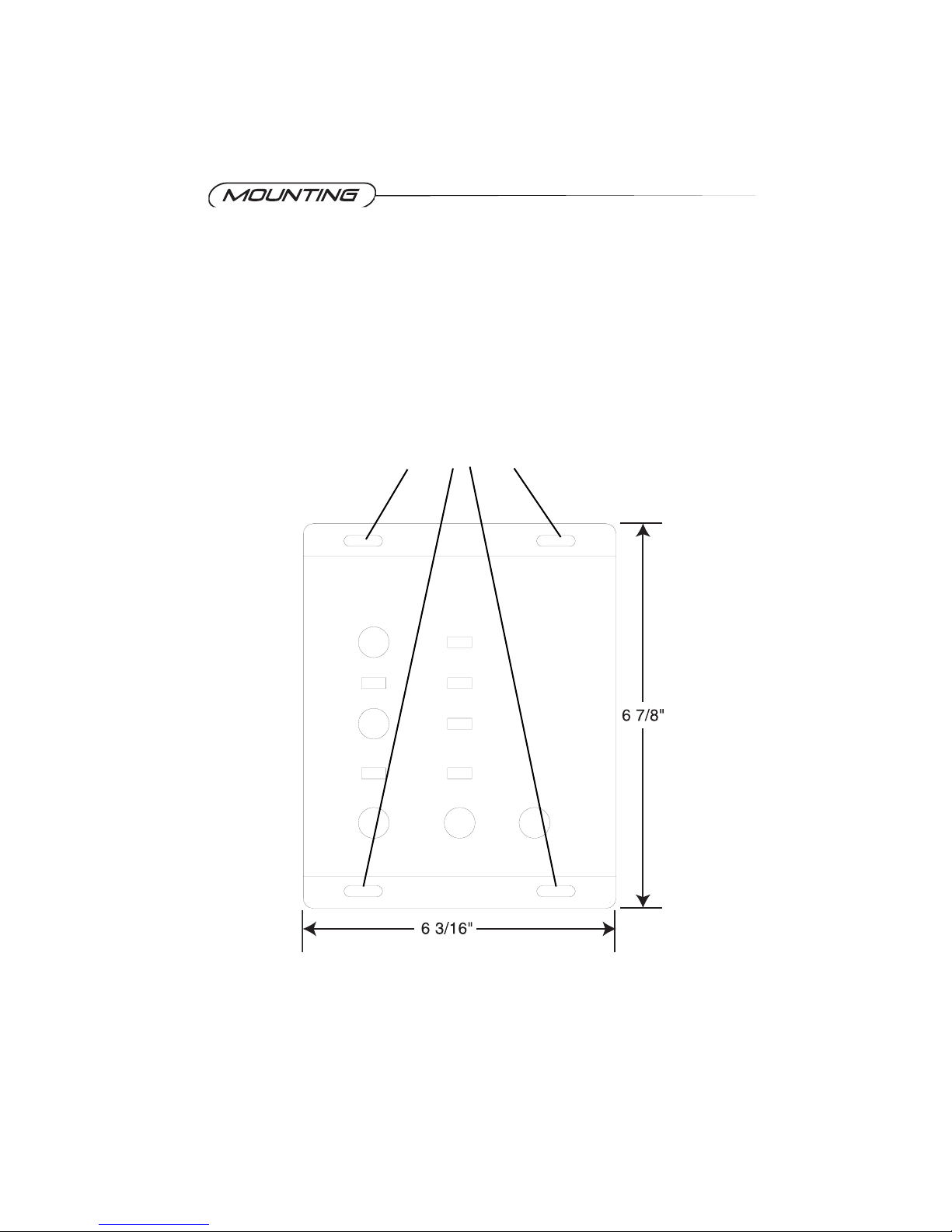
To prevent damage to the X3 while driving, mount it in a secure place. Choosing the
appropriate location will depend upon your vehicle and the complexity of your system
design. Typical mounting locations for your new X3 include the trunk or passenger
compartment (floor or under seat). Never mount the component in a location that would
subject it to immersion or exposure to water.
Once a location has been chosen, securely mount the X3 with four mounting screws.
Be Careful! Inspect the area underneath to be sure you are not drilling into wires, etc. that
could be damaged by the drill bit or screws.
4
Locations for mounting screws.
Page 6

Before beginning the installation disconnect the negative (-) terminal of the battery
prior to working on the positive (+) terminal to prevent a short to ground.This is
important, unless you want to spend the rest of your life with a nickname like
"Sparky," or "Smokey." Reconnect the negative ter minal only after all connections
have been made.
If your radio features a code type security system, be sure you know the code
before disconnecting the battery!
Don’t forget to reconnect the vehicle’s ground cable to the negative post of the
battery after all system power and ground connections have been completed.
5
Page 7

The next step is to connect the P o wer, Ground, and Remote wires to your X3.The po w er
wire should run from the mounting location through the vehicle to the battery or power
distribution block.install a fuseholder at the power end of this cable within 18 inches of the
power source.Avoid sharp corners, creases, and sharp body parts.When passing through
any metal wall (i.e.firewall etc.), a grommet must be used to prevent the wire from chafing
and shorting to ground.
The ground wire should be of the same gauge as the power wire.As a rule of thumb, use
as short a length of wire as possible.
Find a location near the X3 that is
metal (the floor pan is normally a good
location) and clean an area about the a
half inch in diameter to bare metal.Drill a
pilot hole in the middle of this area.
Be Careful! Inspect the area underneath
to be sure you are not drilling into wires,
brake or fuel lines, etc. Terminate the
wire with a ring connector and attach it to
the bare metal using a #8 sheet metal
screw and washer (not supplied). We
suggest crimping and/or soldering this
connection. After the connection is
complete, coat the area with silicone or
some similar material to prevent rust
from developing.
Connect the remote wire to the amp
remote wire of the head unit, or to the power antenna wire if the head unit does not have
a separate amp remote wire.This wire supplies a 12 volt signal to the X3 when the main
system is activated.
Once you have routed the po wer, ground, and remote wires through the vehicle, it is time
to connect the wires to the X3. Be sure that you have not reconnected the ground cable to
the negative post of the battery.
Cut off excess wire and, using wire strippers, strip the power, ground and remote cables
about 1/8 inch. Locate the power, ground, and remote Powerlock connector (supplied). On
the top of the connector are three slotted screws. With a small flat-bladed screwdriver,
loosen the screws before attempting to insert the cables. After you have inserted the
stripped end of each cable into the connector, secure it b y tightening the associated scre w.
Check that each connection is tight.If the wires are secure, the connector may be plugged
into the X3.
6
Page 8

7
1
73
5
2
4
6
8 10
9
11
12
Page 9

1. Power LED: Red light indicates power on.
2. Front Channel High-pass Frequency Control: This detented knob controls the
frequency of the front High-pass output from 50-8kHz
3. Multiplier: This switch multiplies the Front Channel High-pass Frequency Control from
either 50-800Hz (x 1) to 500-8kHz(x10). Switch to the left to multiply (x 1) and to the right
to multiply (x10).
4. Combine: This switch combines the Front and Rear inputs if only one RCA pair is
available for signal input. Switch to the left to combine inputs and to the right to use
separate inputs.
5. Bandpass: This switch allows the Front channel crossover to function as a 2 way
crossover. It will send a lowpass crossover frequency, at the same frequency that the front
channel is high-passed,so that you can run an active bandpass out of the Bandpass/Rear
High-pass RCA output.
6. Rear Channel High-pass Frequency Control: This detented knob controls the
frequency of the Rear High-pass output from 50-8kHz
7. Multiplier: This switch multiplies the Rear Channel High-pass Frequency Control from
either 50-800Hz (x 1) to 500-8kHz (x10). Switch to the left to multiply (x 1) and to the right
to multiply (x10).
8. Sub Input: This switch allows you to use the Rear Input to supply signal to the Subwoofer
Input section of the crossover if a dedicated RCA is not available to do so.
9. Sub Phase: This switch allows you to invert the subwoofer phase from 0 to 180Þ.
10. Sub Frequency Control: This detented knob controls the frequency of the Subwoofer
output from 50-800Hz.
11. Q BASS: This knob allows for a boost at 40Hz up to 12dB.
12. Sub Level: Allows you to control the subwoofer level up to 10dB.
8
Page 10

9
1
5
4
3
2
9
8
7
6
5
9
8
7
6
1
4
3
2
Page 11

1. High Level: Connect your speaker wire output from the headunit to these wires .Use this
method if your radio is not equipped with RCA outputs.
2. Front Input: Gold-plated RCA inputs.Plug in the RCA cables from the front channel of
your radio here.
3. Rear Input: Gold-plated RCA inputs. Plug in the RCA cables from the Rear channel of
your radio here.
4. Subwoofer Input: Gold-plated RCA inputs.Plug in the RCA cables from the Subwoofer
channel of your radio here, if equipped.If not, slide the Sub Input switch on the top of the
crossover to INT to use the signal from the rear input for the Sub Channel.
5. Sub LowPass:Gold-plated RCA outputs.Run the RCA cable to the Subwoofer amplifier
RCA input.
6. Remote Sub Level: Plug the remote sub level control into this jac k. Run the remote sub
level control to a position in the passenger area to allow control of the sub level.
7. Rear BandPass or High-Pass: Gold-plated RCA outputs. Run the RCA cable to the
Rear Speaker or midrange speaker amplifier RCA input.
8. Front High-Pass: Gold-plated RCA outputs.Run the RCA cable to the Front speaker or
tweeter amplifier RCA input.
9. Power: After connecting the Power, Ground and Remote wires to the Powerlock
connector, plug the connector in here.
10
Page 12

11
Page 13

12
Page 14

13
Page 15

14
Page 16

15
 Loading...