

Page 1

[
OWNER’S GUIDE
]
®
[
AUTO SECURITY SYSTEM
]
MODEL
MAXX3
Page 2

2
®2002 Directed Electronics
Table of Contents
Consumer Warranty . . . . . . . . . . . . . . 3
What Is Included. . . . . . . . . . . . . . 5
Important Information. . . . . . . . . . 5
Your Warranty. . . . . . . . . . . . . . . 6
Remote Controls . . . . . . . . . . . . . 6
System Maintenance . . . . . . . . . . 7
Remote Control Battery Replacement . 7
System Features . . . . . . . . . . . . . . 8
Stealth Coding Technology . . . . . . 8
Electronic Scan Prevention (ESP) . . 8
Interior Light Illumination . . . . . . 8
Passive Immobilisation. . . . . . . . . 9
Valet Switch. . . . . . . . . . . . . . . . 9
Keyless Entry in Valet Mode. . . . . . 9
Ultrasonic Sensors. . . . . . . . . . . . 9
Instant Remote Control Code Deletion 10
One-Step Remote Control
Code Learning . . . . . . . . . . . . . . 10
Alarm State Memory . . . . . . . . . . 10
Transmitter Functions . . . . . . . . . . 11
Accessory Outputs and
Button Assignments. . . . . . . . . . . 11
System Operation . . . . . . . . . . . . . 12
Active Arming . . . . . . . . . . . . . . 12
Passive Arming . . . . . . . . . . . . . . 12
Disarming the System
(if alarm is not sounding). . . . . . . 12
Disarming the System
(if alarm is sounding) . . . . . . . . . 13
Silent Arm/Disarm. . . . . . . . . . . . 13
Remote Panic . . . . . . . . . . . . . . . 13
Two-Stage Unlock Capability . . . . . 14
Sensor Bypass . . . . . . . . . . . . . . 14
Protected Valet Mode. . . . . . . . . . 15
How to Change Your PIN Code . . . . . 17
Diagnostics . . . . . . . . . . . . . . . . . 19
LED System Status Indicator . . . . . 19
Previous Intrusion Alert . . . . . . . . 19
Specific Zone Intrusion Identification. 19
Automatic Malfunction Override . . . 20
Interpreting Chirps and Flashes . . . 20
User-Programmable Features. . . . . . 21
Passive Arming . . . . . . . . . . . . . . 21
Passive Arming With Door Lock . . . 21
Auto-Rearm and Lock. . . . . . . . . . 22
Ignition-Controlled Door Lock/Unlock. 22
Long-Term Silent Arm/Disarm . . . . 23
Door Ajar Indication . . . . . . . . . . 23
Dual-Sensor Trigger Mode . . . . . . . 23
How to Set the User-Programmable
Features . . . . . . . . . . . . . . . . . . . 24
Programming Table
for System Features . . . . . . . . . . . 26
Programming Table
for Remote Controls. . . . . . . . . . . 27
Security & Convenience Expansions . 28
Glossary of Terms . . . . . . . . . . . . . 29
Quick Reference Guide. . . . . . . . . . 31
Health Check . . . . . . . . . . . . . . . . 33
Page 3

3
®2002 Directed Electronics
Consumer Warranty
For a period of five calendar years from the date of purchase of this vehicle security
device, Directed Electronics, Inc. promises to the ORIGINAL PURCHASER to repair or
replace (with a comparable reconditioned model), free of cost, the alarm control unit
if proved to be defective in workmanship or material under normal use, SO LONG AS
THE SYSTEM WAS SOLD, INSTALLED AND SERVICED BY AN AUTHORISED AVITAL
INSTALLER, AND REMAINS IN THE CAR IN WHICH THE SYSTEM WAS ORIGINALLY
INSTALLED. All other system parts are covered under the same warranty agreement for
a period of one year. If warranty service is necessary you must have a clear copy of
your sales receipt containing all of the information required.
This warranty contains the entire agreement relating to warranty and supersedes all
previous and contemporaneous representations or understandings, whether written or
oral. IN ANY EVENT, DEI IS NOT LIABLE FOR THE THEFT OF THE VEHICLE AND/OR ITS
CONTENTS.
This warranty is void if the product has been damaged by accident, unreasonable use,
neglect, improper service or other causes not arising out of defects in materials or
construction. This warranty is nontransferable and does not apply to any unit that
has been modified or used in a manner contrary to its intended purpose and does not
cover batteries. The unit in question must be returned to the manufacturer, postage
prepaid. This warranty d
oes not
cover labour costs for the removal, diagnosis, troubleshooting or reinstallation of the unit. For service on an out-of-warranty product a
flat rate fee by model is charged. Contact your authorised dealer to obtain the service charge for your unit.
These systems are a deterrent against possible theft. Directed Electronics, Inc. is not
offering a guarantee or insuring against the theft of the vehicle or its contents and
disclaims any liability for the theft of the vehicle and/or its contents. Directed
Electronics does not authorise any person to create for it any other obligation or liability in connection with this security system.
TO THE MAXIMUM EXTENT ALLOWED BY LAW, ANY AND ALL WARRANTIES ARE EXCLUDED BY THE MANUFACTURER AND EACH ENTITY PARTICIPATING IN THE STREAM OF COMMERCE THEREWITH. THIS EXCLUSION INCLUDES BUT IS NOT LIMITED TO THE EXCLUSION OF ANY AND ALL WARRANTY OF MERCHANTABILITY AND/OR ANY AND ALL WARRANTY OF FITNESS FOR A PARTICULAR PURPOSE AND/OR ANY AND ALL WARRANTY OF
NON-INFRINGEMENT OF PATENTS, IN THE UNITED STATES OF AMERICA AND/OR
ABROAD. NEITHER THE MANUFACTURER OR ANY ENTITIES CONNECTED THEREWITH
Page 4

4
®2002 Directed Electronics, Inc.
SHALL BE RESPONSIBLE OR LIABLE FOR ANY DAMAGES WHATSOEVER, INCLUDING BUT
NOT LIMITED TO ANY CONSEQUENTIAL DAMAGES, INCIDENTAL DAMAGES, TOWING,
REPAIR, REPLACEMENT, DAMAGES FOR LOSS OF TIME, LOSS OF EARNINGS, COMMERCIAL
LOSS, LOSS OF ECONOMIC OPPORTUNITY AND THE LIKE. NOTWITHSTANDING THE
ABOVE, MANUFACTURER DOES OFFER A LIMITED WARRANTY TO REPLACE OR REPAIR
THE CONTROL MODULE AS DESCRIBED ABOVE. This warranty gives you specific legal
rights. Your statutory rights are not affected.
Page 5

®2002 Directed Electronics, Inc.
5
What Is Included
■ One Avital Maxx3 Control Unit
■ One Valet Switch
■ One Status LED
■ One 4-Button/10-Channel Remote Control
■ One 2-Button/3-Channel Remote Control
■ Two Ultrasonic Sensors
■ One Battery Back-up Siren
■ One Certificate of Installation
■ Two Avital Window Decals
Important Information
Congratulations on your purchase of the Thatcham Evaluated Avital
Maxx3, our top of the range, vehicle security/convenience system.
To fully benefit from the capabilities of your system, we encourage
you to read the Owner’s Guide thoroughly. If you have any prob-
lems or questions, consult the dealer you purchased the system
from. To locate an authorised Avital dealer in your area, call our
UK office using the number noted in the back of this guide.
Page 6

®2002 Directed Electronics, Inc.
6
It is necessary to retain your proof of purchase, which reflects that
the product was installed by an authorised dealer. For full details
regarding your warranty coverage, please refer to the Consumer
Warranty section of this guide.
Included with your system: one AviGlo 4-button/10-channel
remote and one AviGlo 2-button/3-channel remote. Once exposed
to light, the AviGlo remote control buttons will glow, making them
visible in the dark.
The remote control is a miniature transmitter powered by a small
(+) 3 volt lithium battery. Obstructions, electrical or radio inter-
ference, weather conditions, window tint, or a discharged battery
can reduce range. Your transmitter is the key to your system and
can be used to arm and disarm your alarm, lock and unlock your
doors, open your boot, and control optional accessories such as a
remote engine starter*, window roll-up, and garage door opener.
Your system can accept up to four AviGlo remote controls.
Additional remote controls and remote control batteries can be
purchased from any authorised Avital dealer or by calling the UK
office (freephone number noted in the back of the guide).
* This accessory is not evaluated by Thatcham.
Remote Controls
Your Warranty
Page 7

®2002 Directed Electronics, Inc.
7
The Maxx3system requires no maintenance except for remote con-
trol battery replacement when they reach the end of their useful
life. When the battery weakens, operating range will be reduced
and the LED will dim. To replace your remote control battery use
the following procedure.
To replace the battery in your AviGlo remote control, follow the
instructions below.
1. Carefully pry apart the two halves of the remote control with
a small flat-bladed screwdriver. The bottom right-hand corner
of the remote casing has a small indent to allow the screw-
driver access.
2. The lithium battery is the round silver disc, about the size of
a five pence piece. Remove the old battery from the metal
clip. You should note that the (+) side of the battery should
face up and the (-) side should face the circuit board. Slide
the new replacement battery into the metal clip.
3. Re-align the two halves of the enclosure and snap together.
Remote Control Battery Replacement
System Maintenance
Page 8

®2002 Directed Electronics, Inc.
8
System Features
Stealth Coding technology offers the most advanced protection
available against code-grabbing devices which thieves may use to
record the digital code transmitted by your remote control. When
you leave the area, thieves can then play back the code to unlock
the doors and de-activate your system. Avital’s remote controls
with Stealth Coding randomly change the code every time you use
them, and your system will not respond if any code is re-transmit-
ted. This technology makes code-grabbing devices useless.
Your system includes Electronic Scan Prevention (ESP), which
blocks electronic scanner codes preventing unauthorised operation
of your system. A thief could use an electronic “scanner” to con-
tinuously scan through thousands of different transmitter codes in
an attempt to find one that will disarm your system. Your Maxx
3
system uses ESP technology to render this type of attack useless.
When the alarm system is remotely disarmed, the vehicle interior
light(s) will turn on for 30 seconds or until the ignition key is
turned on.
Interior Light Illumination
Electronic Scan Prevention (ESP)
Stealth Coding Technology
Page 9

®2002 Directed Electronics, Inc.
9
The built-in Dual Circuit Immobiliser will passively arm (indicated by
a slow LED flash), 30 seconds after the ignition is turned off. (This
feature is a Thatcham and EC requirement and, therefore, is not
user-programmable.) To disarm the Immobiliser when it has
Passively Immobilised, use the remote control to arm and then dis-
arm the system, or turn the ignition on and press the button.
The Valet switch is a small push-button switch that allows you to
control all of the system’s programmable features and enter your
override PIN code. (See User-Programmable Features section of this
guide.) This switch can only be controlled in conjunction with
your ignition key.
NOTE: Make sure the dealer has shown you where the Valet switch is
located. You will need to disarm the system with the Valet switch in the
event of a lost or stolen remote control.
While the system is in the Valet mode, you can still use your
remote control to lock and unlock the doors as well as activate any
optional accessories, such as boot release or remote engine
starter.
Your Maxx3security system incorporates two Ultrasonic sensors,
which are most commonly mounted at the top of the A-pillars fac-
Ultrasonic Sensors
Keyless Entry in Valet Mode
Valet Switch
Passive Immobilisation
Page 10

®2002 Directed Electronics
10
ing the rear of the vehicle. These sensors detect movement inside
the vehicle by sensing air disturbance. They should trigger the
alarm if a thief gained access to the interior of your vehicle.
In the event of a lost or stolen remote control, all remote controls
can be erased from the systems memory preventing unauthorised
system operation. (See the Programming Table for Remote Controls
section of this guide.)
Your system allows you to add new remote controls in one step. (See
the Programming Table for Remote Controls section of this guide.)
If your vehicle battery is disconnected and later reconnected, the
system will automatically return to its last state before power was
removed, whether it was armed, disarmed, or in Valet Mode. For
example, if a mechanic were to disconnect the battery while the
alarm was disarmed or in Valet Mode, the alarm will not trigger
when the battery is reconnected. If power is removed and then
restored while the alarm is armed, the systems battery back up
siren will instantly sound, the indicator lights will flash and the
Dual Circuit Immobiliser will still be enabled, preventing the vehi-
cle from being started.
Alarm State Memory
One-Step Remote Control Code Learning
Instant Remote Control Code Deletion
Page 11
®2002 Directed Electronics, Inc.
11
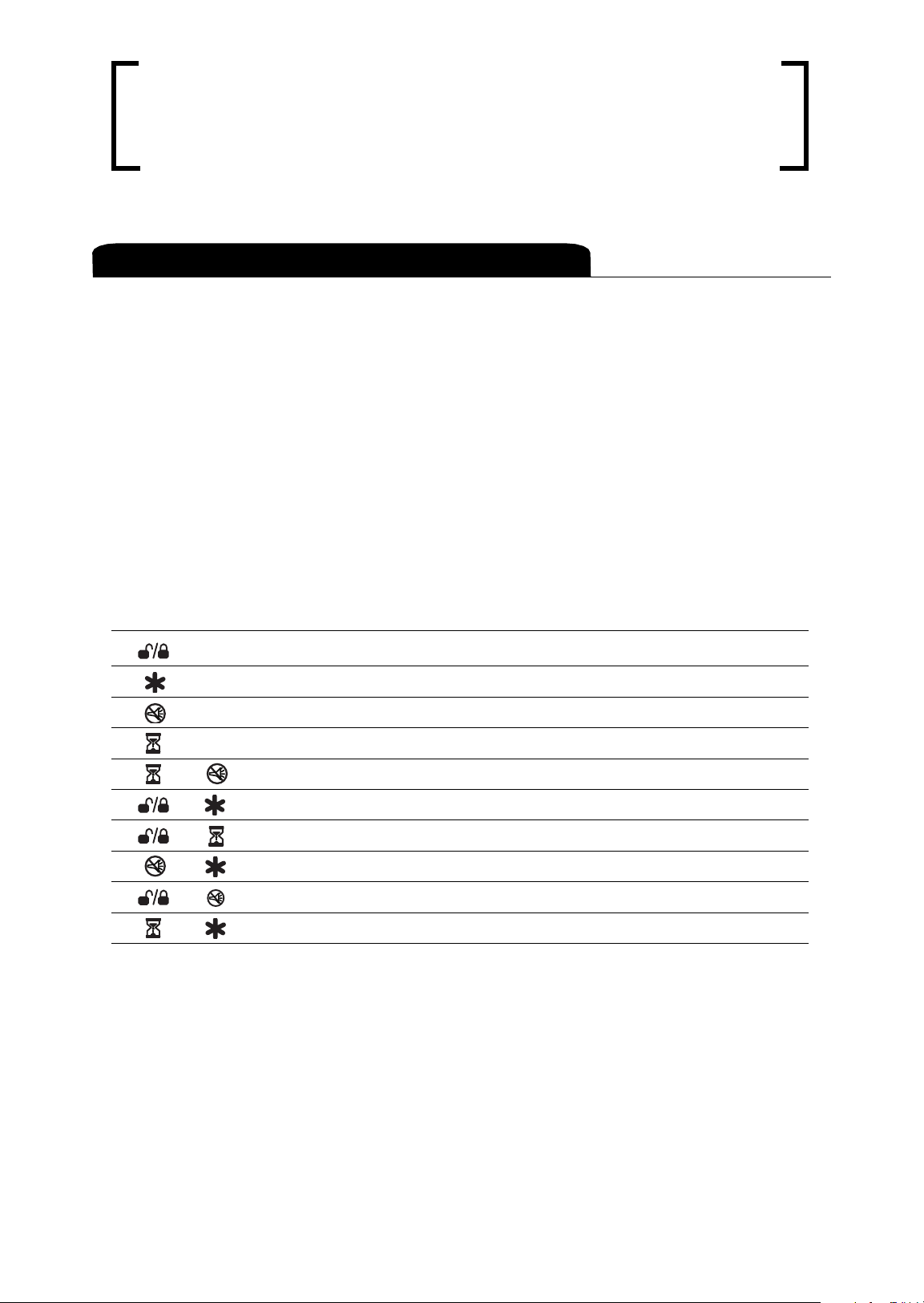
Transmitter Functions
These outputs allow you to add optional remote-controlled acces-
sories to your system such as a remote engine starter, boot
release, window roll-up, garage door opener, or fuel filler door
release. To activate your optional accessories press the correspon-
ding remote control buttons shown below. You can assign any
remote control function to any button sequence. (See
Programming Table for Remote Controls section of this guide.)
Button/Channel Assignment Feature
Button / Channel 1 Arm/Disarm/Panic/Two Stage Unlock
Button / Channel 2 Pulsed Accessory Output (Disarmed Only)
Button / Channel 3 * Silent Arm/Disarm
Button / Channel 4 * Timer Controlled Output
+ Buttons / Channel 5* Pulsed/Latched Accessory Output
+ Buttons / Channel 6 Sensor Bypass
+ Buttons / Channel 7 * Unassigned**
+ Buttons / Channel 8 * Unassigned**
+ Buttons / Channel 9 * Unassigned**
+ Buttons / Channel 10 * Unassigned**
* Only available with 4-button remote.
**Can be assigned to operate any of the first 6 channels on your Maxx
3
or to control other Avital systems and accessories on other vehicles.
Accessory Outputs and Button Assignments
Page 12

®2002 Directed Electronics, Inc.
12
System Operation
The alarm can be programmed for active or passive arming. Active
arming means the alarm is armed using the remote control. Passive
arming means the alarm will automatically arm itself. (See the
Programming Table for System Features section of this guide.)
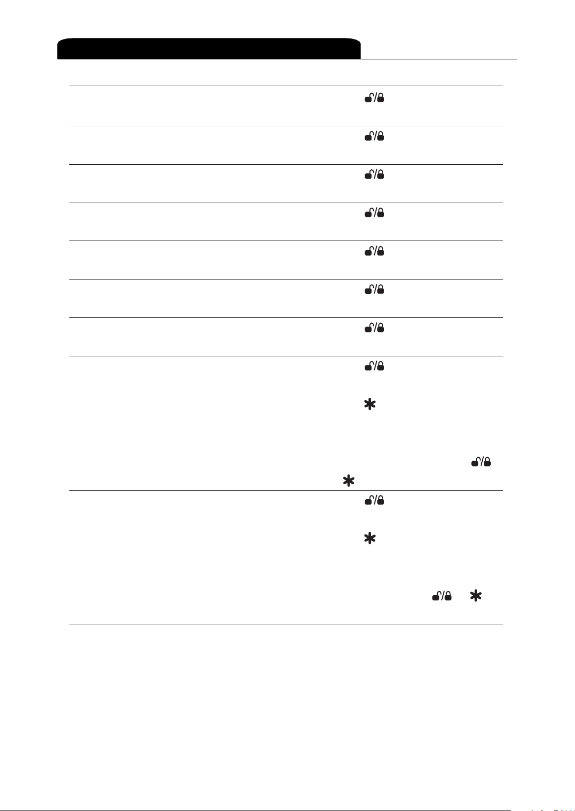
Press the button for one to two seconds. The following will occur:
■ The siren will chirp twice and the indicator lights will flash
twice. The doors will lock.* The LED will double flash, pause,
double flash, pause, etc., and the built in AutoImmobiliser
will disable two vital engine circuits.
* Requires connection to your vehicle’s existing central locking system.
The Maxx3 has three programmable options relating to passive
arming of the alarm. A full description of the operation and pro-
gramming options for the passive arming feature can be found on
page 21.
Press the button for one to two seconds. The following will occur:
■ The siren will chirp once and the indicator lights will flash
once. The doors will unlock.* The interior lights will turn on
Disarming the System (if alarm is not sounding)
Passive Arming
Active Arming*
Page 13

®2002 Directed Electronics, Inc.
13
(for 30 seconds or until the ignition is turned on). The immo-
bilised engine circuits will be re-enabled to allow you to start
your car. The LED will turn off.
* Requires connection to your vehicle’s existing central locking system.
Press the button for 1-2 seconds. This will silence the siren
only. It will not disarm the system or unlock* the doors. A second
press of the button for one to two seconds is required to fully
disarm the system.
* Requires connection to your vehicle's existing central locking system.
Pressing the button for one to two seconds will arm and dis-
arm your system the same as the button, except without the
siren chirp confirmation.
When activated, the siren will sound and the indicator lights will
flash. If you are outside the vehicle with the ignition key OFF, the
doors will unlock.
To Activate:
1. Press the button for three to four seconds.
2. The siren will sound and the indicator lights will flash.
3. If the ignition key is OFF, the doors will unlock.
Remote Panic
Silent Arm/Disarm
Disarming the System (if alarm is sounding)
Page 14

®2002 Directed Electronics, Inc.
14
To De-activate:
1. Press the button for one to two seconds.
2. The siren will shut off and the indicator lights will stop flashing.
If the optional Two-Stage Unlock feature was installed, press the
button for one to two seconds and only the drivers door will
unlock. Within three seconds, press the button again and the
passenger door(s) will unlock.
NOTE: If you opted to have the Two-Stage unlock feature installed, then
unlocking your vehicle from the drivers door with the key will not unlock
the passenger door(s). They will have to be unlocked manually.
If you wish to arm the alarm system but leave a window or sun-
roof open or a pet or passenger inside the vehicle, you will need
to bypass the Ultrasonic Sensor and any optional sensors by fol-
lowing the procedure noted below:
1. Arm the alarm with the or buttons.
2. At anytime after the alarm system has been armed, press the
and buttons together.
3. To indicate sensor(s) bypass the indicator lights flash once.
NOTE: The next time the alarm system is armed the sensors will be reenabled automatically.
Sensor Bypass
Two-Stage Unlock Capability
Page 15

®2002 Directed Electronics, Inc.
15
You should place your system in Protected Valet Mode whenever
your vehicle is being fueled or washed, or whenever the passive
Immobilisation or arming is not required for a short period. The
Valet PIN code number for your system is noted on the back of this
guide.
Note: To change your PIN code refer to How to Change Your PIN Code sec-
tion of this guide.
If the system was armed and a thief were to break into your vehi-
cle and begin entering codes at random in an attempt to disarm
the alarm, the system will lock out (indicated by a triple flash
sequence of the LED) and begin sounding the siren for two min-
utes. During this period the system will ignore further attempts to
enter the code. Even a correct code entry will be ignored. The siren
can be silenced and the system disarmed by pressing the or
button on the remote control two times.
NOTE: The PIN number noted on the back of this guide is your emergency
override code. Therefore, Do NOT leave the guide inside the vehicle for a
thief to find.
To Turn On Protected Valet Mode:
1. Turn the ignition key to the ON position.
2. Within 10 seconds, enter the first number in your PIN. Press
and release the Valet switch the same number of times as the
first digit in your PIN. Example: If your PIN is 2345, press the
Valet switch two times.
Protected Valet Mode
Page 16

®2002 Directed Electronics, Inc.
16
3. Turn the ignition key OFF.
4. Turn the ignition key to the ON position.
5. Enter the second number in your PIN. Press and release the
Valet switch the same number of times as the second digit in
your PIN. Example: If your PIN is 2345, press the Valet switch
three times.
6. Turn the ignition key OFF.
7. Turn the ignition key to the ON position
8. Enter the third number in your PIN. Press and release the
Valet switch the same number of times as the third digit in
your PIN. Example: If your PIN is 2345, press the Valet switch
four times.
9. Turn the ignition key OFF.
10. Turn the ignition key to the ON position.
11. Enter the last number in your PIN. Press and release the Valet
switch the same number of times as the last digit in your PIN.
Example: If your PIN is 2345, press the Valet switch five
times.
12. Turn the ignition key OFF. If you have entered the correct
code you will hear two chirps (one short and one long).
Should you hear five rapid chirps, the correct code has not
been entered. Begin entering your PIN from the beginning.
Page 17

®2002 Directed Electronics, Inc.
17
How to Change Your
PIN Code
Your system PIN Code is located on the back of this guide. Should
you wish to change this code to a number that is easier to remem-
ber, use the following procedure.
1. Write down the new four-digit PIN number you wish to use.
2. Look at the programming table on page 26. To change the
first two digits of your code, refer to programming branch
number 17 and to change the last two digits, refer to pro-
gramming branch number 18.
3. To enter programming mode:
■ Enter your existing PIN code number by following steps
1-12 in the Protected Valet Mode section of this guide.
13. To enter Valet mode, now turn the ignition on and press and
hold the Valet switch for three seconds until the LED illumi-
nates constantly.
To Turn Off Protected Valet Mode:
1. Turn your ignition key to the ON position or start the engine.
The LED will turn off to indicate automatic exit of Valet mode.
(To comply with Thatcham regulations, a permanent override
mode is not allowed.)
Page 18

®2002 Directed Electronics, Inc.
18
■ Turn the ignition key to the ON position, then press and
release your Valet switch 17 times. You will hear a chirp
each time you press the switch to help you count.
■ When you reach branch number 17, stop and follow the
instructions in the “Secondary Action” column in the
programming table.
Example: If you would like the first two digits of your new code
to be one and one you would press button once and
button once. To enter the digits zero and zero you would press
the and buttons together and go to the next step.
4. To enter the next two digits press the Valet switch once (you
will hear one chirp) to move from program branch number 17
to 18. Stop and follow the instructions in the "Secondary
Action" column in the programming table.
Example: If the last two digits of your new code are two and
two then press the button twice and the button twice.
To enter the digits one and zero, you would press the
button once and then go to step five. The system will assume
the second digit is a zero as you did not press the button
to enter a number.
5. If you are satisfied that the code you entered is the correct
one then turn off the ignition to exit programming and test
your new code. Should you make a mistake during any part of
this procedure, then simply turn off the ignition and begin the
sequence again. The system will revert to the original code.
Page 19

®2002 Directed Electronics, Inc.
19
Diagnostics
The LED on your vehicles dashboard or centre console will inform
you of the system status.
LED Status
Off System is disarmed.
On In Valet mode.
Slow Flash Passive Immobilised only.
Double Flash System is armed and Immobilised.
Triple Flash More than three consecutive incorrect Valet codes have
been entered (system ignores Valet switch for 2 minutes).
Flashing in Cycles See "Specific Zone Intrusion Identification" chart on page 22.
Rapid Flash Passive arming countdown.
If the vehicle had been tampered with and the alarm has been
triggered, the siren will chirp three times upon remote disarm
instead of the usual single chirp.
If you received the Previous Intrusion Alert confirmation (three
chirps upon remote disarm), when you enter the vehicle and turn
the ignition ON, the LED will flash in cycles to specifically identify which zone has triggered the alarm. The flash cycle will be
repeated two more times giving three cycles in total.
Specific Zone Intrusion Identification
Previous Intrusion Alert
LED System Status Indicator
Page 20

®2002 Directed Electronics, Inc.
20
LED Zone
Three Flashes Optional Sensor 2
Four Flashes Door Trigger
Five Flashes Boot/Bonnet Trigger
Six Flashes Closed Circuit Trigger
Seven Flashes Ultrasonic Sensor
Eight Flashes Ignition Trigger
In the event of an active sensor or trigger input when the alarm
is remotely armed, a series of chirps and Indicator light flashes
will alert you.
Number of chirps and flashes Explanation
1 chirp, 1 flash Disarming of the alarm.
2 chirps, 2 flashes Arming of the alarm.
3 chirps, 3 flashes Disarmed and there was an intrusion
attempt.
2 chirps and flashes, Armed and a door is ajar.
then 3 more chirps and flashes
2 chirps and flashes, Armed and there is a sensor input active
then 4 more chirps and flashes (automatically bypassed).
2 chirps and flashes, Armed and there is a boot, bonnet, or
then 5 more chirps and flashes closed circuit trigger input active (automati-
cally bypassed).
Interpreting Chirps and Flashes
Automatic Malfunction Override
Page 21

®2002 Directed Electronics, Inc.
21
User-Programmable
Features
Turn the ignition key OFF, exit the vehicle, and close the doors.
When the interior lights turn off, the LED will begin flashing rap-
idly to indicate the alarm has begun it’s passive arming count-
down. After 60 seconds, the siren will chirp twice, the indicator
lights will flash twice, and the system’s LED will begin the double-
flash sequence explained in the Active Arming section.
NOTE: The alarm can be actively armed with the or button on
the remote control at any time during the passive arming countdown.
The system is factory preset not to lock the doors when the alarm
passively arms (unless Auto-rearm and lock is programmed on) to
prevent the keys and remote from being locked in the vehicle. If
you prefer, you can easily program the alarm to automatically
lock* the doors every time the alarm passively arms. (See the
Programming Table for System Features section of this guide.)
*Requires connection to your vehicle's existing central locking system.
Passive Arming With Door Lock
Passive Arming
Page 22

®2002 Directed Electronics, Inc.
22
When Auto-rearm and lock is used in conjunction with the passive
arming feature (i.e. both are turned ON) the following will occur:
■ If after driving you turn the ignition off and exit the vehicle by
opening and closing a door, the system will passive arm but NOT
lock the doors in case you have left your keys inside the car.
■ If the alarm is disarmed or AutoImmobilised only and you
open and then close a door, the system will passive arm but
NOT lock the doors, again in case you left your keys inside.
■ If you disarmed the alarm but did not open a door, the sys-
tem will auto-rearm and lock the doors.* As you did not open
a door the system assumes you are outside the vehicle and
the keys are not inside.
* Requires connection to the vehicle’s existing central locking system.
For the ultimate in security and convenience, the system is pro-
grammed to automatically lock your doors when the ignition key
is turned ON or the engine is started*, and will unlock when the
ignition key is turned OFF. This feature can be programmed ON or
OFF. (See the Programming Table for System Features section of
this guide.)
NOTE: If this feature is turned on and you need to open a door to let
someone in or out of the car when the ignition is on, you can press the
button to unlock the doors and again to re-lock after the doors
have been closed.
* Requires connection to the vehicle’s existing central locking system.
Ignition-Controlled Door Lock/Unlock
Auto-Rearm and Lock
Page 23

®2002 Directed Electronics, Inc.
23
This feature allows you to completely disable the arm/disarm siren
chirps until you decide to restore them. (See the Programming
Table for System Features section of this guide.)
When you remotely arm the alarm system and a door is ajar, the
siren will chirp twice, then three times (the indicators will flash
the same number of times as the siren chirps). This feature pro-
vides audible and visual indication to prevent battery drain if a
door was inadvertently left open. (See the Programming Table for
System Features section of this guide.)
NOTE: If your vehicle has an interior light delay, this feature will be
turned off.
The system has the facility to add extra sensors such as the 508D
Proximity sensor. If an additional sensor has been added to the
system and the Dual-Sensor Trigger Mode feature is turned ON, the
system will require both the built-in Ultrasonic sensor and the
additional sensor to be activated at the same time in order to trig-
ger the alarm system. This is especially useful on convertible vehi-
cles as the alarm can be armed even when the roof is down or at
times when you wish to arm the alarm and leave the windows
open.
Dual-Sensor Trigger Mode
Door Ajar Indication
Long-Term Silent Arm/Disarm
Page 24

®2002 Directed Electronics, Inc.
24
How to Set the User-
Programmable Features
All system features and remote control features are accomplished
by turning the ignition key to the ON position or starting the
engine, entering your Personal Identification Number (PIN) and
pressing the Valet switch a preset number of times to access the
feature you wish to program.
The system also allows you to add new remote controls in one step
and delete lost or stolen remote controls.
1. Programming cannot be accessed while the system is in
Protected Valet Mode indicated by the LED on solid red.
Remove the system from Protected Valet Mode by turning on
the ignition. The LED should turn off automatically.
2. Select the feature you wish to program from the Programming
Table for System Features or the Programming Table for Remote
Controls. Note the number of chirps associated with that feature.
3. To enter programming mode, enter your existing PIN code
number by following steps 1-12 in the Protected Valet Mode
section of this guide.
4. Turn the ignition key ON.
5. Begin to press and release the Valet switch. The siren will
chirp once each time you press and release the Valet switch.
Page 25

®2002 Directed Electronics, Inc.
25
6. Continue pressing and releasing the Valet switch, counting
the siren chirps.
NOTE: Stop when you reach the number of chirps associated with your chosen feature. The system LED will give confirmation of the feature status.
If the LED is ON, the feature is ON. If the LED if OFF, the feature is OFF.
7. Follow the Secondary Action listed in the programming table.
You will hear one or two chirps and the system LED will give
you confirmation that you have changed the feature.
8. After you have programmed the feature you have chosen, you
can exit programming by turning the ignition key OFF. You
will hear two chirps to confirm exit of program mode. If you
wish to program additional features, leave the ignition ON
and press the Valet switch again. The system will advance to
the next feature. Continue pressing and releasing the Valet
switch until you have reached your next chosen feature.
Page 26
®2002 Directed Electronics, Inc.
26
Feature Factory Setting No. of Chirps Secondary Action
Passive Arming ON 2 Press button. The siren will
chirp once for OFF, twice for ON.
Passive Arm OFF 3 Press button. The siren will
With Door Lock chirp once for OFF, twice for ON.
Auto Rearm and ON 4 Press button. The siren will
Door Lock chirp once for OFF, twice for ON.
Ignition Controlled ON 5 Press button. The siren will
Lock/Unlock chirp once for OFF, twice for ON.
Arm/Disarm ON 8 Press button.The siren will
Siren Chirps chirp once for OFF, twice for ON.
Door Ajar Indication ON 13 Press button.The siren will
chirp once for OFF, twice for ON.
Dual Sensor Single 14 Press button. The siren will
Trigger Mode chirp once for Single, twice for Dual.
Pin Code Digits Factory 17 Press button, 1 through 9
1 and 2 Selected times to set first digit of PIN code.
Press button, 1 through 9
times to set the second digit of PIN
code. If you require a 00 (zero,
zero) in the PIN code, press
+ buttons at the same time.
Pin Code Digits Factory 18 Press button, 1 through 9
3 and 4 Selected times to set third digit of PIN code.
Press button, 1 through 9
times to set fourth digit of PIN code.
If you require a 00 (zero, zero) in
the PIN code, press +
buttons at the same time.
Programming Table for System Features
Page 27

®2002 Directed Electronics, Inc.
27
Factory No. of
Feature Setting Chirps Secondary Action
Arm/Disarm/Panic Button 20 Press any remote button(s). The
Two Stage Unlock Channel 1 siren will chirp once for confirmation.
Accessory(-) Output Button 21 Press any remote button(s). The
for Boot Release Channel 2 siren will chirp twice for confirmation.
(disarmed only)
Silent Arm / Disarm Button 22 Press any remote button(s).The siren
Channel 3 will chirp three times for confirmation.
Accessory(-) Button 23 Press any remote button(s). The siren
Output Timed Channel 4 will chirp four times for confirmation.
Accessory(-) Output Button 24 Press any remote button(s). The siren
Pulsed / Latched + Channel 5 will chirp five times for confirmation.
Remote Sensor Button 25 Press any remote button(s). The siren
Bypass + Channel 6 will chirp 6 times for confirmation.
All Channel Learn — 26 Press button. The siren will
chirp once to confirm factory preset
order.
Instant Code Deletion — 27 Wait 3 seconds. The siren will chirp
twice. All remotes are erased from
memory.
NOTE: When assigning channels to different buttons than the factory
settings, you must “All Channel Learn” a transmitter and then change the
individual assignments with feature number 20 to 25 as required.
Programming Table for Remote Controls
Page 28

Security & Convenience
Expansions
Listed below are some of the many expansion options available.
Please consult your dealer for a complete explanation of all the
options available to you.
■ Audio Sensor - Metal on glass, glass cracking, and breaking
glass produce distinctive acoustic signatures. The 506T audio
sensor uses a microphone to pick up sounds, then analyses
them with proprietary acoustic software to determine if the
glass has been struck.
■ Backup Battery - The 520T keeps the system armed, triggers
the alarm and keeps the Immobilisation circuits active if the
main battery is disconnected.
■ Bonnet Lock - Prevents the vehicle’s bonnet from being
opened without a key, keeping thieves away from the system’s siren, the battery connections, and other components
under the bonnet.
■ Field Disturbance Sensor - An invisible dome of coverage is
established by installing the 508D “radar” sensor. Your system
can react to any intrusions into this field with the full triggered sequence.
■ Remote Starter - A remote engine starting system designed
for fuel-injected automatic transmission vehicles. The 551T is
activated by pressing a spare button on your remote control.
NOTE: The Remote Starter has not been evaluated by Thatcham.
®2002 Directed Electronics, Inc.
28
Page 29

■ Electric Boot Release - The accessory output of the system
can operate a factory electric release for the vehicle’s boot or
hatch. Although the on-board circuit can control some electric factory releases, an optional relay is usually required. If
the factory release is not electric-activated, Directed®'s 522T
boot release solenoid can often be added.
■ Electric Window Control - Automatic electric window control
is provided with the 529T and 530T systems. These can operate electric windows, and can roll them up automatically when
the system is armed, roll them down, or both up and down.
Glossary of Terms
Control Unit - The “brain” of your system. Usually hidden under-
neath the dash area of the vehicle. The control unit houses the
microprocessor which monitors your vehicle and controls all sys-
tem functions.
Immobiliser Circuit - A vital circuit that prevents your vehicle
from starting when the unit is Immobilised or armed. The Maxx 3
Immobilises two independent circuits for double the security and
protection.
Input - A physical connection to the system. An input can be pro-
vided by a sensor, pinswitch or by existing systems in the vehicle,
such as ignition or courtesy lights.
®2002 Directed Electronics, Inc.
29
Page 30

LED - A red light mounted at a discretionary location inside the
vehicle. It is used to indicate the status of your system.
Transmitter - A hand-held, remote control which operates the var-
ious functions of your system.
Trigger or Triggered Sequence - This is what happens when the
alarm “goes off” or “trips.” The triggered sequence of your system
consists of the siren sounding and indicators flashing.
Valet Switch - A small push-button switch mounted at a discre-
tionary location inside the vehicle. It is used to override the built-
in Immobiliser when a transmitter has been lost or damaged, and
to enter Valet Mode.
Warning Zone Response - If a dual-zone sensor is added to the
system and the light touch or outer-zone trigger is activated, the
system will generate the warning zone response. This consists of
several seconds of siren chirps.
Zone - A zone is a separate input that the alarm can recognise as
unique. Each input to the system is connected to a particular
zone. Often two or more inputs may share the same zone.
®2002 Directed Electronics, Inc.
30
Page 31

®2002 Directed Electronics, Inc.
31
Quick Reference Guide
Arming
■ To arm, press . When the system arms, you will hear two short chirps,
and the indicator lights will flash twice.
Disarming
■ To disarm, press . You will hear a chirp, and the indicator lights will
flash once.
Siren Silencing
■ For siren silencing, press on your transmitter (whist the siren is
sounding) and the siren will stop sounding. To completely disarm the
security system, press again.
Disarming Without a Transmitter
■ Turn on the ignition. Press the Valet switch the number of times that cor-
responds with the first number of your Valet code. Turn the ignition off,
then back on. Press the Valet switch the number of times that corresponds with the second digit of your Valet code. Turn the ignition off,
then back on. Press the Valet switch the number of times that corresponds with the third digit of your Valet code. Turn the ignition off, then
back on again. Press the Valet switch the number of times that corresponds with the fourth digit of the Valet code. Turn the engine off. If you
have entered the proper code, the alarm will emit two chirps and then
turn off. Five chirps indicate the wrong code has been entered. Re-enter
your Valet code starting at digit one.
Remote Controlled Chirp Muting
■ Pressing the button for one to two seconds will arm and disarm your
system without the siren chirp confirmation.
Panic Mode
■ Press and hold down for 3-4 seconds to activate Panic Mode. Press
to stop panic mode at any time.
Location of Valet Switch_______________________________
Valet PIN Number_____________________________________
Cut along dotted line and fold for a quick and easy reference to keep in your purse or wallet.
✂
✂
Page 32

®2002 Directed Electronics, Inc.
32
Page 33

®2002 Directed Electronics, Inc.
33
Health Check
Directed Electronics recommend you return to your installing
Avital dealer to have your system checked for correct operation.
The first check is due one year after the installation date and at
yearly intervals thereafter.
NOTE: There may be a small charge incurred for this service.
Page 34

Directed®is committed to delivering
world-class quality products and services
that excite and delight our customers.
©
2002 Directed Electronics, Inc. All rights reserved. Avital is a division of Directed Electronics, Inc. G840003 4/02
Directed®is an ISO 9001 registered company.
Directed Electronics, Inc.
Vista, CA 92083
www.directed.com
Making changes to the existing security system will invalidate
the certificate of installation.
Should any fault with the sys-
tem occur, please contact your installing Avital dealer as
soon as is convenient.
Your system Pin Code is:
E&OE, specification is subject to change without notice.
Some vehicles require optional parts/wiring and a few are
incompatible with some features. For questions regarding
your Maxx3system, contact your authorised Avital dealer
or the Directed Electronics UK office.
Directed Electronics UK Office
Unit 4 Boundary Business Court
92-94 Church Road Mitcham
Surrey CR4 3TD
Sales and Customer Support
Freephone 0800 929949 • Fax 0208 6468430
Place Pin Code sticker here.
 Loading...