

Page 1

Standard Features of the IntelliGuard 7000
Patented Remote Control Code Learning and MultiRemote
n Lifetime Warranty
n His & Hers Remote Controls
n ACG™ 2 (Anti-CodeGrabbing™)
n Extended Range Receiver
n Audible Low-Battery Warning
n Built-In Two-Point Immobilizer™
n Optional Wireless Immobilizer™
n Patented UltraSecure Coded Valet Mode™
n Remotely Adjustable Dual-Zone Piezo Sensor
n FACT — False Alarm Control and Test
n Enhanced User-Selectable AutoArming
n User-Selectable Remote Valet Mode Entry/Exit
n Built-In BlackJax Anti-Carjacking System
n Optional DataPort™ Interface and CliffNet Wizard™
Software
n Remote Panic with Smart Locking/Unlocking
n Remote Door Locking/Unlocking
n User-Selectable AutoLock
n Remote Keyless Entry and Accessory Activation Even in
Valet Mode
n Integrated Electronic Timer
n Turbo Timer Output
n DataPort Accessory Interface
n Prewired LED, Sensor, Extended Range Receiver and
PlainView 2 Switch Connectors
n High-Output Medallion Siren
n Eight-Event TotalRecall™
n Dual-Mode “Chirp” Silencing
n Remote Siren Silencing
n Smart Remote Trunk Release
n Built-In Dual Parking Light Flasher with Onboard Relay
n Remote-Controlled Courtesy Lighting
n Patented Smart AutoTesting™
n Patented Malfunction AutoBypass™ with
AutoReMonitoring
n Patented Smart Prior Intrusion Attempt Alert
n
Recognition
n Clear All Remotes
n Multiple-Car Control
n High-Luminescence LED Status Indicator with Automatic
Battery-Saving Mode
n Multiple Sensor/Trigger Inputs
nPatented SmartPowerUp™ 2
n Advanced CMOS Microcomputer
n Three Accessory Channels with Selectable Output Types
n Pre-Loomed Wiring
n Full-Time SecureAccess™ Programming
n AutoActivation of Auxilliary C Output for Window
All-Close
n Installer-Selectable Door Ajar/Delayed Courtesy Lights
The IntelliGuard 7000 kit contains the following components:
One Prewired 24-pin Connector Harness One Extended Range Receiver
One Prewired 4-pin Connector Harness One LED Status Indicator
One IntelliGuard 7000 Control Unit One Owner’s Manual
One Remotely Adjustable Dual-Zone Piezo Sensor One Hardware Kit
One Medallion Siren Two Window Decals
One PlainView 2 Coded Valet Switch Two Remote Transmitters
In tel liGuard 7000/199 1
System Components
Page 2

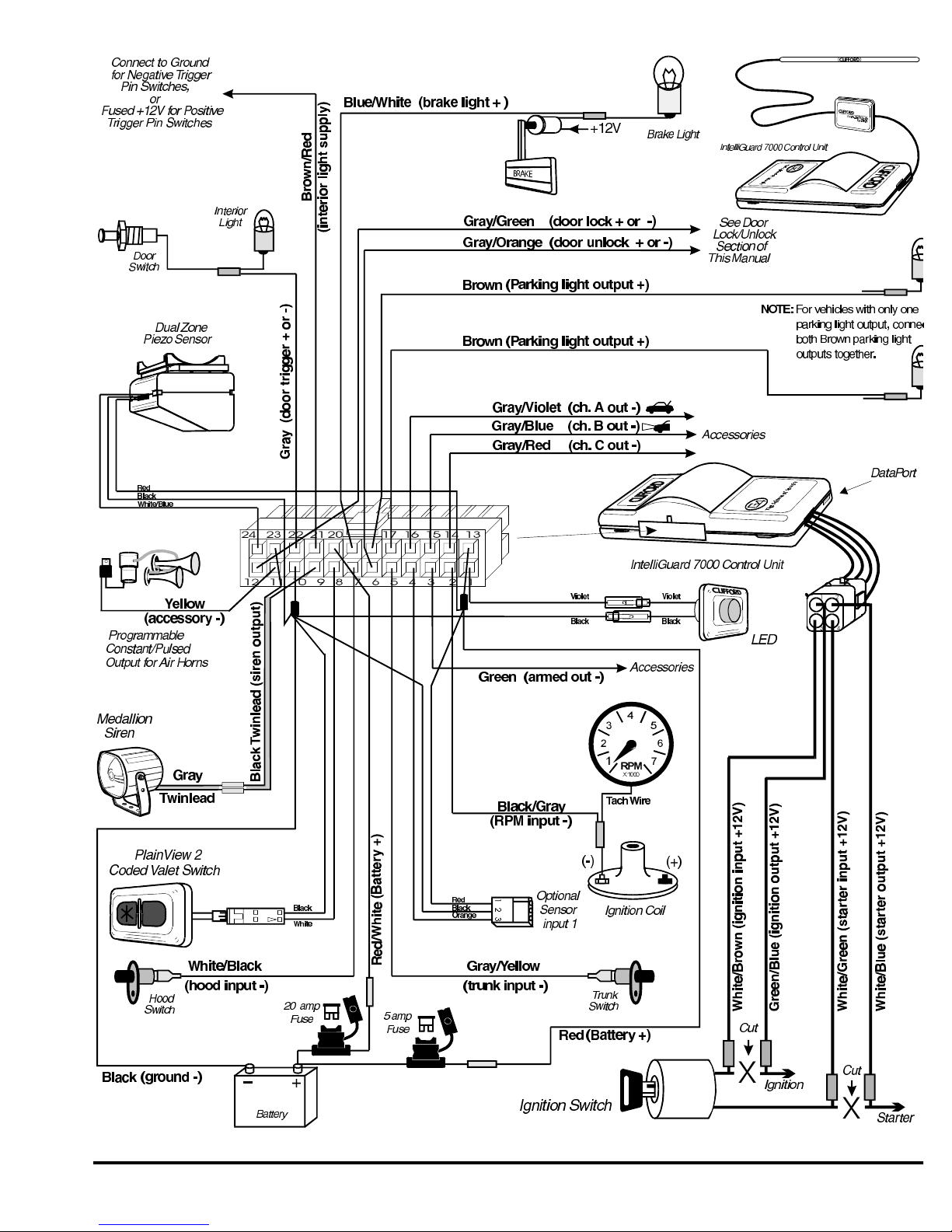
Wiring Description for the 24-Pin Connector
Pin col our Con nects to
1 Violet LED output (+)
2 Black/Gray Ignition coil or tach input
3 Green Armed output (Accessories) (-)
4 Orange Optional sensor input trigger zone (-)
5 Gray/Yellow Trunk trigger switch input (-)
6 Gray/Orange Door unlock output (+ or -)
7 White/Black Hood trigger switch input (-)
8 White PlainView 2 Valet Switch input (-)
9 Black twinlead Medallion Siren output
10 Black Ground for Dual-Zone Piezo and Optional Sensor
11 Yellow Optional airhorns or siren
12 Gray/Green Door lock output (+ or -)
13 Red Power for Dual-Zone Piezo and Optional Sensor
14 Gray/Violet Auxilliary A output (-)
15 Gray/Blue Auxilliary B output (-)
16 Gray/Red Auxilliary C output (-)
17 Brown Parking light output (+)
18 Brown Parking light output (+)
19 Blue/White Brake Light (+)
20 Red/White Battery (+) with 20-amp fuse
21 Brown/Red Interior light supply
22 Gray Door trigger (+ or -)
23 Black twinlead Medallion Siren output
24 White/Blue Remotely Adjustable Dual-Zone Piezo Sensor input
Wiring Description for the 4-Pin Connector
Pin Wire Colour Con nects to
1 Green/Blue Ignition Output (+ 12V)
2 White/Blue Starter Output (+ 12V)
3 White/Brown Ignition Input (+ 12V)
4 White/Green Starter Input (+12V)
2 In tel liGuard 7000/199
Page 3
In tel liGuard 7000/199 3
Page 4

Passenger Compartment Connections
Control Unit and Extended Range Receiver
The IntelliGuard 7000 con trol unit must be in stalled in side the ve hi cle. Un der no cir cum sta nces should the unit
be in stalled un der the hood or other simi larly hos tile en vi ron ment.
1.Select an area behind the dash to mount the control unit using wire ties, but do not permanently af fix it until all wiring and testing
is complete.
2. Plug the extended range receiver in to the control unit. Mount the extended range receiver away fr om the control unit and run
the antenna either up the window pillar and affix it to the windshield, or under the dash, away fro m metal. The position and
location of the receiver will effect remote control range. Do not fold the excess cable or antenna wire. Do not make hard, sharp
bends.
Door Trigger/Interior Light Supply
Please refer to the Door Trigger & Interior Light Supply section in this binder for information on polarity testing and connections.
Central Door Locking System
Please refer to the Door Locks section in this binder for information on circuit types and connections.
LED Status Indicator
Select a prominent location on the dash or console visible through all windows. Discuss placement w ith the owner.
1. Verify there is adequate space to accommodate the LED, then drill a 5/16” (8mm) hole and route the wires through it.
2. Mate the LED connectors to the VIOLET and BLACK wire connectors as shown in the diagram on page 7.
3. Press the LED into place.
PlainView 2 Coded Valet/Programming Switch
1. Discuss placement of the switch with the vehicle owner and avoid placing the switch where it can be pressed accidentally.
2.Verify there is adequate space behind the selected location to accommodate the switch.
3. Drill a 5/16” (8mm) mounting hole, then insert the wires through the hole.
4. Mate the switch’s locking connectors to the WHITE and BLACK locking connector.
5. Remove the adhesive backing and press the switch into place.
Trunk Trigger
Vehicles with a ground-switching trunk light will interface directly with the IntelliGuard 7000 (on positive switching Rolls-Royce vehicles,
use a relay to invert polarity). The switch may be located in or near the trunk latch or at the tru nk light. If a switch cannot be
located, you must add a pin switch in a location away from water channels.
NOTE: If the ve hi cle has a dash board trunk ajar in di ca tor, in stall a 1- amp di ode be tween the light and switch
with the di ode band point ing to ward the switch.
1. Connect the GRAY/YELLOW wire to the trunk switch (between the diode and switch if you added a diode ).
Brake Switch
The brake switch connection is required for the operation of the IntelliGuard 7000’s anti-carjackin g electronics.
1. Turn the ignition to the “ON” position and press the brake pedal to verify that the brake lights ar e operational.
2. Find the one wire that carries +12V when the brake pedal is pressed, then connect the BLUE/WHITE wi re to this wire.
Parking Lights
See the Door Trigger & Parking Lights section in this binder.
4 In tel liGuard 7000/199
Page 5

Passenger Compartment Connections (Continued)
Starter and Ignition Immobilization Circuits
1. Locate the ignition switch wireloom under the dash and use a voltmeter to locate the one wire that carries +12V throughout
BOTH the cranking AND engine running cycles, and 0 volts when the ignition is off.
2. Start the engine, then cut the ignition wire. The engine should stop running.
3. as shown on page 3, connect the WHITE/BROWN wire to the key side of the cut ignition line.
4.Connect the GREEN/BLUE wire to the engine side of the cut ignition line.
5.Use a voltmeter to locate the one wire that carries +12V during the cranking cycle ONLY. Cut this wire, then try to start the
engine. It should not crank.
6. Con nect the WHITE/GREEN wire to the key side of the cut starter line.
7.Connect the WHITE/BLUE wire to the engine side of the cut starter line.
NOTE: The starter cir cuit may carry a very high cur rent. Be cer tain that the starter wire con ne c tions are solid.
Remotely Adjustable Dual-Zone Piezo Sensor
Mount the Dual-Zone Piezo Sensor in the passenger compartment, not in the engine compartment.
1.Firmly mount the sensor near the base of the steering column (if the steering column has a rotating sleeve, firmly screw the sensor
to the interior firewall, kick panel or trunk wall).
2.Mate the sensor to the connector from the control unit with the BLACK, RED, and WHITE/BLUE wires.
3. Adjust the sensor following the instructions provided on page 8.
Auxilliary A with Selectable Output Type
The auxilliary A output (GRAY/VIOLET wire) can be programmed as either pulsed, latched or timed and can be programmed to
operate only when the system is disarmed (e.g., for use as a remote trunk release). Auxilliary A ou tput is activated by pressing the
button or auxilliary A on the remote control. The factory setting is pulsed output (0.5 second gr ound). The latched output
stays at ground until the trunk button or auxilliary A is activated a second time, and the timed ou tput stays at ground for any
selected duration between one second and four minutes. Current is limited to 0.15 amp. See Installer-Programmable Features on page
11 for information on programming the output type and/or disabling operation while the system is di sarmed.
Auxilliary B with Selectable Output Type
The auxilliary B output (GRAY/BLUE wire) can be programmed as either pulsed, latched or timed and i s activated by pressing the
button on the companion remote or button 5 on the master remote control. The factory setting is pu lsed output (0.5 second
ground). The latched output stays at ground until the remote control button is pressed a second ti me, and the timed output stays at
ground for any selected duration between one second and four minutes. Current is limited to 0.15 am p. See Installer-Programmable
Features on page 11 for information on programming the output type.
Auxilliary C with Selectable Output Type and AutoActivation
The auxilliary C output (GRAY/RED wire) can be programmed as either pulsed, latched, or timed and i n addition, can also be
programmed to automatically activate every time the system is armed using the remote control (e.g., for window all-close). The
output is activated by pressing the and ✱ buttons on the companion remote or button 7 on the master remote control. Current is
limited to 0.15 amp. AutoActivation is perfect when programmed as a timed-output to close the power windows and sunroof on vehicles
that have an all-close feature. See Installer-Programmable Features on page 11 for more information on programming output type and/or
enabling the AutoActivation feature.
Engine Bay Connections
Medallion Siren
Mount the siren in the engine compartment away from hot or moving parts and where it cannot be reac hed from under the vehicle,
preferable opposite the exhaust system. Point the siren down to avoid water collection (see the il lustration).
1.You must firmly secure the siren to the engine bay firewall or an fender well using all three sheet metal screws supplied.
2.Us ing the sup plied con nec tor, fasten the GRAY twin lead wire coming from the siren to the BLACK twinlead from the 24-pin
connector on the control unit.
In tel liGuard 7000/199 5
Page 6

Engine Bay Connections (Continued)
RPM Monitoring
This is required for both RPM-activated automatic door locking and for BlackJax anti-carjacking fea tures. See the RPM Monitoring
section in this binder for information.
Hood Trigger
Vehicles with a ground-switching hood pin switch interface directly with IntelliGuard 7000 (on posi tive switching Rolls-Royce vehicles, use
a relay to invert polarity). If a switch cannot be located, you must add a pin switch in a location away from water channels.
1. Connect the WHITE/BLACK wire to the hood pin wire (between the diode and pin switch if a diode was added).
NOTE: If the vehicle has a dashboard hood ajar indicator, install a 1-amp diode between the light a nd switch
with the diode band pointing toward the switch.
Final Wiring Connections
1. Connect the RED wire to the 5-amp fuseholder as shown on page 3.
2.Connect the RED/WHITE wire to the 20-amp fuseholder as shown on page 3.
3.Attach the two fuseholders to the battery positive cable clamp.
4. Attach the BLACK wire to the battery negative cable clamp.
NOTE: Power and test ac ces so ries af ter the ba sic sys tem has been tested. In di vidu ally fuse all ac ces sory power
con nec tions. In di vidu ally fuse all +12V fuse panel con nec tions.
SmartPowerUp™ 2
SmartPowerUp 2 ensures that the system powers up in the same state (disarmed, armed or valet mode) it was in when power was removed.
When you first power up the IntelliGuard 7000, it will silently enter the disarmed state.
Delayed Courtesy Lights
Some vehicles have a courtesy light delay or dimming circuit, which interferes with an alarm being able to detect the door trigger upon
remote arming. If the delay or dimming lasts more than 5 seconds, no special connections or testing are needed, simply turn on the Delayed
Courtesy Lights feature as noted in the Installer-Programmable Features section on page 11. Please note that since this feature sets the
system to arm the instant the courtesy lights turn off, the Door Ajar Warning feature will not be a vailable.
Remote Control Operation
The IntelliGuard 7000 comes with two ergonomically designed remote controls. Up to two more ACG 2 r emote controls can be
added to the IntelliGuard 7000 system. Due to the ACG 2 feature on the IntelliGuard Series systems , older Clifford ACG and
non-ACG remotes are not compatible with the IntelliGuard 7000.
16-Channel Mas ter Re mote Con trol Op era tion
To transmit either channel 1, 2, 3 or 4: Press button 1, 2, 3 or 4. The LED indicator on the remote
control will flash once every second: this indicates level 1.
To transmit either channel 5, 6, 7 or 8: Press the LevelShift button once. This shifts buttons 1–4 to
level 2 (channels 5–8). Then press the desired button within the next 5 seconds. For instance, to
transmit channel 5, press the LevelShift button once, then press button 1. The LED indicator on the
remote control flashes twice, pauses, flashes twice, etc.: this indicates level 2.
To transmit channel 9, 10, 11 or 12: Press the LevelShift button twice. This shifts the buttons to level 3 (channels 9–12). Then press
the corresponding button within the next 5 seconds. For instance, to transmit channel 10, press the LevelShift button twice, then press
button 2. The LED on the remote control flashes three times, pauses, flashes three times, etc.: thi s indicates level 3.
To transmit channel 13, 14, 15 or 16: Press the LevelShift button three times. This shifts the buttons to level 4 (channels 13–16).
Then press the corresponding button within the next 5 seconds. For instance, to transmit channel 14 press the LevelShift button three
times, then press button 2. The LED on the remote control flashes four times, pauses, flashes four times, etc.: this indicates level 4.
6 In tel liGuard 7000/199
Page 7

Remote Control Operation (Continued)
NOTE: One sec ond af ter you stop trans mit ting levels 2, 3 or 4 (chan nels 5–16), the re mote con trol
auto mati cally re turns to level 1 (chan nels 1–4).
Remote Control Channel Assignments
Chan nel # Func tion Chan nel # Func tion
1 Arm/Disarm 9 Remote Valet Mode
2*
3 Silent Arm/Disarm 11* Manual Transmission/AutoStart Enable*
4 Unassigned or IntelliStart 4 remote engine starting* 12* Unassigned*
5*
6* SmartWindows 4 Accessory* 14* Unassigned*
7*
8* Unassigned* 16* Unassigned*
* These channels can be assigned to control other IntelliGuard systems and accessories on multiple vehicles.
Activate Optional Auxilliary A Wired Accessory
(usually remote trunk release)*
Activate Optional Auxilliary B Wired Accessory
(Usually remote timed headlight activation or turbo
timer)*
Activate Optional Auxilliary C Accessory
(Usually window all-close or IntelliVoice 4)*
10 Optional Sensor Override
13* Unassigned*
15* Dual Zone Piezo Sensor Adjustment*
Companion Remote Control Operation
Func tion Press but ton(s)
Arm/Disarm
Activate Wired Auxilliary A Accessory*
(usually remote trunk release)*
Silent Arm/Disarm
IntelliStart 4 Accessory*
Activate Auxilliary B Wired Accessory*
(such as timed headlight activation)
SmartWindows 4 Accessory*
Activate Wired Auxilliary C Accessory (IntelliVoice 4
Accessory or Window All-Close)*
Unassigned*
Remote Valet Mode Entry*
Optional Sensor Override
*These channels can be assigned to control other ACG 2 systems and
accessories on the customer’s other vehicles.
+ ✱
✱
+
+ ✱
+
+ ✱
+
In tel liGuard 7000/199 7
Page 8

Sensor Adjustment
1.Disarm the system with the remote control.
2. Transmit channel 15 on the master remote (LevelShift three times, then button 3). You will hear one chirp and the LED will turn on.
3. Test the Piezo Sensor’s primary zone by thumping the window pillar firmly. You will hear a siren chirp when the primary zone is
triggered.
To change the sensitivity of the primary zone, press and release button 2 to increase sensitivity or button 4 to decrease sensitivity.
To rapidly increase or decrease several steps, press and hold the button. For each sensitivity incr ease, you will hear a higher and
higher pitched confirmation chirp. For each sensitivity decrease, you will hear a lower and lower p itched confirmation chirp. Two
LoudChirps indicate minimum and maximum settings of the 32-step range of settings. You may now pres s button 3 to adjust the
warning zone, or press button 1 to fully exit the Piezo Sensor adjustment mode (you will hear 3 chirps).
To change the sensitivity of the warning zone, press button 3 (you’ll hear 1 chirp). Then use the same procedure as above, but this
time, thump the window pillar very softly. When done, press button 1 to reselect the primary zone (you will hear 2 chirps), then
button 1 again to fully exit Piezo Sensor adjustment mode (you will hear 3 chirps).
4.Repeat the preceding steps as required. An improperly adjusted sensor will cause the IntelliGuard 7 000 to false alarm or not
respond properly to a genuine threat.
Re mote con trolled over ride of Optional Sen sor
Transmitting channel 10 on the master remote control (LevelShift button twice, then button 2), or pressing the and
buttons on the companion remote, at any time while the system is armed will override the optional s ensor. This comes in handy when
you must temporarily leave a pet or a passenger in the vehicle. The channel 10 optional sensor over ride is visually confirmed with 4
flashes of the parking lights. The sensor is automatically restored the next time you arm.
FACT—False Alarm Control and Test
The system microprocessor automatically checks for another activated sensor or trigger before sound ing the siren a second time, thus
preventing any further false alarms. If you wish to test FACT, simply:
1. Arm the IntelliGuard 7000 with the re mote con trol.
2. Wait 10 seconds after the interior light turns off, then trigger the Piezo Sensor to activate the s iren.
3. Do not disarm the system, let the siren complete its cycle.
4.Attempt to trigger the sensor again. The alarm should be silent.
5. Unlock and open a door. The alarm should sound immediately. You may now disarm.
Eight-Event TotalRecall
The system’s nonvolatile memory records the identity of the last eight activated or malfunctioning triggers and sensors:
NOTE: The CliffNet Wizard dis plays the Eight- Event To tal Re call data in a graphi cal for mat.
1.With the ignition OFF, press and hold the unmarked side of the PlainView 2 Switch.
2. Use the remote control arm, and then again to disarm, and then release the button.
3. The LED will flash 1–10 times, pause, then flash 1–10 times, etc. Write down the number of flashes in each cycle.
4.Refer to the following chart. The first number you wrote down was the most recently activated trigg er or sensor. The next number
is the second most recent, and so on up to as many as the last eight activations.
8 In tel liGuard 7000/199
Page 9

Eight Event TotalRecall (Continued)
s through a user-friendly, graphical
ser-Programmable Features.
button the same number of times as the feature’s row number. You’ll hear a
Num ber of LED flashes be tween pauses Trig ger/sen sor in di ca tion
2 flashes Dual-Zone Piezo Sensor
3 flashes Optional Sensor
4 flashes Door Trigger
5 flashes 0Trunk Trigger
6 flashes Hood Trigger
7 flashes
8 flashes
9 flashes BlackJax
10 flashes System Power Interruption
ignition or start the engine while the system was armed
valet codes were entered while the system was in BlackJax mode
An attempt was made to turn on the
More than three consecutive incorrect
5. If a sensor is often activated, decrease that sensor’s sensitivity (or reposition the sensor, if ne cessary). If a certain trigger is often
activated, check pin switch operation, verify that the pin switch is not exposed to moisture and ch eck the trigger wire for possible
shorting.
Programmable Features
IntelliGuard 7000 comes from the factory with its features preprogrammed as noted in bold text in the tables on pages 10 and 11.
Some features can be programmed by the installer or the user, others can only be programmed only by the installer.
Using the CliffNet Wizard Pro
The CliffNet Wizard Pro provides an intuitive access to all installer and user-programmable feature
user interface. Because CliffNet Wizard Pro is Windows™-compatible, most operations can be accomp lished by simply pointing and
clicking a mouse. CliffNet Wizard Pro totally eliminates complicated programming charts and length y button pressing sequences.
Please refer to the CliffNet Wizard Pro User’s Guide for more programming information if you are using the CliffNet Wizard Pro.
Otherwise, for manual programming refer to the tables provided in the following sections.
Programming the User-Selectable Features
1. Write down the column (across) number and row (down) number of the feature(s) you wish to program.
2. Turn the ignition to the “ON” position or start the engine.
3.Enter the factory preset valet/programming code of “2” by pressing the PlainView 2 Switch’s ✱ button two times, then press the
unmarked button.
4.After entering the code, press and hold the ✱ for about 3 seconds until you hear one siren chirp and the LED turns on to
acknowledge program mode entry. The IntelliGuard 7000 is now in the “Feature Select” position for U
5. Select the feature column: Press the unmarked button the same number of times as the column number. Pause. You will then hear
the same number of chirps as the column number you have selected, audibly confirming your selection .
6.Within five seconds, select the feature row: Press the ✱
chirp each time you press the unmarked side to help you count.
7.If there is a NOTE for the selected feature, perform the actions noted.
8. Pause. You will hear either one or two chirps: two chirps = ON, one chirp = OFF.
9. You can select another feature, or you can exit program mode:
a. To select another feature in that same column, repeat step 6 within the next five seconds (after fi ve seconds, three chirps
indicate that the IntelliGuard 7000 is now back in the “Feature Select” position).
b. To select a different feature column, repeat step 5.
c. To exit program mode, turn the ignition off (you’ll hear three chirps and the LED will turn off to indicate exit of program
mode), or wait 60 seconds and the IntelliGuard 7000 will automatically exit program mode.
In tel liGuard 7000/199 9
Page 10

User-Programmable Features
User-Programmable Features (1 Chirp = OFF, 2 Chirps = ON)
Fea ture
Select
✱ 1
✱ 2
✱ 3
✱ 4
✱ 5
✱ 6
✱ 7
Unmarked 1 Unmarked 2 Unmarked 3 Unmarked 4
AutoProgram New Master
Remote
NOTE 1
Personalized Siren Sounds
Play Siren Sounds
Siren Duration
(30/60/90 seconds)
AutoLock
(Off/Instant/RPM-Dependent)
(1 chirp/2 chirps/3 chirps)
AutoUnlock
(Off/On)
(1 chirp/2 chirps)
Re set All to Fac tory Set tings
(ex cept re mote controls and
valet code)
NOTE 2
Chirps
(Off/LoudChirps/QuietChirps)
(1 chirp/2 chirps/3 chirps)
Headlight Reminder
(Off/On)
Remote Valet Feature
(Off/On)
(1 chirp/2 chirps)
AutoStart*
(Neither/Battery/Temperature/Both)
(1 chirp/2 chirps/3 chirps/4 chirps)
BlackJax
(Off/On)
(1 chirp/2 chirps)
Clear All Remotes
NOTE 3
Valet Code
SHOULD ONLY BE
PROGRAMMED BY THE VEHICLE
OWNER
AutoArming
(Off/On)
(1 chirp/2 chirps)
AutoArm & Lock
(Off/On)
(1 chirp/2 chirps)
NOT USED
FACT
(Off/On)
(1 chirp/2 chirps)
NOT USED
NOT USED
NOT USED
Auxilliary A Accessory or
Auxilliary B Accessory or
Timed Headlight Activation
with Secondary Remote
Window Rolldown/Venting
with Secondary Remote
with Secondary Remote
Arm/Disarm with
Secondary Remote
NOTE 4
Trunk Release with
Secondary Remote
NOTE 5
Silent Arm/Disarm with
Secondary Remote
NOTE 5
Remote Start with
Secondary Remote
NOTE 5
NOTE 5
(Requires Optional
SmartWindows 4)
NOTE 5
Remote Valet Mode
NOTE 5
*Requires optional IntelliStart 4
NOTE 1: Press button 1 on the 16-channel master remote, you will hear one chirp. Press button 1 again, you will hear two
n
chirps.
NOTE 2: You will hear two chirps when all features are reset.
n
NOTE 3: When you hear two chirps, all remote controls will have been erased from the system memory. You mu st now add
n
the new and/or existing remote controls to the system (i.e., AutoProgram each remote that will be u sed with the
IntelliGuard 7000).
NOTE 4: Programs a 4-channel secondary, 16-channel master, or any other remote control from another Intell iGuard
n
system to arm or disarm the vehicle. For instance, to set button 13 of the other car’s master remot e control to arm/disarm
the system, select column 4, row 1, then transmit channel 13 from the remote you are programming. T he system will
respond with one chirp. Immediately transmit channel 13 again. The system will respond with two chi rps. Button 13 of the
other vehicle’s remote will now arm/disarm the system.
NOTE 5: This feature can be programmed onto the remote control of another IntelliGuard system, after that remote has
n
been programmed to arm/disarm this system. Select the row and column number, then transmit the unus ed button on the
other remote that you want to use to perform that function. The IntelliGuard Millennia will respond with the same number
of chirps as the row number. Please note that you must first set a button on the remote that will a rm/disarm the system
(column 4, row 1) before these others will be accepted.
10 In tel liGuard 7000/199
Page 11

Installer-Programmable Features
telliGuard 7000 cor rectly. If the sys tem does
To access the installer-programmable features, use the procedure defined in the User-Programmable s ection, but in step 4, hold and
press the ✱ side of the PlainView 2 Switch for 15 seconds. You will hear three confirmation chirps indicating that the system is in
installer-program mode.
Table of Installer-Programmable Features (1 chirp = OFF, 2 chirps = ON)
Fea ture
Select
✱ 1
✱ 2
✱ 3
✱ 4
✱ 5
✱ 6
Unmarked 1 Unmarked 2 Unmarked 3
Single/Double Lock Pulse
(1 chirp/2 chirps)
Single /Double Unlock Pulse
(1 chirp/2 chirps)
Lock/Unlock Pulse
3 second/1 second
(1 chirp/2 chirps)
Program Door Polarity
(Positive/Negative)
(1 chirp/2 chirps)
Program RPM
See Mandatory RPM
Programming section in this
binder
Aux il iary Si ren Out put
(Constant/Pulsed)
(1 chirp/2 chirps)
Accessory Output Timer
Duration
(10 seconds )
See NOTE 1
Auxiliary A Type
(Pulsed /Timed/Latched)
(1 chirp /2 chirps/3 chirps)
Auxiliary BType
(Pulsed /Timed/Latched)
(1 chirp /2 chirps/3 chirps)
Auxiliary CType
(Pulsed /Timed/Latched)
(1 chirp /2 chirps/3 chirps)
Diesel Engine/Gas Engine
(1 chirp/2 chirps)
(For IntelliStart 4 only)
NOT USED
Door Ajar Warning /Delayed
Auxiliary A (trunk release)
AutoActivate Auxiliary C upon
Learn PageMate 4 ID or
Program SmartWindows 4
Courtesy Lights
(1 chirp/2 chirps)
Interlock
(On/Off)
Auxiliary B Interlock
(On/Off)
Auxiliary C Interlock
(On/Off)
Remote Arming
(On/Off)
(Requires Optional
SmartWindows 4)
NOTE 1: Once this feature is selected, one chirp is provided to indicate that the timer has started. You can set this anywhere
n
from one second to four minutes. When the desired duration has been reached, press the unmarked side of the PlainView 2
switch. The system responds with two chirps to confirm the new system timer duration.
System Checklist & Troubleshooting
The fol low ing check list and trou ble shoot ing tips will as sure that you have in stalled the In
not re act as noted, fol low the trou ble shoot ing tip(s) de noted with a black box be low that it em, then re peat the step. Each suc ces sive
step re quires that the pre vious step has been com pleted as in di cated.
The CliffNet Wizard simplifies the troubleshooting process by providing system diagnostic informati on in a graphical format. All
system settings are provided at-a-glance, and adjustments to the system settings can be made with a click of a mouse. This reduces
the amount of time required for performing the following tests.
Step 1.
Re- enable the cour tesy lights.
In step 1 of the Important Information sec tion in this binder, the in te rior cour tesy lights were disabled. You must now re-enable
the courtesy lights by re placing the fuse you re moved or re set the cour tesy light switch back t o its nor mal “DOOR” po si tion bef ore
pro ceed ing.
In tel liGuard 7000/199 11
Page 12

System Checklist & Troubleshooting (Continued)
Step 2.
Test the Im mo bi li za tion cir cuits.
Arm the IntelliGuard 7000 (either from inside or outside the vehicle) and wait 10 seconds. Turn the ignition to the “ON”
n
position.
o Engine does not respond. This is the correct response, proceed to the immobilization test.
o Engine starts or cranks. The starter/ig ni tion/fuel pump or immobilization cir cuits have been mis wired. Care fully re tes t the
ve hi cle wires as noted in the Starter and Ig ni tion Immobilization Cir cuits section on page 9. Be sure the ignition input/output
is correct!
o Engine still starts or cranks after retesting all the wiring as noted on page 9, check the power and ground connections.
Then make sure the fuses are in the fuseholders, verify the control unit connectors are securely fa stened, verify the ignition
input and output wires are connected to the true ignition line instead of a 12V or accessory line, and verify that the
transmitters are programmed correctly.
Step 3.
Test the chirps.
Close all doors and arm the IntelliGuard 7000 by pressing button 1 on the remote control.
2 Chirps: This is the correct response. Proceed to step 4.
n
4 Chirps: If you hear 4 chirps ei ther im me di ate ly or 5-10 sec onds af ter the ini tial two chirps, a tri g ger or sen sor is open or
n
active, or the ve hi cle has de layed cour tesy lights and the De layed Cour tesy Lights fea ture has not been programmed on. Dis arm
with the re mote con trol, en ter the ve hi cle and turn on the ig ni tion. The LED will flash 1–10 times, pause, then re peat the same
number of flashes (the flash cy cle re peats five times for your con ven ience). Ref er to the foll owing chart.
Num ber of LED flashes be tween pauses Trig ger/sen sor in di ca tion
2 flashes Dual-Zone Piezo Sensor
3 flashes Optional Sensor
4 flashes* Door Trigger*
5 flashes Trunk Trigger
6 flashes Hood Trigger
7 flashes
8 flashes
9 flashes BlackJax
10 flashes Power Interruption
An attempt was made to turn the ignition “ON” or start the engine while the
system was armed
More than three consecutive incorrect valet codes were entered while the system
was in BlackJax mode
* If the de layed cour tesy lights fea ture is ac ti vated, this trig ger/sen sor in di ca tion will not be pro vided.
o If the door trig ger is in di cated, ac ti vate the de layed cour tesy lights fea ture.
No chirps. If there are no chirps, ver ify that the Chirps fea ture (col umn 2, row 1) is “On” and check the w ir ing con nec tions as
n
noted in the Me dal lion Si ren sec tion on page 9.
NOTE: If none of the troubleshooting techniques described in steps 3 - 7 corrects the problem, perf orm the
following diagnostics:
o Make sure the fuses are in the fuse hold ers.
o Check the power and ground con nec tions.
o Ver ify that the con trol unit con nec tors are prop erly in serted into the con trol unit.
o Verify that the ig ni tion in put and out put wires are con nected to the true ig ni tion line inst ead of a 12V line. Find the true
ig ni tion line by fol low ing steps 1-4 of the Starter and Ig ni tion Immobilization Cir cuits sec tion on page 9.
o Ver ify that the trans mit ters are pro grammed cor rectly.
NOTE: If the 20- amp fuse blows upon arm ing:
o Disconnect the IntelliGuard 7000’s two parking light wires, replace the 20-amp fuse and rearm. If t he fuse does not blow,
one (or both) of the ve hi cle’s parking light wires is short ing. Find and cor rect the short(s), re con nect the parking light
wires, then re arm.
12 In tel liGuard 7000/199
Page 13

System Checklist & Troubleshooting (Continued)
arked side, it should read 3
e valet code has been changed.
Step 3. Continued
o If the fuse blows while the parking light wires are dis con nected, the door locks are not wired co r rectly. Re con nect the
ve hi cle’s power lock ing sys tem to its origi nal con di tion, then re test the volt ages as in d i cated in the Door Locks sec tion of
this binder and wire the locks as in di cated, then re place the 20- amp fuse.
Step 4.
Test the parking lights.
Arm the sys tem by press ing but ton 1 on the re mote con trol.
Two flashes. This is the correct response, proceed to step 5.
n
One flash. If the parking lights flash only once, the IntelliGuard 7000 had pre vi ously AutoArmed it self pas sively and by
n
press ing but ton 1 the sys tem dis armed (re mote dis arm ing is ac knowl edged with one parking l ight flash). Re peat step 1.
No flashes. If no flashes, ver ify the parking light bulbs are op era tional. If not, they must be re placed. I f so, re peat steps 1-5 of
n
the P arking Lights sec tion in this binder.
Only one side flashes. If only the right or the left side parking lights flash, see the Parking Lights sec tion in this binder.
n
Step 5.
Test the door locks.
Arm the sys tem by press ing but ton 1 on the re mote con trol.
Doors lock. This is the correct response, proceed to step 6.
n
Doors do not lock. You ei ther se lected the wrong door lock dia gram, programmed the wrong door lock polarity or con nected
n
the wires in cor rectly. Re con nect the ve hi cle’s power lock ing sys tem to its origi nal con di tion, then re test the volt ages as
in di cated in the Door Locks sec tion of this binder and wire the locks as in di cated.
WARN ING: If the doors do not lock, DO NOT ac ti vate the ve hi cle’s lock switches. If the locks h ave been
mis wired, do ing so may dam age the IntelliGuard 7000 con trol unit, the ve hi cle’s elec tri cal sys tem and/or the
power lock servo mo tors.
Doors unlock. You ei ther se lected the wrong door lock dia gram or con nected the wires in cor rectly. Re con n ect the ve hi cle’s
n
power lock ing sys tem to its origi nal con di tion, then re test the volt ages as in di cated in t he Door Lock ing/Un lock ing sec tion of
this binder and wire the locks as in di cated.
Only one door locks. You ei ther se lected the wrong door lock dia gram or con nected the wires in cor rectly. Re con n ect the
n
ve hi cle’s power lock ing sys tem to its origi nal con di tion, then re test the volt ages as in d i cated in the Door Lock s sec tion of this
binder and wire the locks as in di cated.
Step 6.
Test the LED.
Arm the system by pressing button 1 on the remote control.
Flashes repeatedly. This is the correct response, proceed to step 7.
n
No flashes. If the LED does not flash, ver ify that the LEDs VIO LET and BLACK wires are sol idly con nected to the same
n
colour wires on the IntelliGuard 7000’s wire loom. Warn ing: This is a 2- volt LED, test ing with 12 volts will de stroy the LED.
Step 7.
Test the Valet Switch.
Test the valet code and switch operation. Use the instructions provided on page 7 to enter program ming mode. If the system
n
enters programming mode, the switch and valet code are in operating order. If not, perform the fol lowing tests:
Test the WHITE/BROWN wire, ignition input and verify it has +12V when the ignition is turned ON and +0V when the
n
ignition if OFF. If not refer to Starter and Ignition Immobilization Circuits on page 5.
Test the WHITE wire at the control unit connector. It should rest at 5 volts. When pressing the m
n
volts and when pressing the unmarked side it should read 0 volts. If any reading is incorrect, mov e the voltmeter to the
BLACK wire at the valet switch. It should read 0 volts at rest, 0 volts when the marked side marke d is pressed, and 0 volts
when the unmarked side is pressed. If the BLACK wire tests correctly and the WHITE wire does not, replace the switch. If
the BLACK wire tests incorrectly, repair the ground circuit. If both wires test correctly, then th
Use the CliffNet Wizard to reset the valet code.
Step 8.
Test the Dual- Zone Piezo Sen sor.
Arm the system and tap the car softly with your fist. The following should occur:
n
o Warning buzzer sounds. Proceed to the next test.
Hit the car firmly with your fist. The follwoing should occur:
n
o Alarm triggers. Proceed to step 10.
If either of these test fail, adjust the sensor using the remote control.
In tel liGuard 7000/199 13
Page 14

System Checklist & Troubleshooting (Continued)
Step 9.
Test the dis arm func tion.
Disarm by pressing remote control button 1. The following should occur:
n
o Siren chirps once. If the siren does not chirp once, refer to step 3.
o Parking lights flash once. If the parking lights do not flash once, refer to step 4.
o LED stops flashing. If not refer to step 6.
o Doors un lock. If not refer to step 5.
o Immobilizer cir cuits im me di ate ly disen gage (test this by turn ing the key in the ig ni tion switch; the en gine should crank,
start and idle nor mally). If the Immobilizer circuits do not disengage, refer to step 2.
o In te rior cour tesy light(s) turn on and stay on for 30 sec onds or un til the ig ni tion is turned on, which ever oc curs first.
o If the in te rior light(s) do not turn on, ver ify that you re placed the interior light fuse you r e moved or have turned the
lights back on as noted in step 1 of this sec tion.
o Check the IntelliGuard 7000’s 10- amp fuse. If the fuse blew when you dis armed, the ve hi cle uses a posi tive door trig ger
and you con nected the in te rior light sup ply wire to ground in stead of +12 volts. Re place the 10-amp fuse and retest.
o Check the door trig ger cir cuit. See step 8 for more information on testing the door trigger circ uit.
Step 10.
Test the door trig ger cir cuit.
Rearm the sys tem. Wait at least 10 seconds (if the vehicle has delayed or dimming courtesy lights, be sure to wait until the interior
lights have turned off). Use the key to unlock and open the driver’s door.
Siren sounds, parking lights flash repeatedly. This is the correct response, proceed to step 11. (You can silence the siren by
n
press ing the button on the re mote con trol once or disarm by pressing the button twice.)
Siren does not sound immediately. If the alarm does not sound im me di ate ly when one of the doors is opened, make sure that
n
that door’s pin switch is work ing prop erly and, when open, is con sis tently show ing less than 1 .5 volts if the ve hi cle has
negative- switching door trig gers or more than +11 volts if the ve hi cle has positive- switching door trig gers, also make sure the
pin switch is connected to the correct wire. If not, then the door pin switch (or pin switches) is ei ther de fec tive or in need of
clean ing.
Step 11.
Test the trunk trig ger cir cuit.
Arm the system, then use the key to unlock the trunk.
Si ren sounds im me di ate ly, parking lights flash re peat edly. This is the correct response, proceed to step 12. (You can silence
n
the siren by press ing but ton 1 on the re mote con trol or disarm by pressing button 1 two times.)
Alarm does not sound immediately. If the alarm does not sound im me di ate ly, make sure that the trunk pin switch is work ing
n
prop erly and, when open, is con sis tently show ing less than 1.5 volts. Also make sure the trunk pin switch is connected to the
correct wire. If not, the trunk pin switch must be thor oughly cleaned or re placed.
Step 12.
Test the hood trig ger circuit.
Arm the system, then open the hood. The following should occur:
Si ren sounds im me di ate ly, parking lights flash re peat edly. This is the correct response, proceed to step 13. (You can silence
n
the siren by press ing but ton 1 on the re mote con trol or disarm by pressing button 1 two times.)
Alarm does not sound immediately. If the alarm does not sound im me di ate ly, make sure that the hood pin switch is work ing
n
prop erly and, when open, is con sis tently show ing less than 1.5 volts. If not, the hood pin swit ch must be thor oughly cleaned or
re placed.
Step 13.
Test the AutoArming fea ture.
Turn the ignition “ON,” start the vehicle, and let the car idle for 10 seconds. Turn the ignition “OFF,” then open and close the
door. Wait five seconds.
Parking lights flash twice. 25 seconds later, the vehicle is passively armed indicated by a rapidly flashing LED . This is the
n
correct response, proceed to step 14.
System does not passively arm.
n
o Make sure that Instant AutoArming has been programmed using the instructions on page 14.
o Verify the door trigger connection (see step 9).
Step 14.
Test the In stant AutoArming By pass.
Disarm the system. Roll the windows down and turn the ignition to the “ON” position, then turn the ignition “OFF.”
One Chirp. This is the correct response, open and close the door then wait 30 seconds to insure the system d oes not passively
n
arm.
14 In tel liGuard 7000/199
Page 15

System Checklist & Troubleshooting (Continued)
Step 15.
Test remote control range.
Stand approximately 50 feet from the vehicle and use the remote control to arm and disarm the syste m.
The IntelliGuard 7000 will re spond with the pre vi ously noted in di ca tions for arm ing and dis arm ing. If not:
n
o Re po si tion the external receiver as high as possible high up un der the dash, or as high as poss ible along side the windshield
pillar and as far as pos si ble from heavy wire looms and metal. Rotate the external receiver 90 d egrees and re-test.
o Make sure that the re mote con trol bat tery meas ures at least 11 volts while trans mit ting.
o Make sure that the volt age at the con trol unit be tween the 5- amp fused power line and each of t he two ground lines
meas ures at least 12.0 volts when triggered (if less, make sure both chas sis grounds are solid; i f the grounds are solid, the
ve hi cle battery may need charg ing, serv ic ing or re place ment).
o Make sure that no accessories have been tapped in to the solid RED or solid BLACK power wires.
Step 16.
Com plete and pro vide all nec es sary pa per work in clud ing:
User’s Manual must be given to the customer.
n
Adhere the Clifford window decals to the vehicle’s windows.
n
Step 17.
Dem on strate Ba sic Sys tem Operation
Remote Operations:
n
o Arming/disarming and locking/unlocking
o Panic Feature
o Remote Valet Mode Activation
o Dual-Zone Piezo Sensor Override
o Accessory operation
AutoArming and AutoArming Bypass
n
Immobilization
n
Valet code entry
n
User-programming mode
n
In tel liGuard 7000/199 15
 Loading...