

Page 1
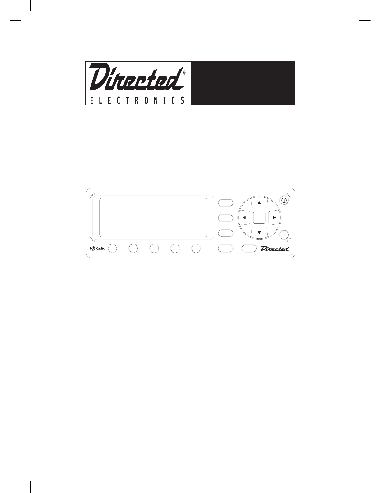
Directed HD Car Connect Radio
User’s Manual
SEL
MENU
DISP
BAND
1
2
3
4
5
BANK SEEK
Model DMHD-1000
DMHD1000
USER’S MANUAL
Page 2

© 2006 Directed Electronics, all rights reserved
2
LIMITED ONE-YEAR CONSUMER WARRANTY
Directed Electronics (herein “DIRECTED”) promises to the original purchaser, to replace this
product should it prove to be defective in workmanship or material under normal use, for a
period of one-year from the date of purchase from the dealer as indicated by the date code
marking of the product. During this one-year period, there will be no charge for this replacement
PROVIDED the unit is returned to DIRECTED, shipping pre-paid. This warranty is non-transferable and does not apply to any unit that has been modified or used in a manner contrary to its
intended purpose, and does not cover damage to the unit caused by installation or removal of
the unit. This warranty is void if the product has been damaged by accident or unreasonable use,
neglect, improper service or other causes not arising out of defects in materials or construction.
Units which are found to be damaged by abuse resulting in thermally damaged voice coils are
not covered by this warranty but may be replaced at the absolute/sole discretion of DIRECTED.
ALL WARRANTIES, INCLUDING BUT NOT LIMITED TO EXPRESS WARRANTY, IMPLIED WARRANTY,
WARRANTY OF MERCHANTABILITY, FITNESS FOR PARTICULAR PURPOSE, AND WARRANTY OF
NONINFRINGEMENT OF INTELLECTUAL PROPERTY ARE EXPRESSLY EXCLUDED TO THE MAXIMUM
EXTENT ALLOWED BY LAW, AND DIRECTED NEITHER ASSUMES NOR AUTHORIZES ANY PERSON
TO ASSUME FOR IT ANY LIABILITY IN CONNECTION WITH THE SALE OF THE PRODUCT. DIRECTED
HAS ABSOLUTELY NO LIABILITY FOR ANY AND ALL ACTS OF THIRD PARTIES INCLUDING ITS
AUTHORIZED DEALERS OR INSTALLERS. IN NO EVENT WILL DIRECTED BE LIABLE FOR ANY INCIDENTAL, SPECIAL OR CONSEQUENTIAL DAMAGES (INCLUDING LOSS OF PROFITS) AND IN NO
EVENT, SHALL DIRECTED’S LIABILITY EXCEED THE PURCHASE PRICE PAID BY PURCHASER FOR
THE PRODUCT. Some states do not allow the exclusion or limitation of incidental or consequential damages, so the above limitation or exclusion may not apply to you. Some states do not
allow limitations on how long an implied warranty lasts, so the above limitation may not apply
to you. Unit must be returned to DIRECTED, postage prepaid, with bill of sale or other dated
proof of purchase bearing the following information: consumer’s name, telephone number, and
address, authorized dealer’s name and address, and product description. Note: This warranty
does not cover labor costs for the removal and reinstallation of the unit. IN ORDER FOR THIS
WARRANTY TO BE VALID, YOUR UNIT MUST BE SHIPPED WITH PROOF OF PURCHASE FROM AN
AUTHORIZED DIRECTED DEALER. BY PURCHASING THIS PRODUCT, THE CONSUMER AGREES AND
CONSENTS THAT ALL DISPUTES BETWEEN THE CONSUMER AND DIRECTED SHALL BE RESOLVED
IN ACCORDANCE WITH CALIFORNIA LAWS IN SAN DIEGO COUNTY, CALIFORNIA.
Page 3

© 2006 Directed Electronics, all rights reserved
3
TABLE OF CONTENTS
Congratulations . . . . . . . . . . . . . . . . . . . . . . . . . . . . . . . . . . . . . . . 4
Box Contents . . . . . . . . . . . . . . . . . . . . . . . . . . . . . . . . . . . . . . . . . 4
Warning . . . . . . . . . . . . . . . . . . . . . . . . . . . . . . . . . . . . . . . . . . . . 5
Setup/Installation . . . . . . . . . . . . . . . . . . . . . . . . . . . . . . . . . . . . . 6
Controls . . . . . . . . . . . . . . . . . . . . . . . . . . . . . . . . . . . . . . . . . . . . 9
Remote Control . . . . . . . . . . . . . . . . . . . . . . . . . . . . . . . . . . . . . . . 10
Connections and Basic Operation . . . . . . . . . . . . . . . . . . . . . . . . . . . . 11
Analog Radio Mode. . . . . . . . . . . . . . . . . . . . . . . . . . . . . . . . . . . . . 12
HD Radio Mode . . . . . . . . . . . . . . . . . . . . . . . . . . . . . . . . . . . . . . . 15
Radio data System (RDS) Mode . . . . . . . . . . . . . . . . . . . . . . . . . . . . 18
Setup Mode. . . . . . . . . . . . . . . . . . . . . . . . . . . . . . . . . . . . . . . . . . 20
Specifications. . . . . . . . . . . . . . . . . . . . . . . . . . . . . . . . . . . . . . . . . 21
Page 4

© 2006 Directed Electronics, all rights reserved
4
BOX CONTENTS
Commander with Display
Connect Box
Wireless Remote control
Power Harness
Antenna Adapter
Installation Hardware
Instruction Manual
CONGRATULATIONS
Thanks for purchasing the Directed HD Car Connect Radio. This is a unique system
that can integrate with any automotive radio. This device will open the door to all the
hidden digital stations on your radio. Be sure to save your sales receipt. It is your best
record of the date of purchase, which is required for warranty service. Read and follow
all cautions, warnings and notes. For the latest information about this and other products, visit www.directed.com. For technical help regarding this product please contact
Directed Electronics at 1-800-753-0800
Note: This unit is also referred to as Car Connect throughout manual
Page 5

© 2006 Directed Electronics, all rights reserved
5
High-powered car audio systems may produce sound pressure levels that
exceed the threshold at which hearing loss may result.
They may also impair a driver’s ability to hear traffic sounds or emergency vehicles.
Use common sense and practice safe listening habits when listening to or adjusting
your audio system.
WARNING
Page 6
© 2006 Directed Electronics, all rights reserved
6
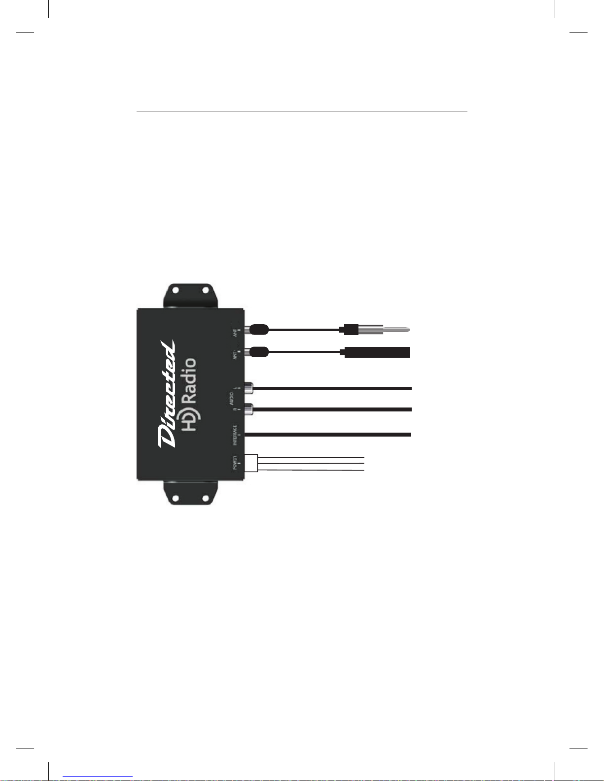
SETUP/INSTALLATION
Mounting the Commander module:
The unit comes with 2 brackets. There are two holes located on each
side of the unit that allow the 4 screws the unit comes with to hold the brackets
into place. The module is small enough to be mounted under a seat, in the trunk,
or possibly behind the dash depending on the vehicle. Avoid mounting near any
movable parts, places where there can be moisture, near high temperatures, or
areas that are susceptible to electric interference. Be sure the unit has proper ventilation. For example a rear seat in a car may not have enough space for proper air
circulation.
RED = +12 VOLTS SWITCHED
YELLOW = + 12 VOLTS CONSTANT
BLACK = GROUND
ANT OUT
ANT IN
INTERFACE
AUDIO
OUT
Power Harness:
Yellow - +12 volt constant. This wire should show 12 volts regardless of the posi-
tion the key is turned to in the ignition. It is located in the top right pin of the 4 pin
connector plug.
Note: If your sound system is set up with remote
amplifiers or line inputs the audio outputs can be connected directly to you system with RCA cables from
these Audio Output jacks.
Page 7

© 2006 Directed Electronics, all rights reserved
7
Red - +12 volts switched. This would be hooked to a wire that shows +12 volts
when the key is turned to the accessory or run positions but not show voltage when
the key is in the start position. This is the wire that tells the unit to turn on and off.
It is located in the lower right pin of the 4 pin connector plug.
Black - Ground. This should be connected to a chassis ground. This should be a
paint free surface. A good example is the kick panel. This wire is located in the top
left pin of the 4 pin connector.
Antenna In:
This is what allows the Car Connect to receive radio signals. The unit comes with an
antenna cable that has 1 male connector and 1 female connector on opposite ends
in order to extend the factory antenna wire. It may require the use of an antenna
adapter depending on what kind of vehicle it is being installed into.
Antenna Out:
This will allow the antenna to pass through to the radio's receiver. The unit comes
with an extension cable with 2 male connectors. One lead goes to the Car Connect,
the other goes to the antenna input for the car radio. This would still be required to
be installed even if using the RCA output, otherwise the head unit's tuner would not
be able to get reception anymore. This also allows for the fm modulator to output
signal through the selected radio station for radio's that do not have an auxiliary
input.
Audio output:
If the Car Connect is being installed in conjunction with a radio that has an auxiliary
input, the RCA output can be used. White is for the left signal and red is for the right
signal. This is not necessary to be installed if the desired output is through the fm
modulator only.
Interface:
The display connects on the 8 pin interface port located right on the main unit. The
display should be mounted in an area that makes it easily accessible. This could be
a center console area. The interface may be mounted with a double sided adhesive
such as Velcro or tape. Be sure the area is cleaned thoroughly first. Then apply the
adhesive.
Page 8

© 2006 Directed Electronics, all rights reserved
8
Installation Notes:
Initial Power-up defaults
1. Source defaults to FM
2. Frequency :
Preferred initial behavior : Tuner starts at 87.9 MHz
(Currently "Mhz" or "Khz" does not appear on the UI)
The bank number to store frequency is set to 1.
Loss of signal strength while playing HD
a. If stream does not resume within 10 sec,
Switches to analog signal (does not mute even if analog signal is
poor).
Flashes the "Blinking HD logo" screen overlay for 10 seconds.
Removes HD logo and updates display to analog signal type.
b. If stream resume within 10 sec,
Maintains previous SPS channel and display mode.
Discontinued supplementary channel while playing HD
If an HD supplementary channel is discontinued while the unit is tuned to it,
1. Mutes audio when stream is no longer available.
2. Shows "NOT AVAILABLE" screen overlay for 5 seconds. And jump to main
channel.
Page 9

© 2006 Directed Electronics, all rights reserved
9
COMMANDER CONTROLS
7
8
9
10
1
2 3
4
5
6
SEL
MENU
DISP
BAND
1
2
3
4
5
BANK SEEK
1. LCD
2. BAND BUTTON, The BAND Button selects AM or FM
3. DISPLAY BUTTON, Press the DISP button to cycle between the available display modes.
4. MENU BUTTON, MENU button will acces MENU options. It will also act as an EXIT
function when in a sub menu.
5. UP ARROW, Increases frequency selection
DOWN ARROW, Decreases frequency selection
RIGHT ARROW, Seek UP according to currently active Seek Mode
LEFT ARROW, Seek DOWN according to currently active Seek Mode
SEL, Used to select Menu options
6. POWER BUTTON, Pressing the Power Button will turn the unit ON or OFF
7. PRESET BUTTONS 1 - 5, Station presets
8. BANK BUTTON, The BANK button is used to select Preset Bank number for loading
and saving channel. Pressing and releasing this button changes the Preset Bank in a
circular list from A to D. When the bank changes, the radio tunes to the station last
accessed in the newly selected bank.
9. SEEK, Button selects between differnent modes
10. IR window
Page 10

© 2006 Directed Electronics, all rights reserved
10
REMOTE CONTROL
The button functions for the Remote Control are identical to the associated
buttons located on the Commonder. For a description of the button operactions
please refer to the COMMANDER CONTROLS section.
Page 11

© 2006 Directed Electronics, all rights reserved
11
CONNECTIONS AND BASIC OPERATION
Power On/Off:
Pressing and releasing this button turns the unit on and off. At initial "power on",
the display shall show the HD Radio logo as large as possible for 2 seconds. The
device will then display the default screen for the tuning mode that was used last
prior to power off.
Radio mode
The Car Connect has four operating modes as below. The following sections of this
document give detailed descriptions of each mode.
- Analog Radio Mode
- HD Radio Mode
- RDS Mode
- Setup Mode
Page 12

© 2006 Directed Electronics, all rights reserved
12
ANALOG RADIO MODE
If unit is turn on, the unit enters to Analog Radio Mode. In this mode, current tuned
frequency and band are displayed on the screen. And the preset indicator, Seek
indicator and Signal strength bars are displayed on Status line. If current channel is
previous saved frequency in Preset Bank, the preset number will be displayed with
Preset Bank. If HD signal is acquired, unit is converted the mode to HD Radio Mode
automatically.
Operation control in Analog Radio Mode
Button Operation
POWER Power off
BAND Band toggle (AM / FM)
EZHD User Interface Specification Rev 04
Ù
SEEK Select the Seek mode
EZHD User Interface Specification Rev 04
Ù
Ù
Ù
Ù
The Seek mode icon is removed after a short time-out
interval of about 5 seconds. And return to lasted display
screen.
Page 13

© 2006 Directed Electronics, all rights reserved
13
1-5 Direct tune to preset frequency on current Bank
Press and Hold : Store current station to current Bank
Press and Release : Recall
Repeat : Repeated press of the same button cycles
through secondary programs on multi-casting stations.
Ex) If press the button '3' in bank B mode,
EZHD User Interface Specification Rev 04
Ex) If press the button ‘3’ in bank B mode,
Æ
If saved channel is SPS channel, the unit is waiting for 10
seconds until the digital signal is acquired. And shows
'Linking' screen overlay for 10 seconds. If saved SPS
channel is not acquired within 10 seconds, the unit jumps to
main program immediately.
EZHD User Interface Specification Rev 04
Ex) If press the button ‘3’ in bank B mode,
Æ
If saved channel is SPS channel, the unit is waiting for 10 seconds until the digital
signal is acquired. And shows ‘Linking’ screen overlay for 10 seconds. If saved
SPS channel is not acquired within 10 seconds, the unit jumps to main program
immediately.
BANK Move the memory space for preset tune. The Bank box is
always displayed on screen. When the bank changes, the
radio tunes to the station last accessed in the newly
selected bank.
EZHD User Interface Specification Rev 04
Æ
Æ
This button changes the bank in ascending order through
all banks. Example A ' B ' C' D 'A (Wrap)
NAVIGATION
UP : Tune up
Page 14

© 2006 Directed Electronics, all rights reserved
14
DOWN : Tune down
RIGHT : Seek up according to currently active Seek mode.
LEFT : Seek down according to currently active Seek
mode.
SEL : No operation
MENU Enter to SETUP Mode
DMHD-1000 User Interface Specification Rev 05
Æ
Æ
DISPLAY Display Mode 1 Same as Display Mode2
Display Mode 2
EZHD User Interface Specification Rev 04
Ex) If press the button ‘3’ in bank B mode,
Æ
Display Mode 3 Same as Display Mode 2
Page 15
© 2006 Directed Electronics, all rights reserved
15
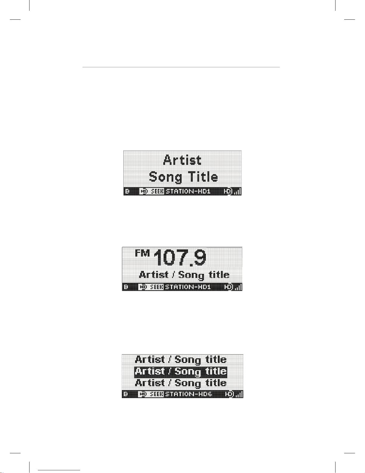
HD RADIO MODE
When HD signal was detected, current mode is changed from Analog Radio Mode
to HD Radio Mode and flashes the HD logo until the digital audio is acquired. The
several type of display will be shown according to the user selected.
HD Display Mode 1
In Display Mode 1, Artist and Title on separate lines are displayed. And the preset
indicator, Seek indicator, Short Station name, HD logo and Signal strength bars are
displayed on Status Line.
EZHD User Interface Specification Rev 04
HD Display Mode 2
In Display Mode 2, current tuned frequency and band are prominent in the center of
the screen. And artist and title on same line is displayed. The Status Line is same
the Display Mode 1.
EZHD User Interface Specification Rev 04
HD Display Mode 3
In Display Mode 3, when secondary audio is available, Multi-cast EPG is a list
of available audio streams on the currently-tuned frequency. The selected audio
program is highlighted and maximum 3 lines total displayed on the screen. The
Status Line is same the Display Mode 1.
EZHD User Interface Specification Rev 04
Page 16

© 2006 Directed Electronics, all rights reserved
16
Note: Electronic Program Guide (EPG) is a list of stations, services, programs and
detailed program information delivered by an HD Radio Station to support identifica-
tion, program selection and simplified tuning.
Operation control in HD Radio Mode
POWER Power off
BAND Band toggle (AM / FM)
EZHD User Interface Specification Rev 04
Ù
SEEK Same as Analog Radio mode
1-5 Same as Analog Radio mode
BANK Same as Analog Radio mode
NAVIGATION UP : Only main channel 'Tune up , with SPS channel '
Next program
DOWN : Only main channel 'Tune down, with SPS
channel ' Previous program
RIGHT : Seek up according to currently active Seek mode.
LEFT : Seek down according to currently active Seek
mode.
SEL : Select to desired Seek mode.
MENU Same as Analog Radio mode
DISPLAY Display Mode 1
EZHD User Interface Specification Rev 04
Page 17

© 2006 Directed Electronics, all rights reserved
17
Display Mode 2
EZHD User Interface Specification Rev 04
Display Mode 3 "Multi -Cast EPG" When secondary
audio is available.
DMHD-1000 User Interface Specification Rev 05
Page 18
© 2006 Directed Electronics, all rights reserved
18
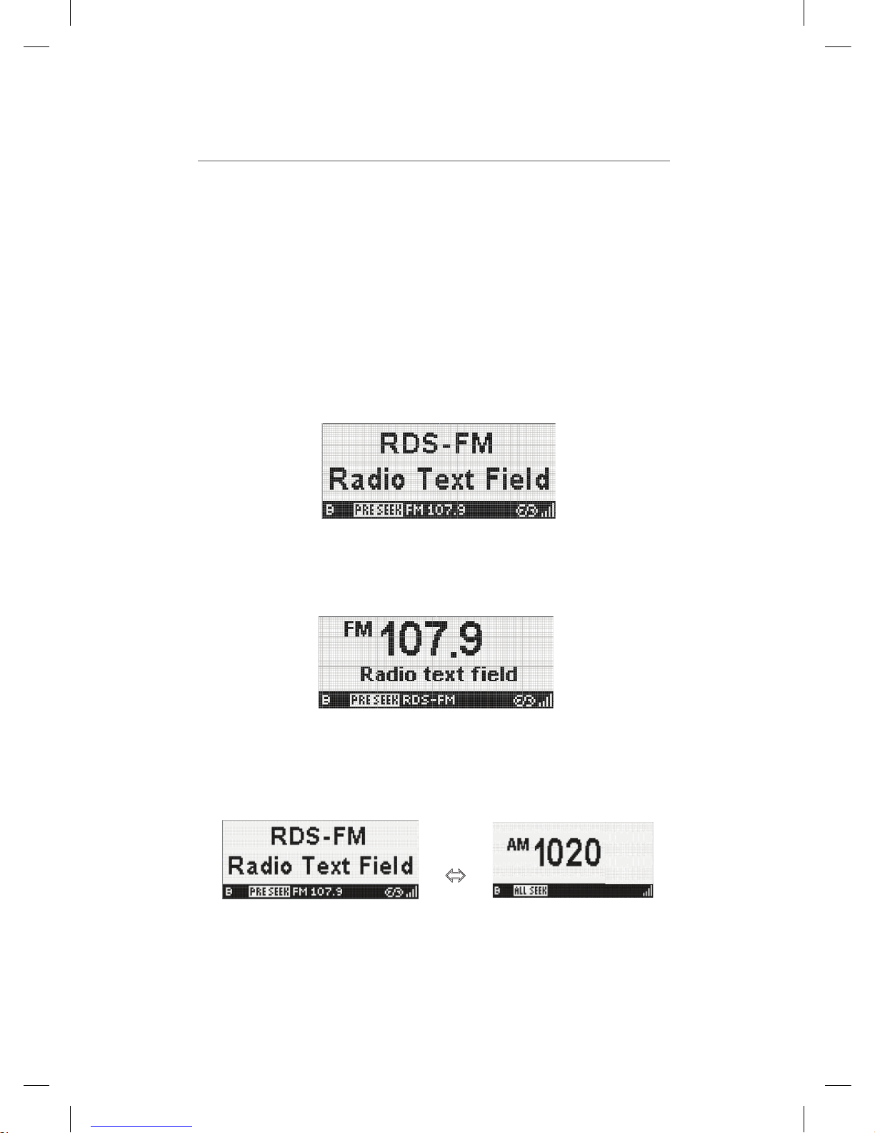
RADIO DATA SYSTEM (RDS) MODE
Note: RDS (Radio Data System): This technology allows stations to transmit additional
types of information via encoded digital signals that can be received and displayed by the
user's Radio. For instance: an RDS-capable Radio can display the title and artist or current
song playing, local traffic information, an advertiser's phone number while a commercial
is playing, etc.
When RDS data was received, the display is changed as below automatically. The display
in RDS Mode has two types of Display Mode.
In Display Mode 1, Station name and Radio text information on separate lines are
displayed. And the preset indicator, Seek indicator, band, frequency, RDS logo and Signal
strength bars are displayed on Status Line.
EZHD User Interface Specification Rev 04
In Display Mode 2, current tuned frequency and band are prominent in the center of the
screen. Artist and Title on same line is displayed. In this display mode, the station name
is displayed to Status Line instead of band and frequency.
EZHD User Interface Specification Rev 04
Operation control in RDS mode
POWER Power off
BAND Band toggle (AM / FM)
DMHD-1000 User Interface Specification Rev 05
Ù
EZHD User Interface Specification Rev 04
SEEK Same as Analog Radio mode
1-5 Same as Analog Radio mode
Page 19

© 2006 Directed Electronics, all rights reserved
19
BANK Same as Analog Radio mode
NAVIGATION UP : Same as Analog Radio mode
DOWN : Same as Analog Radio mode
RIGHT : Same as Analog Radio mode.
LEFT : Same as Analog Radio mode.
SEL : Same as Analog Radio mode
MENU Same as Analog Radio mode
Tune Up/Down Up : tune up
Down : tune down
DISPLAY Display Mode 1
EZHD User Interface Specification Rev 04
Display Mode 2
EZHD User Interface Specification Rev 04
Display Mode 3 No operation
Page 20

© 2006 Directed Electronics, all rights reserved
20
SETUP MODE
To enter Setup Mode, press the MENU button. Using the navigation keys, user can
select a desired item. To exit current menu tree, press the MENU button again or
wait for 5 seconds.
DMHD-1000 User Interface Specification Rev 05
Operation control in Menu mode
Version: This item is used to confirm current version.
LCD Control : There are two items to control the LCD screen.
RF Modulation
The On/Off Field is toggled by user selecting.
Page 21

© 2006 Directed Electronics, all rights reserved
21
SPECIFICATIONS
Voltage Range: 9V DC to 16V DC
Audio output level: . 0.5 V
Temperature Range: -20 to 60 deg. C
Fuse size: 2A
Current Draw on: .75A
Current Draw off: .005A
Item Dependancy Specification
Tuning Range FM Tuner 87.9MHz – 107.9MHz
Usable sensibility (mono) FM Tuner <= 2uV (SNR=35dB)
Quieting sensibility (mono) FM Tuner <= 3uV (SNR=50dB)
Image rejection FM Tuner >70dB
AM suppression FM Tuner, DBB >60dB
1st adjacent rejection FM Tuner, FE, DBB SNR=60dB at D/U= - 25dB
Alternate channel rejection
(+/-400kHz) FM Tuner, FE, DBB SNR=30-35dB at D/U=-70dB
Stereo separation (FM) DBB >60dB at 1kHz
THD (mono) FM DBB <0.3% at 1kHz
THD (stereo) FM DBB <0.3% at 1kHz
Output SNR (mono) FM DBB >70dB for pre-detection SNR>30dB
Full audio bandwidth DBB 20Hz-15Hz
Tuning Range AM Tuner 530kHz – 1710kHz
Spacing AM Tuner 10kHz
Usable sensitivity AM Tuner <= 25uV (SNR=20dB)
Tuner AGC dynamic range AM Tuner 55dB
THD AM Tuner, FE, DBB < 0.3% at 1kHz < 1% at 100Hz
Pre-detection bandwidth DBB Nominally 8kHz, Adjustable down to
3.5kHz
Post-detection audio bandwidth DBB Adjustable from 8kHz down to
3.5kHz
Signal-to-noise-ratio AM Tuner, DBB 50dB
DSP AGC DBB -12dB to +12dB
Items Specification Note
Input frequency range (AM) 530~1710 KHz
Input frequency range (FM) 87.9~107.9 MHz
IF Band width (AM) 10KHz(analog) ,40KHz(IBOC)
IF Band width (FM) 180KHz(analog) ,400KHz(IBOC)
Antenna input and output Impedance 75 Ohm Unbalanced
IF Output frequency 450KHz(AM), 10.7MHz(FM)
IF Output level (AM) 84mVrms
IF Output level (FM) 94dBuV
Page 22

N44000 12-06
 Loading...